


GAW
-
Posts
183 -
Joined
-
Last visited
Content Type
Profiles
Forums
Gallery
Events
Posts posted by GAW
-
-
March 2018
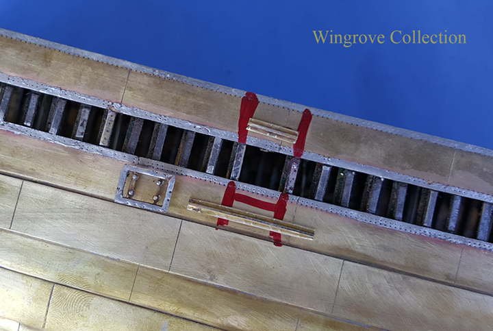
Fig-109 - With the Loading Port door in place on the strake of plating, we are now ready to put that in place on the hull. For this a Frame is cut, here we see it’s location and two lengths of angle iron (brass) Stringers to take the strain from the cut Frame.
It was not possible to get to this location on my last visit to the old girl, as the ladder down into what was converted into an oil tank, was all but rusted away and I thought better of chancing my luck on it. I have since seen photos of the area, from the recent survey, and there is nothing left of the original. The door has been welded up and a Frame length welded over it to make good the loss.
-
Thank you Xken, you are a lucky fellow, to have found a partner with understanding of creativity and can share it with you - never mind the noise, look after and bless her, they are gems.
If you enjoy my work and into ship modelling as I know you are with the excellent work on your current project, check out my ‘News & Comments’ page for March :
< http://www.wworkshop.net/Home_Page_/News%26_Comments.html >
An idea for a little sideline tool for you to make, that could make life easier on the more repetitive jobs, like the spokes for ships wheels and the ever present stanchions and elaborate turned posts on most subjects.
-
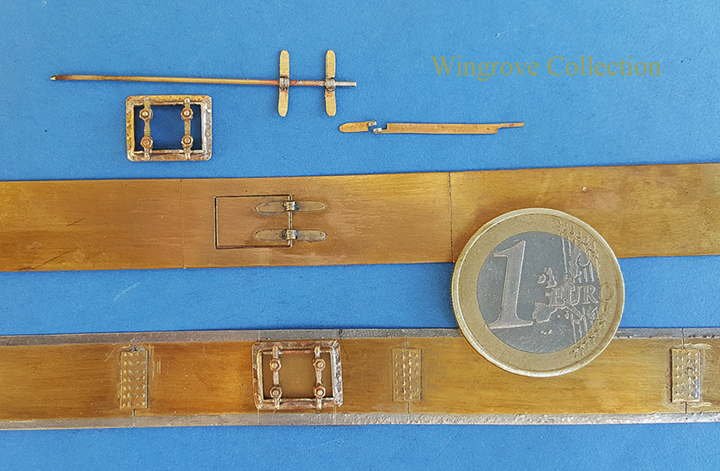
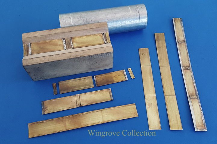
Fig-108 - A set of assembled parts at the top, in the centre is the strake of plating with door attached showing the out side, and at the bottom the second strake of plating for the other side of the hull, showing the complete door assembly attached to the inside, and including butt plates. The one Euro coin about the size of a quarter dollar will give an idea of there size at 96th scale.
-
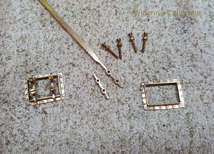
Fig-107 - Details of the construction of the loading port, all of which can only be seen on the inside of the hull. It consists of a square frame of the angle brass, provided with rivet heads. The two locking bars are filed up from rectangular brass, then drilled and tapped to take the four locking bolts. The bolts should be anchored to the inside of the door, but for ease of assembly and construction, and it cannot be seen anyway, the frame, locking bars and bolts were assembled with silver solder. Then tinned with soft solder for attaching to the inside of the shell plating. The slotted heads were of course removed. While the plate for the door with hinges were assembled with soft solder into a hole cut in the plating to take it while the hinges were soft soldered to the hull plating, as can be seen in the next shot.
- JOUFF, popeye the sailor, mtaylor and 3 others
-
 6
6
-
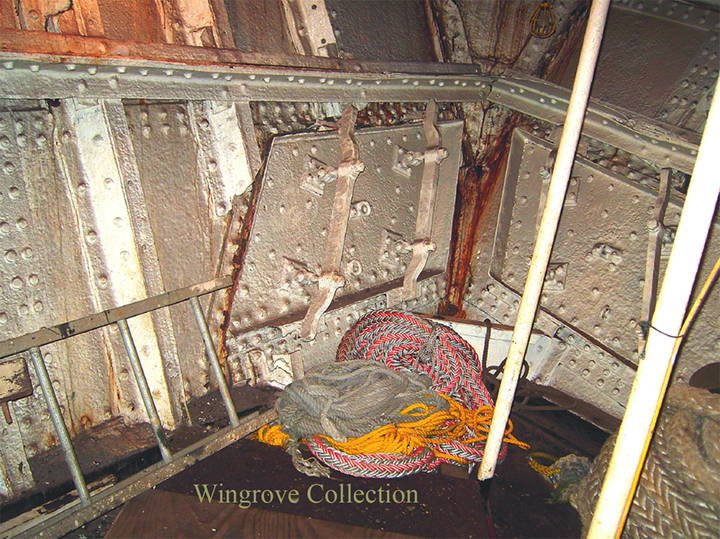
Fig-106 - This shows the two upper loading ports at the stem, leading onto the tween deck, and apart from the shape indicates what the inside of the side ports would have looked like, with the two large locking bars in place. Incidentally, the steel ship Balclutha in San Francisco also has timber loading ports in the sides, and are complete with these same style of locking bars in place.
-
February 2018
Fig-105 - The Falls of Clyde was built as a general cargo vessel, but with special ports in the sides and at the bow for loading timber. There are four in the bow, plus two others, one on each side, at the midship section onto the tween decks. It is interesting to note that on the original draft of the cross section of the hull, dated 1878, no planking is shown on the tween deck, but is shown on the main deck and in the hold. Diagonals and stinger plates, are shown, which makes one wonder, if the planking for the tween deck was temporary and considered as part of the cargo. Here we see the impression in the Falls of Clyde hull plating of one of the side loading ports. The port appears to have been welded closed when she was converted to a tanker, but the position of the hinges is still plain to see.
It was not possible to access the side tanks at the time of my last visit to photograph the inside of the side loading port, it was hard enough to get permission to get on the ship at all because of the sorry state it had been let to get into by the Bishop Museum, and only then after signing a declaration that it was at my own risk. However I have since seen photos of the inside at this point, and it is just a welded plate in place of the original door.

- druxey, JOUFF, popeye the sailor and 1 other
-
4
-
Fig-104 - One strip of ‘Out Plating’ needed to complete the sides but it calls for some fittings to be attached first, these being loading ports for Timber.

-
Fig-103 - Showing the inside of an ‘Out’ strip of Ships Plating. Note the Butt Straps and the slight curve of the Sheer, but no rivet heads. Each of the Frames has been provided with a Filler Strip to accomodate the Out Plating, so this strip is now ready for soldering in place.

-
-
Fig-101 -After all of the ‘In’ Plates are attached, and the Filler Strips soldered between at each Frame the Out Plate is ready to be attached. This is done by first fluxing the joint and then locating it precisely with the ever useful Sellowtape. After which a flattened tip of the Carbon Rod resistance soldering unit is used to lightly spot joint the strip in several places. when all is satisfactory the flattened tip can be slowly and carefully run along the edge of the strip to make the joints. This needs to be done with great care, by first securing the model and your self in a comfortable position, then placing the Carbon rod in position, before switching it on. Then with a follower - to hold down what has been heated and soldered, held behind the Carbon Tip it can be moved along the edge to melt and solder the running joint. Then switch off before removing the hot tip, or spark erosion may occur, that with only a very thin brass being soldered, will likely mean a hole burnt though it.
- druxey, mtaylor, douglaspbrown and 7 others
-
10
-
January 2018
Thank you all for your generous comments - necessity is the mother of invention, so they say - wanting to eat, when you have just given up a paying job to take on the world single handedly really does concentrate the mind, when it come to designing and making jigs and tools to help the process along. A happy, healthy and productive New Year to you all.
- douglaspbrown, John Allen, mtaylor and 3 others
-
6
-
I have only just found this Log Michael, You are a lucky man, you have a pandoras box of lost arts, and the making of a very good book - ‘The Lost Arts of Bassett Lowke’ - these models were made at a profit so will be full of efficient and repeatable techniques with out the use of CNC and 3D printing.
I have not had chance to check out your full Log YET, but If you are still looking for wire rope. Check out: <http://www.tecni-cable.co.uk> for the real stuff down to the finest - I have wires from them down to .002” - and sold by the yard. Note that the multiple strands 7X7 & 7X19 can be separated and run through a flame to darken and straighten them. I note that some one mentioned early on about making wire rope on a Rope-Walk. This cannot - successfully - be done, as the numbers do not add up - 3 & 4 (strands) for hemp, but 7 (strands) for wire. What a fantastic job. Gerald
-
Fig-100 - Showing the inside of another strip of plating, ready curved and provided with the required Butt Straps at each join of plates. This being an ‘In’ plate, it shows the double row of rivet heads to the upper and lower edges. It being the other side that is tinned to accomodate the ‘Out ‘ plating.
- oneslim, popeye the sailor, JOUFF and 9 others
-
12
-
Fig-99 - With the Plating taken around the Bilge, I next made and attached the Upper Deck Sheerstrake, this being on the Falls of Clyde the uppermost ‘In’ plating and just above the level with the Main Deck. The very slight curve of the length was created as described at Fig-94, by tapping lightly along the lower edge with the flat of a repouse hammer. This needless to say before the rivet heads are applied.
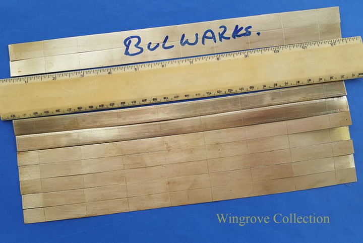
Part of the upper works is a wide Stringer plate that runs around the Hull at deck level to the out side edge of the Frames and riveted to the deck beams. On top of this on the out side edge, runs a length of angle iron, there is also a second one inside of this and parallel with it, riveted to the Stringer plate, between which forms a Gutter, or the Scuppers. It is to the out side angle iron that the Upper Deck Sheerstrake is attached at the top. The plating is provided with two rows of rivet heads at the top and bottom, it is the lower of the top two rows that line up with this angle iron. The upper row, together with the lower one are both used to rivet the Bulwarks in place.
The strip of plating is clamped to this top length of angle brass and on the lower edge to the Frames and where good contact is made with most of the Frames, touched with the Carbon Rod tip to make the joint. It is not necessary to attached every Frame, as all are firmly held in place by being attached to the Stringers on the inside. However the side deck Stringers with the angled brass length attached on top, make for a smooth run for the Upper Deck Sheerstrake to be soldered to it for all of it’s length.
- John Allen, hexnut, albert and 9 others
-
12
-
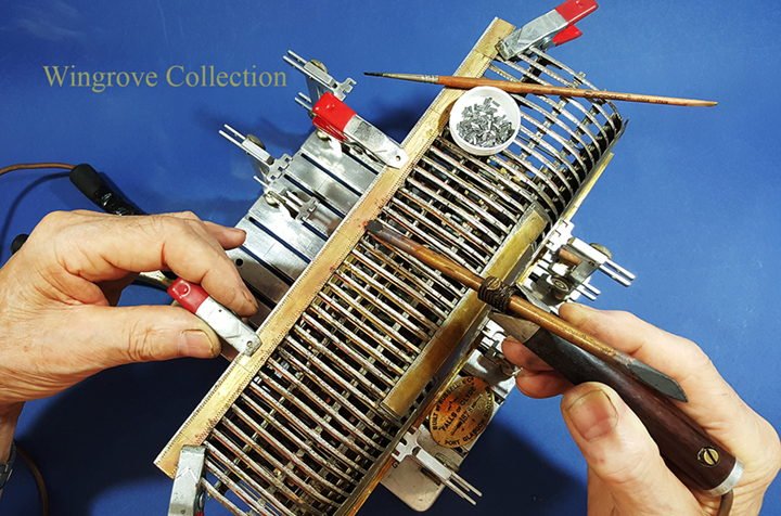
Fig-98 - Before the plating is finally fitted (soft soldered) in place, a small length of angle iron (brass) first has to be attached to every junction where a Stringer crosses a Frame. In full size practice this would have been riveted to the Frame before the Stringer was riveted to both, (Fig-78-A) but on this scale, it is better able to be done at this stage. The small lengths of brass angle ready tinned can be seen in the dish, all chopped exactly to length with the aid of the miniature Guillotine (Fig-40). Each is provided with a tiny spot of flux, placed in position then touched with the carbon tip to melt the solder and make the joint.
Note that I do not say, “touched with a HOT carbon tip” In resistance soldering one always ‘touches’ the part with a COLD carbon tip, then press the foot switch on, when sufficiently heated to melt the solder, the foot switch switches it off, and it can be removed from the work. To touch the part with a live - hot - carbon tip, is to destroy it via spark erosion. A couple of mistakes soon teaches the right way to do this.
The order of plating is to fit the ‘In’ plates first, then between these short lengths - Fillers Strips (Fig-78-C) - of brass strip of the same width as the Frame, and thickness as the Plating is soft soldered to each Frame, between the two rows of ‘In’ Plates.
- druxey, wefalck, popeye the sailor and 6 others
-
9
-
Fig-97 - I started off the plating by making and fitting them single, then found it less of a problem to make the plates in strips, with just a scored line to mark the joins. However in both cases the Butt Straps are required on the inside, to join each of the plates together. these are provided with four rows of rivet heads and made in long strips and cut to length as required. All parts are tinned with soft solder on the contact sides, so that the minimum of heat applied to the parts with the aid of the carbon rod soldering unit is all that is required to make the joint. Where the Bilge plating rounds the Frames the plates are curved with the simple die and punch, in this case a carved hard wood block, and a short length of 1.250” aluminium bar. The brass plating is only .010” thick, so it is very simple to manipulate, once the initial curve has been imparted to it.
-
I did not realise until about two thirds through the month. that last month was a very big life changing anniversary for me, that you might well find of interest - also some new photos of FofC No.3 - for more details check out:
< http://www.wworkshop.net/Home_Page_/News%26_Comments.html >
- tlevine, druxey, popeye the sailor and 1 other
-
4
-
December 2017
Thank you Johann for your generous comments, I am honoured to have your visit, having checked out your own excellent work in the field and envy your ability to manipulate tools. I never could get one of those jewellers saws to cut a straight line, much less follow a pencil line as close as your very good self. And you work so cleanly, I can only assume that you are a brain surgeon by profession.
- popeye the sailor, druxey and mtaylor
-
3
-
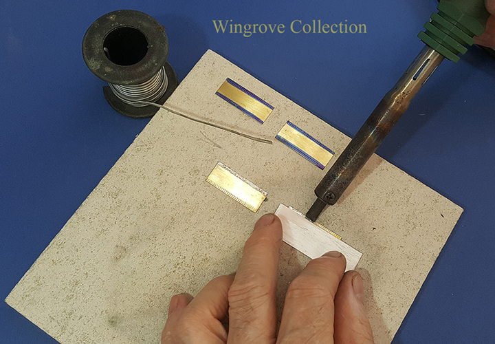
Fig-96 - Now with the rivet head side of the Plate down, and a small sheet of aluminium held on the back of the Plate, and just clear of the depressions of the rivet heads, apply a very small amount of flux, then drag the loaded soldering iron along the edge of the exposed Plate edg. the aim is to leave just sufficient soft solder - tinning - in place to make the soldered joint in the final assembly, with out additional squeezing out from under the Plate of excessive solder..
-
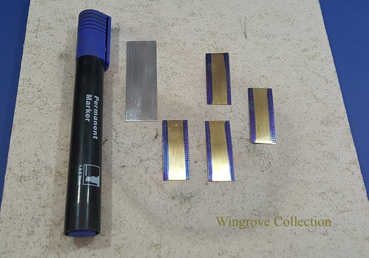
Fig-95 - For individual Plates, as well as strips, after they have been run through the RHM, to produce a double row of rivet heads on the long sides. the Plates will then need to be tinned with soft solder for the final attachments. Soft solder will not stick to a dirty surface, and above all we do not want solder around the tiny rivet heads, as it is all but impossible to remove. To overcome this, apply the tip of a felt tip marker pen to the area where the solder is not wanted.
-
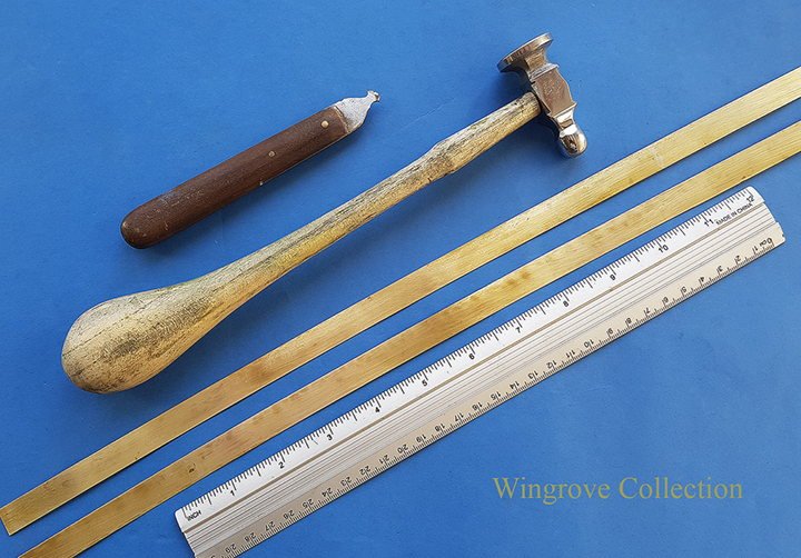
Fig-94 - The sheet cutting tool - top - made from high speed steel flat, ground at the cutting end, into a sharp ‘V’ form, then undercut to form a hook, so that when scribed across a sheet of brass, will form a simple groove. From past experience this is very easy to turn to accomodate the very slight sheer at the centre of the hull, by tapping very lightly along one edge from the centre outwards left and right, with the flat pain of a hammer - preferably a repouse hammer. If it is too much, then tap the other edge, and it will go back.
Working sheet metal had always been a mystery to me, until I read a book on Silversmithing, where the Smith can take a flat disk and with just hammering, can form it into a beaker. The biggest revelation to me was to learn that, one can ’thicken’ the edge of sheet metal as well as make it thinner, just by hitting it with a hammer. To see this in action, check out the link:
< http://www.wworkshop.net/2.3_Alfa_Build/Gallery-18.html >
-
November 2017
Fig-93 - With the Framing complete we now come to the Plating. As I stated right at the start, I had to imagine the construction from start to finish, to be able to create the tooling required before I could even start the project, for as far as I could assertion, no one had written on the subject regarding building an iron ship in miniature, to show the actual construction. As I hope we have seen so far, my assumption as to how to proceed has produced something resembling the aim of the project.
With the ships Plating - which is somewhat far down the line in the construction process - although some Plating has been attached to get this far, but only to assist in holding the Frames in position, until the Stringers were in place, my original thoughts have changed slightly when I actually got to this point.
Not being one to take two days on a process, when I can find a way of doing in in two hours, a close look at the actual Plating methods on the full size ship, looked somewhat daunting. However I did start to proceed down that road, each plate cut to size and rivet heads applied. Tye Plates attached, curved to form - the sheer line - then attached to the Frames. Once in place I had second thoughts, the finish was not quite what I had intended. I decided that I do not need individual plates, I can better do this in strips with the plates scribed in the appropriate places, particularly for the ‘Out’ Plating, as no rivet heads show, they being countersunk, and on this scale invisible. Also I was a little concerned with the out side finished look of the Plating, it was not as smooth and even as I had wished for.
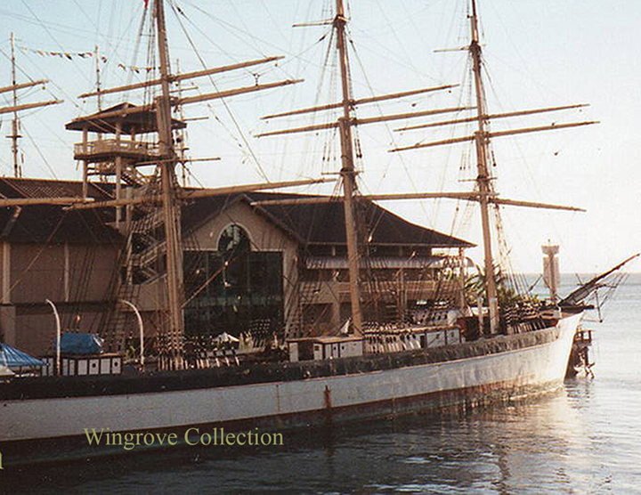
For the past 35 years I have been creating miniatures of classic cars, the finish of which is high gloss and perfectly flawless, so my mind-set was somewhat amiss with regard to the new subject. Then going through my hundreds of photos of the Fall of Clyde, I came across this one taken against a setting sun. OK she is 139 years old, and we all get wrinkles as we grow old, But this is iron plating attached with rivets and the use of hammers, in a very big way. This is not a modern yacht with polished fibre glass hull. With that in mind I was a little happier, a not ‘high gloss’ paint finish, and a ‘very’ slight irregular finish is part of the character of this subject, even when new.
My problem with the Plating had been trying to attach each individual Plate to each individual Frame, and getting more wrinkles than I needed. Although ideal, it is not necessary for the finished project. The Plating to be looking to scale, has to be no more than ‘010” thickness, as the actual full size Plating was only 11/16” thick when new, this is still slightly oversize, but for me acceptable. It is next to impossible (for me) to make every Frame + or - .001” correct to it’s shape and position for it’s full length in the miniature, and soft soldering a 010” thick brass Plate to several of the Frames, is not sufficient to pull the the Frames into line - as I think to some extents would be the case in full size practice, as the thickness of the wrought iron of the Frames is somewhat thinner than that of the large iron plate to which it is hammered home in the riveting.
With lengths of plates marked out on a single cut strip seemed the order of the day. These were cut with a simple ‘V’ shaped tool, working from both sides, so when almost cut through, a slight bending will break off the strip.
-
Thank you for your comments, always pleased to have them. Regarding Resistance Soldering Druxey, yes it can be used for silver soldering, if you have the power, however it is more akin to spot welding, as if you move the carbon rod at those temperatures, you are very likely to get sparking - ie, spark erosion - and in place of a joint you will likely have a hole. Better to stick with a flame for silver soldering. However if it is a ‘must have’, flux the parts, place a sliver of silver solder between the parts, hold them all together with the tip of the carbon rod, then switch on and hold you breath - it can be made to work.
For those of you interested in looking into the future - as I stated right at the start, this is number two of a trio of models of the Falls of Clyde, number one being the half model, that was used to furnish the shape of the Frames used here.
Number three is now well on it’s way. being the fully rigged, sails furled, water line model, that will also be featured in this Build Log, when it is completed. For a quick - one month only - look see, check out the following link:
< http://www.wworkshop.net/Home_Page_/News%26_Comments.html >.
I now have the full length - width - and the hight of the subject, it is just the filling in-between that is going to take up the time. The masts and three lower yards on each, are clothed in .010” brass sheet, as per the originals were made with wrought iron plate, however I have left inside the original hard wood sticks, for added strength and convenience.
Brass and nickel silver wire are used though out, with silver soldering used to create the parts, and soft solder to assemble them. Why Nickel Silver wire?? - I happen to have a lot of it, and find it much stronger and harder than brass of the same size. Small eyes formed in Nickel Silver wire are more likely to take the strain than brass or copper, which would likely open up, so would need for eachto be silver soldered closed to avoid this,
-
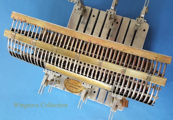
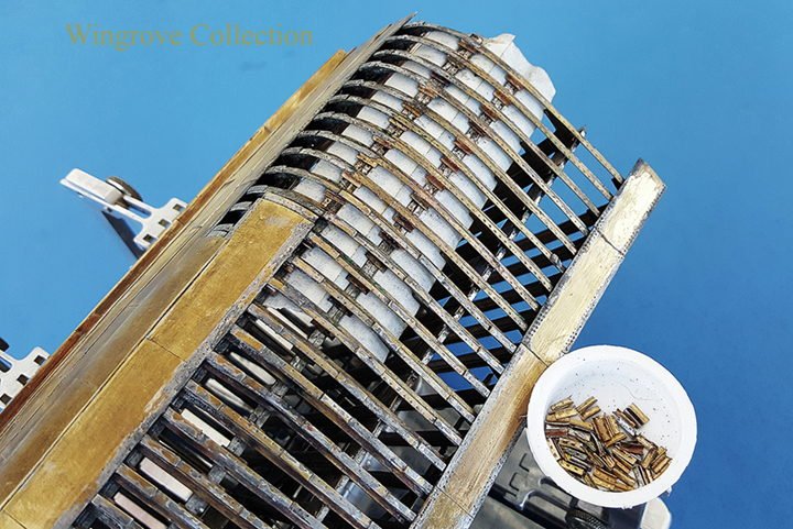
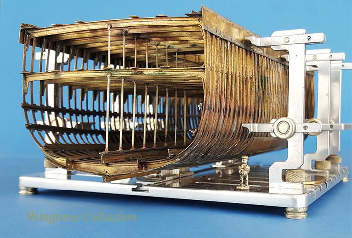
Fig-92 -The forty centre Frames are now in place will all attachments - note Jock the riveter standing by - always useful to keep an eye on the scale of all things. The next stage is the plating of the hull.
Falls of Clyde 1878 by GAW - FINISHED - scale 1:96 - iron 40-frame hull center cross-section
in - Build logs for subjects built 1851 - 1900
Posted
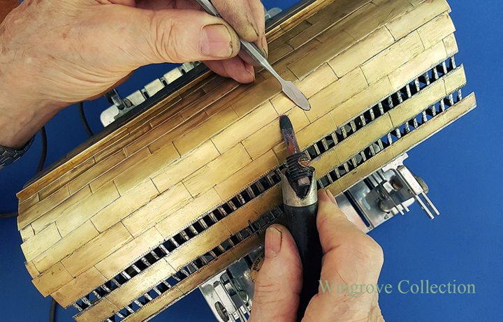
Fig-110 - An aluminium plate is bent up to form a guide through the hole to support the stringers on the inside, while they are being soft soldered - with difficulty - inside. As we have seen before, this is where the carbon rod resistance soldering unit comes into it’s own. It would be all but impossible to get a regular soldering iron in here.