


gak1965
-
Posts
611 -
Joined
-
Last visited
Content Type
Profiles
Forums
Gallery
Events
Posts posted by gak1965
-
-
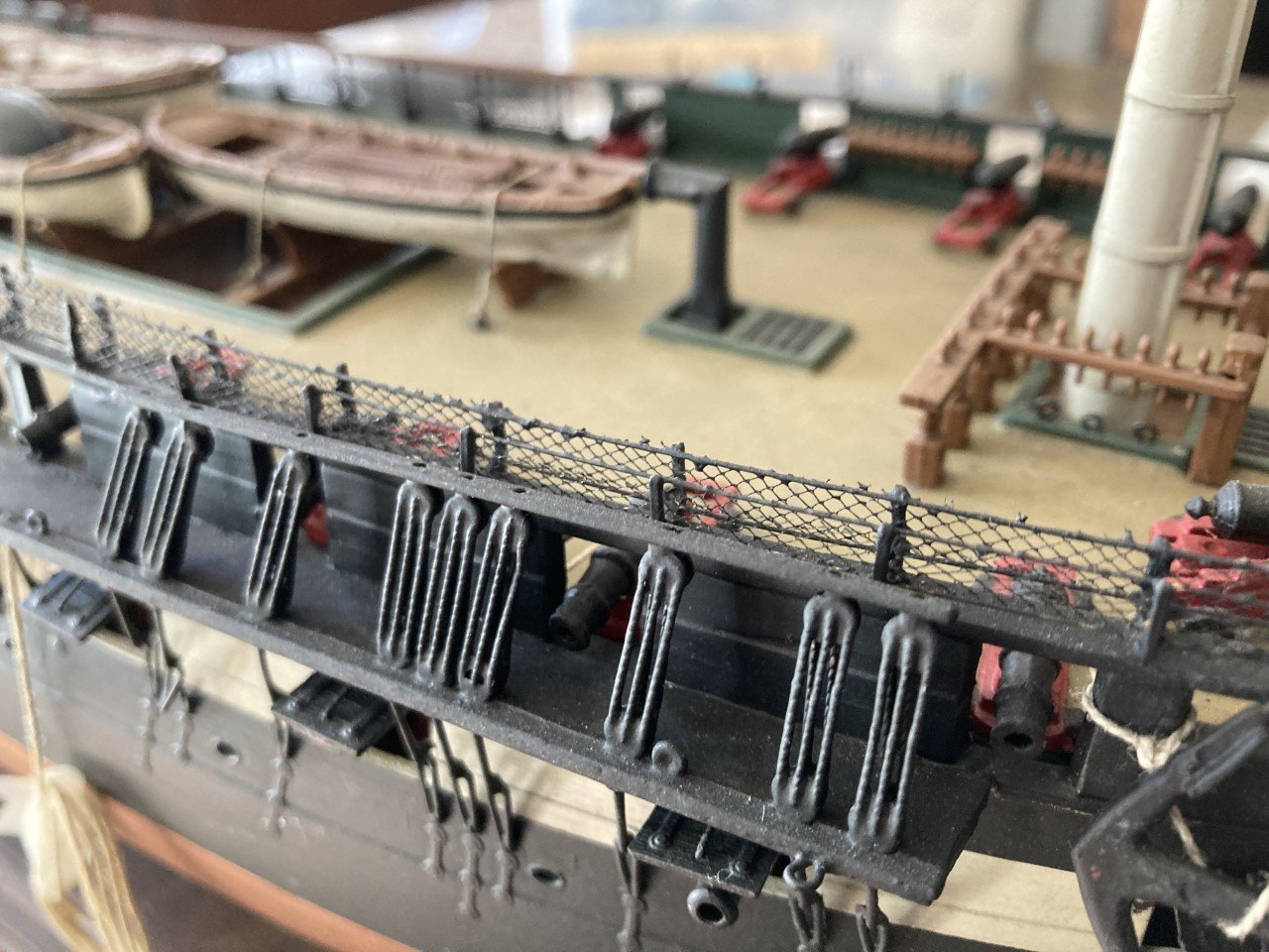
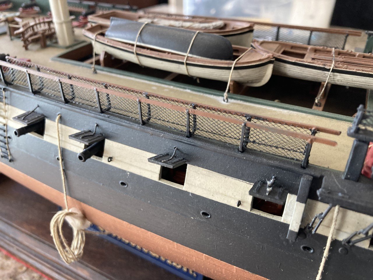
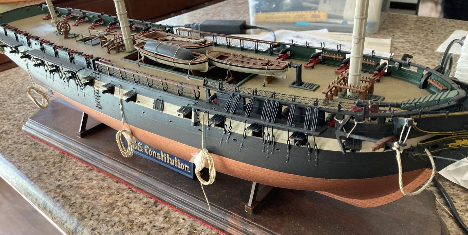
On 5/8/2022 at 12:39 PM, bcochran said:
What is the large rope along the lower area of the bulwark for? It is hanging by ropes tied to the rail, I think. It might be some kind of protection against things crashing into the stanchions and such during rough seas. I read in Lubbuck's book of several times when the deck as completely underwater and all that could be seen from above were the masts sticking out of the foam. Items not tied down must have crashed into the firm stationary parts of the deck.
That photo doesn't look like it was taken while they had any kind of sails set. I see that it is lightly attached to the rails, but you might just as easily suggest it is a mooring line (I think I see it going into a chock in the upper part of the photo) being kept off the deck, perhaps to prevent it from sitting in water and rotting?
-
On 5/1/2022 at 7:29 PM, bcochran said:
Here are a few pics of the Revell USS Constitution I was working on before I started breaking parts off. I could not get the deck to look the way I wanted. I detailed the gun deck, even though you can't see it. I am anxious to do another one if and when my Cutty Sark is finished. I keep the busted Constitution on hand for inspiration.
In my stash of large ship models, uncompleted are the Heller Victory, Santa Maria, the Revell Yacht America, Kearsarge, Constitution and Lindberg Sea Witch.
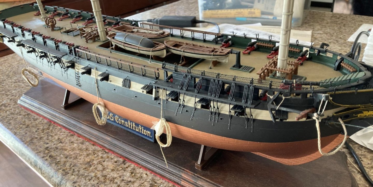
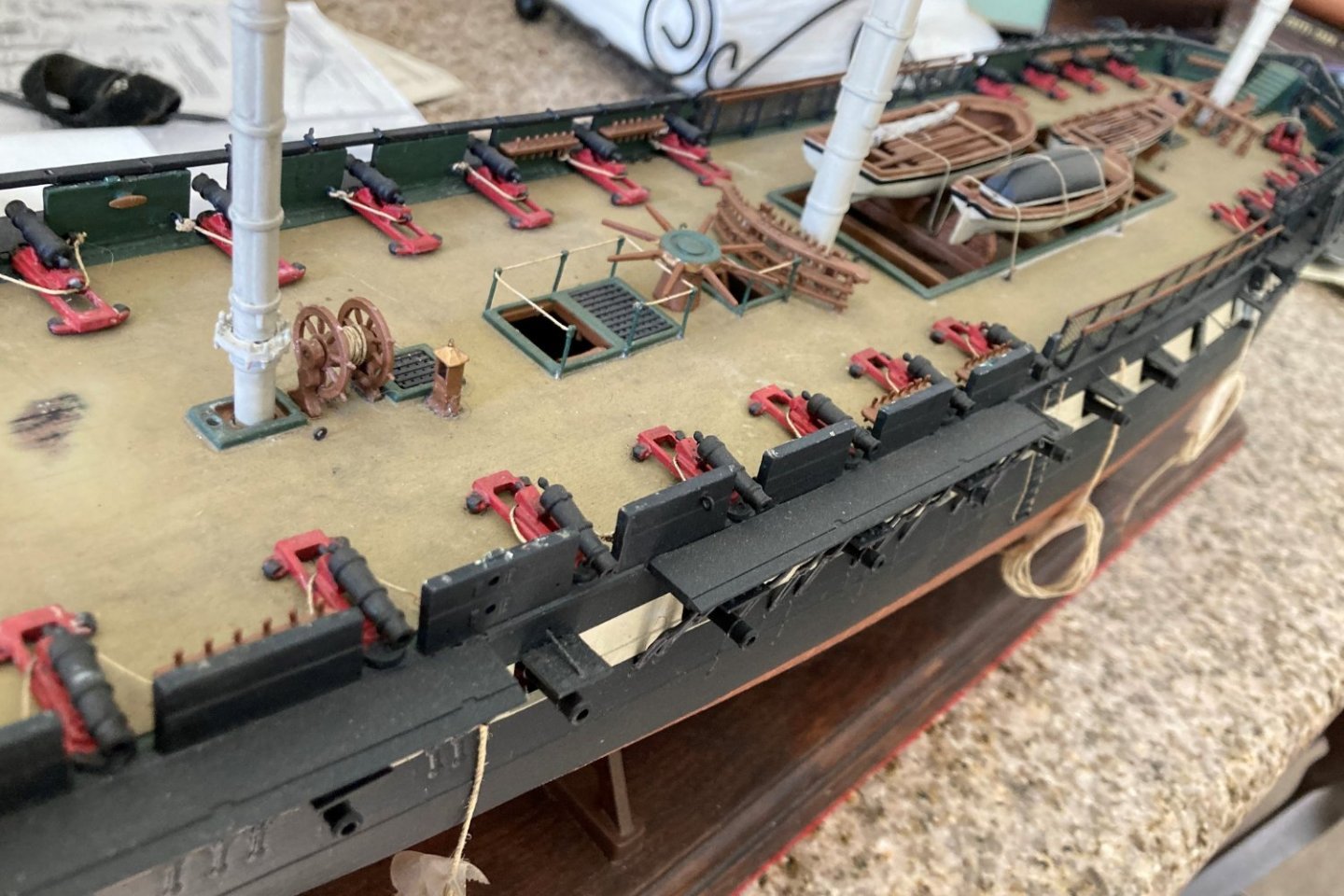
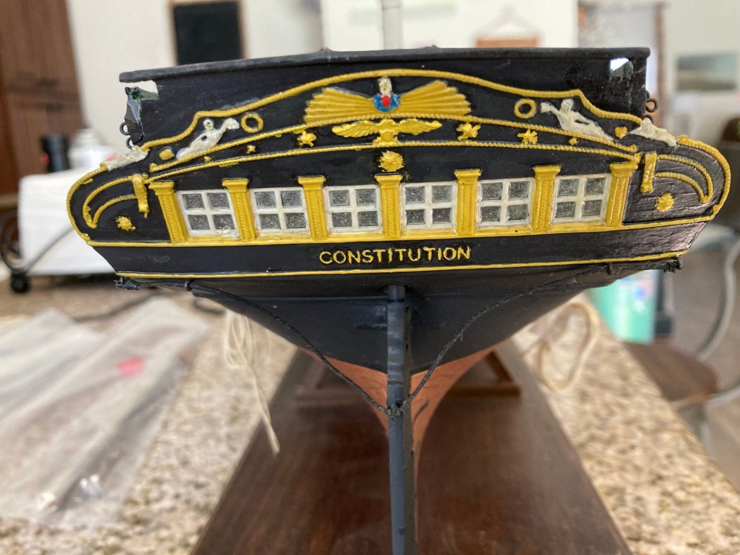
That's a great looking Connie! No reason to stop, everyone breaks things and had to repair. Once the basic hull is done, assume you are going to break something at least once every three sessions until the standing rigging is in place (it helps stabilize all those spars in the model as in life), at which point it'll drip to maybe 1 in 4 or 5 sessions. That's why we put them in cases (well and the dust).
I more or less mashed all of the rigging on the bowsprit and broke off the jibboom of my Niagara at one point (a story or almost mind boggling stupidity on my part). It was fixed and moved on.
Both ships are looking great!
George K
-
2 hours ago, ClipperFan said:
We discovered that the masts of Glory of the Seas were 4' shorter than they should have been.
This intrigues me. Do you mean the estimate of how much the spar projected from the deck was 4 feet shorter than you thought (caused by thinking that a spar of length n was stepped further vertically in the hull)? Or something else?
-
1 hour ago, ClipperFan said:
Flying Fish construction details from Duncan MacLean's incredibly detailed description of her at launch. Included is a description of the exact diameter range of standing rigging on the ship herself. He also mentions that iron was used for the shrouds. Anyone wanting precise construction details of many of McKay's Clippers can find them in Lars Bruzelius's website.
Yes, Lars' site is a great resource. The numbers from there and the plans definitely match up, although you need to know (as I do now) the the dimension being listed for the ropes are circumference not diameter.
I assume you mean iron for the futtock shrouds? That is consistent with the plans and I approve since it's way easier to make them out of wire 🙂 than string.
Regards,
George K
-
2 hours ago, Rick310 said:
George, I’m not sure but I think the sizes given are the circumference and not the diameter. I need to check the plans when I get home. I think on plan 4? There is a conversion table
Rick
That makes sense. 10.5 inches in circumference is a 3.4 inch diameter which is 0.035 inch at scale, against a .028 largest diameter thread provided with the kit.
I knew something was off in my read of the plans.
Thanks!
George K
-
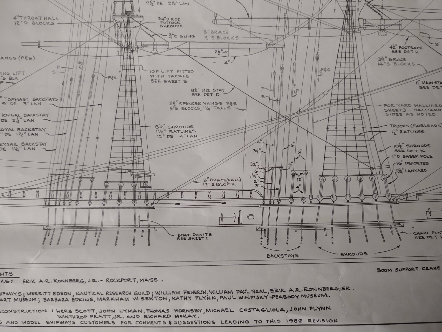
Hi all. I was hoping to reach out to the collective wisdom of the FIsh and McKay clipper ship builders out there. Having finished fabrication of the starboard side chain plates for the fore mast has me thinking that I will soon be able to start running shrouds, and I find I often need to spend a few days staring at plans to understand everything that needs doing properly. Usually the shrouds are pretty straightforward, but this time the plans do not make much sense to me, so hence my questions to you all.
Take a look at the segment of the plans below showing the lower shrouds for the main and mizzen masts:
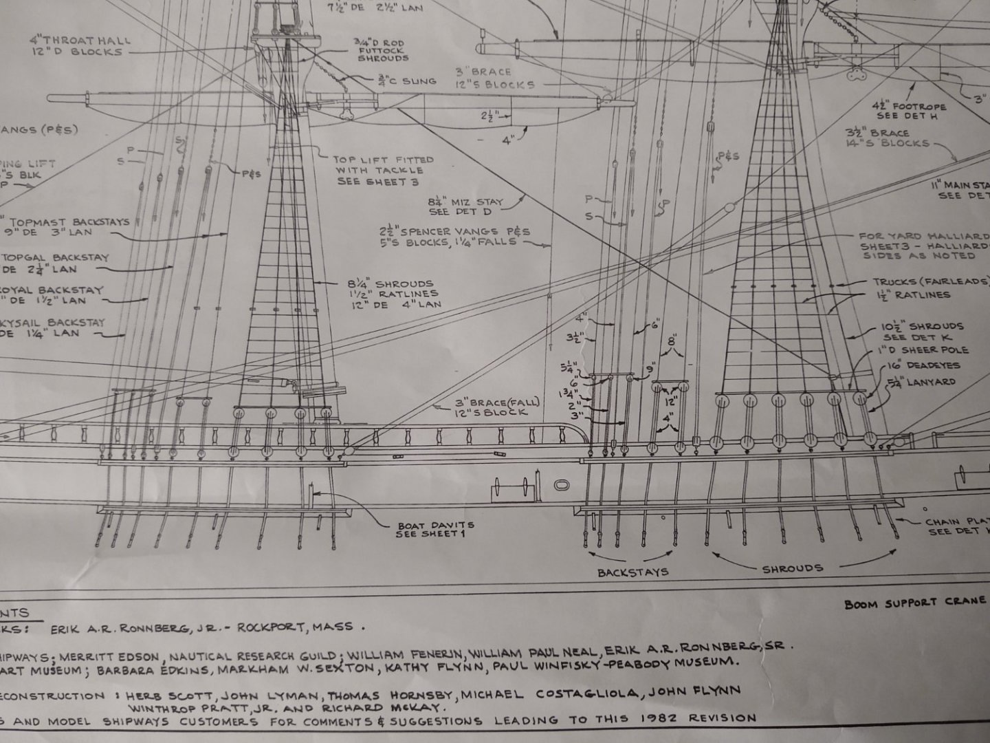
Most of it makes sense. For example, looking at the main, we have 5 different size deadeyes (16", 12", 9", 6", and 5.25") that are reduced to the three supplied deadeye sizes supplied with the kit (3/16 for the 16", 1/8" for the 12, and 3/32 for the rest). Fine. But the rest of the numbers make no sense to me at all. 10.5" shrouds on the main with 1.5" ratlines (right side of the image just over the shroud lanyards)? 8.25" shrouds with 1.5" ratlines on the mizzen (right side of the shrouds, halfway up)? That can't be right, those are the sizes of mooring lines on aircraft carriers, not shrouds on a clipper. The lines arranged side to side would cover more than 1/2" on the model at the top. And at scale a 10.5" line would be 4 times the diameter of the largest line that comes with the kit.
I must be missing something here. Open to any suggestions as to where I have gone astray, or thoughts around 'typical' shroud sizes on McKay clippers.
Thanks in advance,
George K
-
On 4/19/2022 at 10:35 PM, rwiederrich said:
They turned out swell.
+1
-
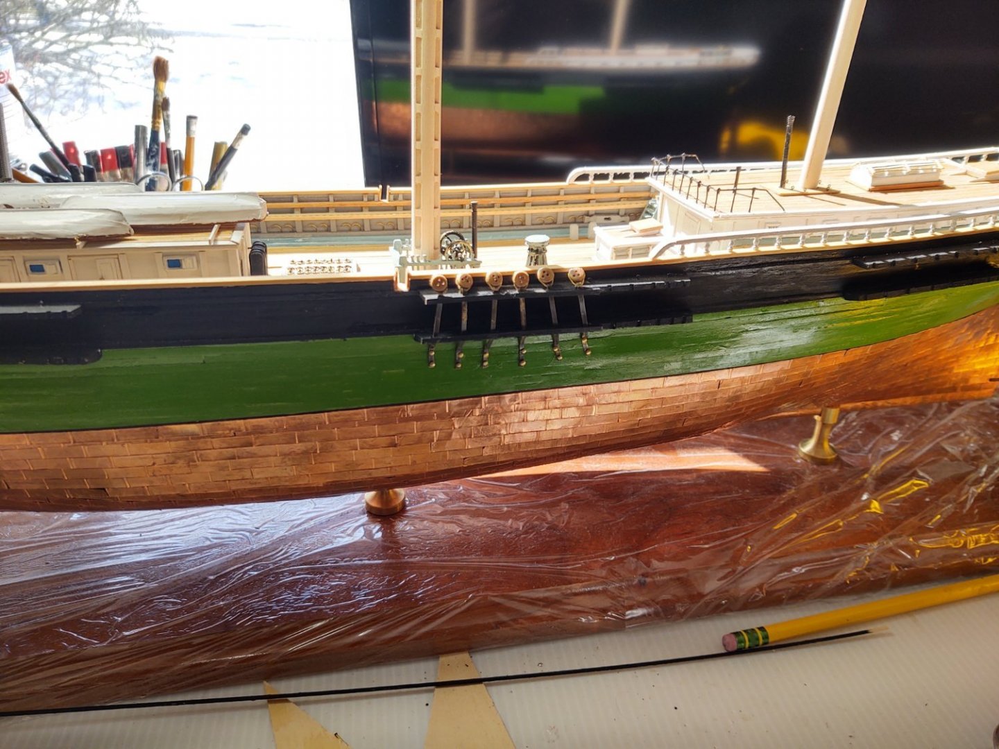
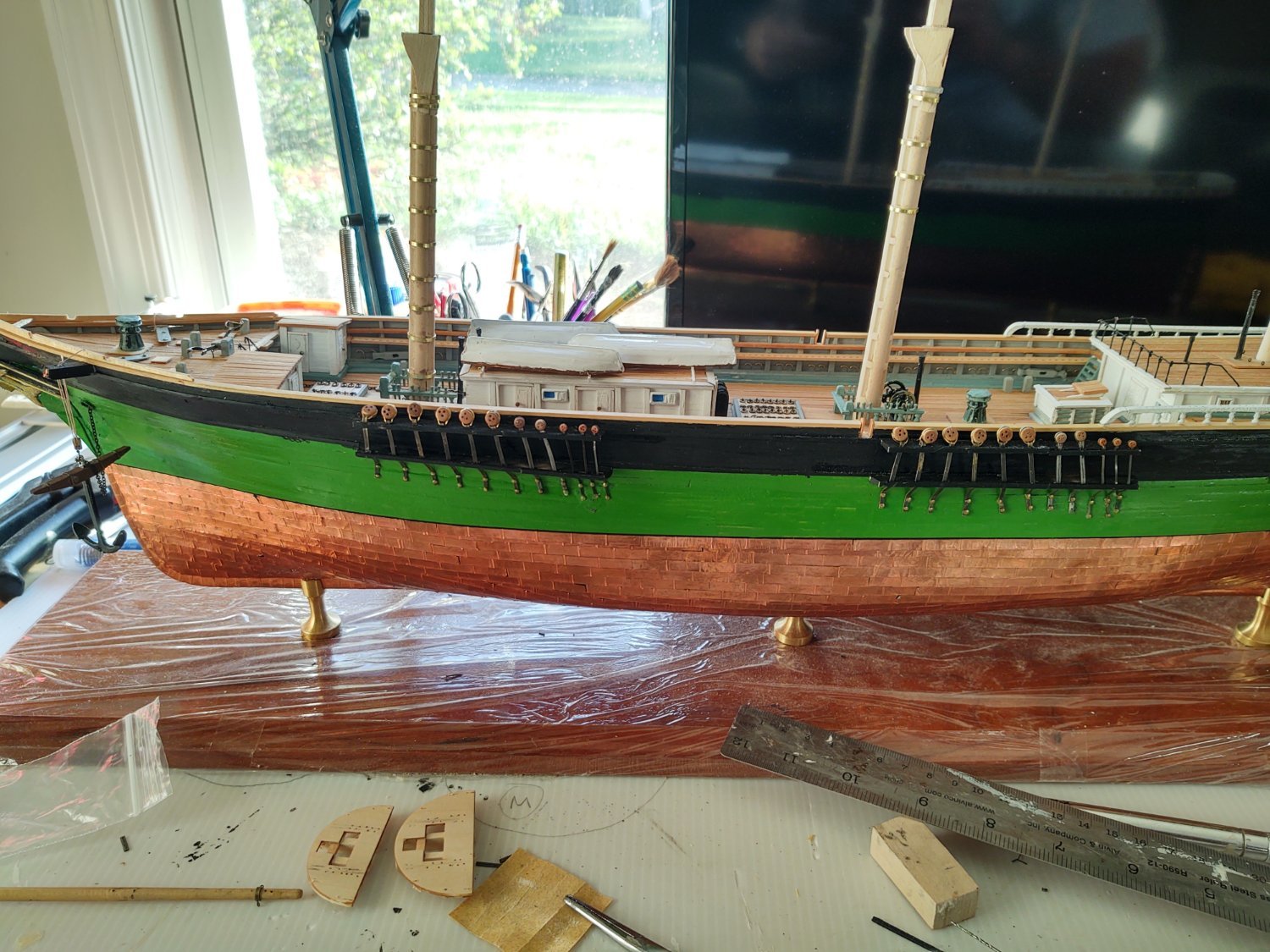
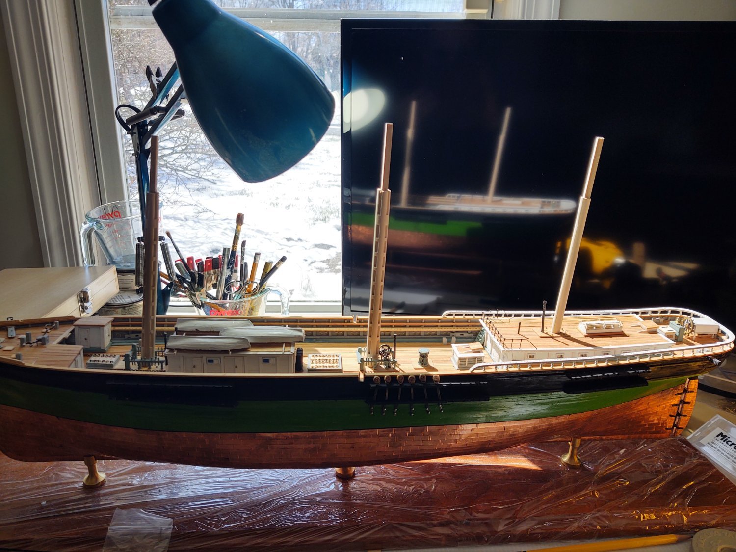
A short update on the progress of the Fish. For some reason, the chain plates and deadeyes were turning into a bit of a blocker for me. However, I received the material for making the plates for the lower backstays from BlueJacket and so no excuse. I have finished channels and plates on the port (or as I called it earlier the non-display or "practice") side of the ship - 16 for the shrouds, 6 for lower backstays and 9 for the upper backstays. The starboard side should now follow pretty shortly. The photos below show them reasonably well. I started with the main, moved to the mizzen and then finished with the fore, and you can see that the practice helped. The mounts on the hull are a lot straighter by the time I got to the fore, so hopefully that will continue on the 'display side.

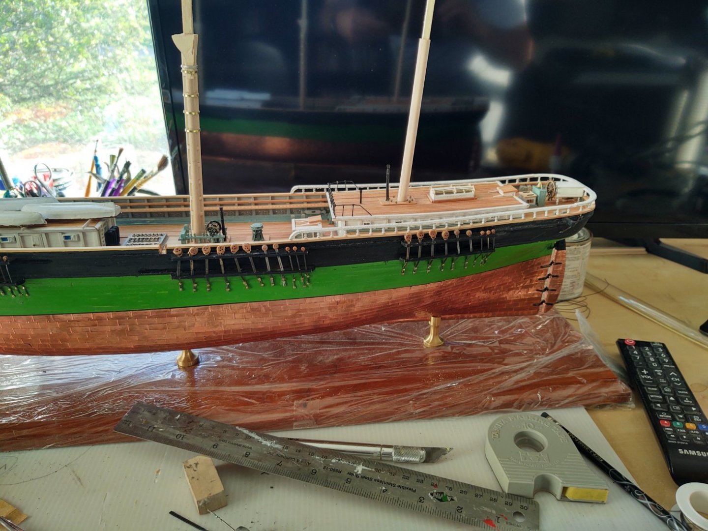
While that has been going on I've been continuing to work on the masts. As you can see in the image below I've added the cheeks to both the fore and main, and have begun putting on the mast bands prior to painting. I had thought about having the mast bands be black iron, but the available evidence (the Butterworth and Chinese painting) all suggest that the bands were painted with the lower masts, so white they will be. The main isn't fully banded yet because I ran out of brass of the right size - however, I got an email about an hour ago from Model Shipways indicating that they are shipping me some additional brass in response to my request, so that should be resolved pretty soon. I had earlier asked about people's experiences with their part replacement policy and it appears that I am another satisfied customer.
Finally - as hinted in the above, I've been building the mast tops. The photo below shows the fore and main, more or less ready to mount on the cheeks. The mizzen just has the two laser cut pieces, I'll get it soon enough. The holes for the fairleads and the futtock shrouds are already in place. The real ship has an iron band on the outer edge of the upper side of the top, which I will add once it is painted. I'm debating using pre-bent 1/32 square stock or some 24 gauge black steel wire. The steel wire is about 1.5" at scale, the wood stock is 3" at scale. I'll probably try both and glue the one that looks best.
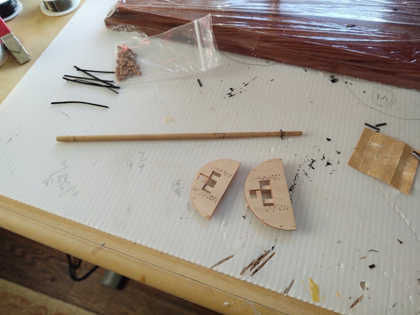
You can also see that I am working on the jibboom. It's drilled, it just needs another "iron" band and 3 eyebolts and it will be ready to mount.
So, the plan moving forward has three things going on at once - doing the chain plates on the starboard side, finishing the lower masts and tops, and starting to rig the bowsprit. I've chosen to conclude that this allows me to make progress in several areas while things are drying rather than suggesting that I have a disorganized mind and un-diagnosed ADHD. That is my story and I am sticking with it, plus I find that adding line tends to get me motivated to do more. Actually make that 4 - there are a few things left to do on the hull (a couple of ladders, lashing down the 3 ships boats, maybe emplacing the myriad belaying pins).
Anyway - thanks for looking in and for the encouragement and likes.
Regards,
George K
-
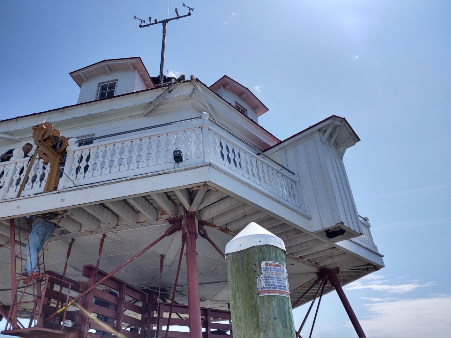
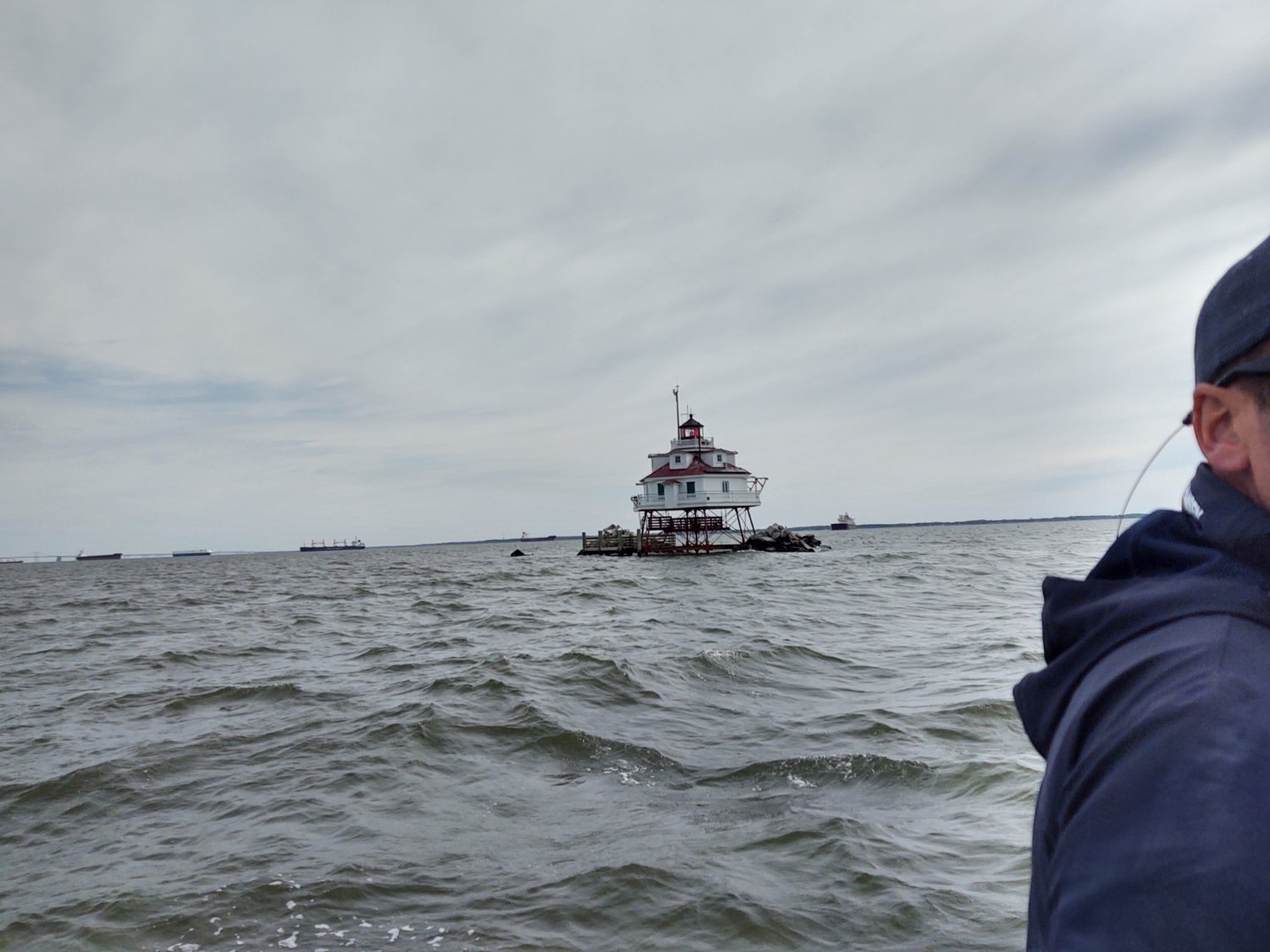
Some more photos. Not that this will surprise anyone, but the protuberance on the left is a privy. All water comes from cisterns fed from the roof which I can tell you is not free of gull excreta. it's possible that it used to be less of an issue, but they lived rough back in the day.
-
6 hours ago, ClipperFan said:
Out of pure curiosity, any idea how much of the original building is left?
Uh oh, I think we are heading into Ship of Theseus territory here, and that is not the ship I'm modeling 😀.
Short answer is I don't know.
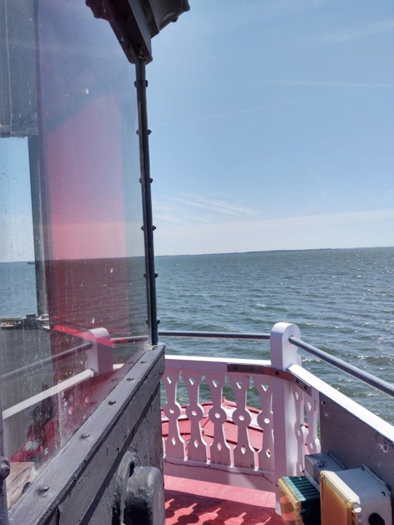
Longer answer is that the light was renovated and repaired/updated over the 111 years it was occupied. So, for example, the Fresnel lens is obviously no longer in place, and it is lighted and rotated by a set of large batteries, the weight system that used to run it are gone, the furniture is period correct if not original, etc. And, well, it's a wooden structure in the middle of the bay.
In fact, we were there that day to remove and replace the shutters, scrape the paint under the shutters and paint the underlying wood so it wouldn't get damaged while the new shutters were being cut to size (they are apparently all slightly different). We identified at least 3 or 4 pieces that would have to be replaced due to water damage when the shutters came off, so you get the picture.
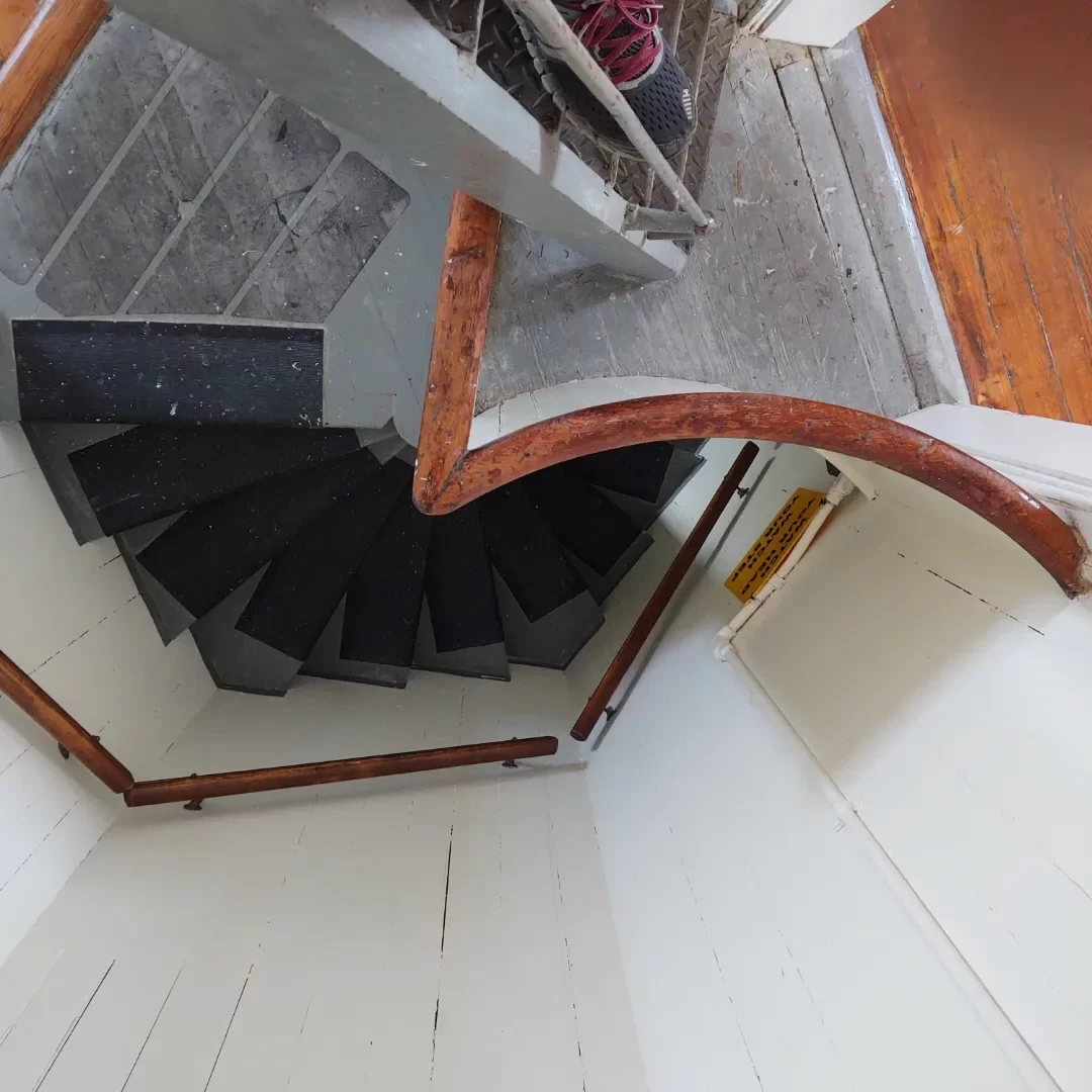
So the medium answer is probably the screw piles, some of the structural elements, and a decent amount of the interior (you can see where someone plugged the hole in the floors where the weights used to descend, for example), but I doubt much of the external cladding is original.
-
Another update coming soon. In the interim, a question and a palate cleanser.
The question - has anyone used Model Expo's replacement parts line before? I seem to be short on some of the brass - don't know whether I've just used it wrong or if there wasn't enough. I sent an inquiry via the 'missing parts' page. Recognizing that I'm not sure why I'm short, I let them know that I'd pay for the brass, but the strip is not available as a separate, purchasable item from their catalog. I haven't heard anything since - do they usually respond, just send the parts, ignore everything? I've vaguely heard good things about this, so the radio silence is a surprise.
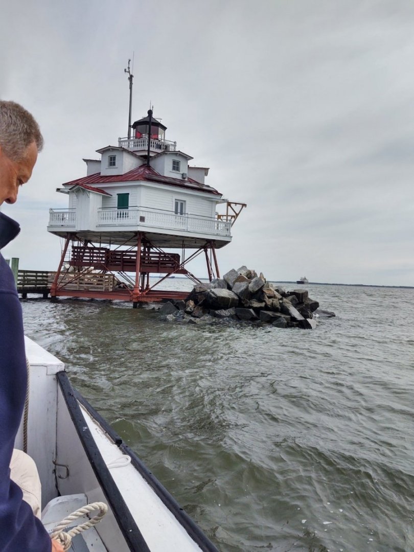
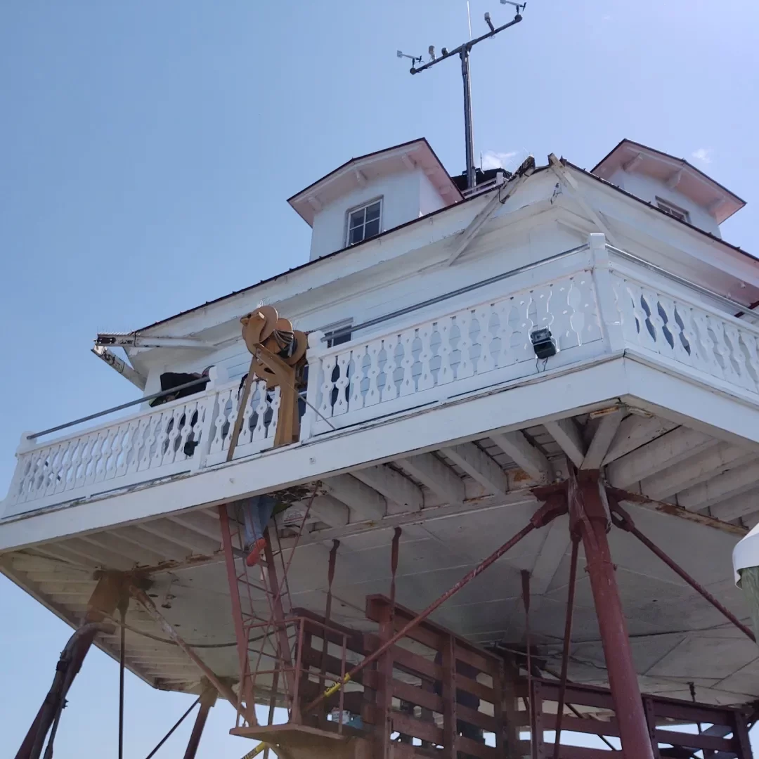
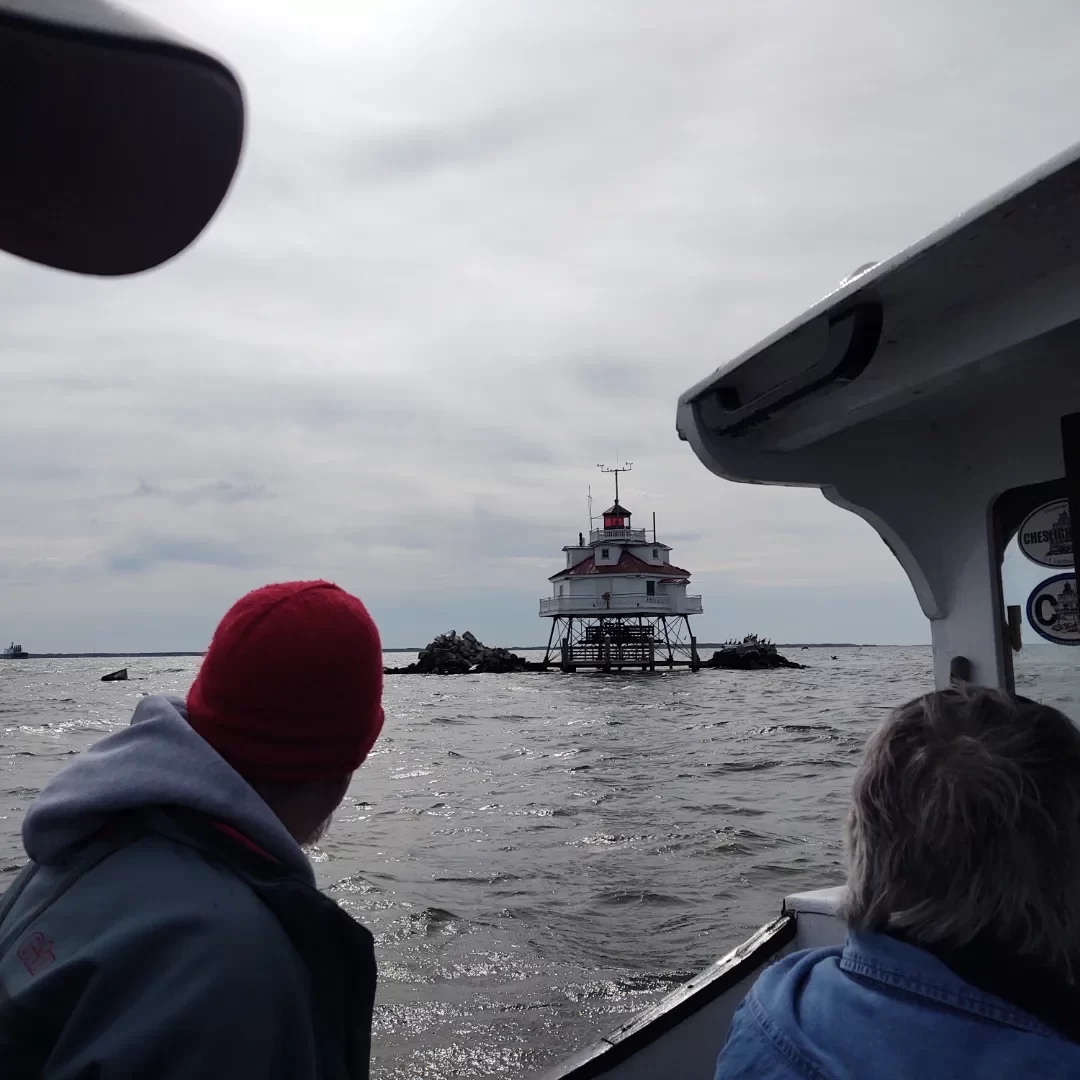
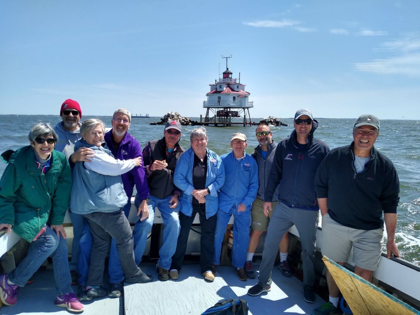
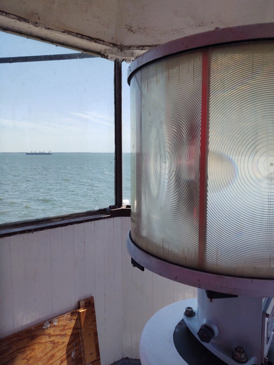
The palate cleanser. Over the weekend I was fortunate enough to spend a day doing restoration/maintenance on the Thomas Point Shoal lighthouse in the Chesapeake Bay off of Annapolis, MD. Built in 1875, accessible only by boat, it was the last manned lighthouse on the bay, not being automated until 1986 (!). Just a couple of snaps of the lighthouse and the gray haired rogues gallery that went out to work on it. The boat is a wooden Chesapeake Deadrise that started life as a crabber.
Hope everyone had a great weekend,
George K


-
3 hours ago, campbewj said:
Peeling the backing off, if you don't keep the foil side straight, makes little marks across the foil. While I've become better and limiting this, some is inevitable and I've simply accepted that.
The markings will disappear a bit as the copper tarnishes and they give the plates a bit of surface interest, suggesting the nails that are there without putting in a bunch of giant out of scale dots. That's my story and I'm sticking with it.
Bottom line is that it looks great, keep on rolling.
George K
-
4 hours ago, bcochran said:
I think they were holystoned meaning scoured and whitened.
We had a once around on this topic earlier. Royal and US Navy ships holystoned into the 20th century in ships that had wooden decks, but given the small crews compared to similarly sized warships it seems less likely that the decks of commercial vessels were regularly holystoned. Even in British naval service by the mid-19th century it was being done less frequently (2-4 times/month) and the US Navy banned it on the battleships b/c it was wearing the teak decks down at an alarming rate.
-
On 3/30/2022 at 6:31 PM, rwiederrich said:
I see what you’re saying. The taper removes the chapeling .
Rob
I had the same problem in the beginning with the MSW kit. The problem (I think) was that I misread the MSW plans. I concluded that the core of the main and fore masts were 24 inches (1/4" at scale), which was also the size of the square top of the lower masts. However, more careful reading of the plans suggested that the square top of the main (at 1:96) should have been 1/4", the square top of the fore 3/16", and the core on both the masts should be 3/16". Once I built the masts up on a 3/16 core, the tapering didn't remove the chapeling and the masts looked right. I had to then build up the square top on the main by sheathing it with some 1/32" wood, but it was a minor issue relatively speaking to resolve.
This may not be what is happening in your case but it's something to maybe think about.
Looking awesome, BTW. I loved how you put the bars on the carriage house windows. I put some on my Fish, but they were nowhere near as clean as the ones you made.
Regards,
George K.
-
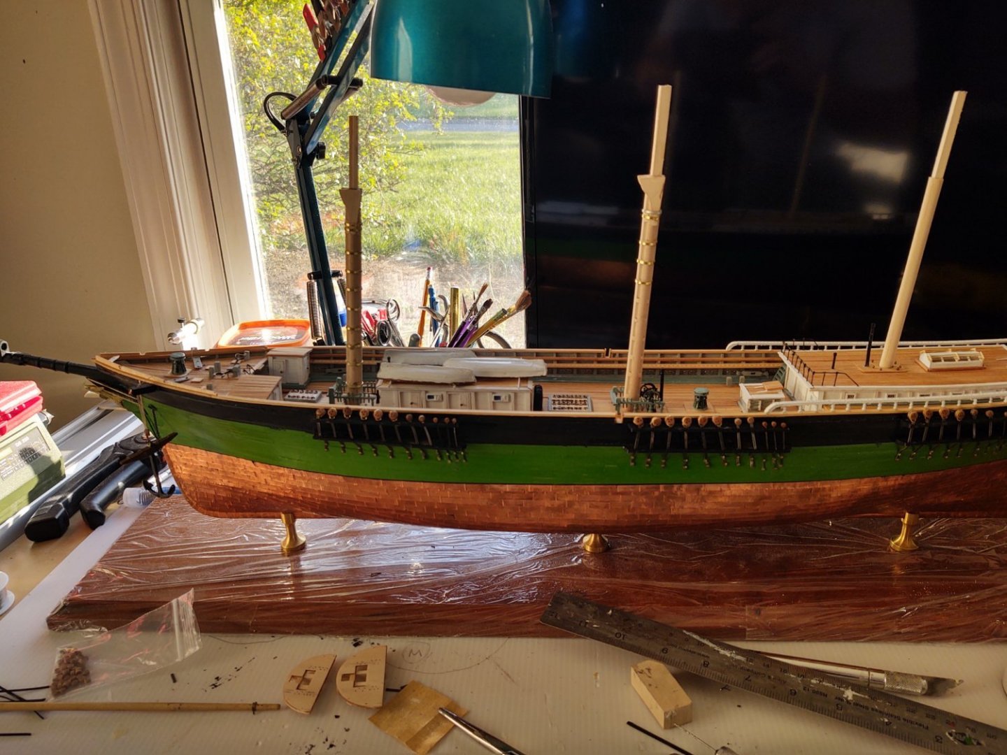
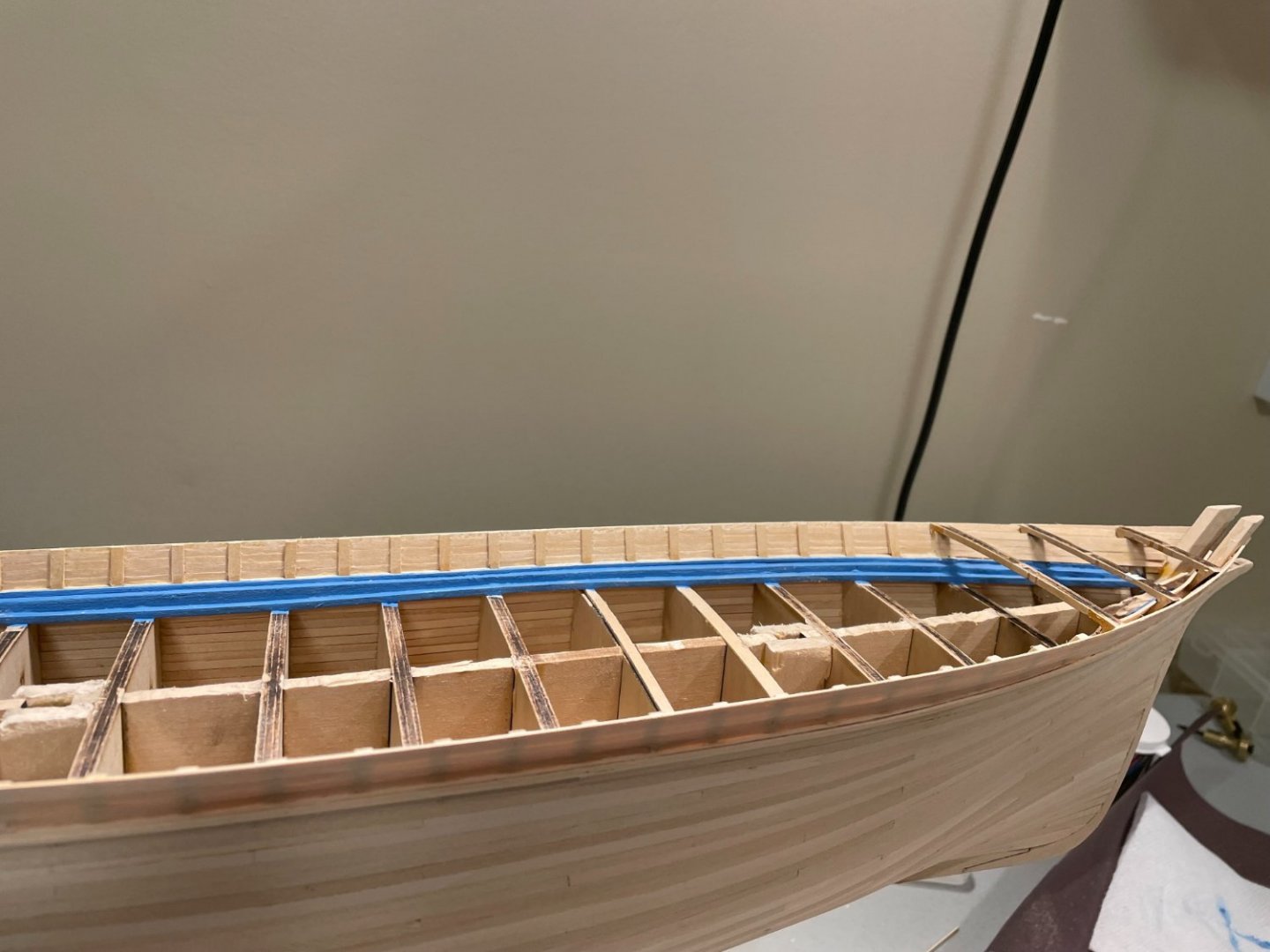
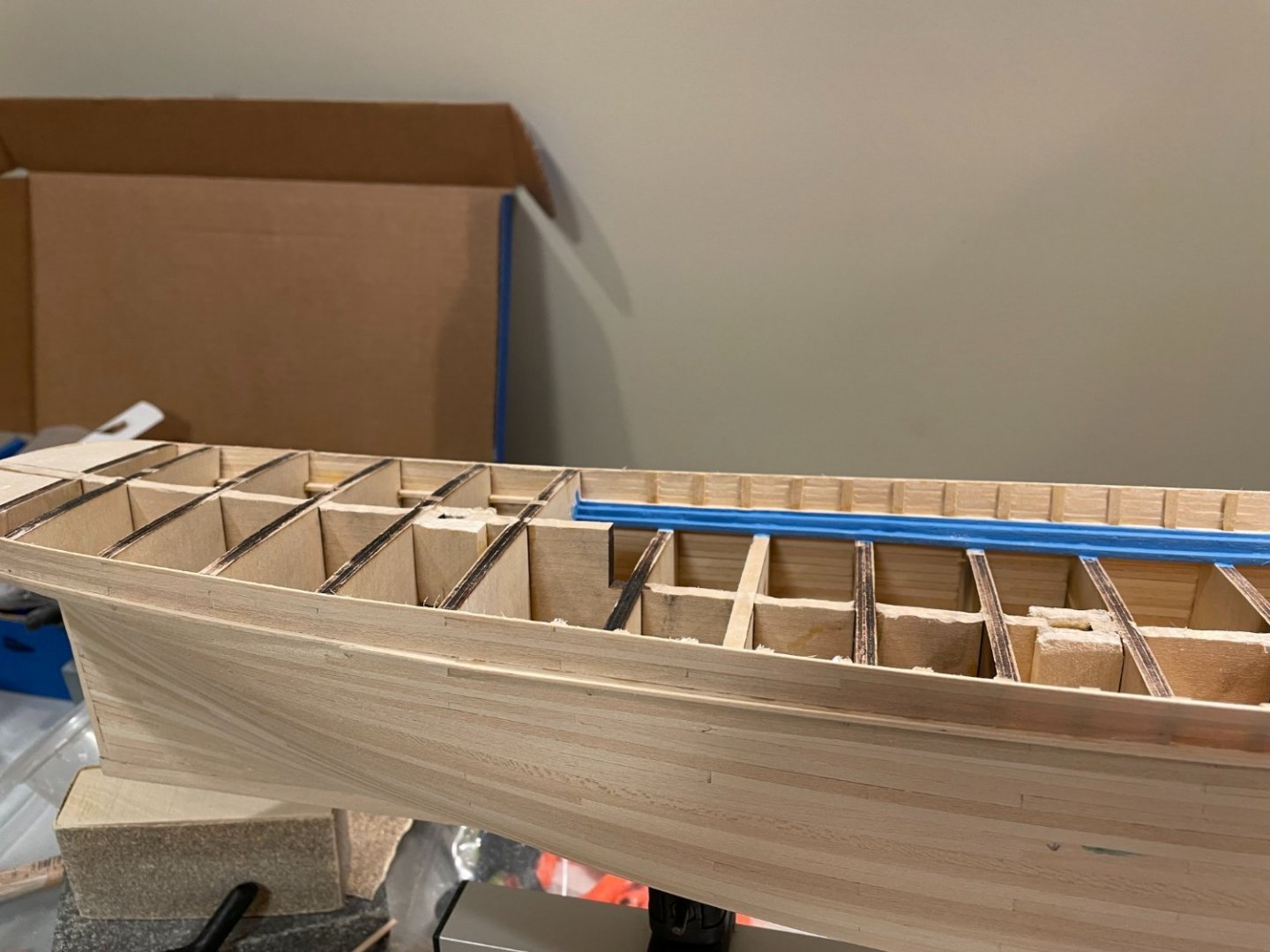
It's been about 3 weeks since I've done an update. A combination of things has slowed everything down, ranging from some extra efforts needed with work to training for the Cherry Blossom 10 mile race that was last weekend. As I age, the miles take longer and cost more. Plus, for some reason making the chain plates has been something of a blocker for me.
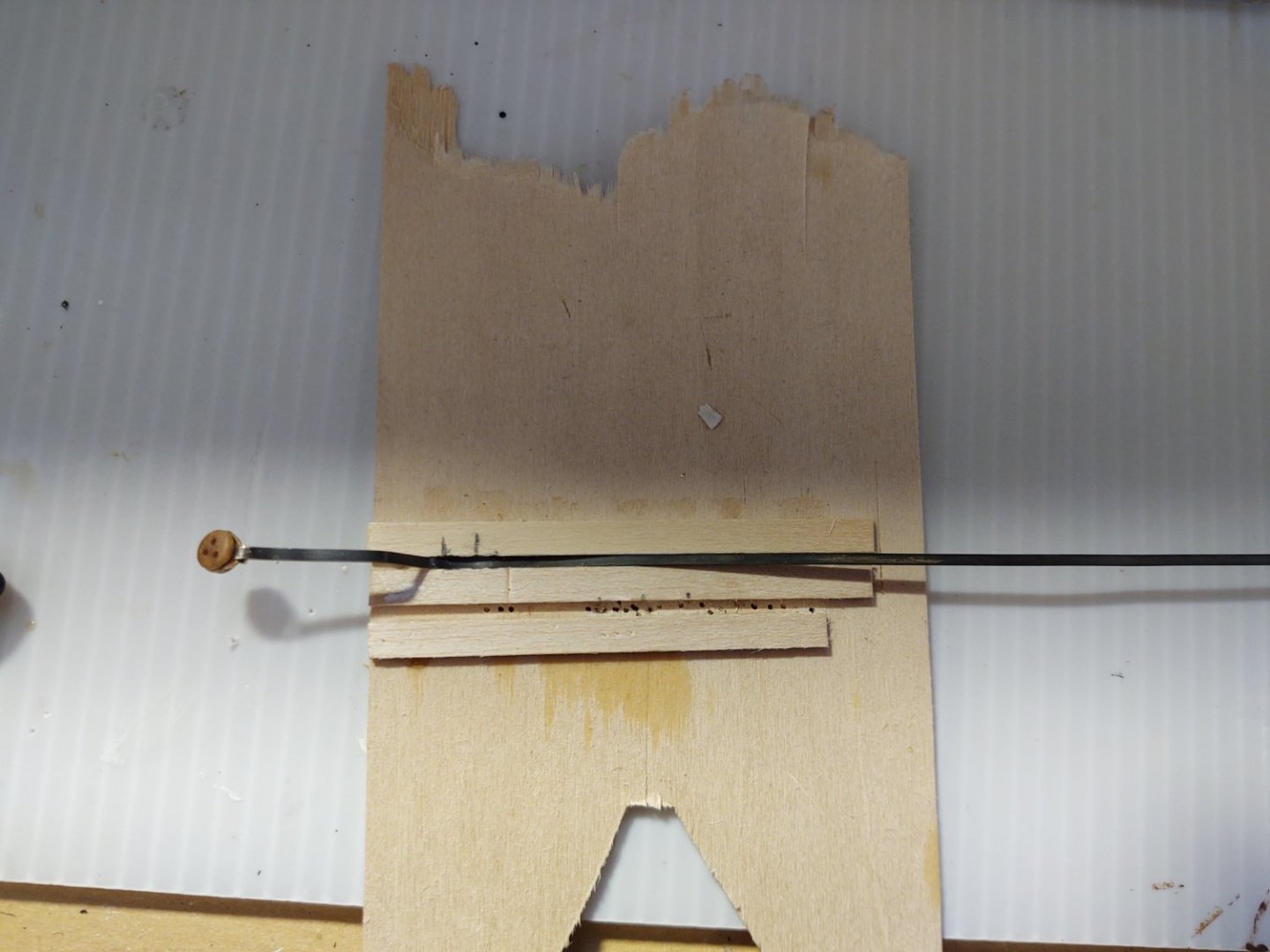
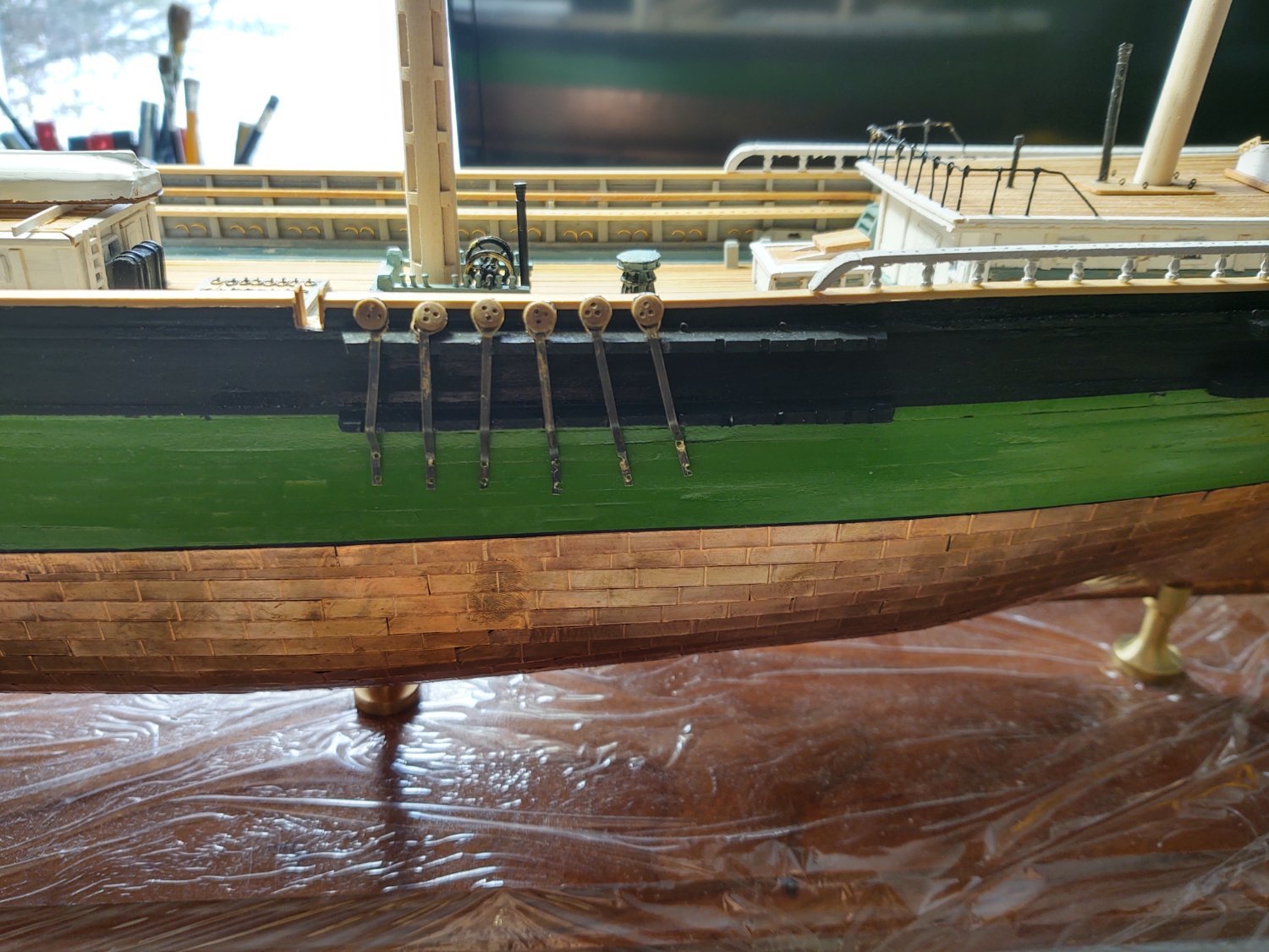
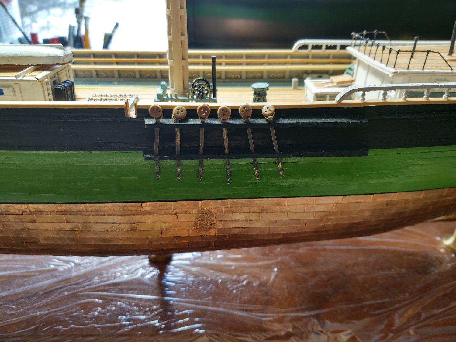
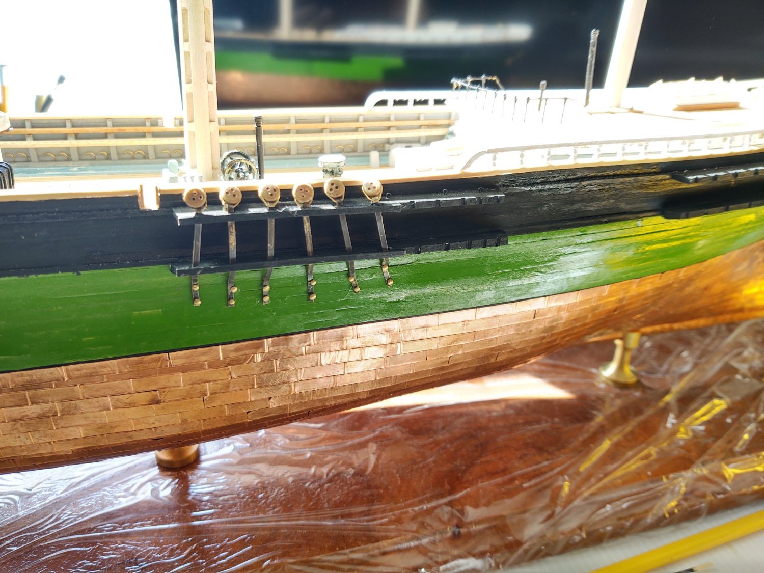
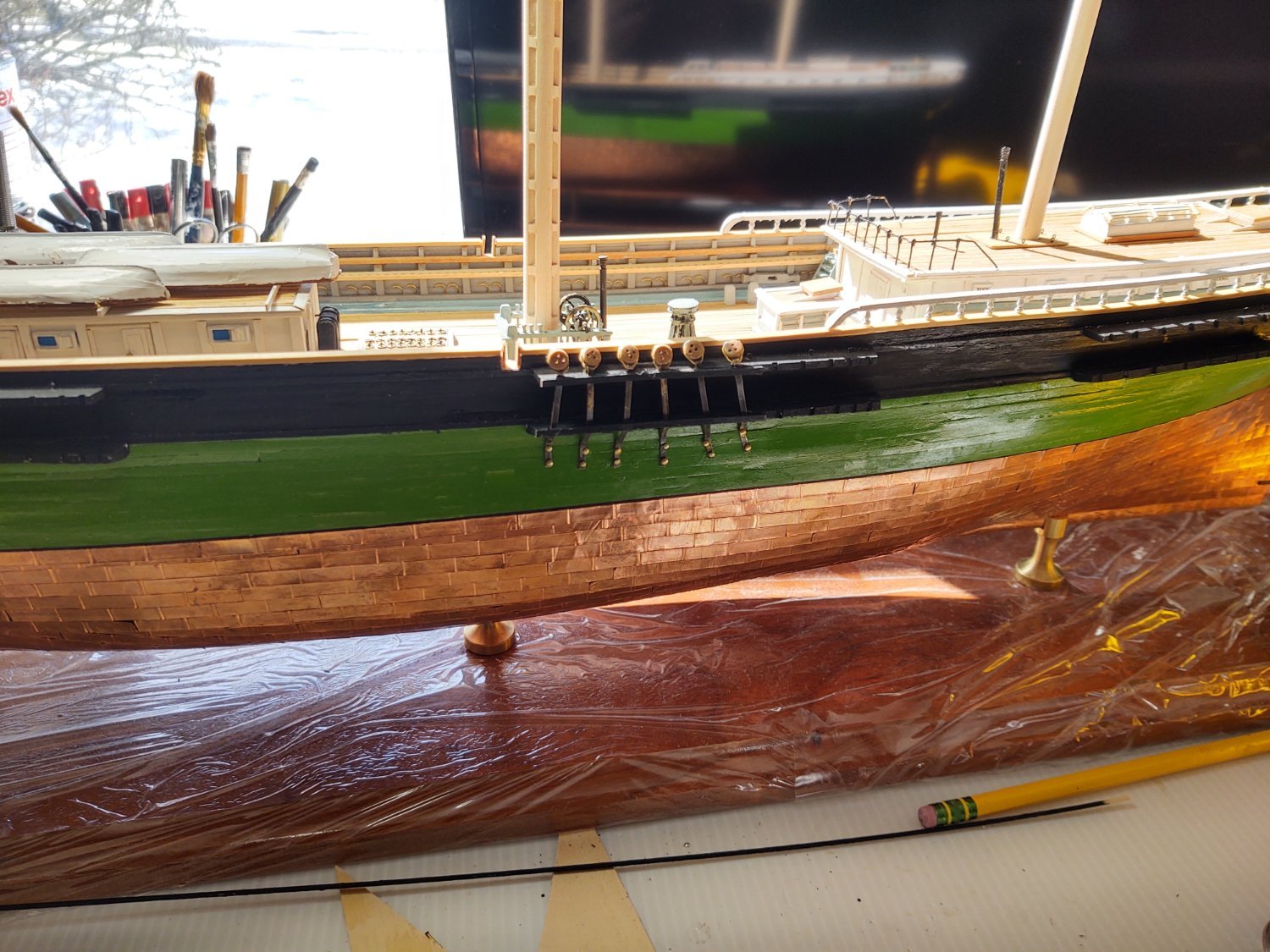
As I mentioned in previous posts, there are three sizes of deadeyes attached to the chain plates for all three masts. The largest deadeyes use 1/16" wide brass strip which is wide enough to drill for the nails that are representing the bolts. They are 6 inches at scale and that seems about right for the size of the deadeyes. I'm using 1/32" wide brass (so 3" at scale) for the smallest of the deadeyes (these are for the backstays in the upper works). They seem right but I don't have either a drill press or other obvious means of cutting holes in the strip to push the nails through. I've worked out a method for dealing with those (more anon). There seemed to be no intermediate size of brass strip available for the lower backstays. However, @MrBlueJacket from sent me a small test strip of 1/16 by 1/64 Britannia strip. Even though it's the same width as the brass, it just looks different and somehow right for the intermediate size chain plates. Once my order arrives I'll start on those.
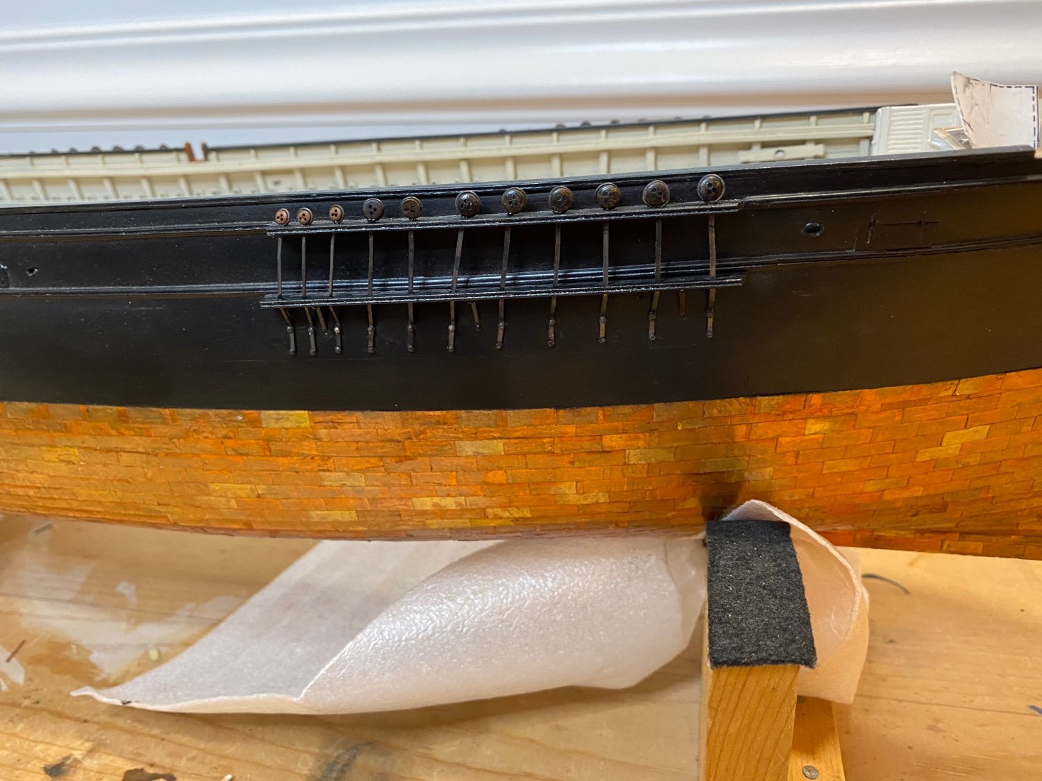
The pic above shows the chainplates on the port mizzen. The four large ones are in place, and the three smallest. What I wound up doing was stropping the deadeyes with some 34 gauge steel wire and then bending the 1/32 brass strip through the strop, covering the area where I wound the strop with the bend of the brass (if that makes sense). Then I put bent the brass, installed it in the channels, and cut it off where I wanted the top "bolt" (i.e. the nail) to sit. I used a bit of CA glue to attach the bottom of the plate to the hull. I then took a 5 mm strip of blackened 1/32" brass that represented the preventer and glued it to the hull about 1 mm from the bottom of the plate, and in line with the direction that the plate was facing. I could then drill two small holes, one between the plate and one below the "preventer", and glue nails into the holes. It's not perfect, but I think it works.
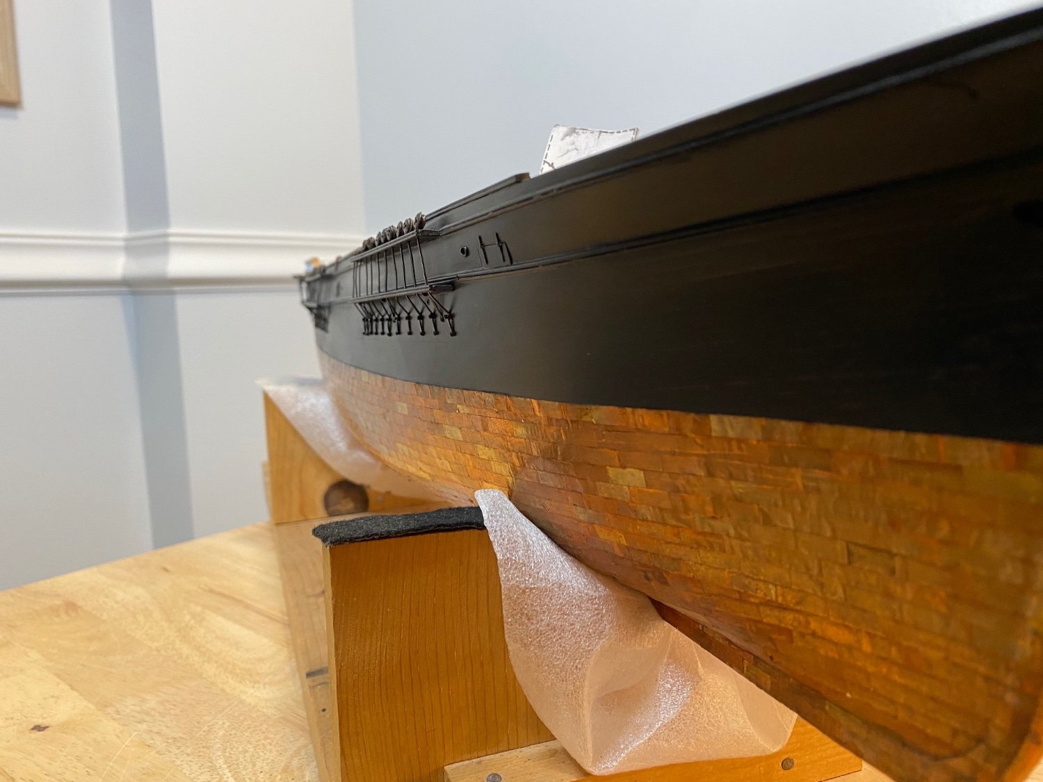
Where I am now with the plates is that I've done all of the shroud plates on the port side of the ship and the first three of the upper backstays. There are 6 lower backstay plates and another 6 of the upper backstay plates, but having worked out how to make them all, I feel more confident about moving forward. I expect to display the starboard side, so this was the "practice" side, and I've learned some good lessons for when I move to the other side of the ship. Below is a (terrible) photo of where she stands now. I couldn't get the light right, the point is that the chainplates are coming along, if slowly.
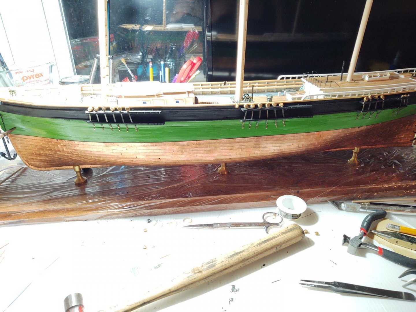
I've been doing some other steps as well. I've been adding the mast hoops to the fore mast, and will move to the main once that is done. I've also started fabricating the mast tops, that will be coming soon. I added the ladder from the main to forecastle, which I am oddly, and perhaps strangely proud. The ladder is a bit chunky (that's what happens when you don't use the fittings, I suppose), but what I'm proud of you can see in the photo below. I made the railing out of chain and 4 jackstay eyebolts. I don't know if the real ship had chain railings, but somehow I thought that they might, so I took some of the rigging chain and attached it to blackened eyebolts. As an aside, you can see the lowest of the mast hoops in the photo as well (all the paintings show the masts as painted white (including the hoops) so they are going on prior to painting.
As always, thanks for looking in!
Regards,
George K
-
1 hour ago, ClipperFan said:
Finally, the actual rail which surrounded the rear quarters of "Flying Fish" still exist today. Apparently her Captain Simeon Jones repurposed these components for use at his Mansion at 490 Main Street, Centerville (Cape Cod) Mass.
Wait, what? You mean the rail on the roof of the carriage house, or the taffrail? The Fish was wrecked in China, the Captain brought home parts of a rail to put into his house? Where were they incorporated?
-
9 hours ago, Rick310 said:
Those are actually copper strips .02 at 1/32 width that I cut on the Byrnes table saw . I used a center punch and hand drilled the holes with a #75 drill bit per EdT modified to my limited ability and lack of experience. The other chain plates are3/64 wide
The plates on my Fish are 0.03 x 1/16. I will see about some 3/64 strip for the smaller ones.
-
59 minutes ago, Rick310 said:
I believe that these are brackets supporting the lower channel. These are shown on the plans for the flying fish.
As you say, they are on the plans for the lower channel. I'm going to put them in once the rest of the plates are on. Am I seeing correctly that you switched to smaller brass strip for the last three stays? I may need to buy some intermediate size strip for those as I don't think I can readily drill a holes a hole in the narrow strip from the kit
-
52 minutes ago, Rick310 said:
Note brackets under the chain plates


Concur with @rwiederrich that is nice looking.
-
On 2/10/2022 at 12:42 PM, Vladimir_Wairoa said:
after finishing davits, and deck working stuff First i will next focus on footropes , have to think what i want to achieve what i am capable of and im not sure what i can do. i read that vertical strings are better made of wire as they keep it in place and not twist than rope...decisions decisions.
I've used thin, black wire from BlueJacket for the vertical footrope components. I found it was impossible to make thread hang right. Not that this is the consideration, but it is way easier to make the loop with wire than with any kind of thread.
-
On 2/22/2022 at 11:58 PM, rwiederrich said:
Thanks Ian. I worked this design out with lots of experimentation. It is tiny metal work, but it pays off.
Again, thanks for commenting.
Rob
How are you making those blocks, if you don't mind my asking - they really are nice. Sorry if I missed this somewhere, if so, please point me to the correct post.
Regards,
George K
-
Some interesting progress on the Fish. After my error described in the last post, I made 32, 18 mm circumference wire loops and fitted them to 32 of the largest deadeyes, pushing the wire into the channel in the deadeyes and leaving a rectangular section at one end to insert blackened brass strip that will become the chain plate. Actually, I probably made more like 60 of the loops, as, in the process of fitting the loops around the deadeyes and forming the attachment point, I think I snapped one for every one that was successfully manufactured. Nevertheless, they are made and ready to start installation.
I had cut the chains according to the patterns on the plans so that the chainplates will align with the shrouds. This meant that each plate would have to be of a different length in order to ensure that the bottoms of the preventers would run (more or less) along the same line. So, I measured the distance between the lower chains and the top of the preventer off the plans and put a piece of Tamiya tape on the hull so that the top of the tape is where I wanted to upper bolt on the preventer to end.

(it's about 6 mm). I then took a deadeye with the brass strip attached, fitted it to the correct pair of cutouts on the chains, and carefully bent the brass strip so that the it would hit the hull at the top of the tape. I then put the bent deadeye/chainplate into a jig to hold it in place, and carefully drilled two holes 4 mm apart. (the lines are 4 mm).
I did this for the 6 chainplates the hold the shrouds (in this case for the port side main mast) and marked them with tape so I'd know which is which. Next I removed the tape and used CA glue to attach the 6 chainplates to the chains, but didn't glue where they attach to the hull.

From there, I glued a pre-painted black strip over the two chains, since the plates are not on the outer edge of the chains, but rather pass through. I only covered the shroud plates at this time, as I will need to do something similar for the backstays.

Finally, I used a pin vise to drill holes in the hull for the bolts, and used small nails dipped in CA to secure them in place.

It's not perfect, but this is the 'non-display' side and I suspect I will get better as I go. It is definitely better than I did with the Niagara, and I think that the concept is generally sound. Here is another view:
I also built up the core of the lower mizzen mast. It is solid, not built, but I turned it more or less the same way I did the other masts because it struck me as easier to wind up with a nice square core where the top will live rather than trying to cut out a square from round stock. Anyway, I think it looks nice.

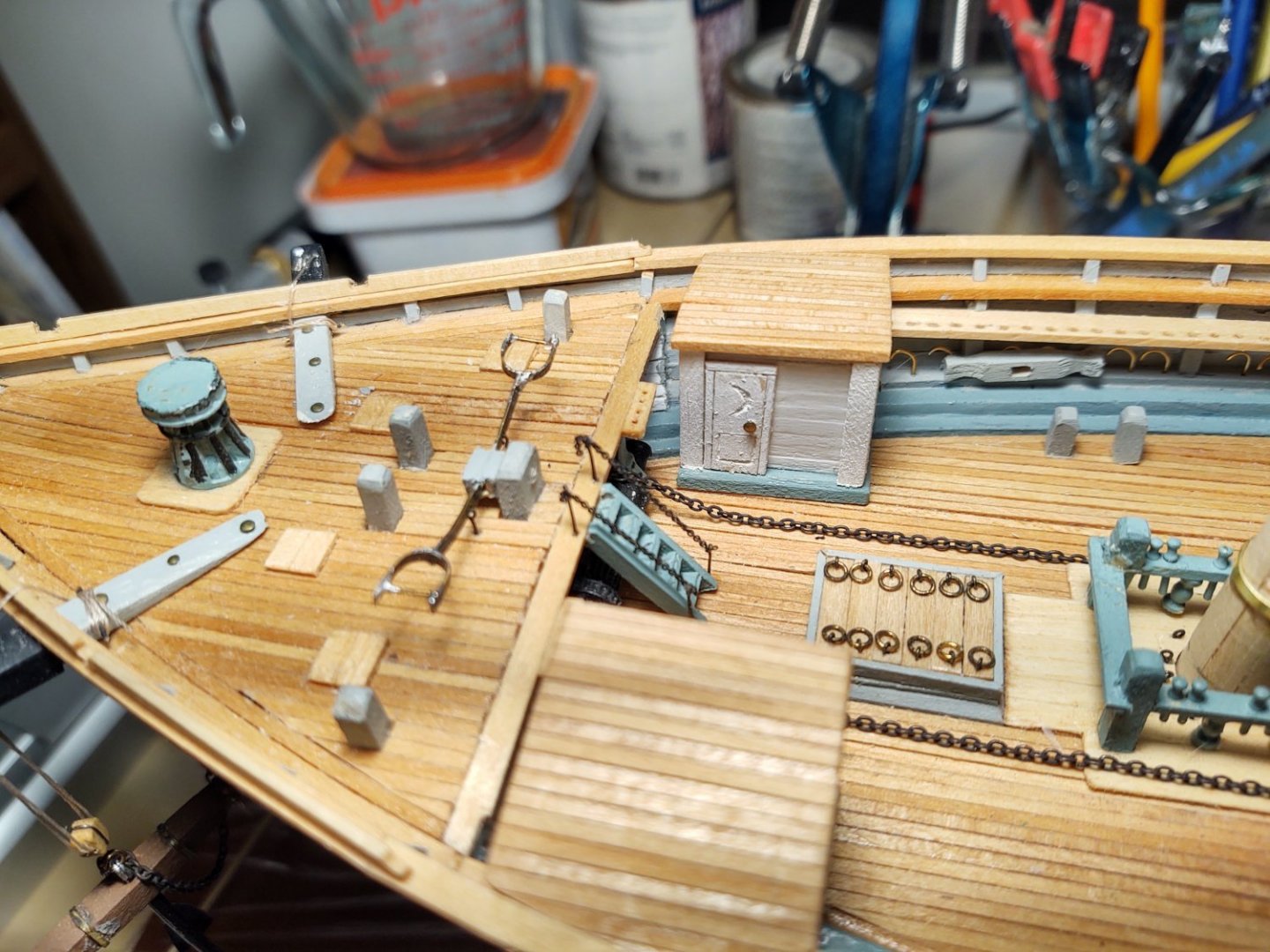
One question. I've been detailing and painting the ship's boats, and I was wondering about how standardized the loadings of them would have been. The plans say to set all three boats on the deckhouse with the boat bows facing forward. They would seem to 'pack' better, with more room on the the roof of the deckhouse if the cutter and the Captain's gig had their bows facing aft and the longboat had its bow facing forward. One of the boats needs a bit of touch up before I mount it, but I would be curious if anyone has any thoughts here.

As always, thanks for looking in and the encouragement!
Regards,
George K
-
On 3/11/2022 at 1:40 PM, ClipperFan said:
Jared I reviewed the Butterworth piece and see that in the stern area, where lifeboats are on davits, they're both stored face up while covered with canvas tarps. Meanwhile the ship's launch on the large house abaft the foremast is stored face down. This also appears to have been the practice on "Glory of the Seas." There are also photos which verify this procedure.
I don't know that I would call these boats "lifeboats". While they certainly would behave as such in an emergency, they are more properly "Ship's boats", used for all sorts of workaday functions. According to the plans, the three boats on the deckhouse are a longboat, the captain's gig, and a cutter. I imagine that for many tasks the crew would go to the long boats on the davits first, but, these were working boats, they must have been pulled off periodically or (to quote Long Jack from Captains Courageous) "they would be overboard". Given the small crews and passenger loads on vessels of these types, I'm guessing that you could get everyone into the two 24' longboats on the davits in an emergency in any case, without worrying about difficult launches of the other boats.
As to the rig design in the plans, I'm going to speculate that it was considered too difficult to replicate the rig, and a simplified 'line over the boat was substituted so that something was there.
Regards,
George
-
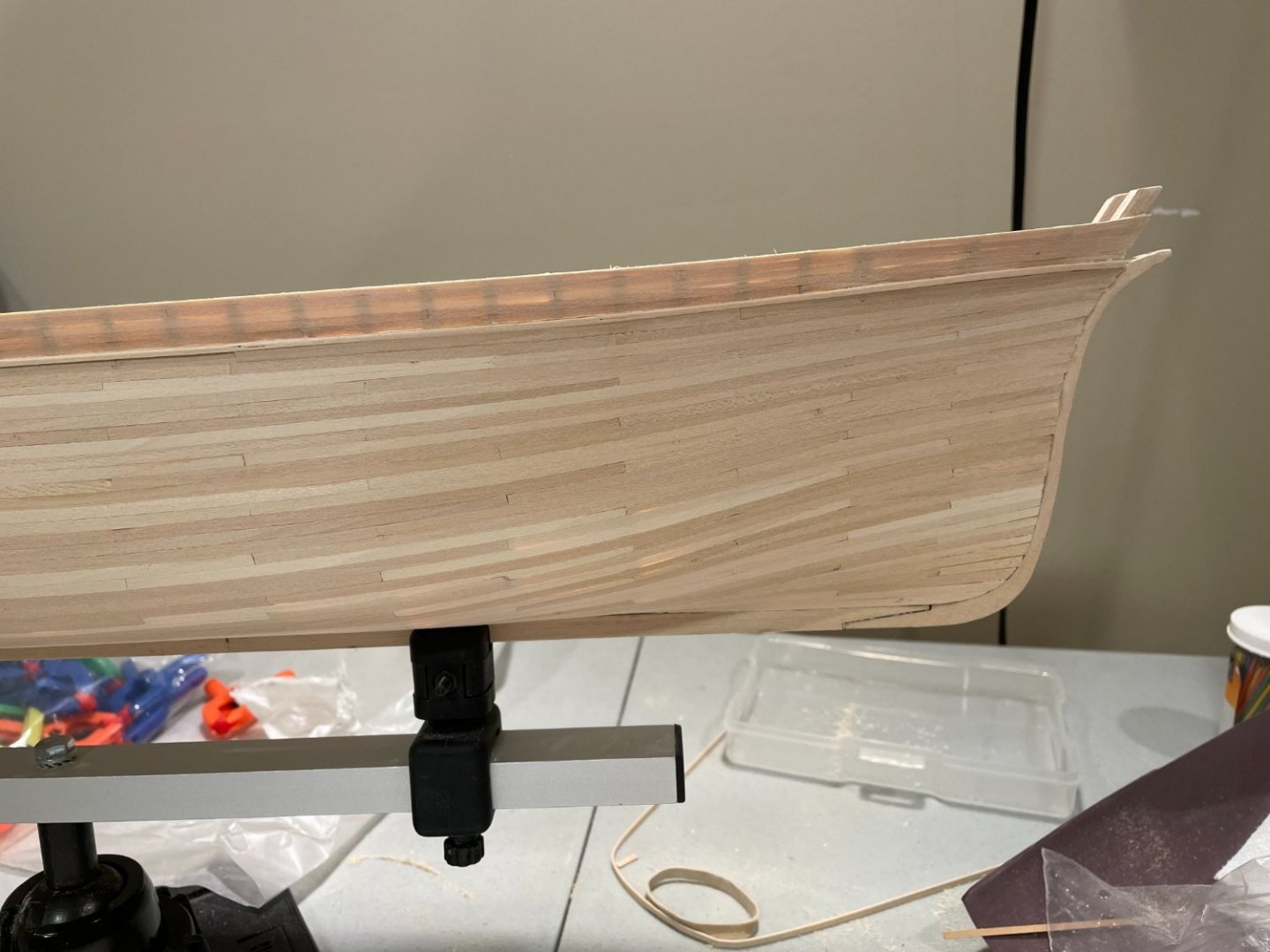
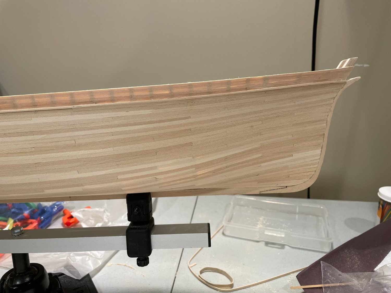
2 hours ago, campbewj said:
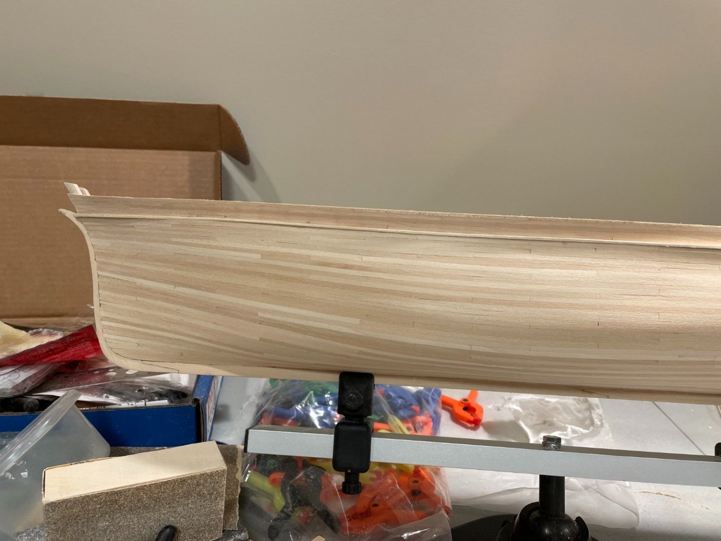
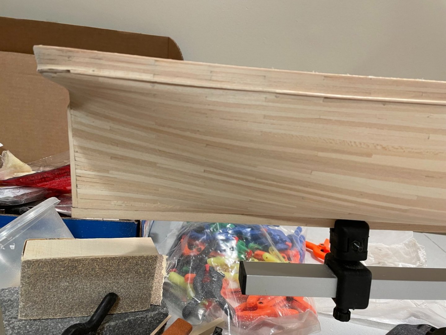
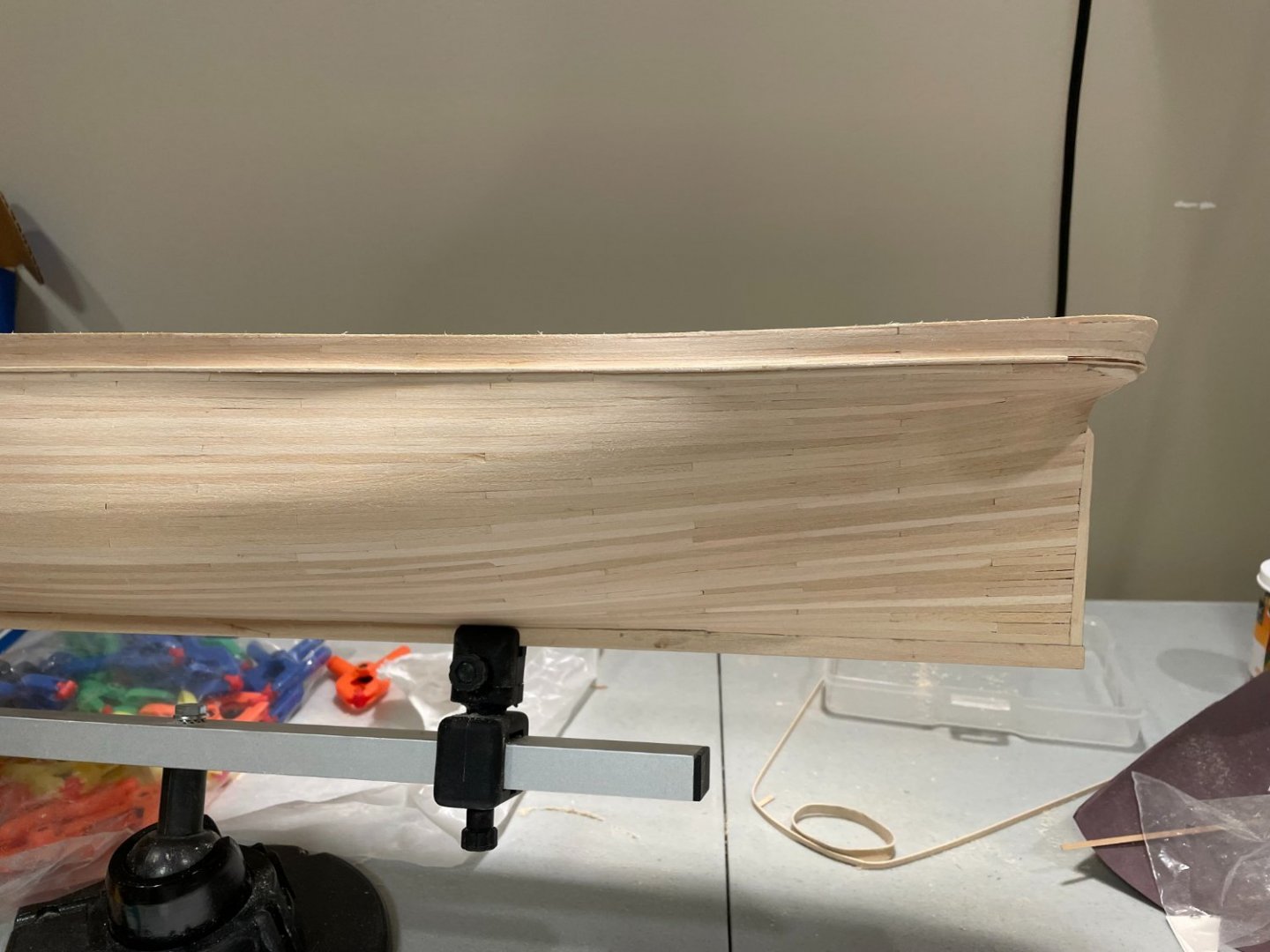
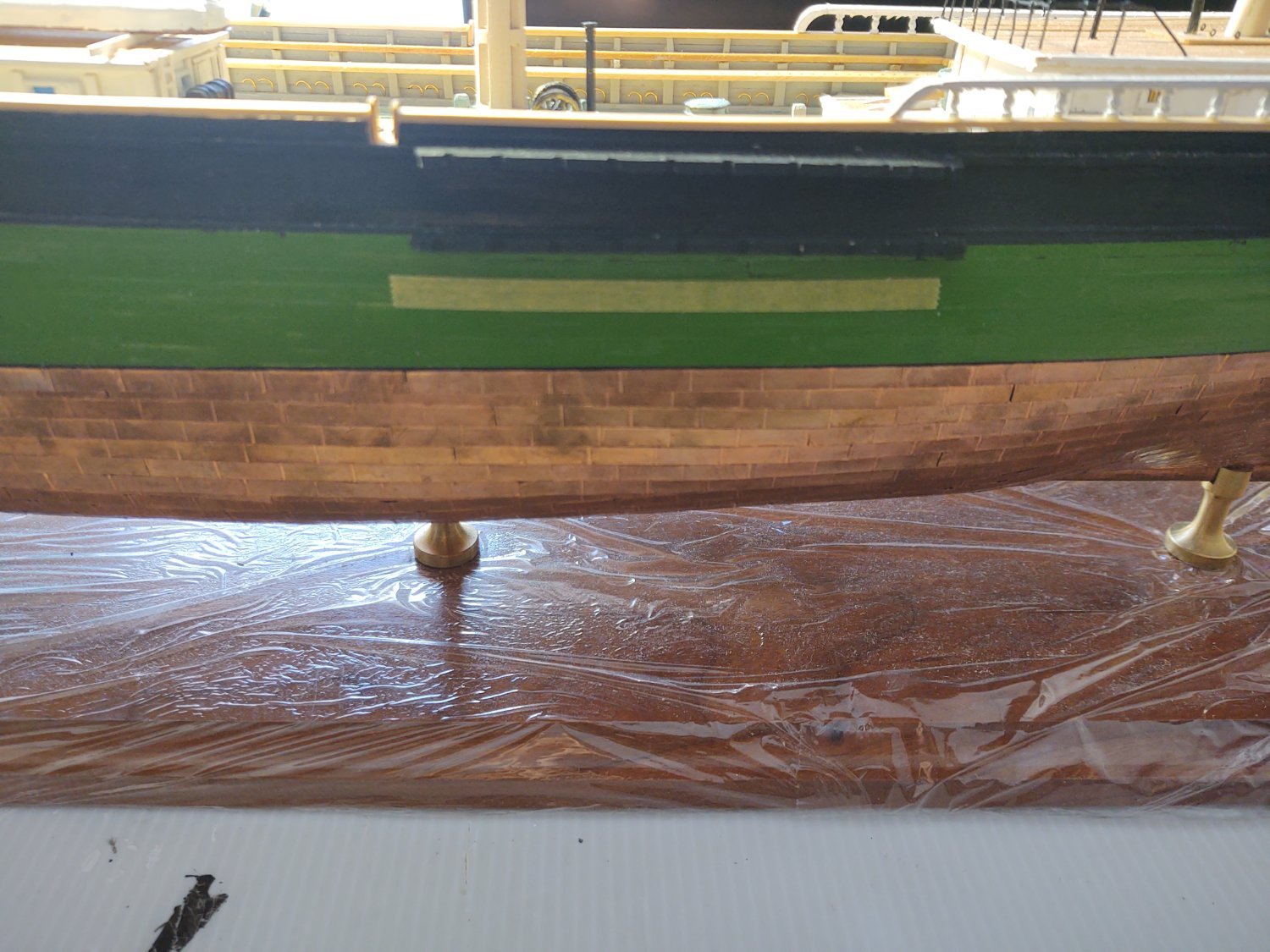
After about 3 1/2 months I've completed the hull planking. The deck is still to come. I'm thinking through some sequencing of when I want to paint. Generally I like to paint before I have the opportunity to slop paint on the next things. I'm thinking I will paint the inner hull and probably the outer hull before I put the main rail as that will be stained. Then I can copper the bottom and install the deck. Interested in other views.
One big question for those that have coppered the hull. I don't see any guidance as to how to prepare the wood to best take the copper plates. Will they adhere best to natural wood, painted wood, or some sort of "pre-treatment". coppering looks like a lot of tedious work and I'd hate to have them fall off because I didn't prepare the hull properly. State of the mode can be seen in the pics below
Looking good!
I painted the hull before I completed it, partially so that any small errors wouldn't show through as much. It used utterly conventional Tamiya flat black XF-1 acrylic on the area that was going to be coppered and things have adhered just fine.
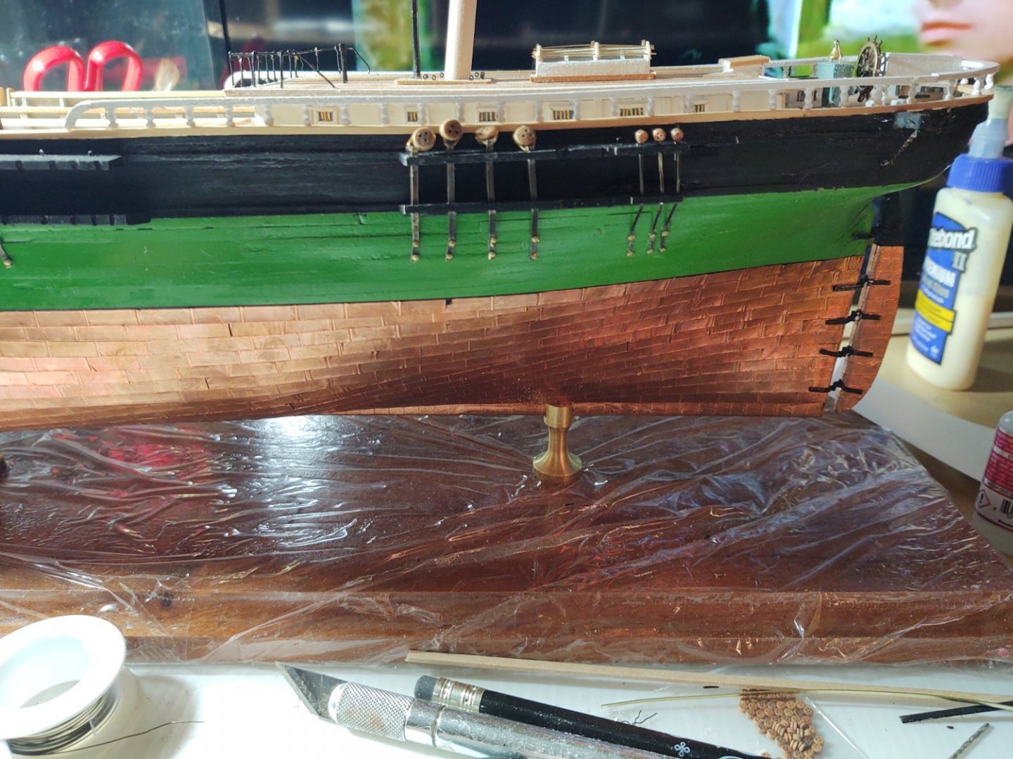
What I would do is throw out the kit copper tape and replace it with 3/16" Venture Tape (you can get it from places that supply stained glass artists). I used black backed tape so any slight peeling wouldn't show. It adheres better than the kit tape, looks better, and is more in scale than the 1/4" stuff from the kit.
Regards,
George K


Cutty Sark by Bruma - Revell - 1:96 - PLASTIC
in - Kit build logs for subjects built from 1851 - 1900
Posted
Impressive Captain!