


gak1965
-
Posts
608 -
Joined
-
Last visited
Content Type
Profiles
Forums
Gallery
Events
Posts posted by gak1965
-
-
1 hour ago, BrianK said:
Understood George. I am suddenly reminded of the episode of *MASH* where Frank and Margaret want a bust carved of Colonel Potter. The local carpenter-turned artist hands a piece of wood to Frank as a sample of his work. Frank says "looks likes a 2x4". The artist replies as he cradles the piece: "Thank you. It used to be round." 😃
BrianK
I seem to recall the bust turned out more or less okay...
-
On 1/29/2022 at 7:25 PM, BrianK said:
Hi George,
I just started following your build and I am in awe. You describe how you "machined" the masts but the artistry still seems like sculpting to me 😃
Warm regards and thanks for sharing inspirational energy through your craft (and for sharing so many awesome ideas).....
BrianK
Thanks! But machining it is - I have zero talent for sculpture!
-
On 1/29/2022 at 6:22 PM, mbp521 said:
This is one of the reasons I shelved my build because I could not figure out how to make these look right. I was all over the place with it, down to even trying to figure out how to carve the longitudinal groves in the round stock and piecing the wedges in their locations. This method seems to work just perfectly. Definitely filing this away for the future. Thanks for the tutorial.
-Brian
I'm certain it will look awesome when completed from what you've shown of the build so far, and the amazing skill in your USS Cairo.
-
11 hours ago, Vladimir_Wairoa said:
Briań, no need to be put off, i was myself until i figured it out my way. its fairly easy and even enjoying and quick - 1 hour work even without any need of power tools. ill post method on my build. Vlad
Vlad, looking forward to seeing this other option.
-
On 1/29/2022 at 6:22 PM, mbp521 said:
I was all over the place with it, down to even trying to figure out how to carve the longitudinal groves in the round stock and piecing the wedges in their locations.
On 1/29/2022 at 7:54 PM, rwiederrich said:The first time I ever made a composite mast was for my first attempt to only cut out the chapel grooves from stock round material. The technique worked real well. Didn’t need a lathe…….just a mini table saw.
Thank you both for the compliments. The instructions suggest cutting the grooves in the round stock but that seemed really hard to me. Proof again that there are many ways to solve a problem, and it's easier if someone else (i.e. Rob) had already demonstrated the method on his builds.
-
Brief masting update. As you will recall, I made a first pass at the main mast using a 1/4 by 1/4 inch core, and 1/4 by 3/16 inch "wings" using 3/16 by 3/16 inch inserts to mimic the wedges where the mast hoops went, and that the mast was unusable because it was poorly centered. I made another pass at this as below:
The center piece on the right side has the top of the spar marked, where I will need to trim some to fit the mast cap, and continues into the chuck on the left side (which will be the end that is inserted into the deck. This yielded the following mast:
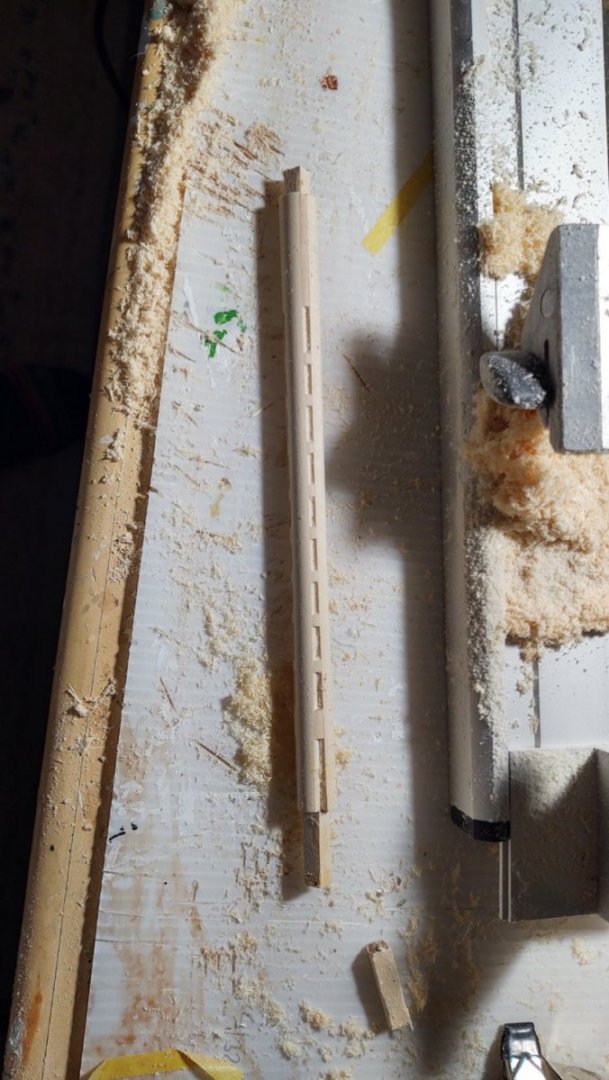
It wasn't perfect, but it seemed usable until I stupidly cut off the mast top rather than the base so that it would fit properly into the ship. In any case, even though it felt usable, I wasn't happy with it. It looked a lot like the picture of the model, but not like the plans. Looking at them more carefully, I noticed that although mast should be 1/4" square at the cap end, the core of the mast was 3/16" at scale, not 1/4". So, I took the same strategy as before, except that the core piece was 3/16" square, the "wings" were 3/16" square, and the wedges made of 3/16" square material. After lathing, I got something that I was much happier with, as shown here sitting in its location on the ship:
It's even and more obviously a built mast. I'm happy with this one, and will make the second one the same way. The mast isn't complete, I will need to sheath the core with 1/32" wood on all of flat surfaces in order to obtain the 1/4" diameter up to the mast cap. but on the whole I'm satisfied.
Incidentally, I went to the store the other day to get some more 3/16 square basswood stock and they had none. The guy at the store seemed to indicate that they aren't getting much. Big chunks of this mast were made from 3/16" square stock that I built from spare 1/16 by 3/16" stock. It turned just fine, so I will probably get rid of a bunch of such stock making the foremast.
As always, thanks for looking in.
George K
-
1 hour ago, Roger Pellett said:
Very nice work! Given the ability of the World War II US aircraft industry to mass produce aircraft, I’m surprised that the Navy expended the effort to ship these planes back home.
Having worked for the government, I can tell you if it has a serial number it has to be accounted for😀.
In any case, if I read Wikipedia right, the ship was headed in for a yard period anyway, and those planes were at worst enough aluminum for another 18 Hellcats and 8 Catalina.
-
A brief update.
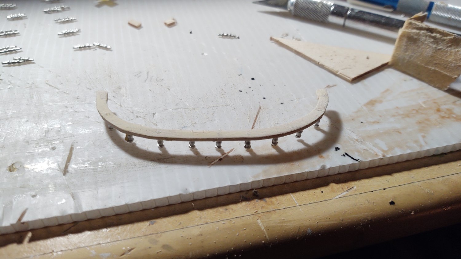
Over the last several days, I completed the taffrail, although it required making each piece something like three times. For ease of construction, I split the taffrail into 5 sections, a (roughly) semicircular stern, two straight segments that I was able to dry bend to follow the curve of the hull without problem, and two quadrant shaped sections that were the forward terminus. The stanchions are Britannia castings that had small centering knobs on both ends. I carved the after segment out of a piece of 1/16 thick basswood, and then drilled holes approximately 9 mm apart that were used to center the glued stanchions. I then filled in any gaps with putty and sanded the top of the rail as below:

You will note that the centering pin on the bottom of the stanchions have been removed. Based on my experience making the taffrail, I wanted nothing to do with drilling the topgallant rail, and anyway, trying to locate the holes struck me as virtually impossible, so I cut off the centering pins and ground the bottoms of the stanchions flat. They were then painted white and made ready to install.
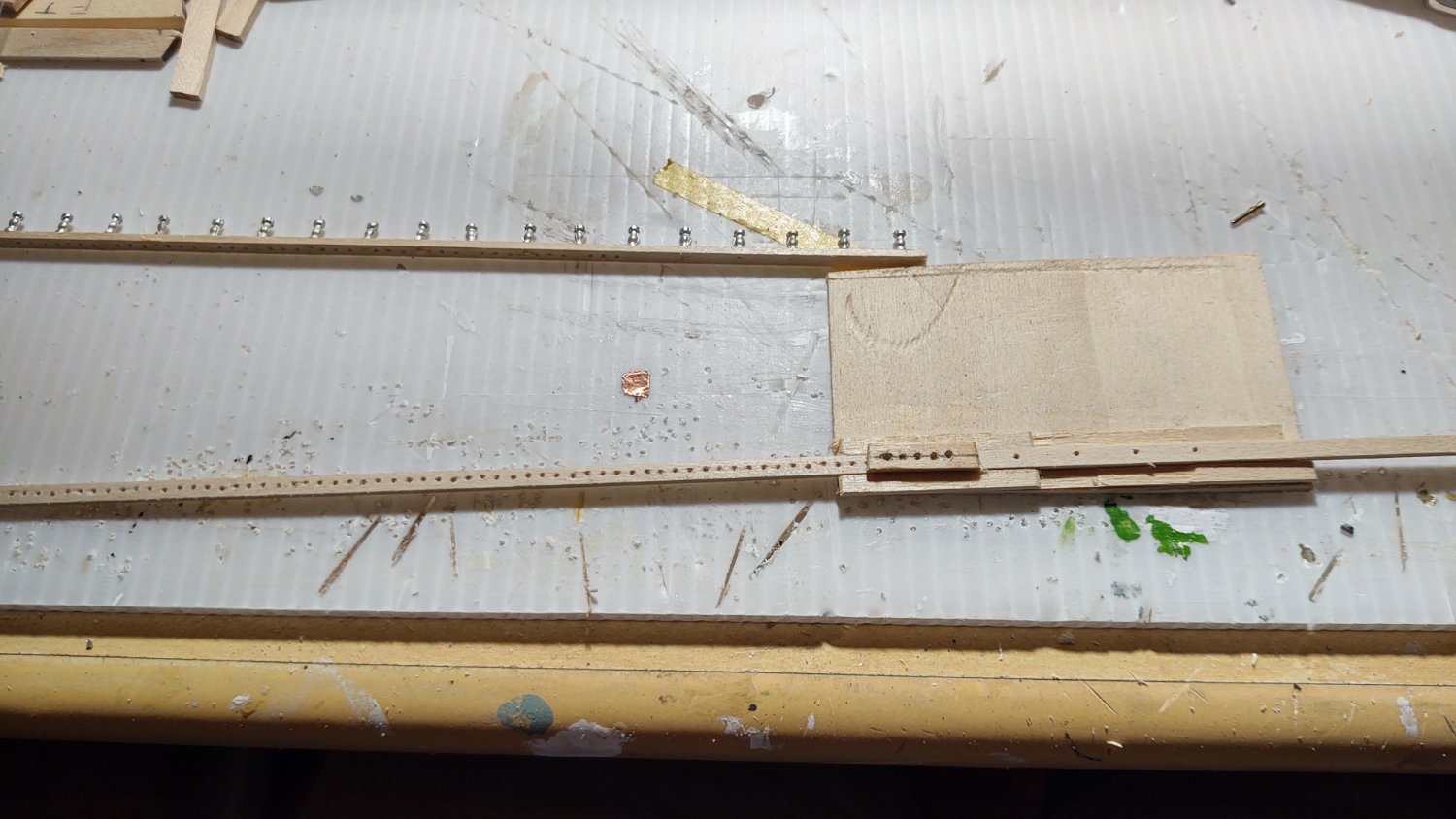
In the meantime I had to make the part of the taffrail that would have the belaying pins. My original thought was to drill holes 9 mm apart for the stanchions. After those holes had been drilled, in the sections with the belaying pins, I would move 1.5 mm forward of the stanchion hole and drill a belaying pin hole, shift 3 mm drill a belaying pin whole, and then shift 3 mm and drill another belaying pin whole, at that point 1.5 mm from the next stanchion. Locate the stanchion, rinse, repeat. That would yield a uniform row of 3 mm spaced (center to center) belaying pin holes that straddled the stanchions. Unfortunately, 1.5 mm was too close for holes that were about 1 mm, and inevitably I would get split wood. So, I made a slight change, spacing the stanchions 10 mm, and then putting the belaying pin holes 2, 5, and 8 mm from the preceding stanchion. What that means is that the belaying pins are in groups of 3, spaced 3 mm, followed by a 4 mm gap, followed by 3 pins spaced 3 mm, followed by a 4 mm gap, etc. I used the same technique (more or less that I did with the pinrails, except drilling 4 holes each time (3 pin holes and the next stanchion hole), and aligning on the new stanchion hole:

As can be seen in the upper part of the image, I installed the stanchions as on the stern, and clipped/ground off the bottom locating pin. The two quadrant shaped ends were carved out of 1/8 x 1/4 inch boxwood. Everything was painted and then installed. You can see the result below:


The groups of three are definitely present, but there are plenty of holes in the mizzen mast area. Looking at the photo, it also appears that I bent the patent vent - will need to fix that.
As always, thanks for looking in and for the likes.
Regards,
George K
- Vladimir_Wairoa, BobG, bhermann and 1 other
-
 4
4
-
To anyone that has built the Fish, it would seem like you can get maybe three holes for belaying pins on the taffrail between stanchions. That would cover like 8 stanchions, or 7.2 cm. Does that seem right to you all?
-
15 hours ago, Beef Wellington said:
I definitely fall into the non-gold camp as well...my personal opinion is that the gold actually cheapens the look of a model. I also suspect that gold paint was not used (did it even exist at this period?) and that actual gold leaf would have been the method used.
No opinion on the question of usage, but it appears gold paint called Shell Gold existed as early as the 12th Century (https://www.materializedidentities.com/single-post/2017/02/03/shell-gold-production-usage-and-handling-of-a-historical-artisanal-technique-including). Basically finely ground gold leaf in a binder.
Regards,
George K
- Beef Wellington, mtaylor, Canute and 1 other
-
4
-
3 hours ago, ClipperFan said:
George K, the only other suggestion I have for your figurehead, as far as fealty to the original has to do with her paint scheme. In his Boston Daily Atlas article description, Duncan MacLean simply wrote that the figurehead was "burnished with gold and green." In life, these lovely aerobatic fish are darker above to their midline, then lighter below. Their gossamer wings have very fine lace like veins which separate into beautiful butterfly patterns. Of course, when dealing with small sculptures, less is more, due to such a diminutive scale..
Yeah, I followed the Daily Atlas description, used gold paint and highlighted the centerline and eyes with blue green paint. Once you gild the thing, my guess is that anatomic accuracy goes out the window, and at this scale I'm disinclined to do anything more.
-
Okay. Once the first coat of paint dries, I will fill the gap slightly, but I think that this is going to be the final form of the stem.

Thanks for the suggestions @ClipperFan
- Jared, Duanelaker, ccoyle and 1 other
-
4
-
4 hours ago, ClipperFan said:
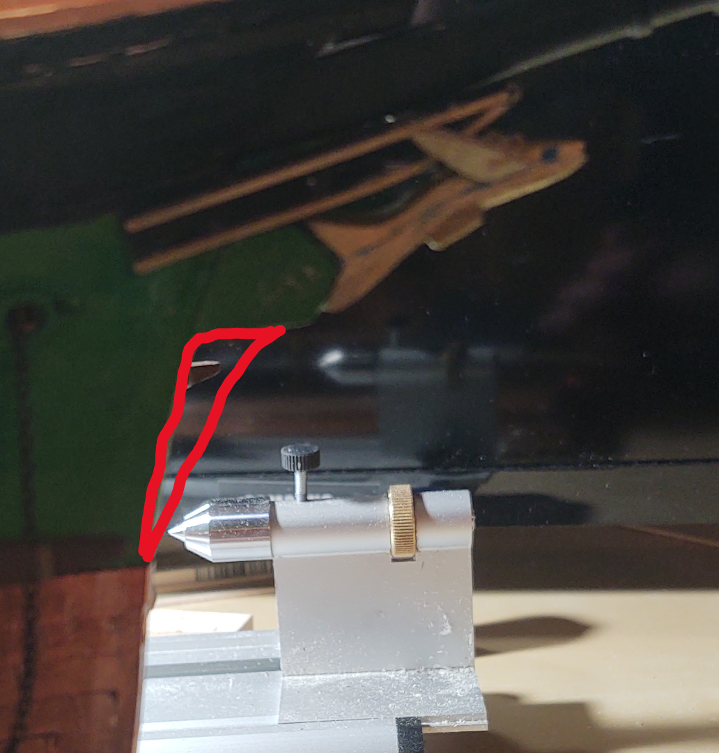
George K, nice work on representing the Naval Hoods, Cutwater & more lifelike figurehead on your "Flying Fish". I hope you don't mind a couple suggestions how to recapture a Clipper Bow. If you can, move the Cutwater up so it abuts the bottom of the Naval Hoods & extend it just enough so the fish figurehead is further up closer to the tip of the Naval Hoods. Then add the curved piece blending into the bottom of the Cutwater. I've attached a before & after sketch to show end results. Good luck!
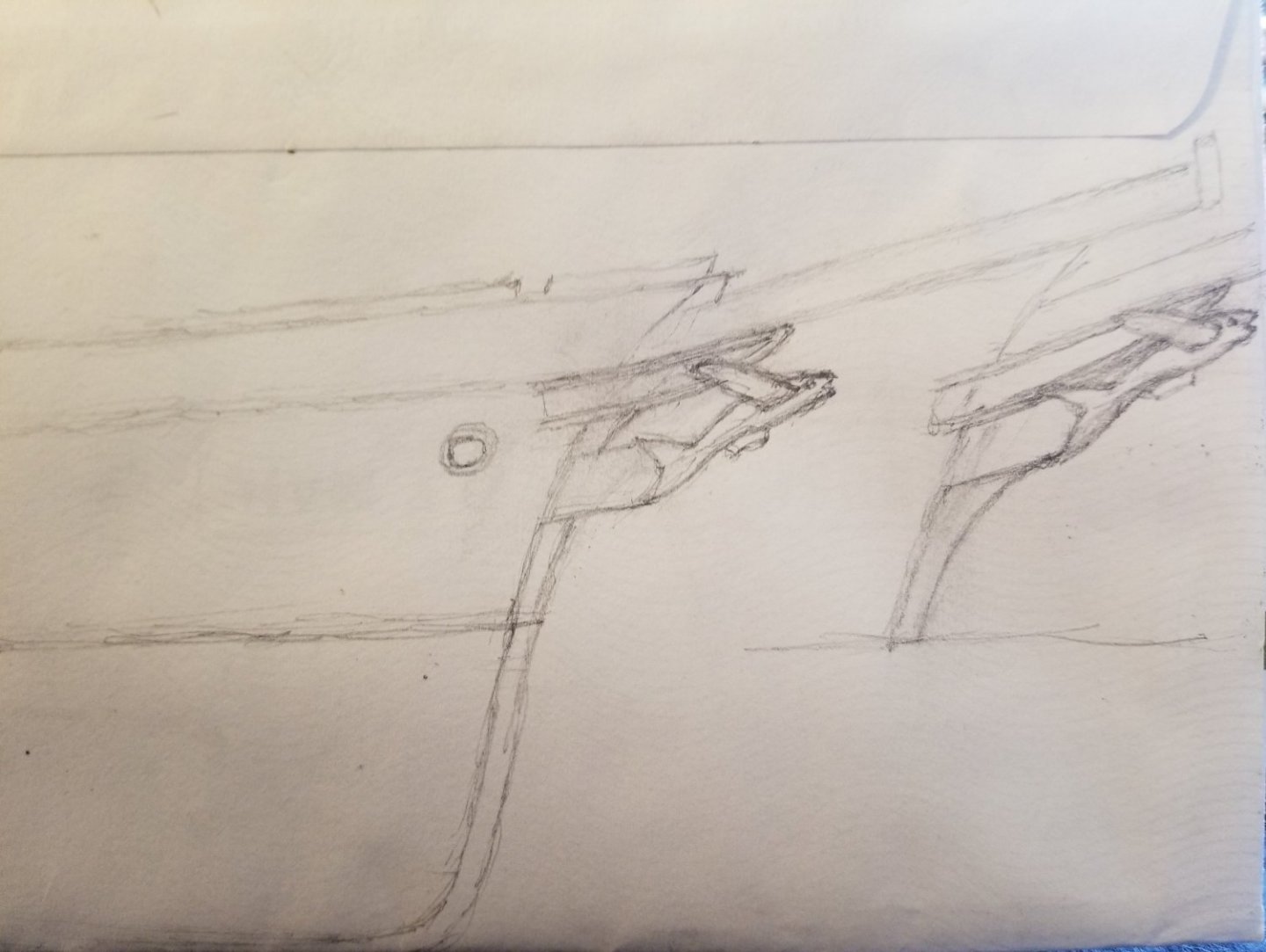
To be clearer. I trimmed the fish and moved him. But are you suggesting I extend the stem into the region shown in the red below:
-
3 hours ago, ClipperFan said:
George K, nice work on representing the Naval Hoods, Cutwater & more lifelike figurehead on your "Flying Fish". I hope you don't mind a couple suggestions how to recapture a Clipper Bow. If you can, move the Cutwater up so it abuts the bottom of the Naval Hoods & extend it just enough so the fish figurehead is further up closer to the tip of the Naval Hoods. Then add the curved piece blending into the bottom of the Cutwater. I've attached a before & after sketch to show end results. Good luck!
I understand the first part of that suggestion, but do you mean extend the stem further forward as if it is wider (longer?) than it is on the kit? To do the former, I'll need to trim down or move the dorsal fin on the fish itself (no tragedy) and actually it's not glued in place yet, so that's no big deal, but I want to make sure I'm understanding what you are suggesting.
-
2 hours ago, Roger Pellett said:
Jared,
A suggestion for your open boats- Use The Kit supplied cast boat as a form and vacuum form a new one. Vacuum forming is easily done with ordinary household stuff. A shop vacuum or even a canister type household vacuum provides the vacuum. At 1:96 scale, 1in planking is only about .01in thick so the thickness of the shell of the kit supplied boat is way over scale.
Roger
I was thinking of adding the 'planks' as in one of the prior posts and then covering the boat, so I don't have to do anything to the interior. That resolves the problem with the thickness of the shells and I don't have to make 1:96 knees on the thwarts 😀.
-
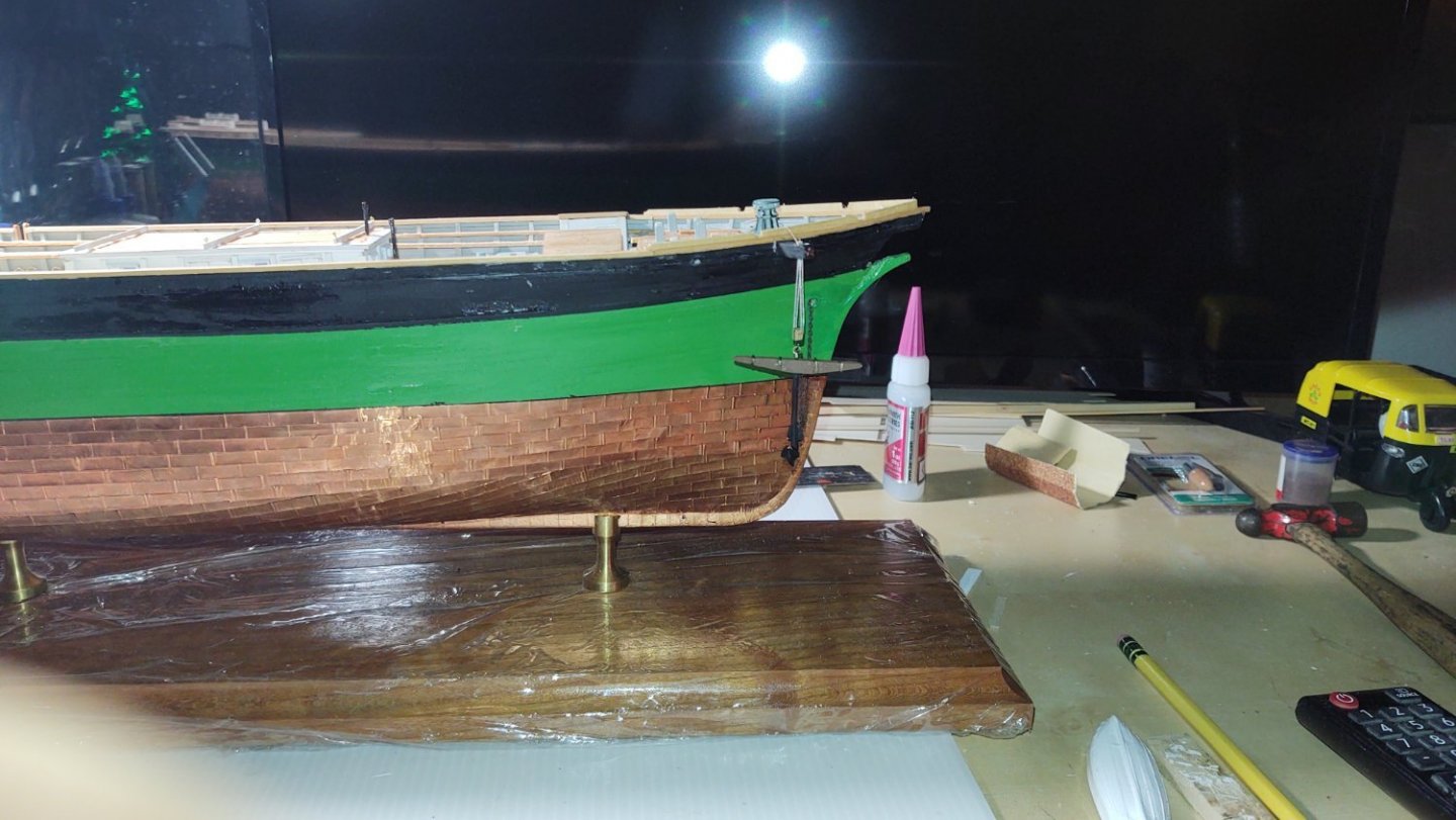
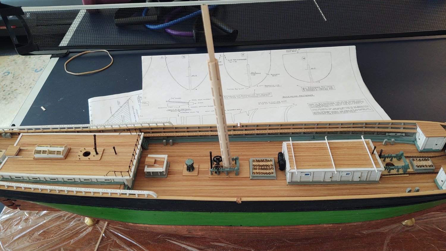
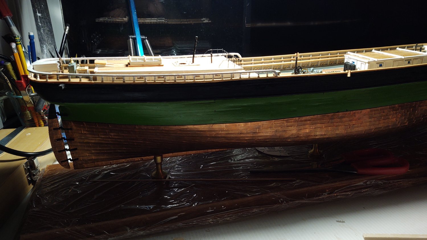
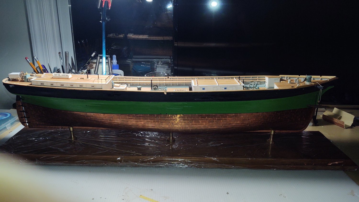
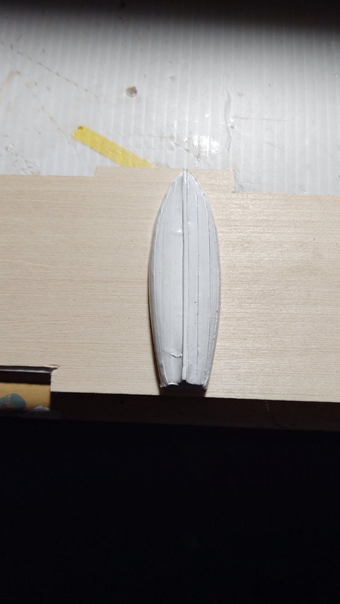
Well, in the last week or so, rather than turning masts, I've been working on a few of the items that still need to be added to the hull, although, in a sense a did turn the first spar, in this case, the bowsprit. I used brass for the iron hoops, and painted the whole thing white (as per the instructions, but it looked really odd, and the Butterworth painting shows it black, so, I repainted it black as per the two photos below:
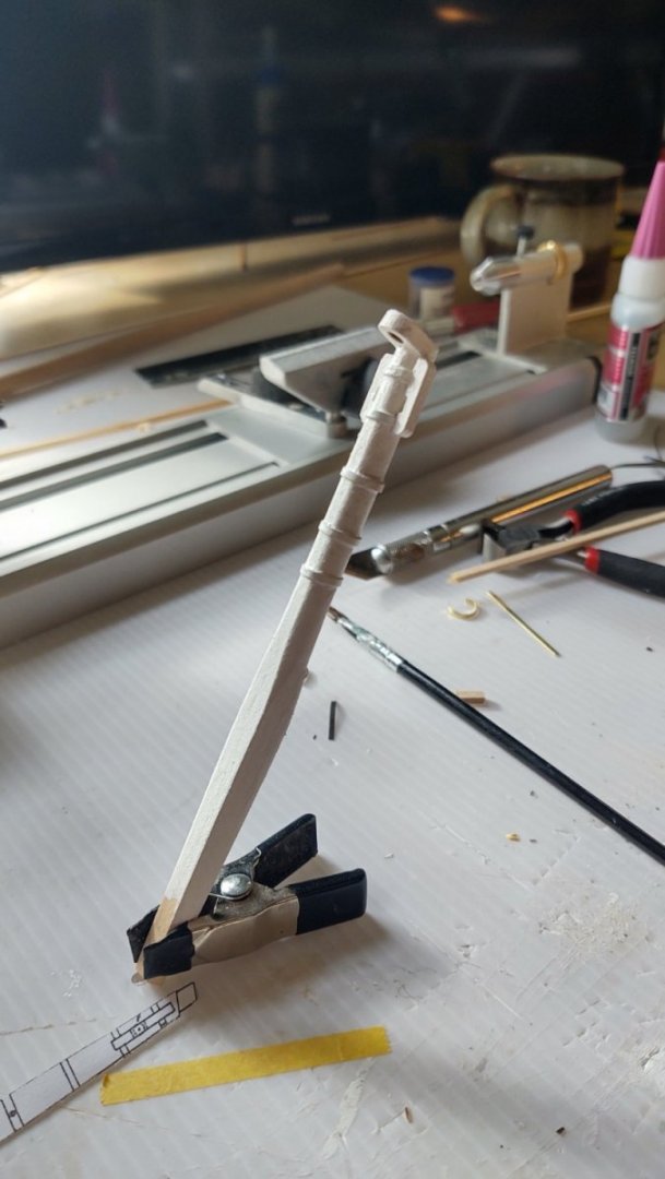

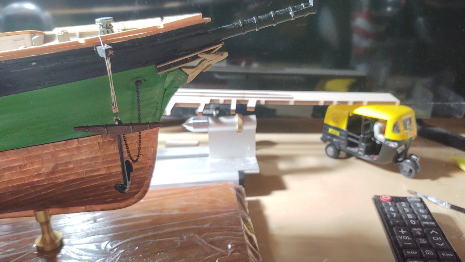
Next onto the naval hoods, cutwater and the figurehead. I used the diagrams that @ClipperFan made (both for the hoods and the figurehead) and then also examined @rwiederrich and @ClipperFan's photos of the Glory of the Seas to try to make something consistent with a McKay clipper. The results are below:
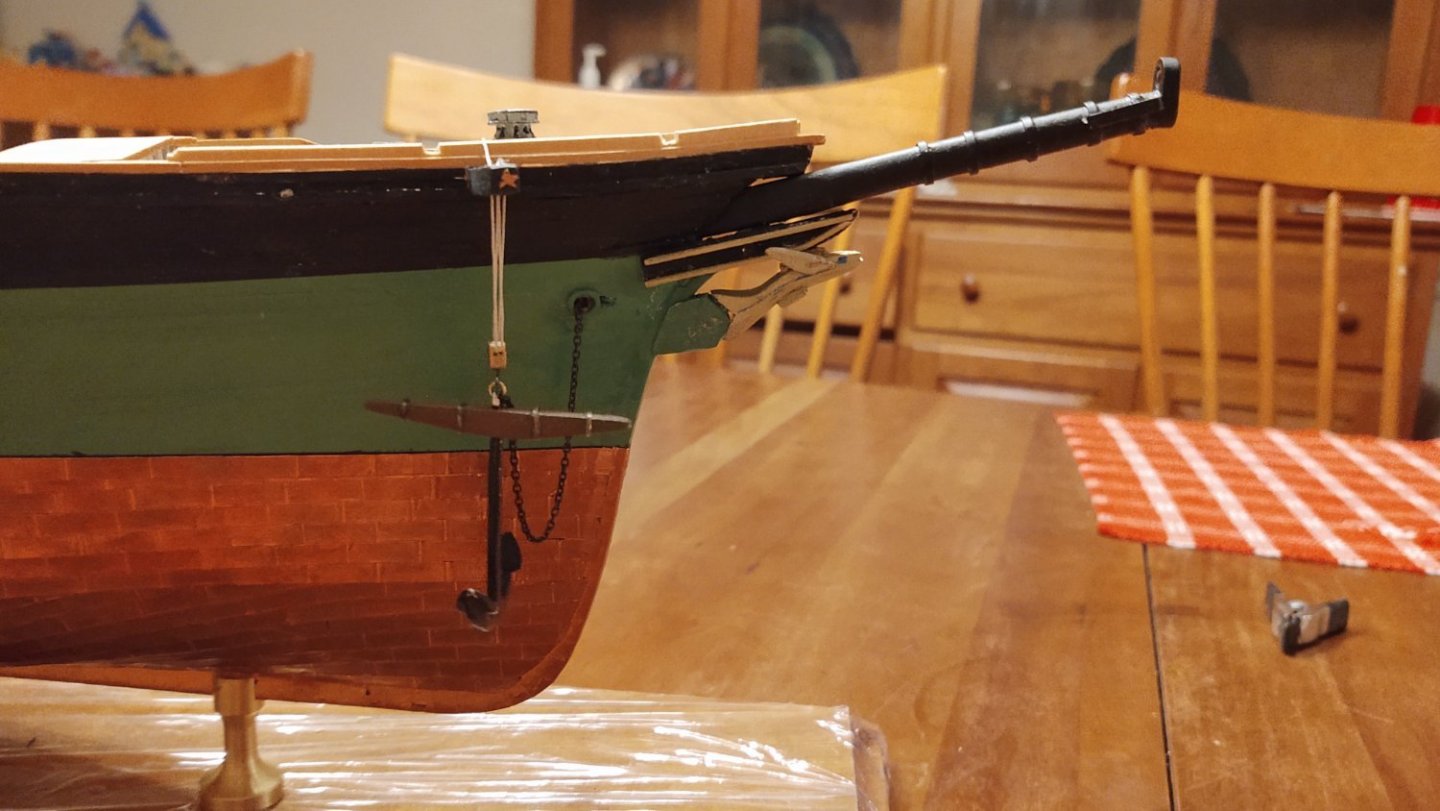

Perhaps not perfect, but I think that the cutwater looks like the one in the picture of Glory and the figurehead, even with my carving skills is much better than the one that is supplied with the kit.
In any case, the ship now looks like this overall:
I've started on the channels (they are cut to shape and sanded, but I need to locate where the chain plates are going to on both the upper and lower channels, cover the ends and paint them before installation. At that point, the only remaining hull piece that I am aware of is the taffrail. After that, there is no excuse to not get those lower masts built and start making the ship grow vertically.
As always, thanks for looking in, and for the likes. For those of us in the way of the winter storm, please stay safe and warm.
Regards,
George K
-
6 hours ago, Jared said:
I did a trial today with my full size wood lathe. I was able to turn a 1/4" wood dowel on it and if I was very careful and worked slowly, could shape the wood. However, I eventually broke the piece at a thickness of about 1/8". I think if I stick to sandpaper I should be able to shape my masts on it. On my previous build (Morgan Whaler) I shaped the masts with sandpaper, turning the wood dowels on a drill.

That's great! The spars that need the most shaping should be of a diameter greater than 1/8 of an inch over most of their length. I shaped my Niagara and PoBII the same way you described, using a dowel held in my drill and sand paper. What a colossal pain that was, I had a bunch of redos driven by snapped dowels and am looking forward to shaping with the lathe, particularly as I think I can make much cleaner ends this way.
-
On 1/12/2022 at 5:28 PM, Jared said:
Very interested in how you are building your masts. Nicely thought out. What small wood lathe did you get? I am not sure what method I will use yet. I have a large lathe but not sure if I will be able to use it. I would probably need to design an adapter to hold the small diameter masts.
I bought a Proxxon wood turning lathe (https://www.proxxon.com/us/micromot/37020.php) from ModelExpo. Not particularly expensive and the limitation is the length it can expand to, but it should be enough for this project. I may shell out the $40 for a 4 jaw chuck. For longer pieces less than about 10 mm in diameter you can fit the excess through the chuck and the drive motor, so max length for dowels less than or equal to 10 mm is about twice the listed dimensions. I've seen people buy a spare base and create a version that can handle closer to 20" pieces but I am not there.
-
8 hours ago, rwiederrich said:
Zoom up on the chain plate and see that it appears only one large iron bar is used for the chainplate on Glory.
I would assume this is standard on all McKay clippers.
.jpg.27f2d3cd842e4b59e891fbb91cce4d40.jpg)
Those seem pretty clear. Good to know!
-
20 hours ago, rwiederrich said:
You are doing it basically as I did. The trick is keeping the mast taper clean and scale accurate. The bands are generally 3 ft apart o/c. I had to work out the process myself and flubbed or gained experience on a previous test mast before I got it right.
You’re doing great. Are you going to paint the chapel’s white and the masts varnished…..? Or possibly another scheme?
Rob
Yep, I got the idea from your post. As for the color scheme, I was planning on painting the lower masts white (including the chapels). The Butterworth painting shows white bands, not sure, I might use blackened brass bands to provide a bit of contrast. I've already stepped into the realm of McKay's dreams by painting the hull green, so...
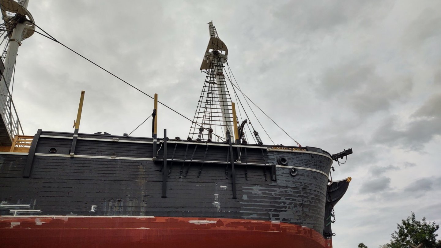
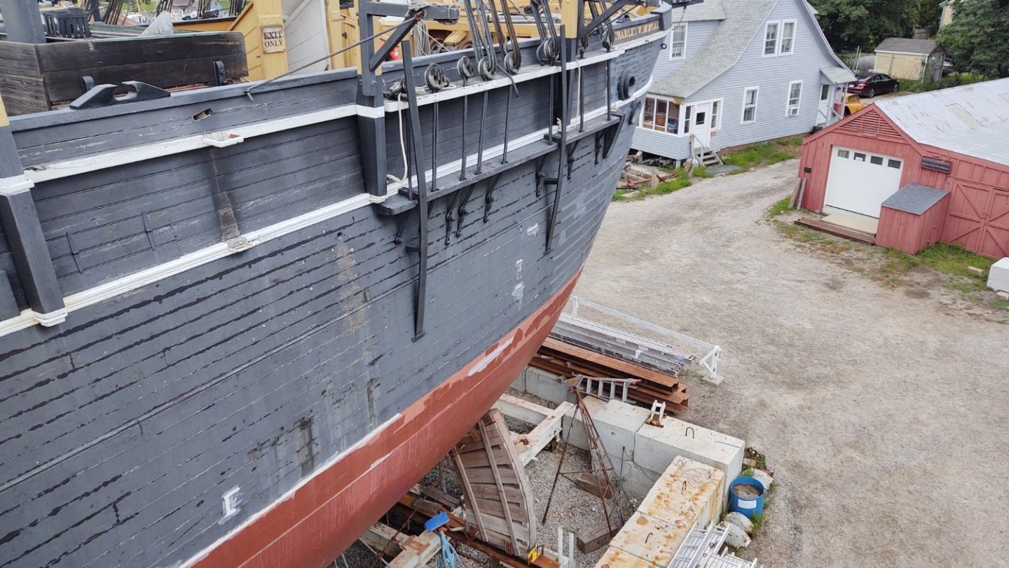
A question for you or ClipperFan (or anyone else) regarding the chain plates. Do you know if McKay clippers used solid iron plates (i.e. an iron bar connected to a separate iron strop (hopefully that's the right word) around the deadeye), or if they were built like the plates in the photo of the Charles W. Morgan below (i.e. a band of iron wrapped around the deadeye that has two segments running in parallel?
Regards,
George K
- BobG and GrandpaPhil
-
2
-
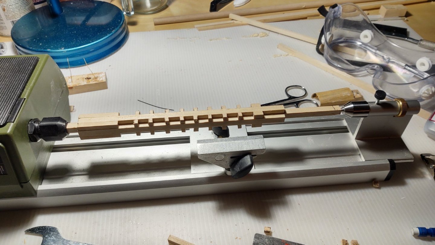
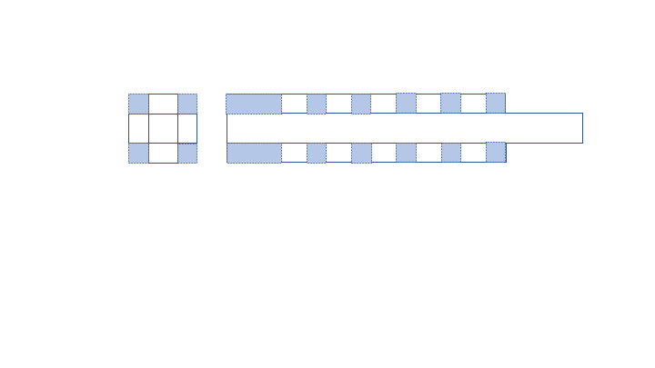
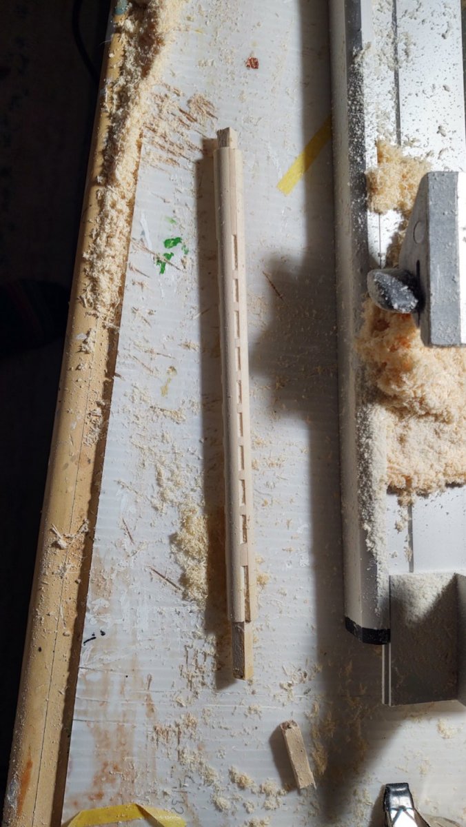
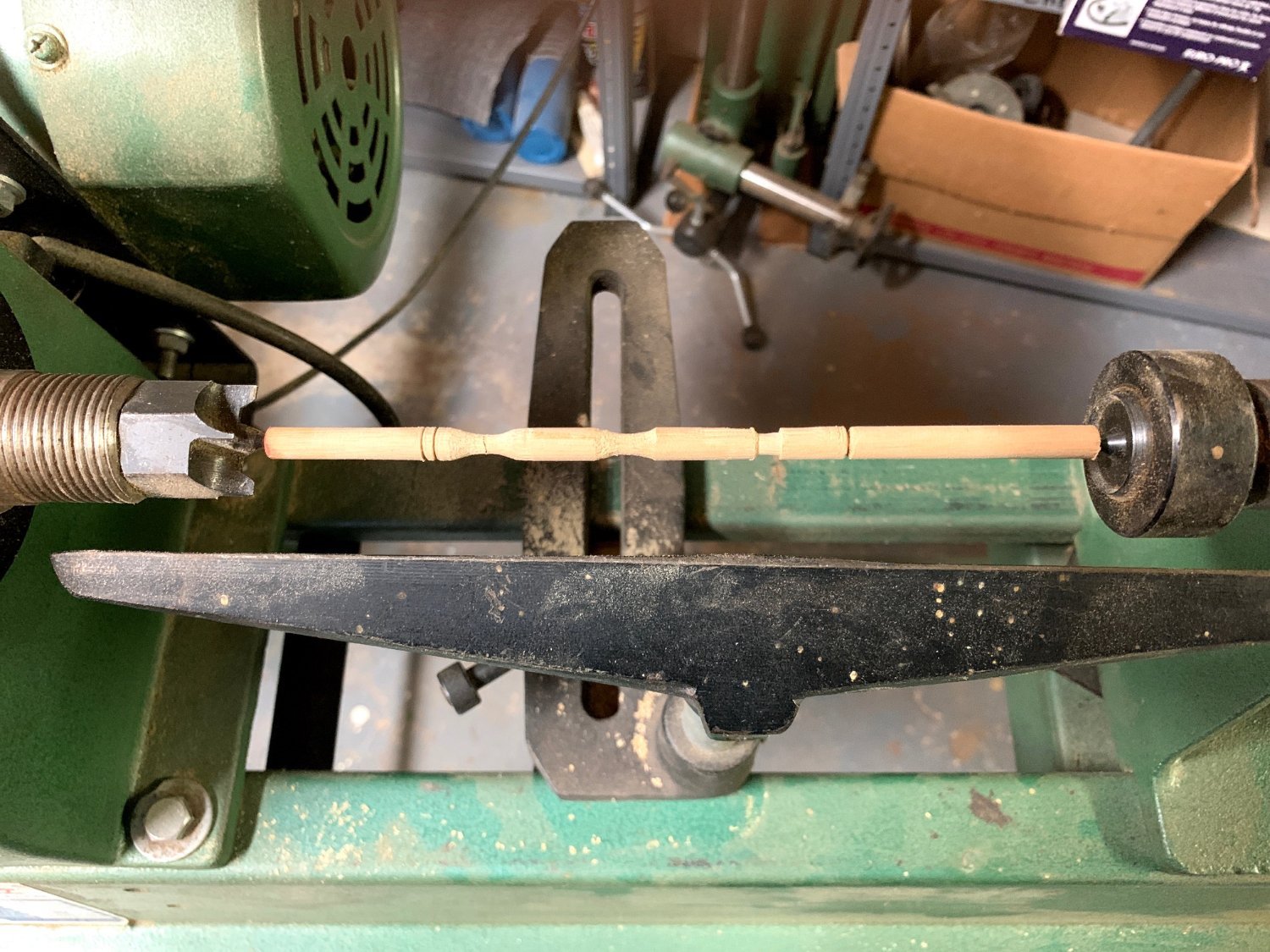
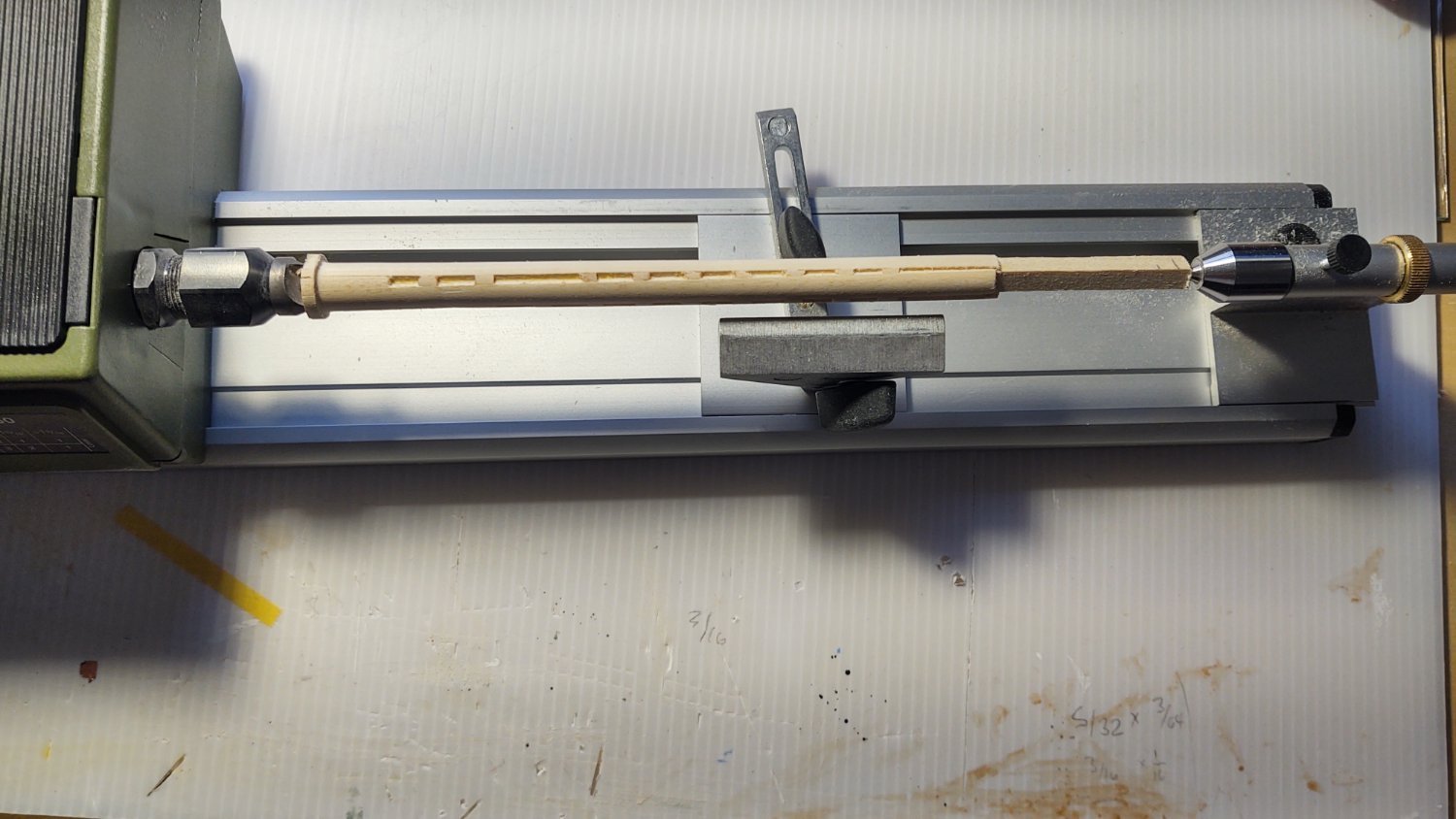
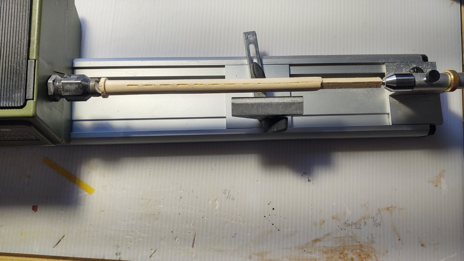
I made a first pass at the built lower mast, in this case, sized for the main mast. It suggests that my method is likely to work, but will require some refinement. I built the mast out of a couple of pieces as shown in the diagram below. The core of the mast is 1/4" square and includes the square portion of the lower mast. It is surrounded by 4 3/16" by 1/4" strips that cover what is going to be round portions of the mast. In the left diagram, which is looking down the long axis, these are the white elements. The built mast has chocks that are placed where the iron hoops are wrapped; these are made with (mostly) 3/16" by 3/16" by 3/16" square blocks and are shown in blue. This is a bit clearer in the right hand diagram which shows the construction viewed from the side.
I put this on my wood lathe. The square is 5/8" wide at the start, and needs to be 7/16" at the base and 3/8 at the transition point to the square part of the mast. As can be seen in the picture below, it generally worked.
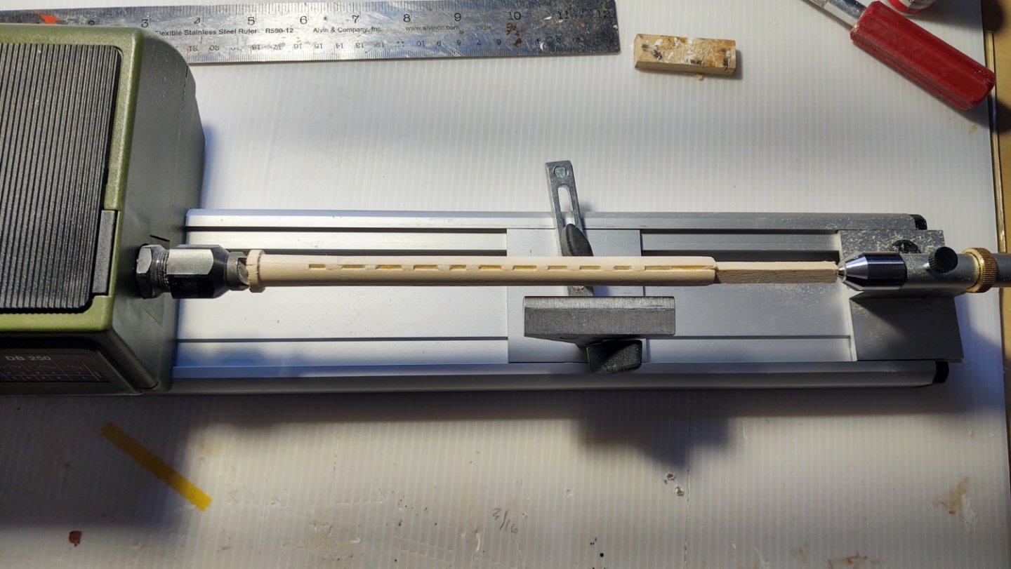
However, as can be seen from the pictures below, my centering was not good enough, so that the other three areas with the gaps were either too large or too small.
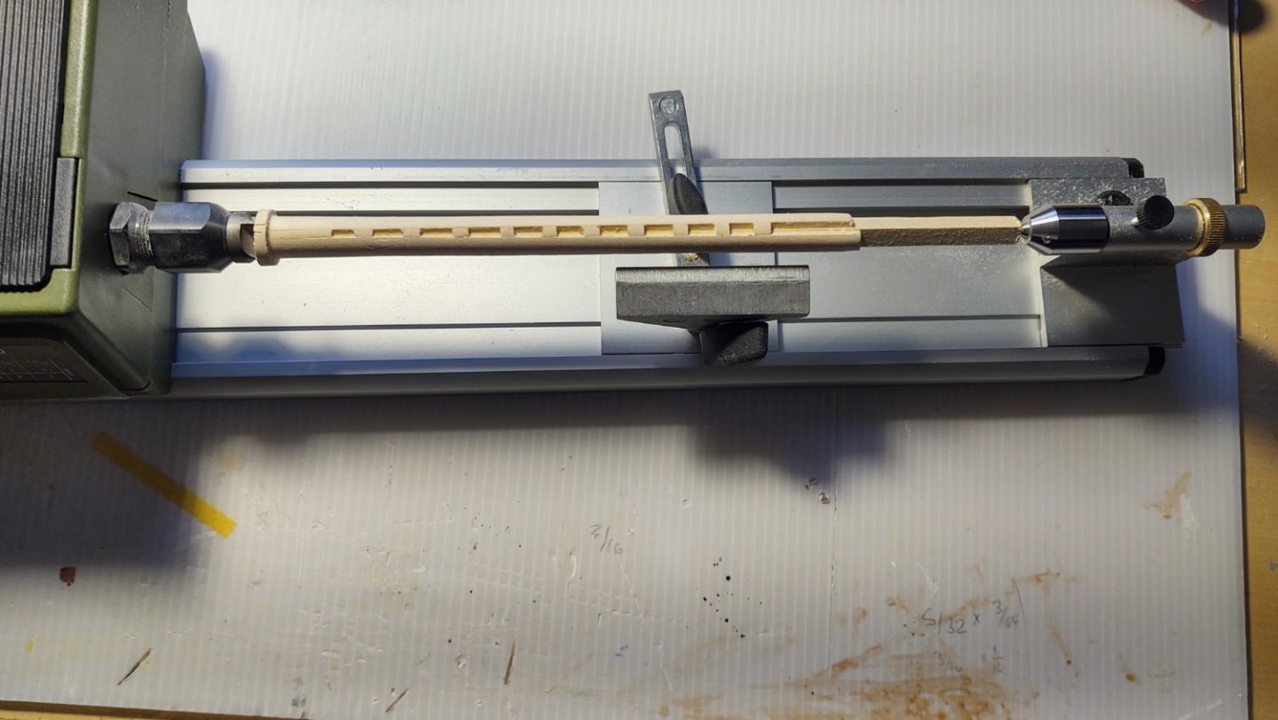

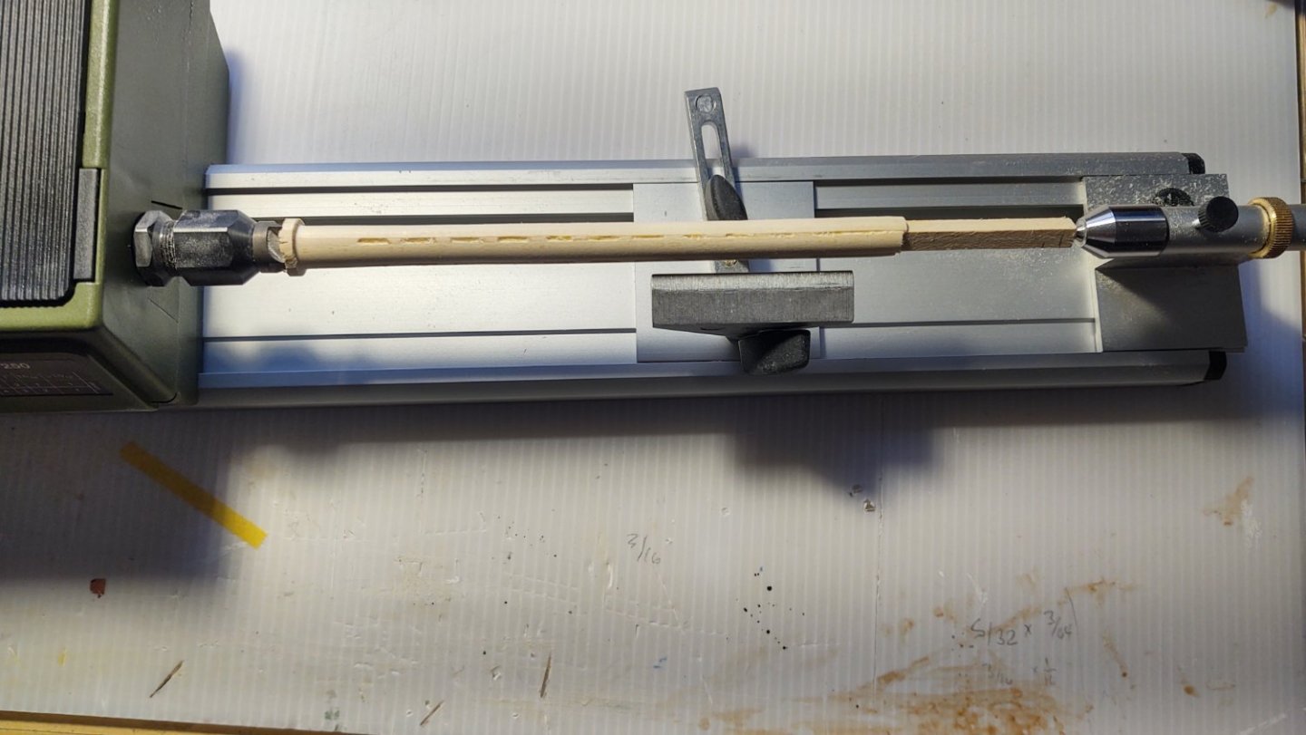
Part of the problem is that I think I centered on the whole structure when I should have defined the center of the square core and not worried about variations in the size of the four 1/4 by 3/16" pieces. I also have determined that it's going to be pretty sensitive to any misalignment between the square and rectangular segments.
Still, for a first try this is encouraging and I suspect that I will be able to make the mast this way.
Thanks again for looking in and for the likes.
Regards,
George K
PS: The plans refer to the mast as being "fished" which is odd. As Rob points out and I recall now, "fishing" a mast is usually a repair technique. So - for this entry and beyond I'll be using the term "built"
- GrandpaPhil, Cirdan, mbp521 and 3 others
-
6
-
9 hours ago, rwiederrich said:
George, you're flying now. She is shaping up nicely and the addition of all the detail makes her snap.
I always build my clippers with some action going on....like an anchor being raised or loosely slung into place, it detracts from a full static display.
Great job. Did you say you are going to make *built* lower masts? Can't wait to see your technique and results.
Rob
Yep. I was planning to use your method, suitably adapted to my tool arrangements.
-
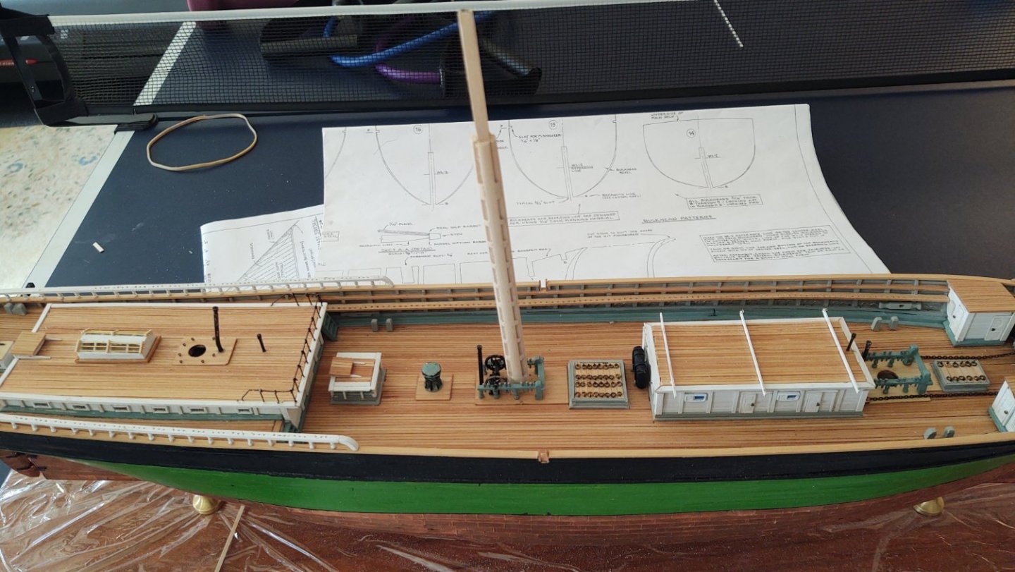
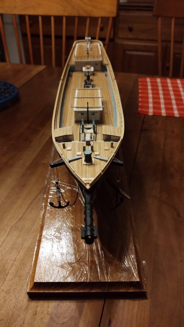
First build update of 2022 (and it is really weird to be typing this. First Blade Runner taking place in 2019, and now we are in the year of Soylent Green - yikes). Anyways, a bunch of mostly small additions that nonetheless consumed way more time than I expected.
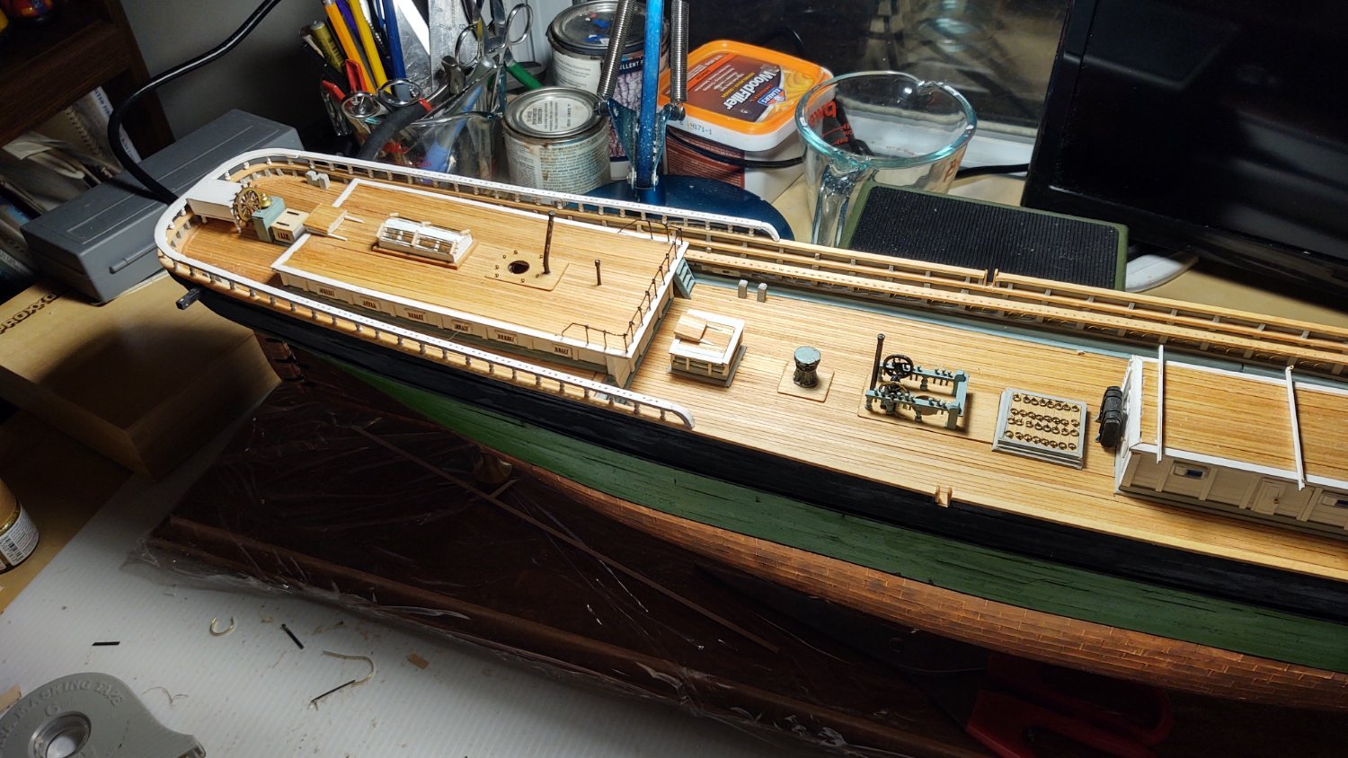
First up, as planned I mounted the starboard pinrail. I then spent the next several days making the carriage house skylight, which consumed a vast amount of time. The skylight is hollow (I built up 4 sides, then put two hollow rectangular frames and a central beam that make up the top of the skylight. I cut sections of clear glass that fit into the frame, and then added pre-painted muntin bars to create the four individual lights. Finally, I set three 24 gauge brass wires to represent the protective bars over the window panes, edged the base in stained decking, and mounted it on the carriage house.
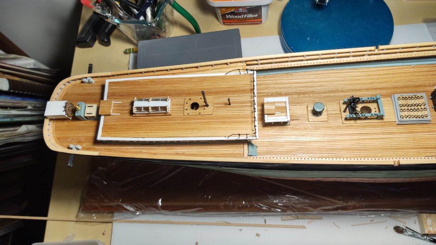
I also made and installed the eight bitts and the four mooring chocks on the main deck. On the forecastle, I added the nails that support the catheads, the spray rail, and the four pads that protect the deck from the anchor flukes when the anchors are stowed. Less visible are the three pinrails on the forecastle, one at the bow, and the other two flush with the deck between the forecastle and the WCs.
.thumb.jpg.ae840989b6daa8451c123c43d6ec3861.jpg)
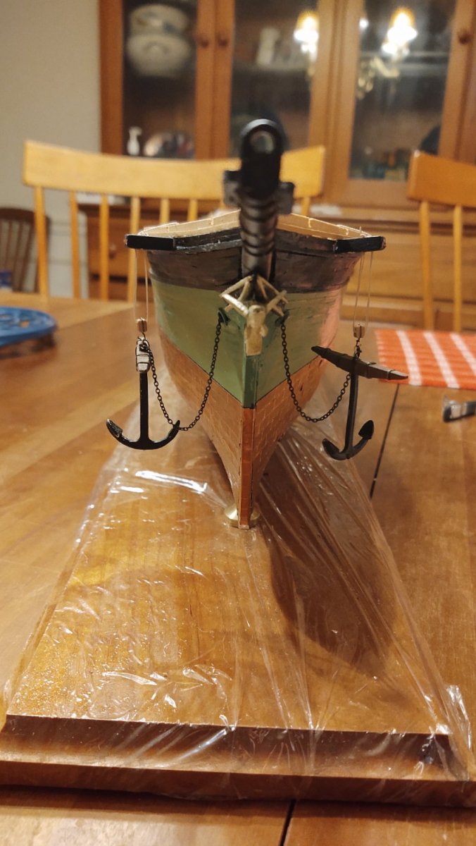
I decided to mount the anchors as if they are being recovered which I think shows them off a little more interestingly than if they were simply lashed to the deck. I connected the anchor chains to the archor using a brass loop, stropped a double block with a hook and rigged the blocks on the catheads.
Seen from the bow, the anchors look thus:
.thumb.jpg.1ad9a8e3922bfc5e4490d1477f42e977.jpg)
The ship as a whole now looks thus:

Pretty soon it will be time to fabricate the taffrail and start on the chains and deadeyes, marking the transition from hull to rigging.
I mentioned before that I was doing some experiments with the ship's boats. Here is the painted boat. The left side has the detail made with Tamiya tape, the right with copper tape. My personal view is that I like the less "in your face" version with the Tamiya tape, and that the Tamiya XF-1 "flat" white is not nearly flat enough. The final version needs to be a lot less glossy. But, I think that with Tamiya taped details, better white paint, and a gunwale painted some contrasting color (likely some brown) the castings will be just fine when turned upside down. The two boats that are right side up will probably also need to have a canvas cover to hide their deficiencies, but I think that will be fine.

As always, thanks for the likes and for looking in.
Soylent Green is People! I mean Happy New Year 2022.
Stay safe out there.
George
-
13 minutes ago, ClipperFan said:
George, Rob Wiederrich has a very detailed explanation as to how he recreated Glory's built masts, including contrasting white painted interiors, varnished wooden exteriors with red iron bands. It sounds odd, but it's really elegant.
Happy 1st day of the New Year 2022!
Yep, I saw Rob's post and am going to do pretty much the same thing, subject to variations in our shop tools and success or failure with said tools. I don't plan on doing red iron bands, but it does work on his Glory of the Seas @rwiederrich


.jpg.1ec28fc6e9924a9cc80ead95651f3176.jpg)

.jpg.7fd59f4d5589329989aa937db2f3ce2d.jpg)
USS Cairo 1862 by MPB521 – FINISHED - Scale 1:48 - American Civil War Ironclad - First Scratch Build
in - Build logs for subjects built 1851 - 1900
Posted
Awesome detail!