


gak1965
-
Posts
608 -
Joined
-
Last visited
Content Type
Profiles
Forums
Gallery
Events
Posts posted by gak1965
-
-
2 hours ago, lmagna said:
While I normally dislike relying on a single author for research and opinion, sometimes there is little or no other opportunity to do otherwise. This may be one of those cases. While everyone touches on the Washington and later London Naval treaties this is the first that I have seen of that focuses on them. I will be adding them to my reading schedule for certain. I hope they are as good as you say.
Thanks
They are very technical but I think they are pretty good. For most of the classes, he has diagrams (mostly side views) and lots of photos.
-
On 6/27/2022 at 9:23 PM, lmagna said:
Not certain if you are referring to the Mogami or the Yamato.
The Mogamis were designed as a result of the limitations imposed by the London treaty which left the Japanese with a relatively small amount of cruiser tonnage and a desire by the Naval staff to nonetheless cram as many weapons onto the platform as possible. They used new welding technologies instead of riveting (in common with lots of navies) to save weight but the first ship (Mogami) was a disaster when it went into sea trials. It was badly overweight, top heavy (and so had stability problems) and the hull was so badly bent during the trials that it affected the ability to train the guns
Eventually, the first two were reconstructed and the third and fourth built to a revised standard based on the reconstructed earlier units. The whole story (and how the Royal, French, Italian, US and Japanese navies designed interwar ships) is told in a set of books written by John Jordan, called (with excellent truth in advertising) "Warships after Washington", and "Warships After London". The books are interesting from the standpoint of how each Navy responded to the challenges of meeting their military needs within the framework of a treaty that put constraints on what they could design and build. Let's just say that the Mogamis weren't the only poor design to come out of the five countries due to the combination of treaty and technological limitations of the day.
George
-
I admire that you are making your own eyebolts and those shackles are amazing. How did you the wood parts in? Was there enough flexibility that you could pop the (former) deadeyes in and have the shackle retain it's shape?
I think your cathead ornaments are great. Anything at 1:96 is going to be challenging, and I had a time making a simple star from copper tape - those are much better!
George
-
2 hours ago, ClipperFan said:
Jared,
Nice way to "bury the lead". Congratulations on your somewhat recent wedding!
Offhand I'd say you were setting your priorities appropriately! Congratulations, indeed! May you have a long and happy marriage!
George K
- Jared and ClipperFan
-
 2
2
-
On 6/21/2022 at 4:59 PM, Ian_Grant said:
Clove hitches were large looking here, and I could not get the two loops to converge together properly on the shroud, so I resorted to half hitches. Not all that happy with the result, see below. The ratlines got tighter with practice as I went up, but on the other hand the left shroud started to hourglass.
Pondering my next move.... 😫
Part.of the problem may be that the shrouds on your test jig aren't under the same amount of tension as the shrouds on the ship, and that tension helps prevent hourglassing. In addition, with my Niagara I clamped two pieces of wood strip on both sides of the shrouds about an inch above where I was working to fight the tendency of the knots to pull the shrouds in.
I wouldn't bother with clove hitches. The scale is so small that almost no matter how good you are, they are going to look too big. At 1:150, a 0.3 mm tall knot (probably the best you can do with 0.1mm thread) is 1.75 inches at scale. I'm with Roger, go with simple overhand knots, secure with some glue or whatever. They won't tug on the shrouds as much and they won't be nearly as bulky.
Looking great!
George
-
-
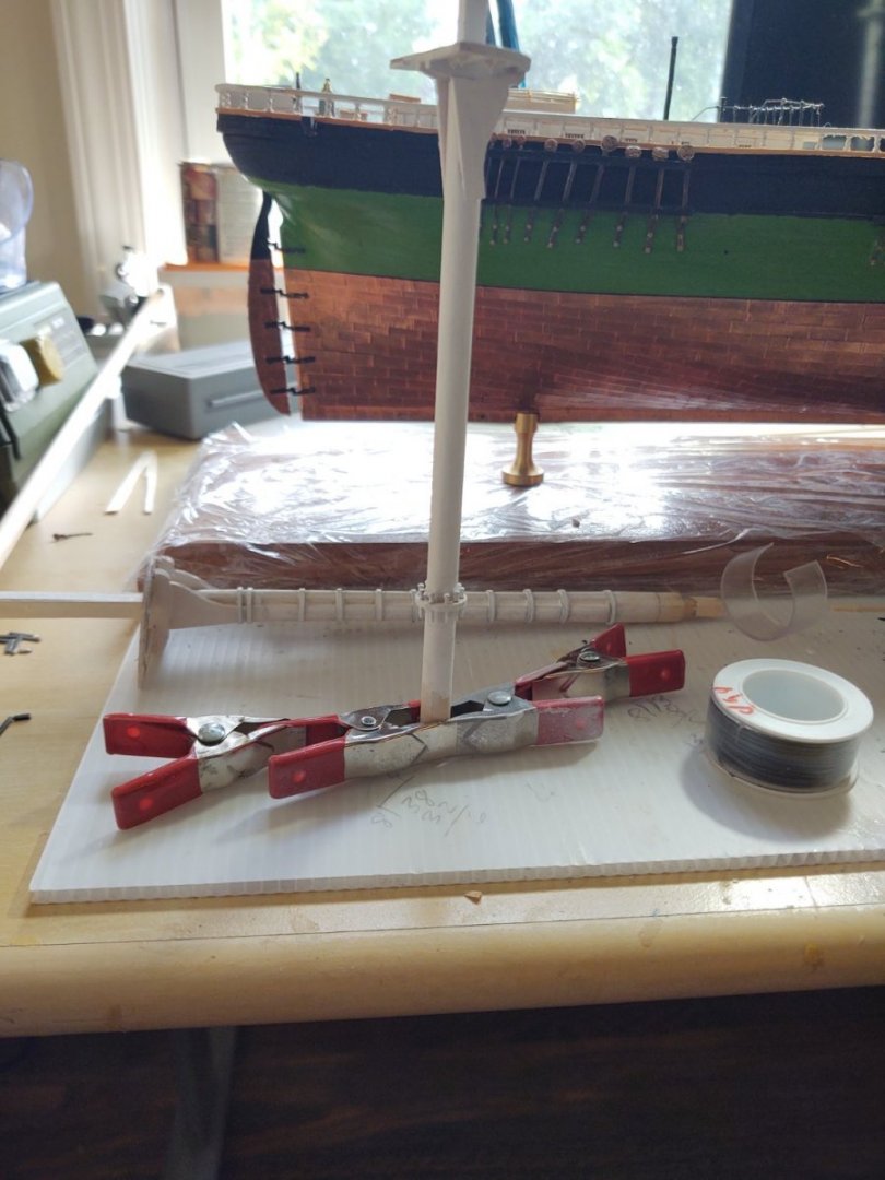
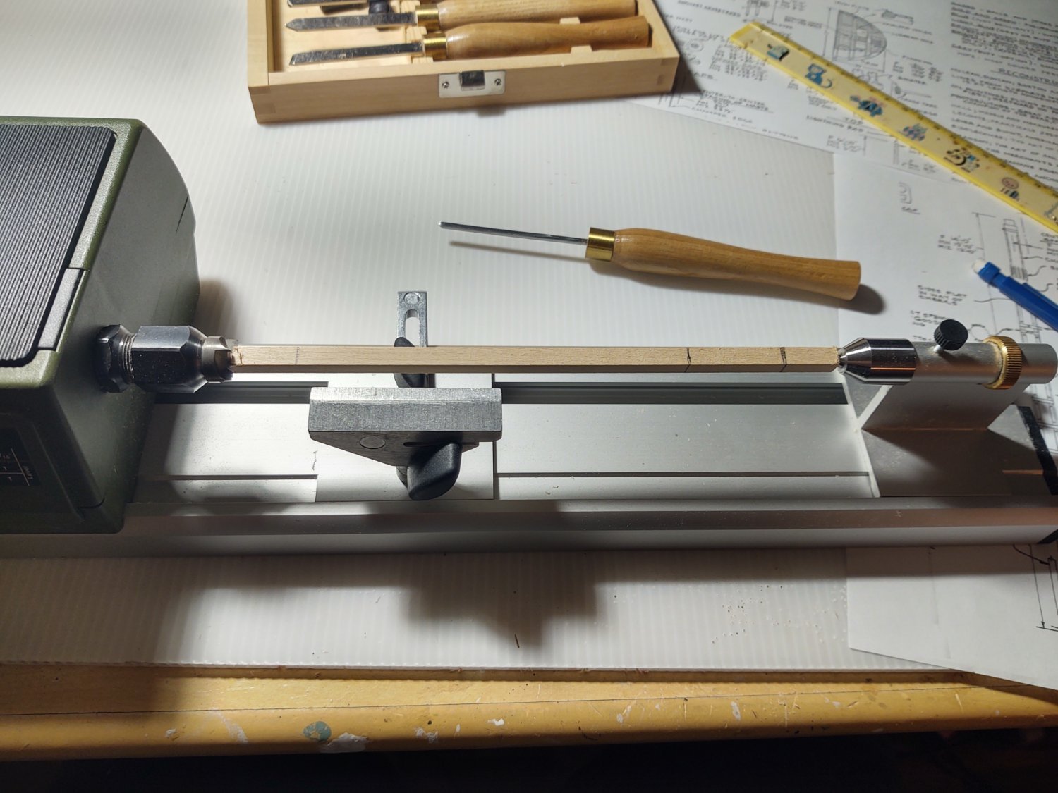
I've started making the topmasts, beginning with the main. Rather than use the kit supplied dowels, I'm starting with larger square stock. For the main that means 3/8 square basswood which I am going to turn and then trim to size. So, the stock on my lathe, marked up to show (left to right) the bottom of square portion of the mast, the end of the round segment, and the end of the square segment. I added a mark (after this picture was taken for the beginning of the round section of the mast.

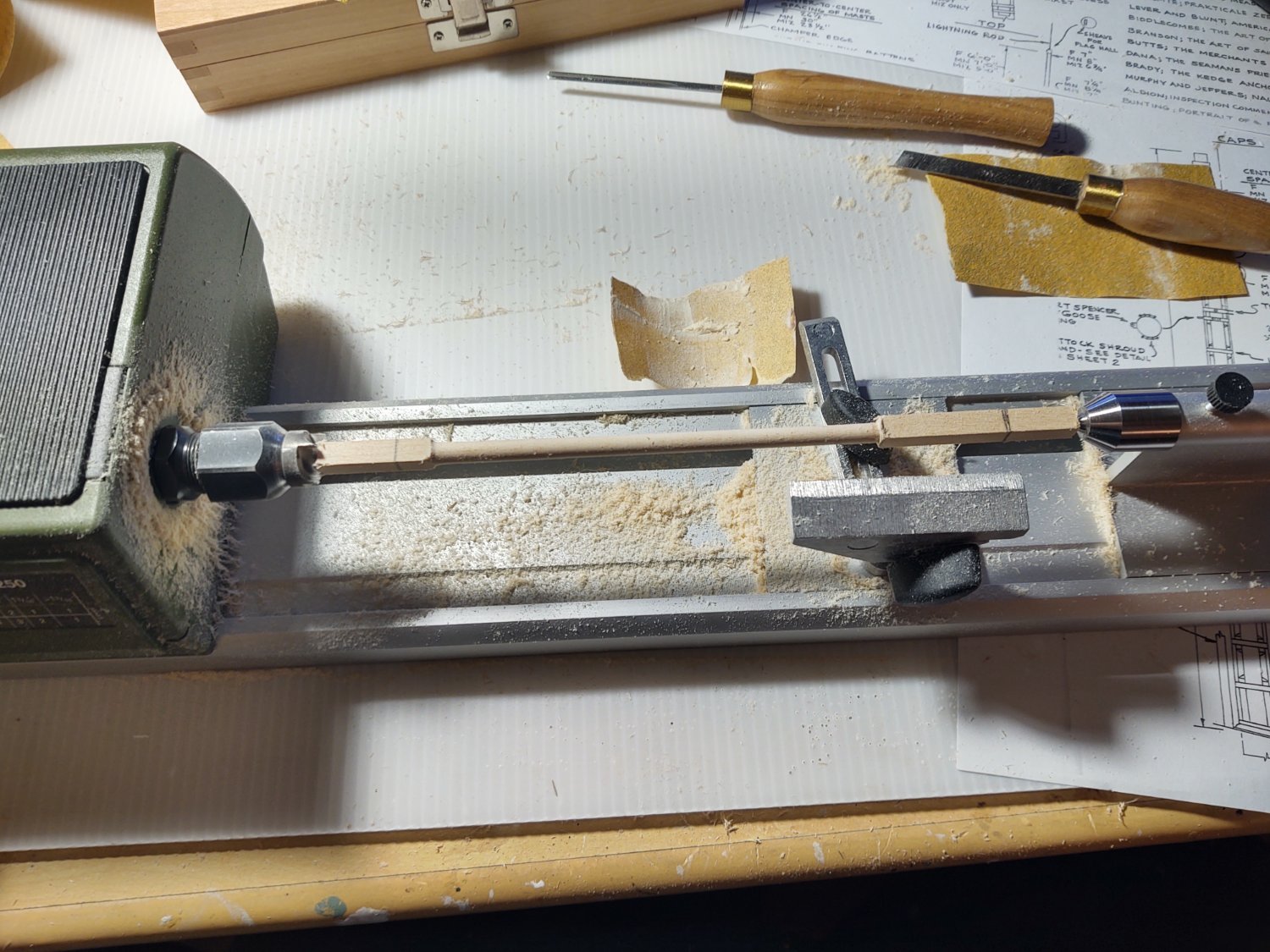
Here is the mast after turning. You will note that the square ends are way too big, as the lower part of the mast should be about 1/4" square and the upper about 3/16" square. This was the expected outcome of this step.

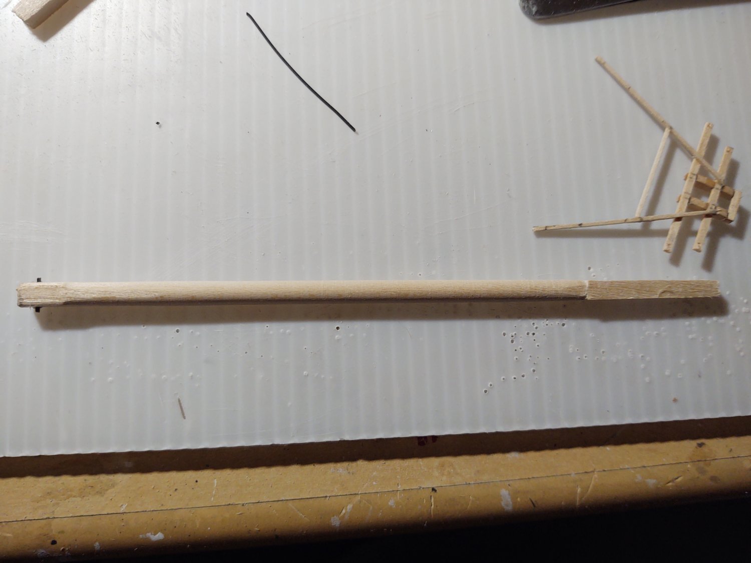
Next I took some 100 grit sandpaper and narrowed the square segments so that they were correctly sized, drilled holes for the fid, and made it from two sections of 1/32 x 1/64" blackened brass. The mast is shown below. Once I'v built all three, I'm going to stain it so that it is a little darker.

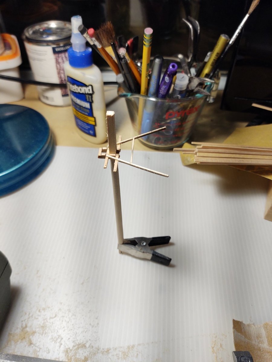
Next the trestletrees, crosstrees, and spreaders. These were made out of boxwood stock. In order to get the the crosstrees to be properly aligned on the trestletrees, I dremeled the cutouts with a cutting blade while the two trestletrees were clamped together. The crosstrees themselves are made from 1/16" x 1/32" stock, and quite flimsy before they were mounted. The spreaders are only 3" square in real life (1/32" at scale), and I was very worried about the loads that they were going to be under. So, I took some blackened 1/64" x 1/32" brass and glued it to the bottom of spreaders. You can see the this in the next two photos of the trees and spreaders from above and below (the marks are where I need to put the cleats and will be removed).
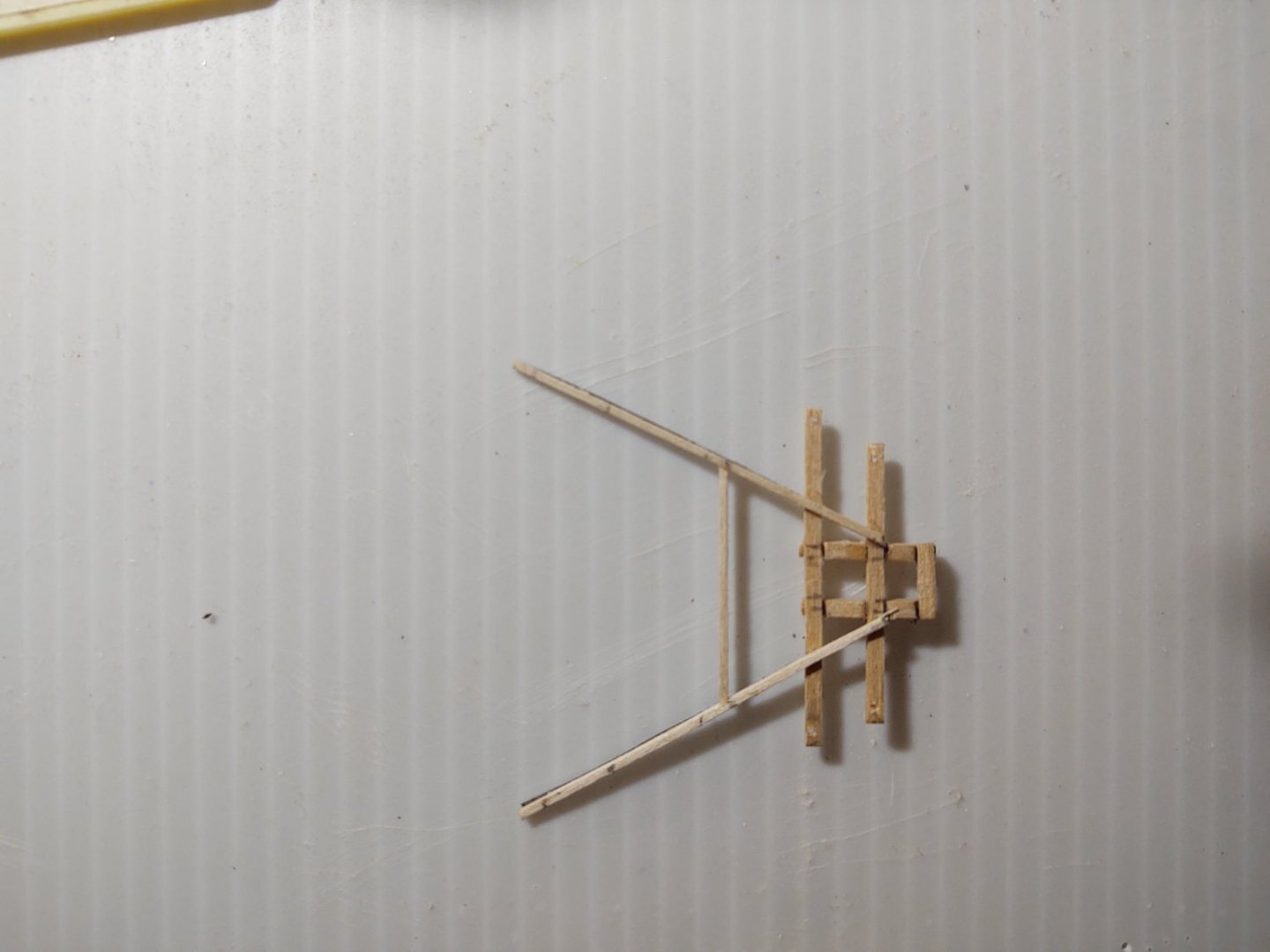
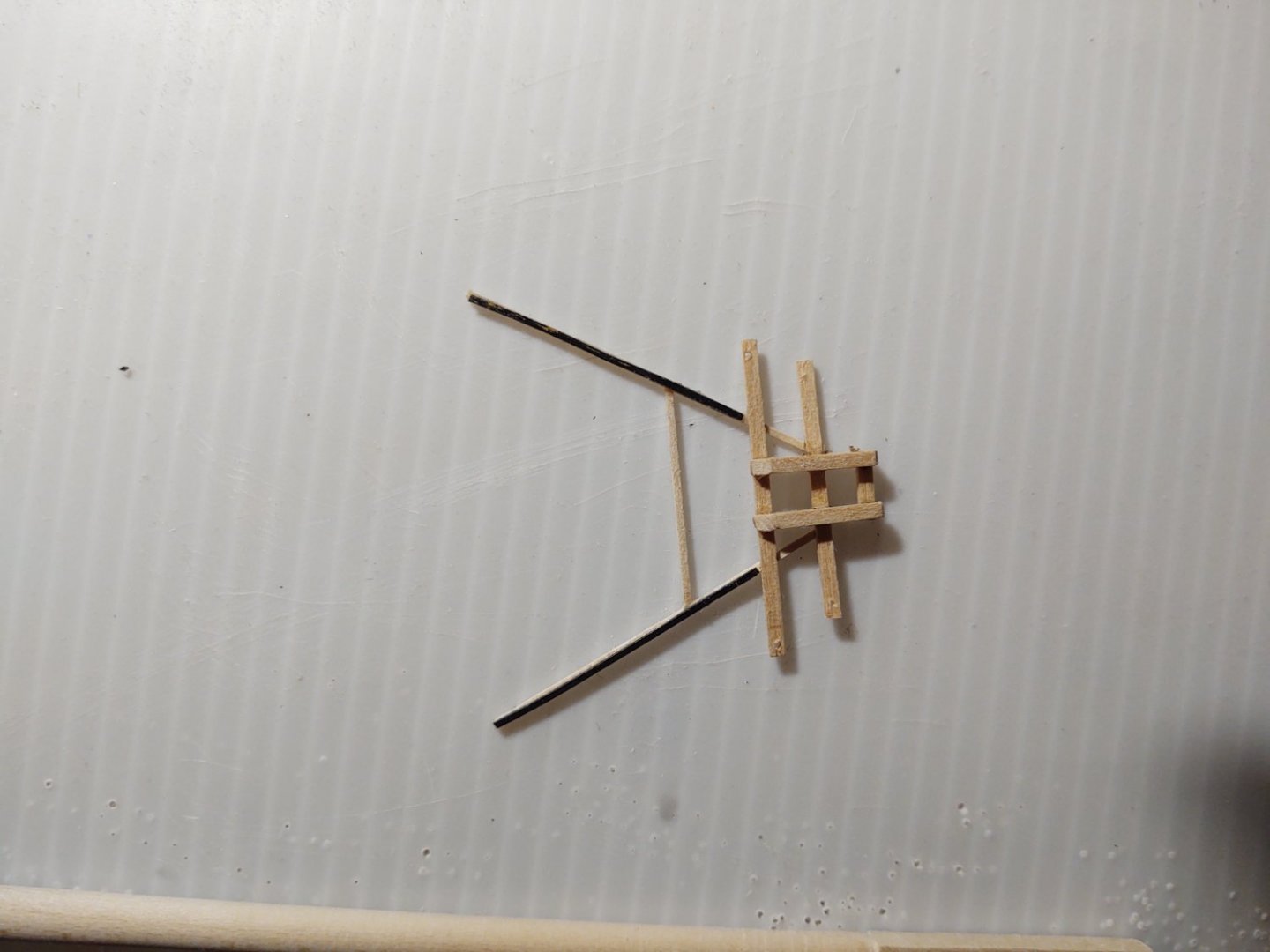
The brass is barely visible, and I may put some on the brace as well. As with the mast, once all three are made I'm going to remove all the pencil marks and stain them. I haven't decided yet if I am going to make the six cleats out of wood (they would be really small and fragile) or put an opened jackstay eyebolt or perhaps a bit of very fine wire. They are going to be sufficiently hidden by rigging that I'm inclined to simplicity.
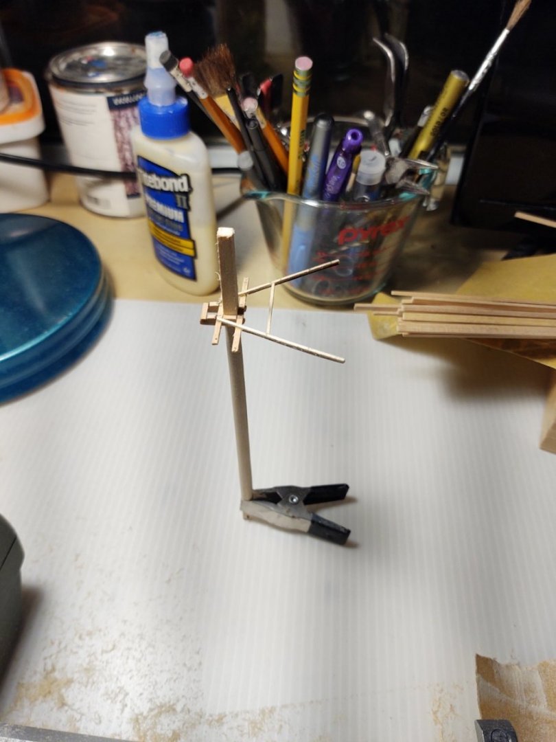
I wanted to get an idea what the whole assembly will look like on the model, so I slipped them onto the mast, and I have to say I am reasonably pleased.
Thanks again for looking in!
Regards,
George K.
- Cathead, robdurant, GrandpaPhil and 5 others
-
8
-
Looking great! Rigging ho!
- Ian_Grant, Keith Black and robdurant
-
3
-
When I was a boy, my grandfather built the 1:200 Nichimo version with the lights, working props, etc. I don't know what happened to it ( it got lost sometime in the intervening 52 years) but I've scanned ebay more than once for one of them. May need to make the investment, although goodness knows where I'd display it. at least it wouldn't be as tall as the sailboats so, lower case height.
-
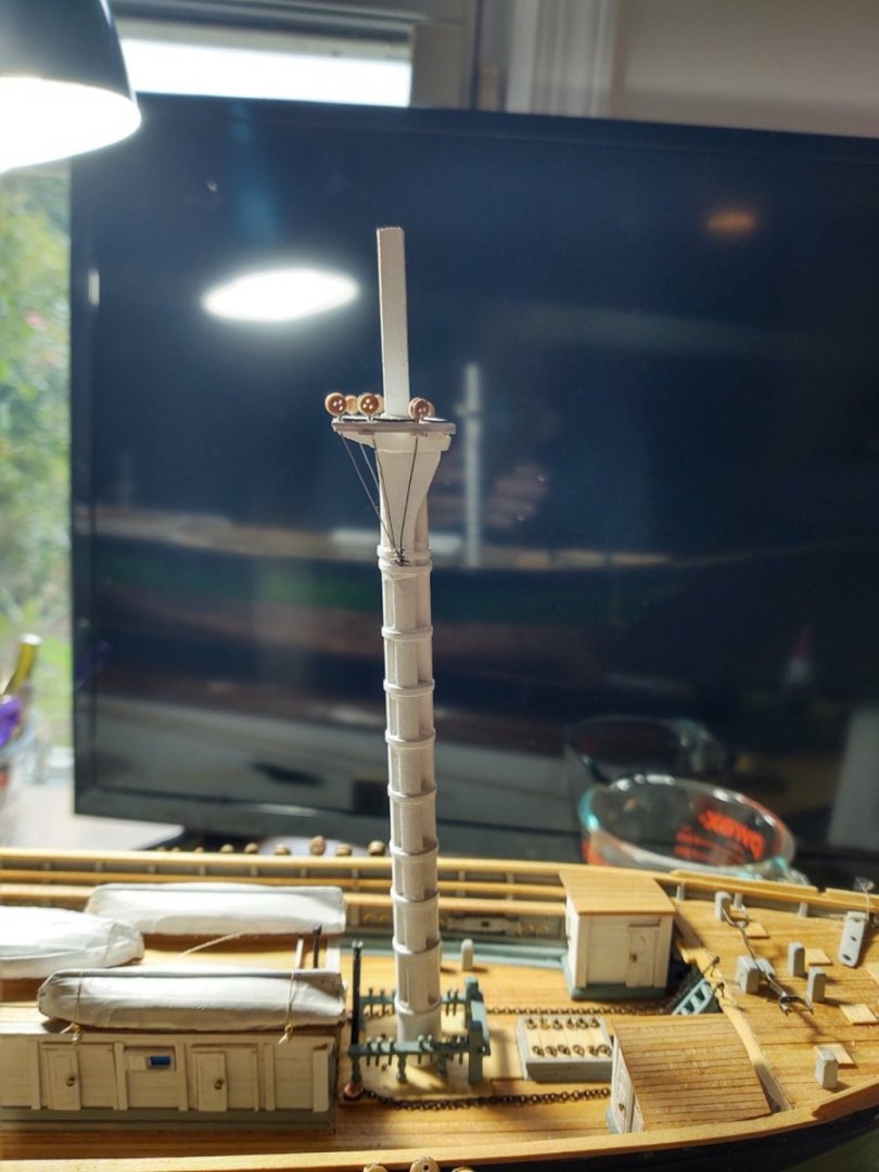
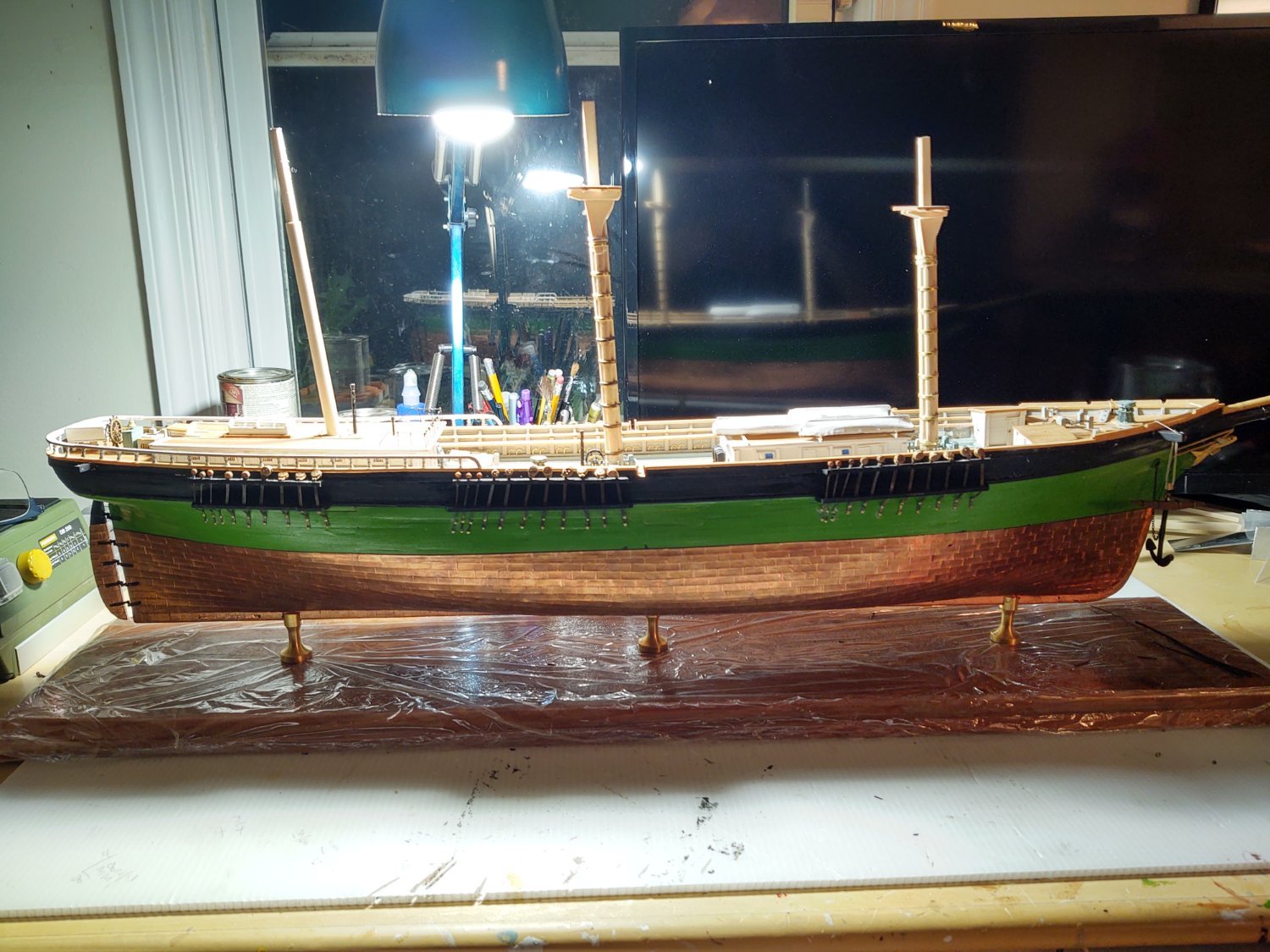
Well, an update. I've been working on the lower masts while I finish odds and ends on the deck. Lots of photos for me (well 6) but we are in a period where many things get done but the ship doesn't change much in overall appearance. With additional paint, the main was painted, and it is time to start adding additional details, including the iron reinforcing on the tops and the holes for the fairleads.
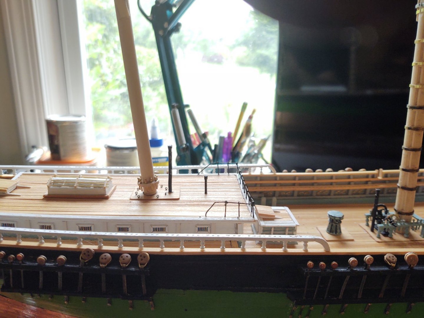
The first new thing that needed doing was the spencer jackstays on the fore and main masts. They are theoretically 1" or 0.01" at scale. I built mine from 24 gauge black steel wire and 0.75 x 6 mm brass eyebolts that were chemically blackened. That would make them about 2x scale, but it isn't terribly noticeable. The jackstays on the yards were smaller and I will likely use a finer wire when I make them. Here is the foremast with the spencer jackstay.
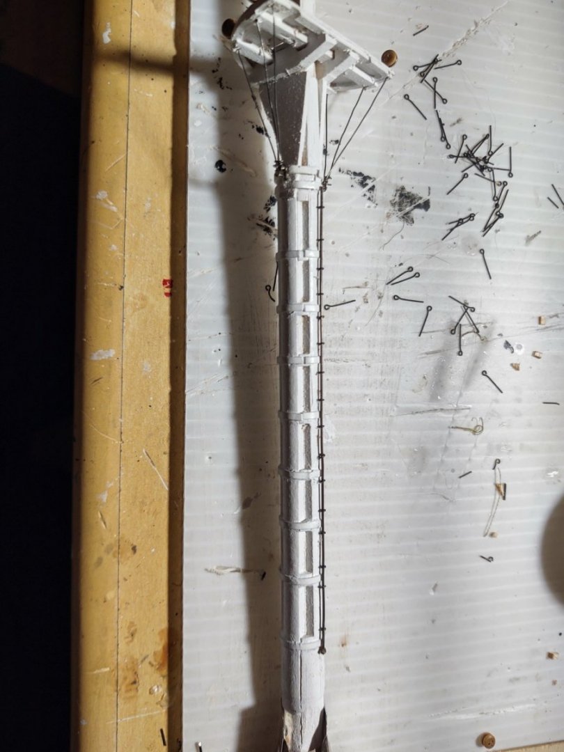
Next I made the futtock shrouds from deadeyes and some fine gauge black wire. The ends were threaded through the pre-drilled holes in the top and attached to a large eyebolt that is filling in for the individual mounting points on the relevant iron. Finally I drilled a hole in the masts for the gaffs and mounted a piece of 24 gauge wire that will eventually become the gooseneck. I have seen people use circles cut from blackened copper tape to make fairly convincing hinges at this scale and that is the plan for these gaffs. Here are photos of the fore and main masts with the jackstays and the futtock shrouds.


This picture also shows that I installed the amidships ladders. I ultimately used the castings, they seemed as good as I was likely to make on my own, and (on the fore) that I've started installing the blocks for the bunt and clew lines. Ideally the blocks would be of four sized (two different sizes on the main/fore) and a second (smaller) set of two sizes on the mizzen. The kit comes with three sizes of single block and functionally all 4 block sizes were closest to the 3/32 inch size - so all 24 will be the same size.
The mizzen required a spencer mast, which I built from a dowel and a some strip brass bent to accept a 24 gauge wire that will be the gooseneck, the spencer and then wraps around the lower mast. I also added the futtock shrouds, and here is a photo:
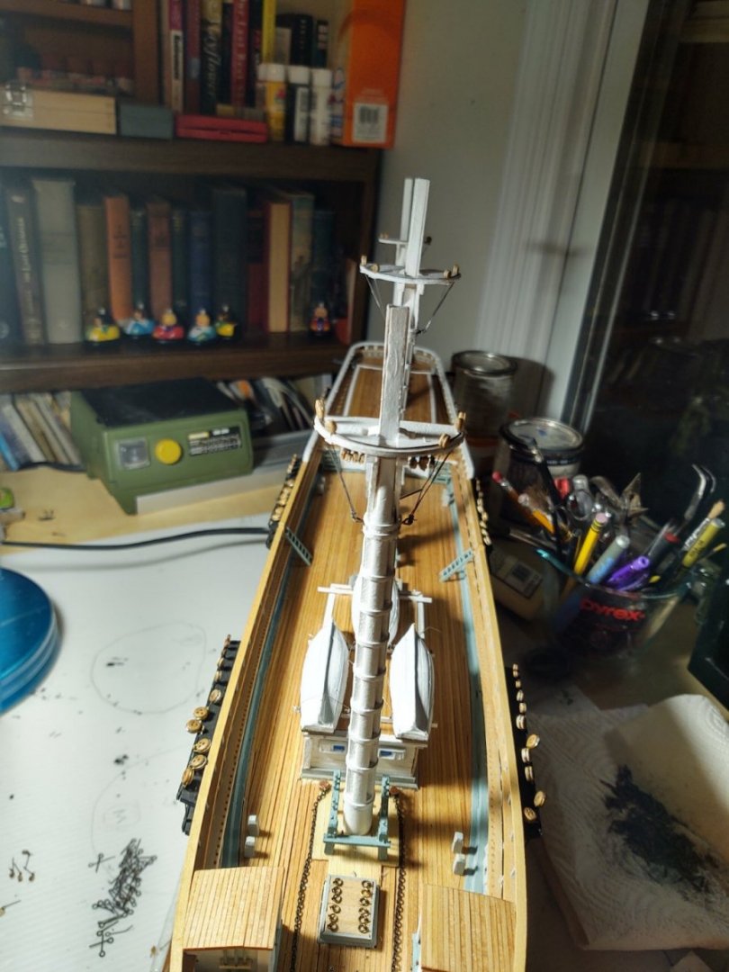
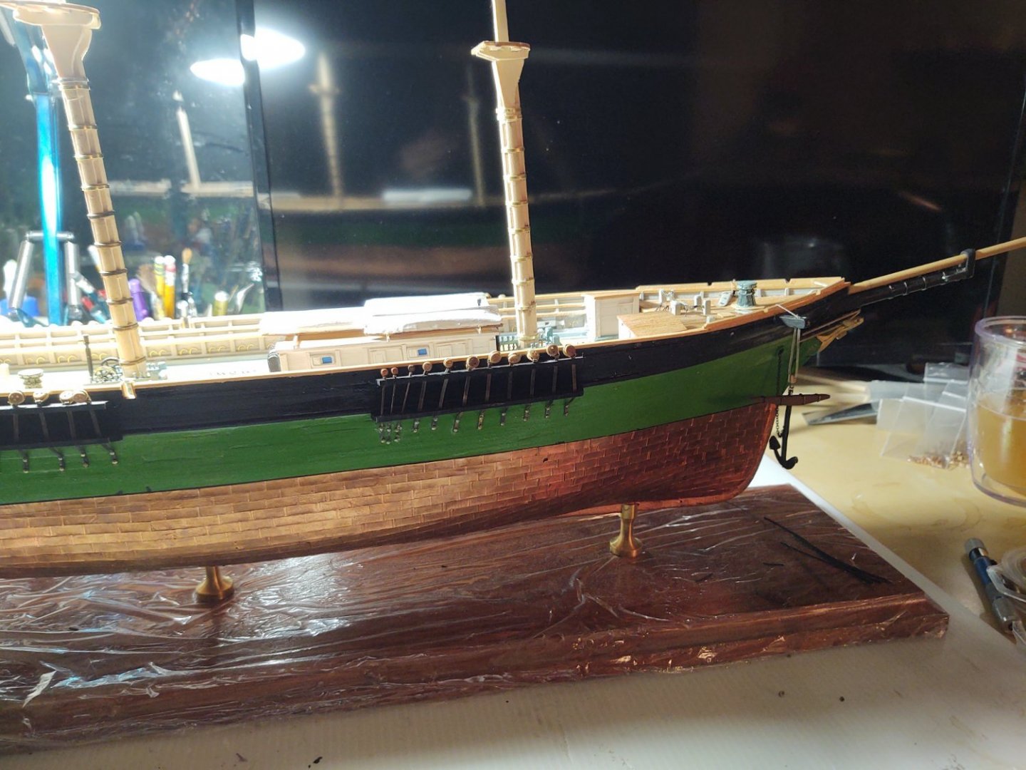
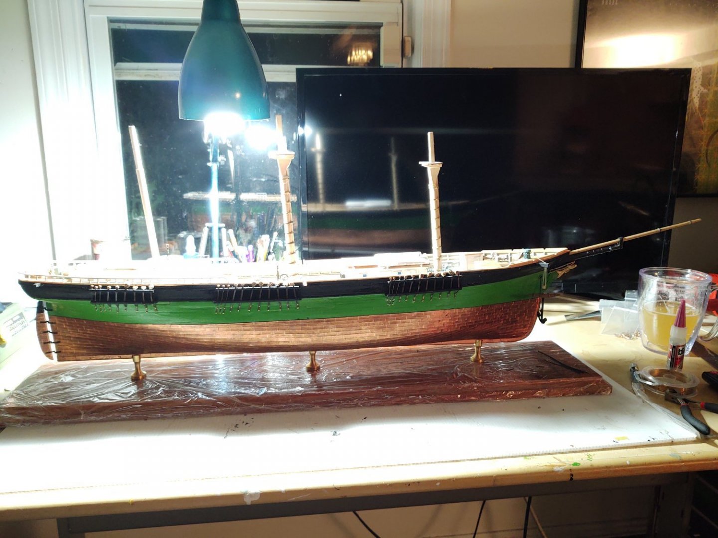
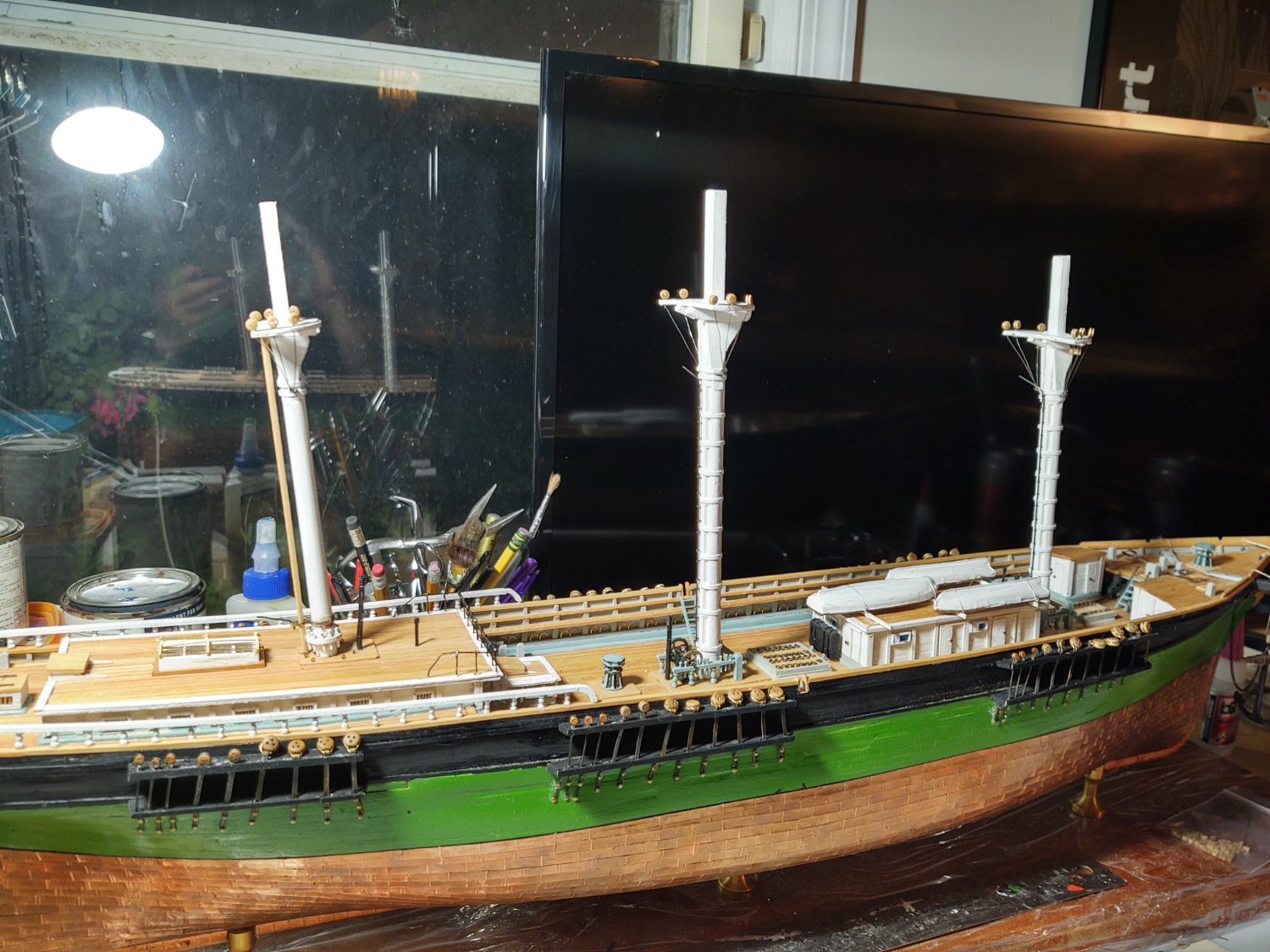
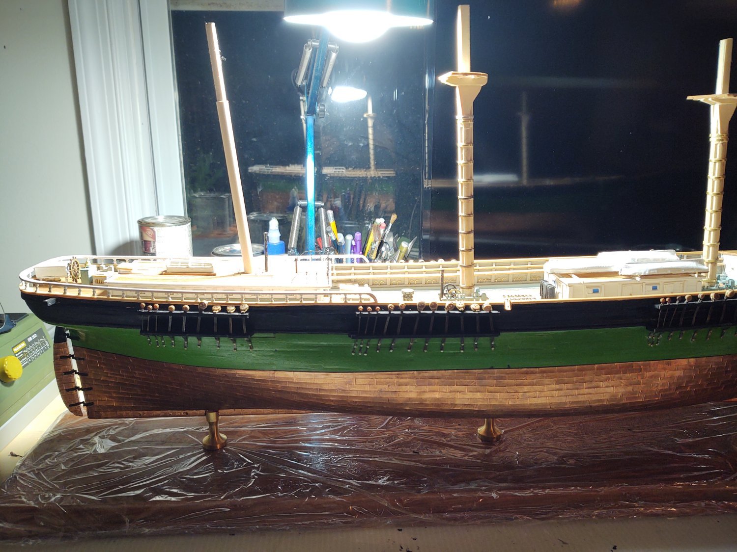
So, the ship looks like this now with all of the masts in place (but not yet glued in). The mizzen is slightly more raked than I want, but the picture makes it look worse than it is. I am going to get in there with my Dremel so that it will stand at the same rake as the fore and main.

Finally, a view of the ship from the bow showing the masts which. Again, the alignment appears a little off because they have no shrouds and are not glued in place.
Next up - on the right of the final photo you can see the brass belaying pins that I hit with some patina. I think I need to give them another treatment to make them more uniform, but otherwise they are ready to be placed. Finish stropping the rest of the blocks that are mounted on the tops (16 down, 8 to go) as well as a couple of blocks for the mizzen braces that mount on the top, and then it's time to make the topgallant masts. I build (but don't rig) the entire mast before doing it's final mounting and starting to put the shrouds in place. Hopefully that time will start to come soon. In the interim I will probably start to rig the boswsprit to give me another area to make some obvious progress.
As always, thanks for looking in and the encouragement.
Regards,
George K
- GrandpaPhil, Bruma, ccoyle and 5 others
-
8
-
I wound up chickening out on my Passat. 1 fewer mast but at 10/inch, what a mess. And the Heller Ratline maker was a joke.
One thing to check, the current Passat only has ratlines on 3 of the shrouds per mast, did Preussen use them all or did they only use the inner ones? I don't think people went aloft as much on the newer windjammers as compared to say a 19th Century warship
-
Saw this yesterday, thought people might be interested. It's a 1 minute clip of HMS St. Vincent (1815) making sail one last time before going to the ship breakers in 1906. No sound, but one of the few moving images of a Napoleonic era 1st rate. https://mobile.twitter.com/simonharley/status/1534068550935236609
-
5 hours ago, ClipperFan said:
To get an idea of this built in ruggedness, take a look at the relative open, near frailness of the Tea Clipper Cutty Sark.
I think we can agree that McKay was a great naval architect without beating up on the Cutty Sark. The two ships were designed for different purposes (tea trade vs. going around Cape Horn) and Linton designed around composite construction rather than all wood.
It would frankly have been interesting to see what McKay would have done with composite construction (and steam) had the yard survived. The Essex that he built in 1874-1876 (although I don't know if he designed it) wasn't stricken from the Navy rolls until 1930(!)
George K
-
2 minutes ago, gak1965 said:
My assumption has always been that you use built masts when getting solid masts of the correct diameter is too expensive. As @ClipperFan points out, the mizzen is narrower than the bowsprit. I'm going to guess and say that McKay could get 2 feet diameter solid masts but 3.5 feet was becoming prohibitively expensive due to more than 2 centuries of logging around Boston. The photo of Glory in Alaska (where finding big trees would be less of an issue) with a fished main, and solid fore and mizzen would seem to bear this idea out. Given that, and the fact that the description of the fore and main (but not the mizzen) mentions fishing, I think I'm going to go with a solid mizzen.
The iron hoops are more open to question. In a straight pole, I would think that the hoops would be useful in preventing the mast from failing due to forces acting along the axis of the mast (i.e. downward forces that would tend to split the wood fibers apart) and not forces that are applied parallel to axis of the mast (i.e. forces from the winds on the sails). If there are proper engineers out there, please correct me.
Both paintings have value to get the proper look of the ship, but both have issues. Butterworth, for example, removed all of the deadeyes from the shrouds and backstays, the China Trade painting doesn't have the masts that are known to be fished, but has hoops. Actually, calling them issues is a bit harsh, in both cases, I'm guessing they worked.quickly and/or from sketches because they didn't have photos available, and so inaccuracies crept in. But they are both models in a sense, artistic representations of more complex real things.
Ideally, an engineer tells me if my supposition about the utility of the hoops is right or wrong. Barring such information, I think I'm going to go with solid mizzen, no hoops given that the photos of Glory's masts don't show them when they are poles and not built.
it's fun, kind of like a detective story to go with the construction.
Warm regards,
George K
On the other hand, because the mizzen has a Spencer mast there would be no problems with catching the hoops when raising the spanker.
-
3 hours ago, Rick310 said:
The model of the flying cloud at the Boston Museum of Art does not show fish on the mizzenmast although the fish on the main and foremast are very difficult to see so I could be mistaken.
Does anyone out there have any ideas?
My assumption has always been that you use built masts when getting solid masts of the correct diameter is too expensive. As @ClipperFan points out, the mizzen is narrower than the bowsprit. I'm going to guess and say that McKay could get 2 feet diameter solid masts but 3.5 feet was becoming prohibitively expensive due to more than 2 centuries of logging around Boston. The photo of Glory in Alaska (where finding big trees would be less of an issue) with a fished main, and solid fore and mizzen would seem to bear this idea out. Given that, and the fact that the description of the fore and main (but not the mizzen) mentions fishing, I think I'm going to go with a solid mizzen.
The iron hoops are more open to question. In a straight pole, I would think that the hoops would be useful in preventing the mast from failing due to forces acting along the axis of the mast (i.e. downward forces that would tend to split the wood fibers apart) and not forces that are applied parallel to axis of the mast (i.e. forces from the winds on the sails). If there are proper engineers out there, please correct me.
Both paintings have value to get the proper look of the ship, but both have issues. Butterworth, for example, removed all of the deadeyes from the shrouds and backstays, the China Trade painting doesn't have the masts that are known to be fished, but has hoops. Actually, calling them issues is a bit harsh, in both cases, I'm guessing they worked.quickly and/or from sketches because they didn't have photos available, and so inaccuracies crept in. But they are both models in a sense, artistic representations of more complex real things.
Ideally, an engineer tells me if my supposition about the utility of the hoops is right or wrong. Barring such information, I think I'm going to go with solid mizzen, no hoops given that the photos of Glory's masts don't show them when they are poles and not built.
it's fun, kind of like a detective story to go with the construction.
Warm regards,
George K
-
26 minutes ago, ClipperFan said:
George, from the many images of Glory I've seen, it appears like these are her original tops. Here's another scene of her in dry dock from a lower starboard bow view. The lubbers holes are more visible in this one.
Finally, I've included a rare stern scene of Glory docked in Alaska. The large rear coach house actually curves gracefully to accomodate dual catwalks which surround both sides. I estimated they're 5' wide and stay consistent from front to rear of the house. Since your foundation appears to be the sole part of your particular coach house, I felt you might appreciate knowing the actual configuration of this section of McKay's vessels.
Thanks for the info.
My carriage house also curves toward the stern although I don't think it leaves perfect catwalks. Whether it is too narrow forward or too wide aft, I don't know. I think it's about 5 ft forward and 3.5 to 4 ft aft. The Fish is smaller than Glory and might have been tighter as a result.
I'll see how much I can file away on the tops without endangering the fairleads. 1:96 ca be unforgiving at times.
George K
26 minutes ago, ClipperFan said: -
The description of the Fish's masts (which I know you've seen) says that "Her fore and main masts are fished on every square, and closely hooped, and the fishes extend two feet below the lower deck partners. No ship belonging to this port has such massive lower masts." There is no mention of
the mizzen, which I presume is why Ben Lankford ultimately went with a stick mast.
The Butterworth painting does show a fished mast, and the China trade painting shows sticks with hoops on all three masts. Would it have been common to put hoops on a stick mast? I don't recall seeing them on the Pacific photos of Glory when it had switched from but to stick masts.
It is probably possible to open up the lubber's hole a bit before I seat the mast. The holes were defined by laser cut pieces and are between 1.5 and 2 feet on the short side at scale which are narrow, but I don't have very good reads on the actual size of such a hole. Do you know if the tops in the photo are the original ones or added later?
-
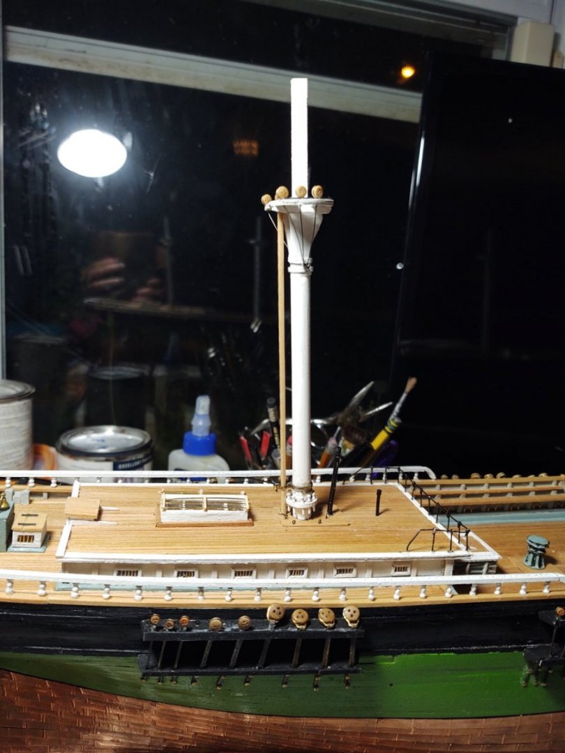
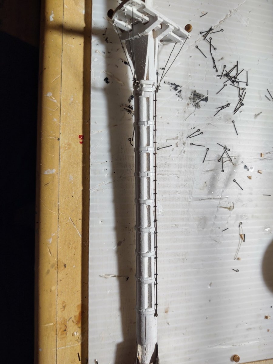
Well, some progress on the lower masts. The fore and main were mostly constructed, but not painted or any additional details added. The mizzen needed the ring of belaying pins, which is the next item I worked on. I marked out the relevant circles on a piece of appropriate thickness wood from the kit, drilled a pilot hole and then used a conical grinding bit in my dremel to make the hole. I then drilled out the holes for the pins, and finished the outside with a sanding bit. It was the only way I thought I could make it without having the whole thing break into a million pieces when I drilled the holes for the belaying pins. As it was, it split in two, but a little glue and we were back in business, as seen below:
Next up was to paint the lower masts. I started with some Tamiya flat white from a spray can to get a base on the pieces, followed by brushing on Tamiya flat white to get good coverage. Unfortunately, I ran out of paint, so I've only done the fore and mizzen. The photo below shows the mizzen and the main, and you can see the difference between the spray only and the final look (the unpainted portion of the mizzen will be out of sight).
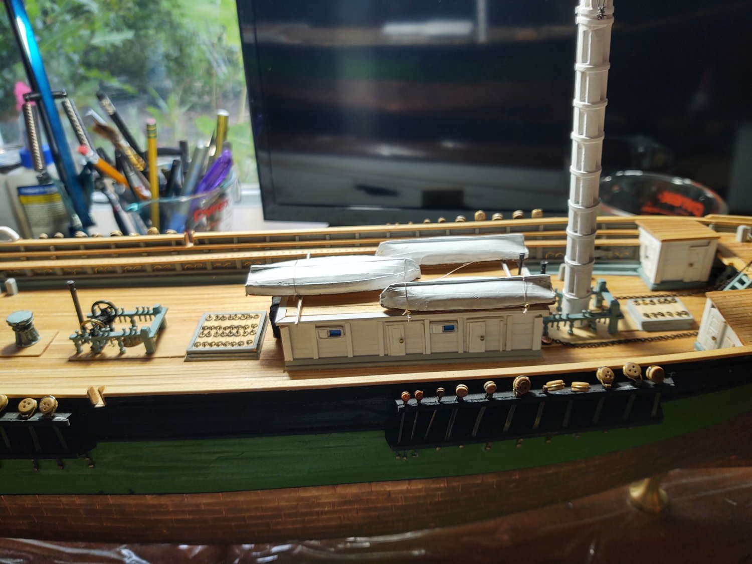
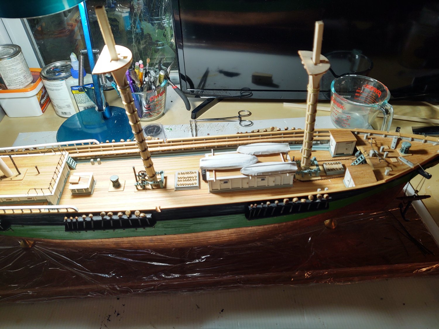
Oh, while i was waiting for paint to dry I mounted the ships boats on the main deck house (the mast is not yet attached, and it's an optical illusion that it is facing forward).

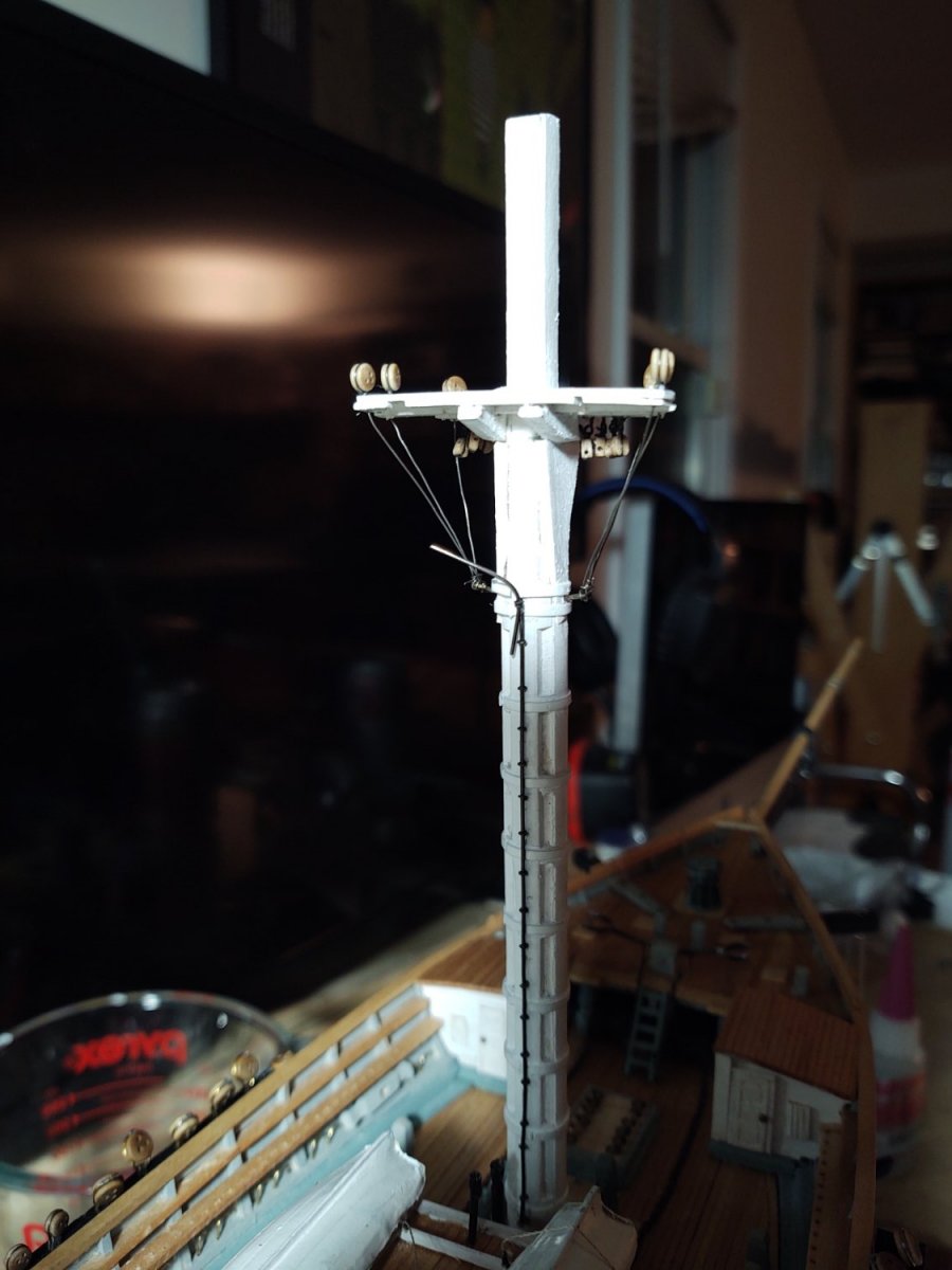
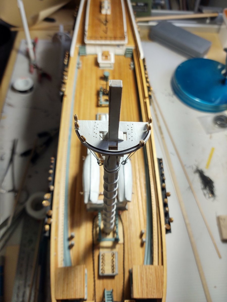
I then spent some time on the foretop. After painting, the holes for the futtock shrouds and fairleads had to be reopened. In addition, the plans indicate that the tops had an iron band around the curved edge. I made this with some black, 24 gauge steel wire, bent to shape on the edge of the top, and leaving the holes for the futtock shrouds uncovered (so basically there were 5 pieces of wire, each between one of the 6 holes). The futtock shrouds were made from 1/8 deadeyes (the closest I had to 10" at scale) and black 32 gauge wire, anchored onto the futtock band using a large eyebolt. Here is a picture of the mast from the starboard:
And a similar shot showing the mast top from above, with the 'iron band')

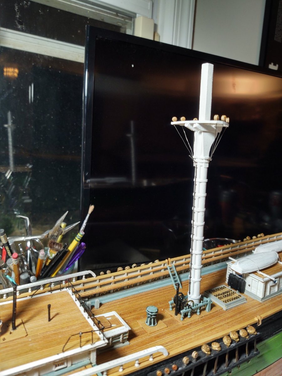
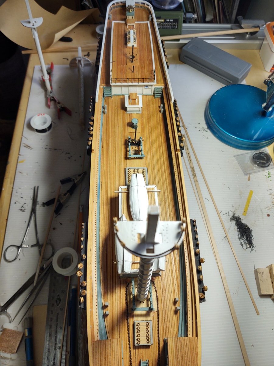
Finally the same shot of the whole ship, but with the focus on the deck, rather than the mast top.

Next up are the rest of the mast tops and futtock shrouds, and the belaying pins. Then the topgallant masts and I can start putting some shrouds in place.
As always, thanks for the likes and encouragement.
Please have a good Memorial Day weekend, however you choose to mark it.
Regards,
George K.
-
On 2/20/2022 at 6:48 AM, HakeZou said:
this assumes that the Discovery's funnel is the same color now as then).
Discovery has actually changed a lot from its 1904 appearance. The deckhouses have changed, two masts were moved forward various amounts to improve sailing trim, and the rig modified to use split topsails among other things. As to the color of the funnel, I can't really say...
Regards,
George K
-
6 hours ago, Vladimir_Wairoa said:
George , lovely milestone. one suggestion though. probably too late but it would be a bit nicer if deadeyes iron braces were a bit thinner. otherwise she is beauty
")
Yeah, the plans suggest 2 different sizes of iron plate and I had two sizes of brass, one that was 3" at scale, and the other 6" at scale. Using the 3" was probably too small for the shrouds and 6" too large. I don't have tools to mill the material to a smaller size and couldn't find intermediate sizes online. So, I decided to go slightly too large but retain the different sizes of plate.
The deadeyes themselves are also off a bit. There are something like 5 or 6 different sizes mapped to three sizes in the kit, so some of the mizzen deadeyes are too large and some of the ones on the tops are going to be too small.
One of the reasons I'm thinking about doing Discovery at 1:64 is so I don't have to deal with some of those choices, the 1/32"/0.5 mm spacing in commercial wood, brass, deadeyes, etc. is 2" then. Easier to get things properly in scale.
Regards,
George K
-
Well, I've reached a couple of milestones, although for whatever reason it was a much longer slog than was consistent with the actual technical/physical complexity of the task. So, the first milestone is that the chainplates are finally complete. As I mentioned before, the cuts in the channels for the plates were aligned to the plans so that the plates themselves should align with the path of the shroud or backstay. Because that means that getting the 'bolts' to align properly will require that each plate have a custom length, I put tape where I wanted the upper bolt to land, and drew a line on the tape where the lower bolt should sit. I then fitted the stropped deadeye with the plate, bent the brass as needed and marked the 'bolt' locations with a pin vise, drilled out the holes with a (power) hand drill, and opened it up further with a pin vise. This opened the hole wide enough without mangling it. You can see the 31 chain plates (11 fore, 11 main, 9 mizzen) in the photo below, with three sizes of deadeye and three different chainplate materials.
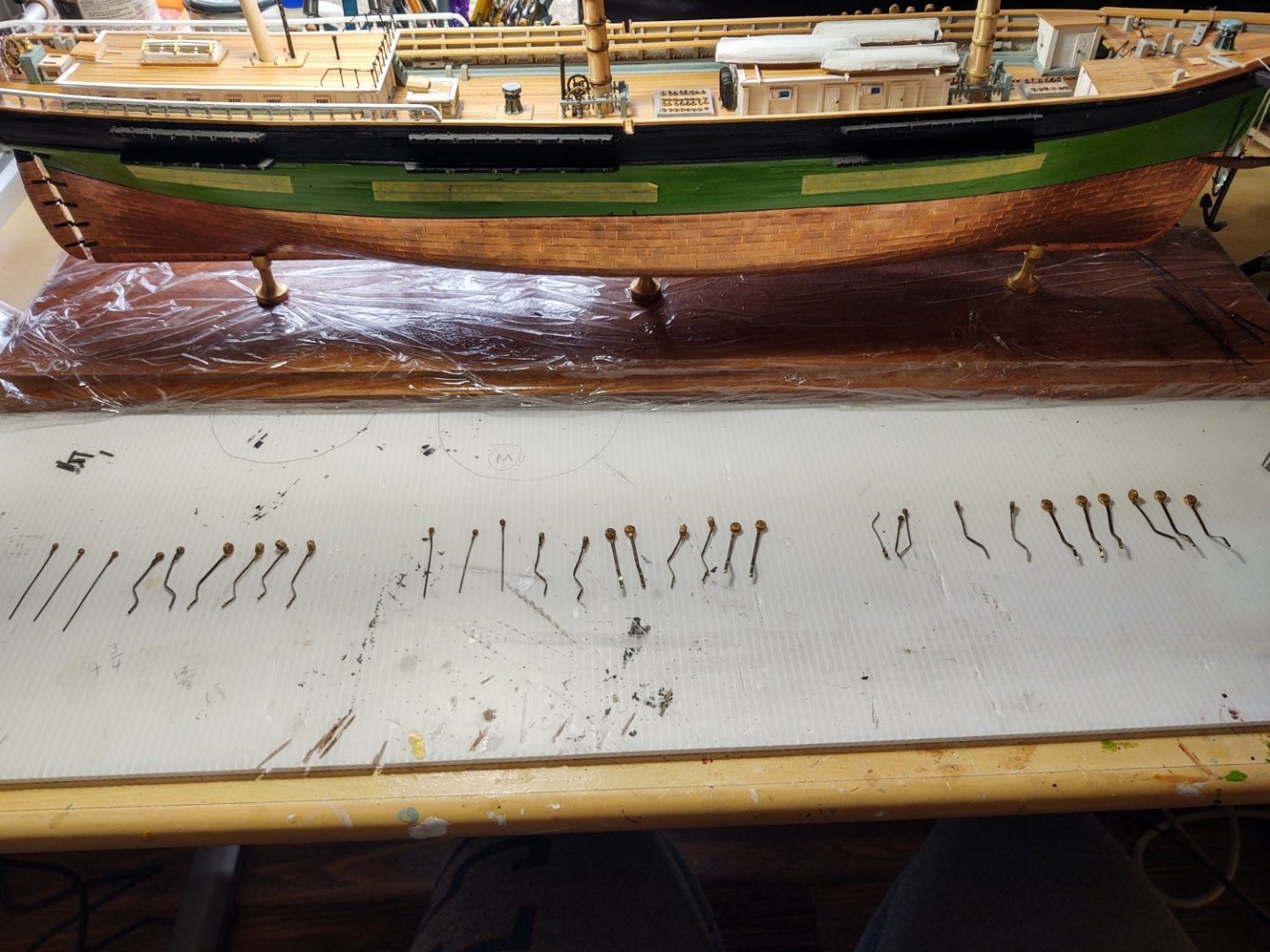
(Also the tape, which had to come off before I mounted them onto the hull).
After that, I glued each plate in place in the channels, and on the hull, covered the edge of the channels with a pre-painted black wood strip, and drilled the holes in the hull where the nail that represents the bolt would sit. The nails were then glued into plates. As mentioned before, the upper backstays are quite narrow, so rather than drill holes, I glued the plate to the hull, glued a short segment of similar diameter blackened brass below it, in line with the path of the plate to represent the preventer, leaving an approximately 1 mm gap with the chain plate. I then drilled holes above and below the "preventer" and glued the nails in. Here are some photos:

There are imperfections, but working ships had imperfections. That's my story, and I'm sticking with it.
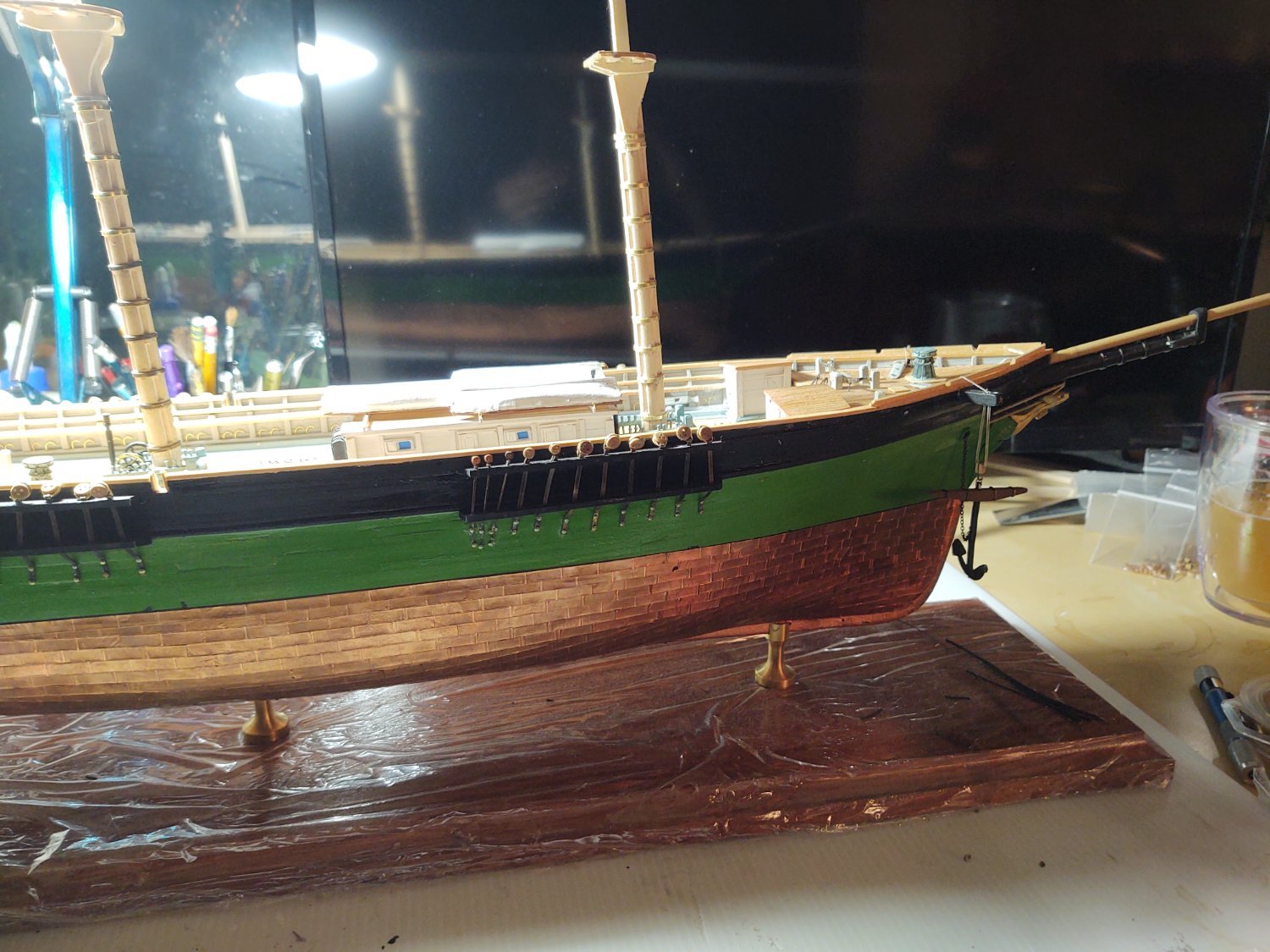
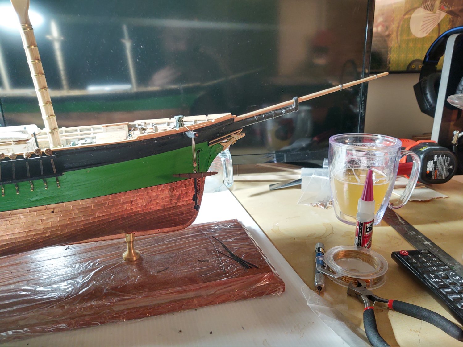
I also installed the irons on the jibboom and mounted it on the ship. It has the necessary holes drilled for the various lines that will eventually grace it, and the eyebolts that are representing the endpoints of much of the standing rigging on the bowsprit and jibboom.

Finally, the extra brass arrived from Model Shipways, and I've put the bands on the lower fore and main masts. They need only the bolsters on the tops and I can paint them white, and start thinking about installation. Here are three (not particularly good) views of the ship to date. The first from above showing the lower masts, the second showing the whole ship up to the bowsprit, and the third, a (poorly lit) view of the whole ship.


So, I still have some work on the main deck (tie down the ship's boats, build 4 ladders, attach the forward bell, blacken and install the belaying pins in the pin rail, but we are pretty much starting the transition to rigging, which is pretty cool.
One question for the cognoscenti. According to the plans, it appears that many of the connections between the bowsprit and the hull are mediated by hearts, rather than bullseyes or deadeyes. Shrouds and backstays seem universally to use deadeyes. On the Niagara the bowsprit standing rigging was a mix of deadeyes, bullseyes, and hearts. I assume that there was a reason for these choice, curious if anyone knows why.
As always, thanks for looking in and for the likes!
Regards,
George K
- BrianK, Cathead and Vladimir_Wairoa
-
3
-
Impressive Captain!
- hollowneck, Keith Black, FrankWouts and 1 other
-
4
-
On 5/8/2022 at 12:39 PM, bcochran said:
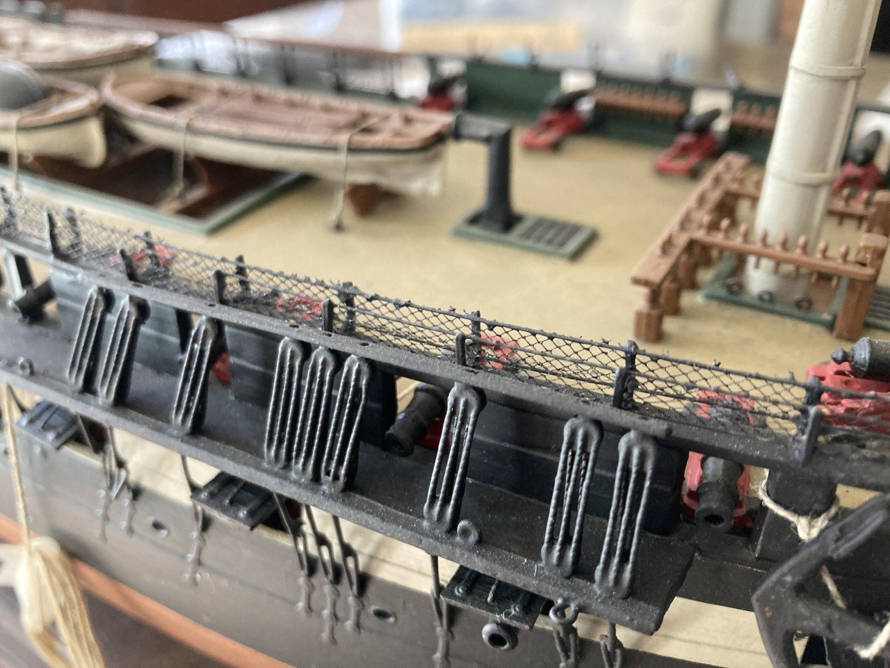
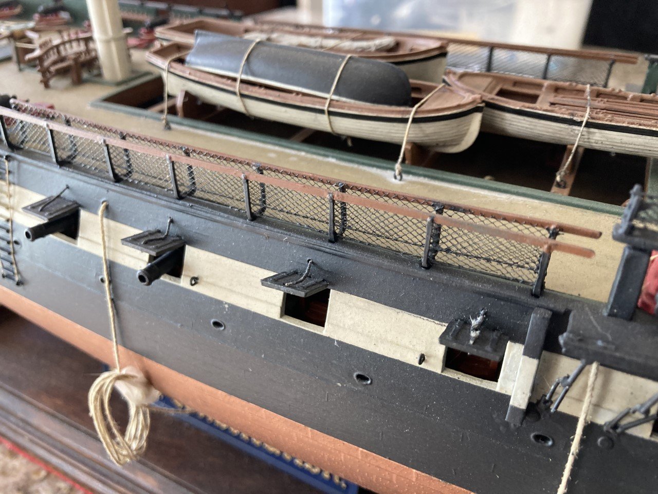
What is the large rope along the lower area of the bulwark for? It is hanging by ropes tied to the rail, I think. It might be some kind of protection against things crashing into the stanchions and such during rough seas. I read in Lubbuck's book of several times when the deck as completely underwater and all that could be seen from above were the masts sticking out of the foam. Items not tied down must have crashed into the firm stationary parts of the deck.
That photo doesn't look like it was taken while they had any kind of sails set. I see that it is lightly attached to the rails, but you might just as easily suggest it is a mooring line (I think I see it going into a chock in the upper part of the photo) being kept off the deck, perhaps to prevent it from sitting in water and rotting?
-
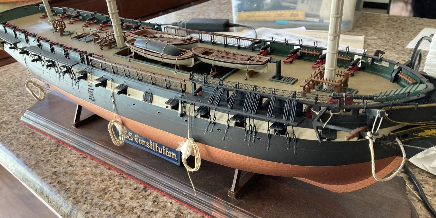
On 5/1/2022 at 7:29 PM, bcochran said:
Here are a few pics of the Revell USS Constitution I was working on before I started breaking parts off. I could not get the deck to look the way I wanted. I detailed the gun deck, even though you can't see it. I am anxious to do another one if and when my Cutty Sark is finished. I keep the busted Constitution on hand for inspiration.
In my stash of large ship models, uncompleted are the Heller Victory, Santa Maria, the Revell Yacht America, Kearsarge, Constitution and Lindberg Sea Witch.
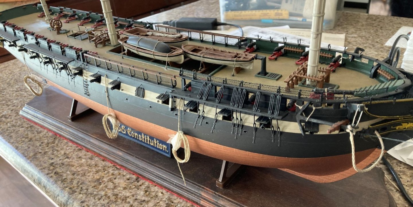
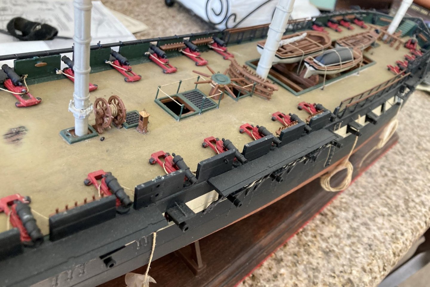
That's a great looking Connie! No reason to stop, everyone breaks things and had to repair. Once the basic hull is done, assume you are going to break something at least once every three sessions until the standing rigging is in place (it helps stabilize all those spars in the model as in life), at which point it'll drip to maybe 1 in 4 or 5 sessions. That's why we put them in cases (well and the dust).
I more or less mashed all of the rigging on the bowsprit and broke off the jibboom of my Niagara at one point (a story or almost mind boggling stupidity on my part). It was fixed and moved on.
Both ships are looking great!
George K


Flying Fish by Rick310 - Model Shipways - 1/96
in - Kit build logs for subjects built from 1851 - 1900
Posted
Didn't even realize you had surgery. Glad to hear you hit the first of hopefully many anniversaries!