

ggrieco
-
Posts
276 -
Joined
-
Last visited
Content Type
Profiles
Forums
Gallery
Events
Posts posted by ggrieco
-
-
Gerhard,
The engine is wonderful! I can't wait to see them in the model. Beautiful work!
Glenn
- WackoWolf, Gerhardvienna, mtaylor and 1 other
-
 4
4
-
-
Thanks Mike and Cathead,
Mike, The mill is very quiet with the small end mills I use. It hums in the background while I work and if I'm wearing headphones, listening to music I don't even hear it. It creates three sounds, the sound of the motor, the sound of the end mill cutting and the sound of the stepper motors moving the table. The motor is extremely quite. The smaller end mills barely make any noise but, as you go up in size, the vibration becomes more pronounced. The stepper motors produce the most noise - a buzzing sound that increases in pitch the faster they go. The feed rate for these smaller parts is slow enough that it is pretty quiet but as the parts get bigger and the feed goes up it can get a little annoying. At certain frequencies, the vibrations from the steppers will travel pretty far through the building so I have to adjust the speed and feed to keep it quiet.
-
-
Hello Gerhard,
I wish I had caught this build earlier but I know I'm going to love following it! A very interesting vessel with a lot of machinery - spectacular! Beautiful metal work and I loved your pivot carriages. I can't wait to see it all go together.
Glenn
- Canute, Gerhardvienna and mtaylor
-
3
-
Thanks everybody for your comments and likes. I wish I had the opportunity to thank everyone individually. I have never enjoyed building a model so much and been so inspired and I owe it all to the comments and support of the MSW community.
Thanks again!
Glenn
-
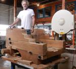
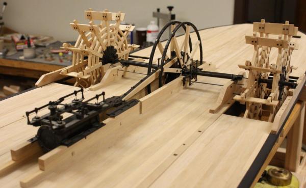
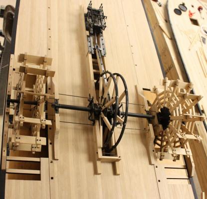
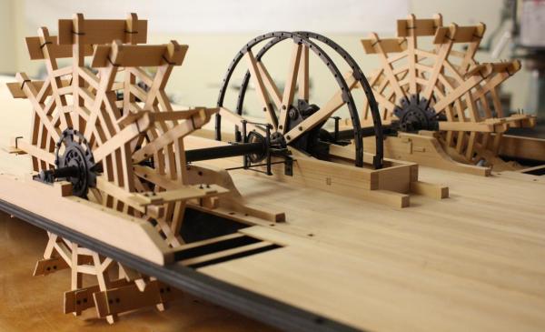
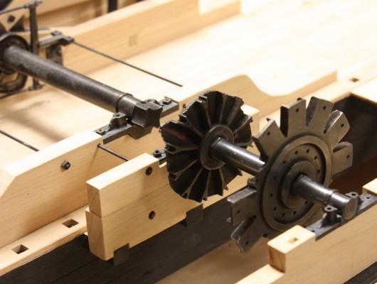
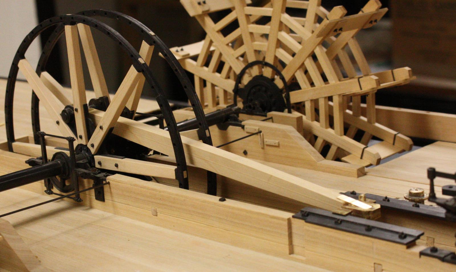
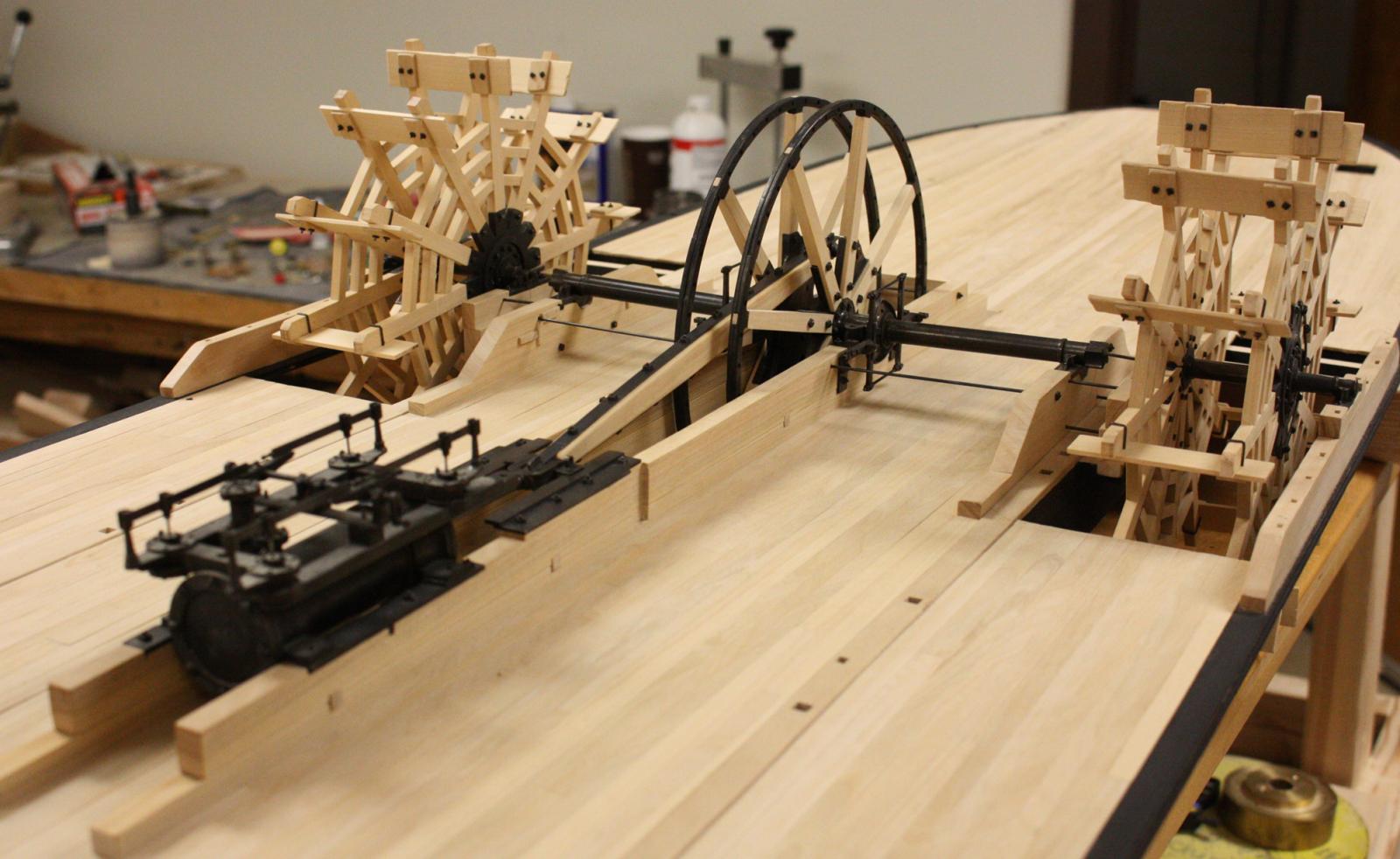
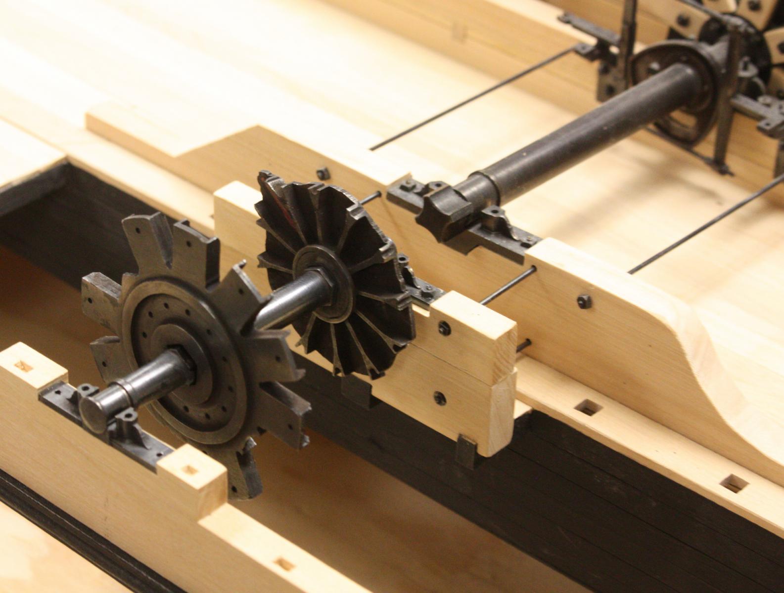
I finally completed the paddle wheels to the point I can start tying the drive train to the engine. This week I was able to get most of the pittman/crosshead assembly done. Just the feedwater pump and reach rods to finish before moving onto the boilers.
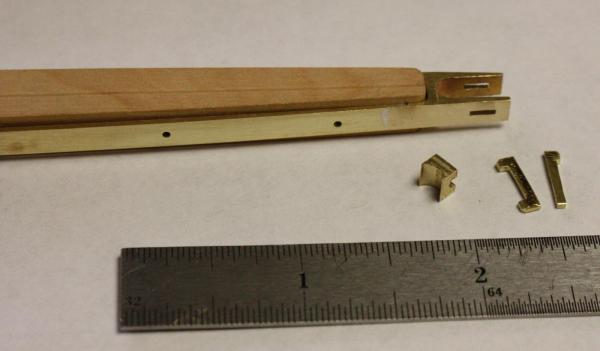
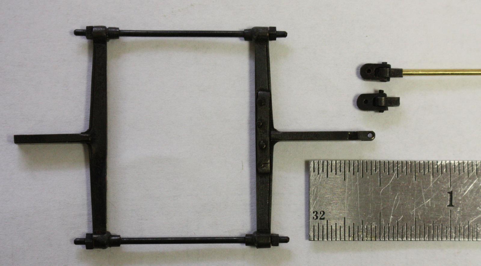
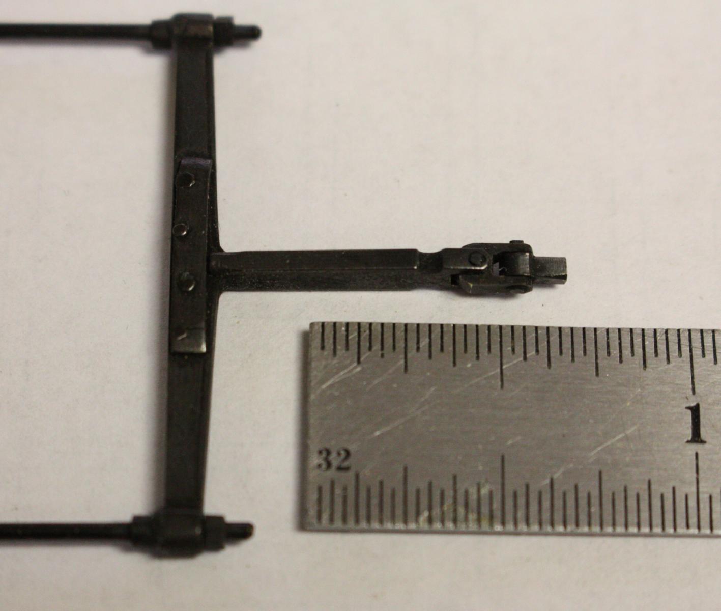
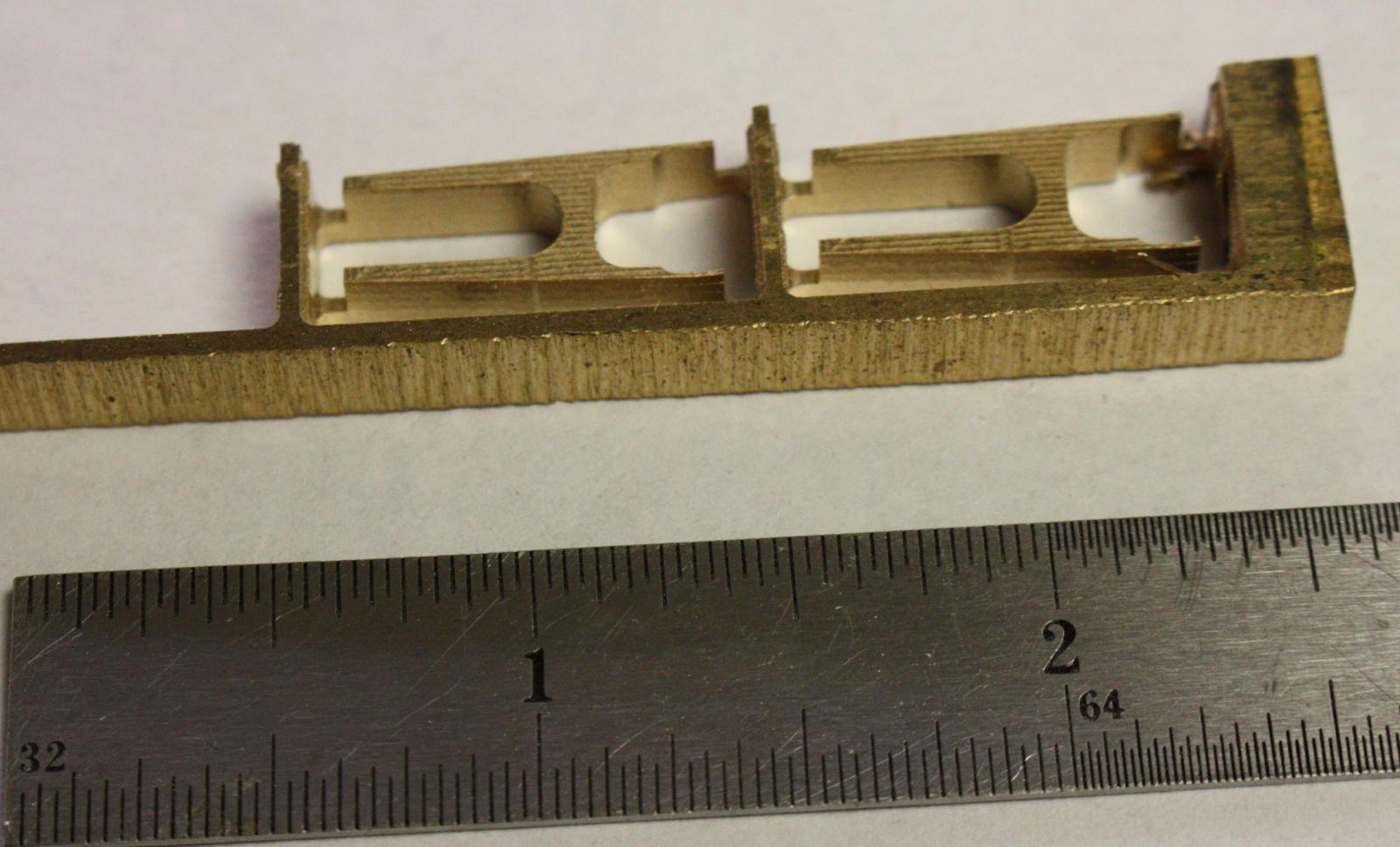
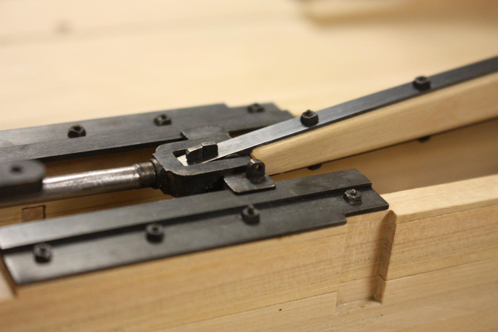
U-joints for the reach rods.
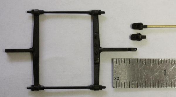
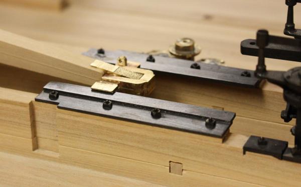
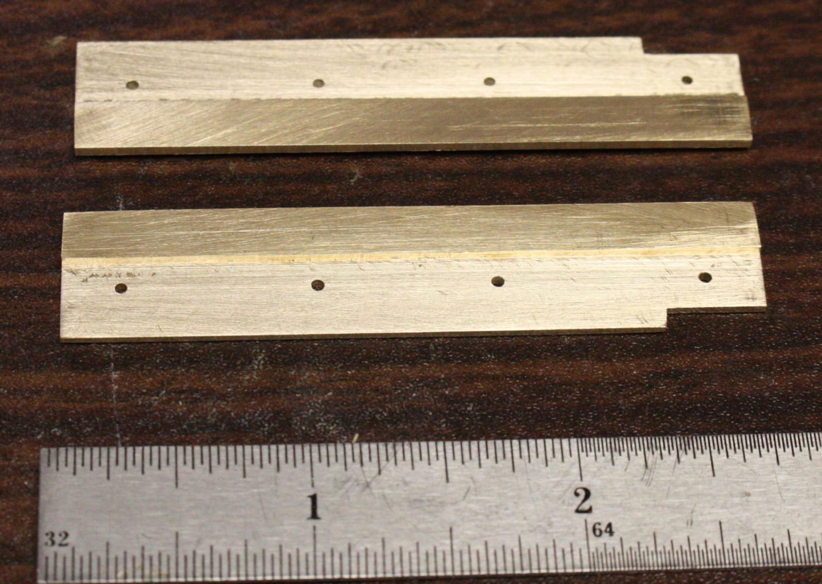
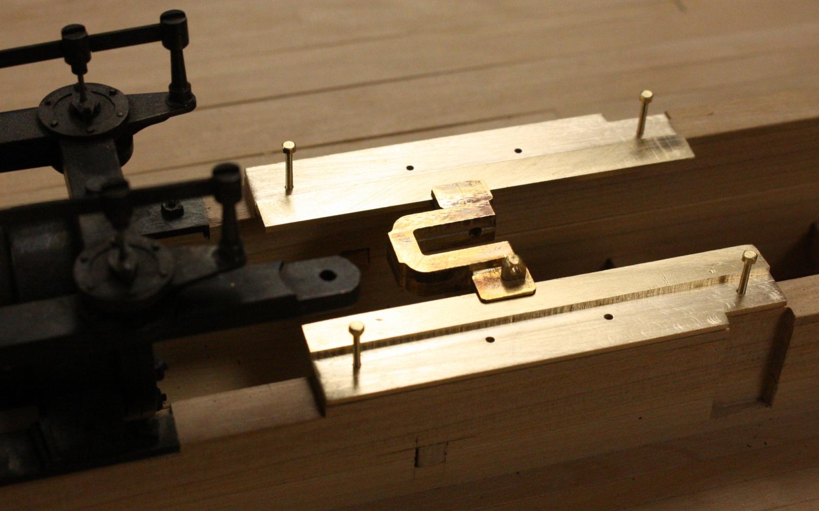
Crosshead slides.
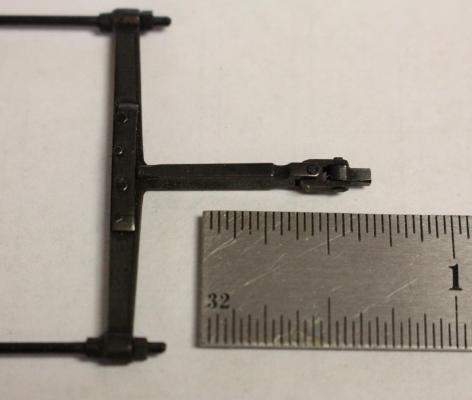
Testing the fit of the crosshead and end of the pittman.
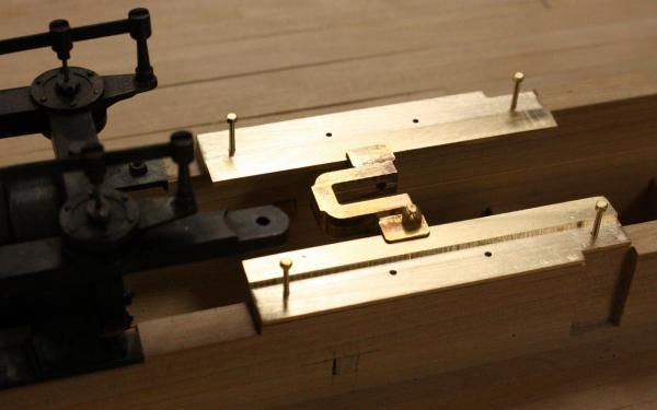

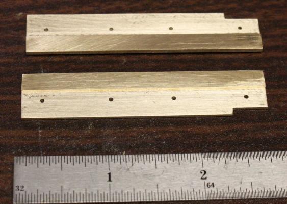
Pittman ends freshly milled.

Straps soldered to pittman ends.
Finished pittman strap with bearing, wedge and keys before blackening.
After blackening with bolts added.
Flywheel end of pittman.

Crosshead end of pittman.
- WackoWolf, cog, captainbob and 36 others
-
39
-
-
-
Thanks everybody,
Michael, I hope I haven't let you down. I cheated a bit with the u-bolt nuts. The hole is undersized and they are driven on tightly-- no threads. 00-90 is the smallest tap and die I have - too large for the 1/32 inch rod. So far, all the other fasteners have been threaded. Sorry about that.
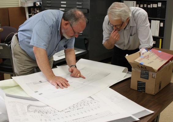
Cathead, Heroine's paddle wheels were 16 feet from spoke tip to tip. We haven't given the dimensions the full consideration that they need yet but your observations have started me wondering. I need to look back at the table in Adam Kane's thesis. I think he lists several vessels with the size of their paddle wheels. Hopefully, we can find a pattern.
Glenn
-
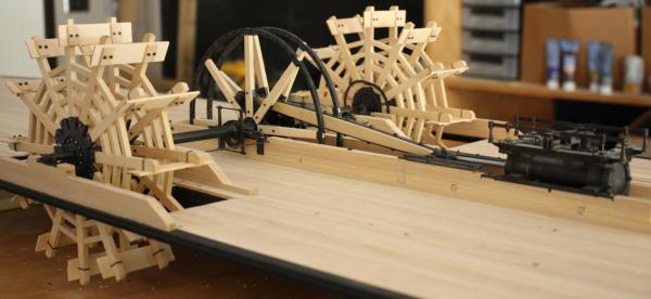
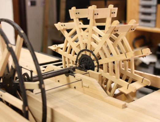
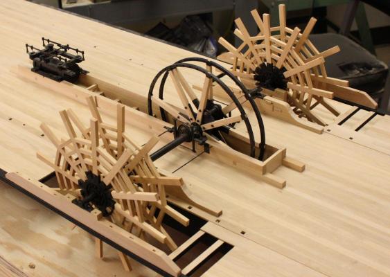
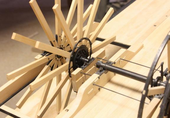
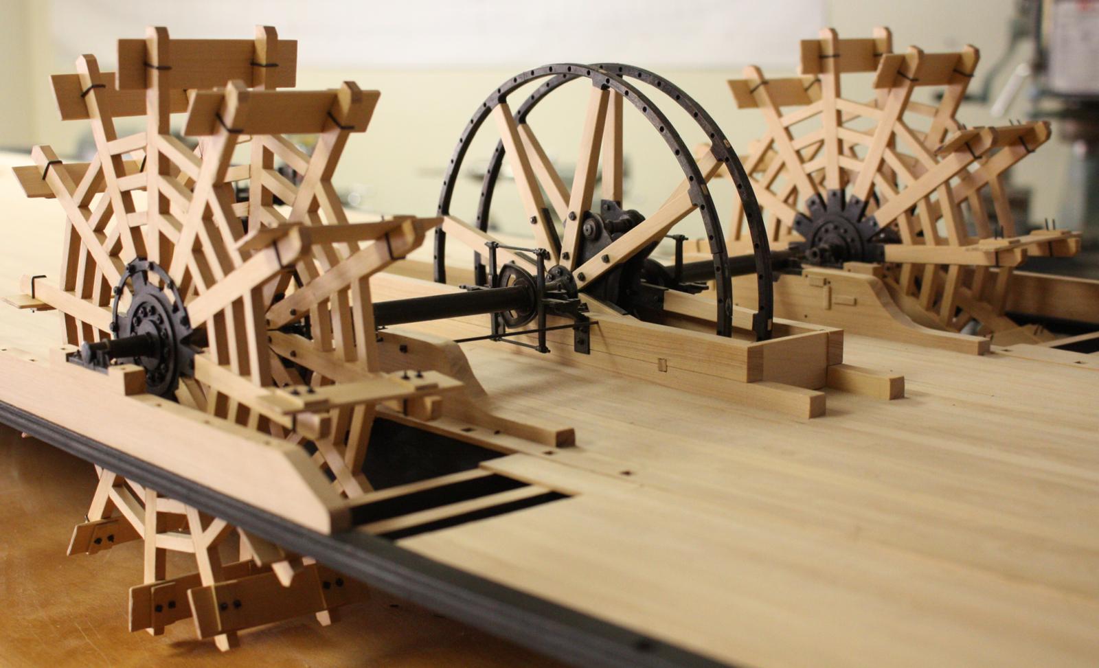
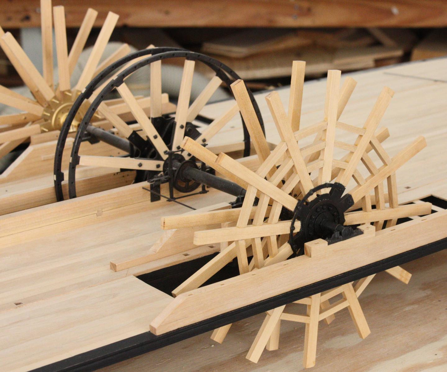
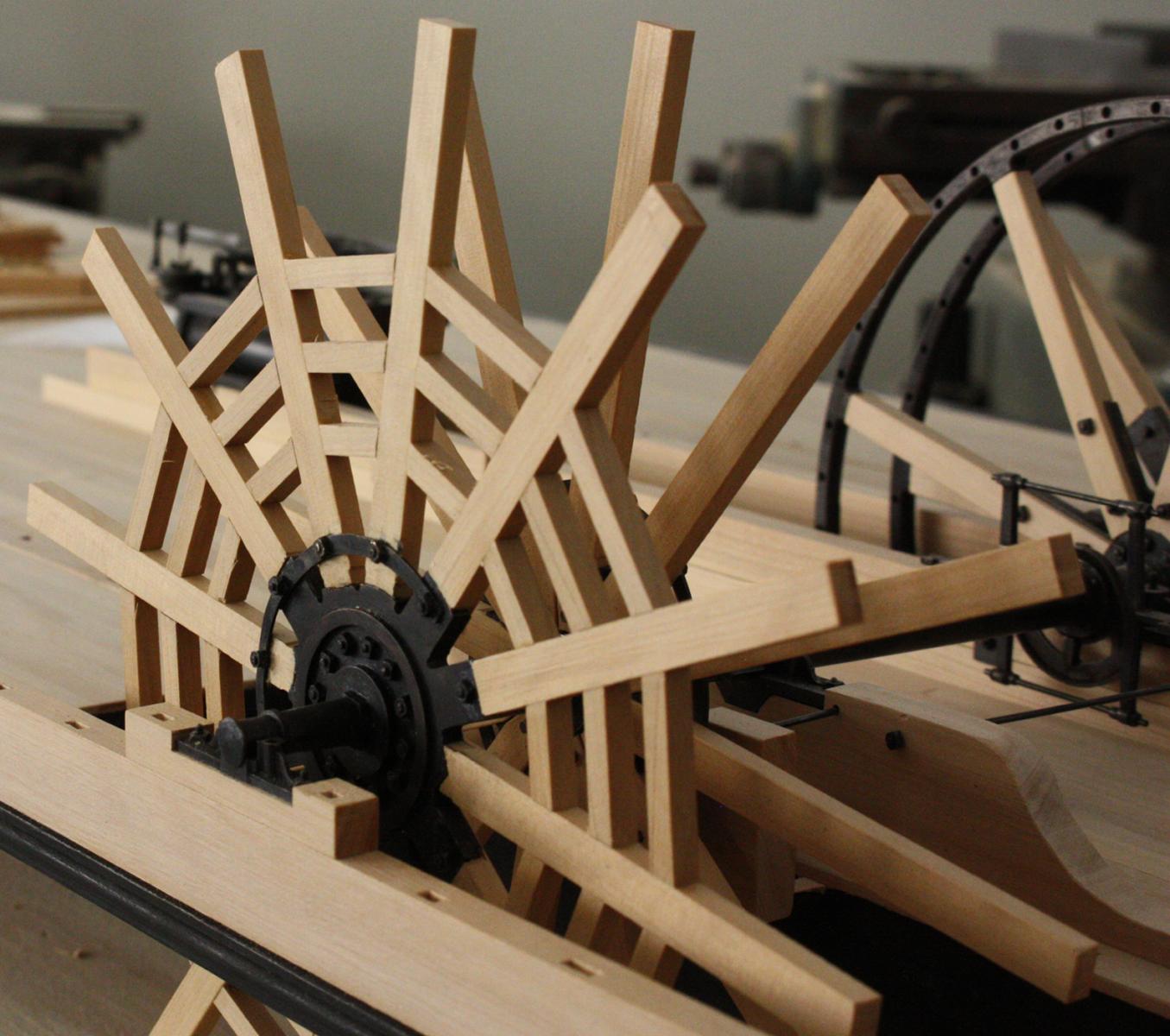
This week I tried to finish up the Paddle wheels. I just about made it, just the nuts on the starboard wheel to finish.
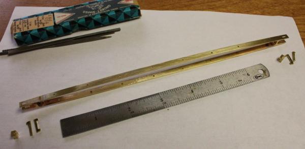
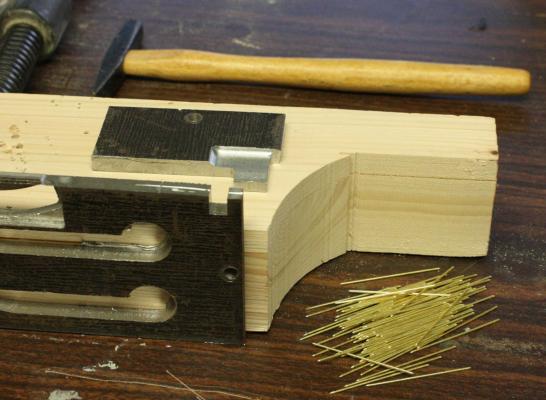
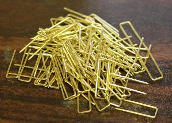
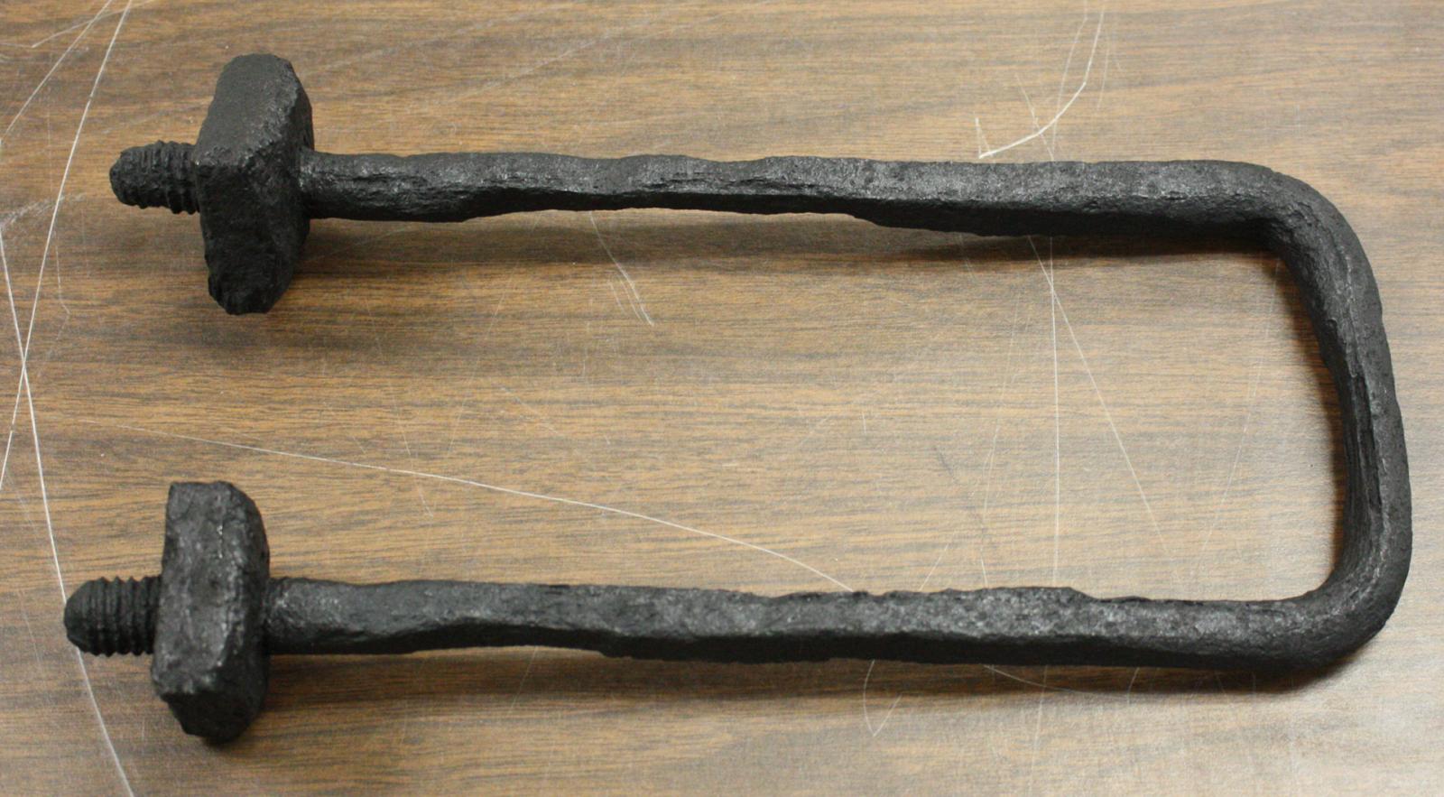
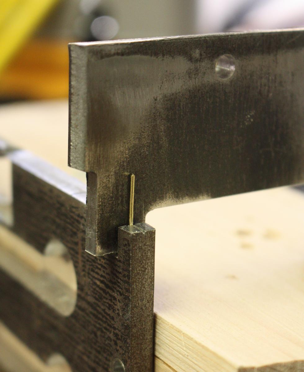
The buckets for the paddle wheels were 15 to 16 inches wide, 60 inches long and 1 1/2 inches thick. Each was attached to the spokes with two U-bolts. The U-bolts were about 3/4 inch in section with a 2 inch nut. Some of the bolts were entirely square in section, some were round and as in the photo, some were a little of both. I'm not sure if there was a reason for the nuts being put on flat side out.

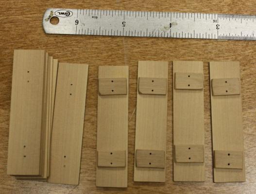
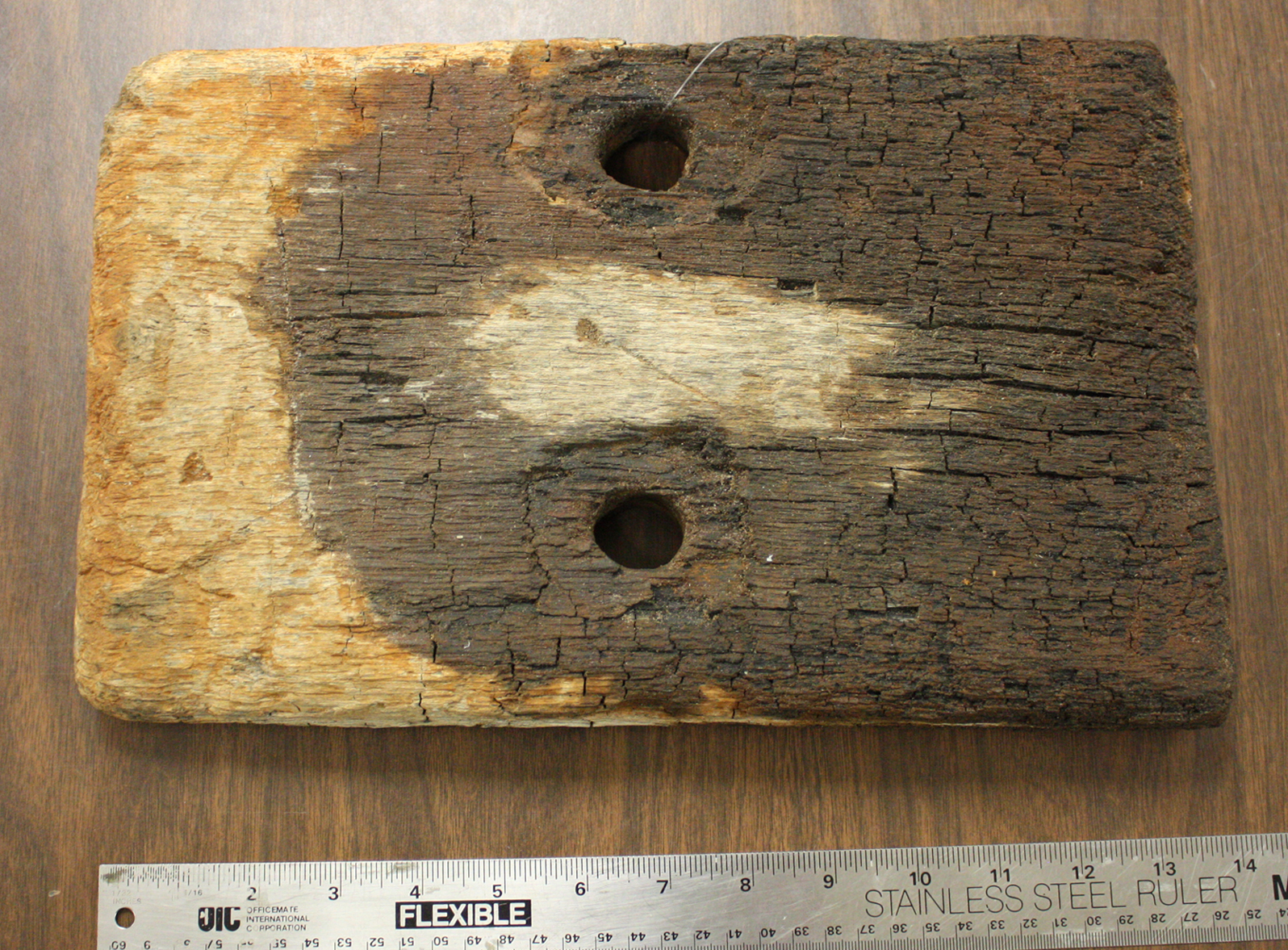
The area around where the bolts went through the bucket was reinforced with a short plank about 14 inches by 8 inches by 1 1/2. Sizes varied and the seemed to be crudely cut.

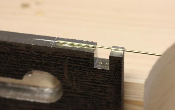
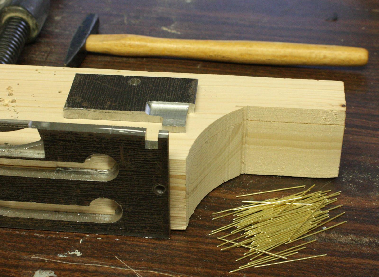
I made several attempts to bend the u-bolts by hand but I couldn't get them to sit properly against the spokes. I made a simple jig to swage each bolt and it worked well. I was able to make the entire pile of 96 in less than a half an hour.

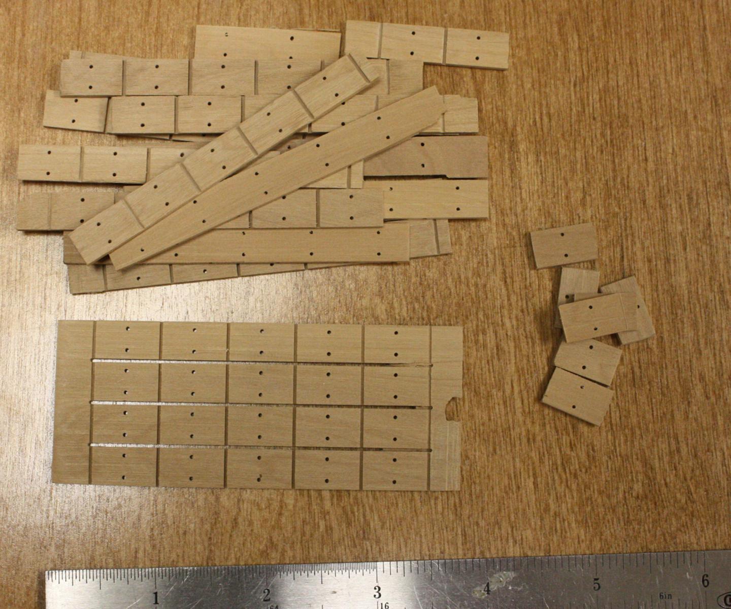
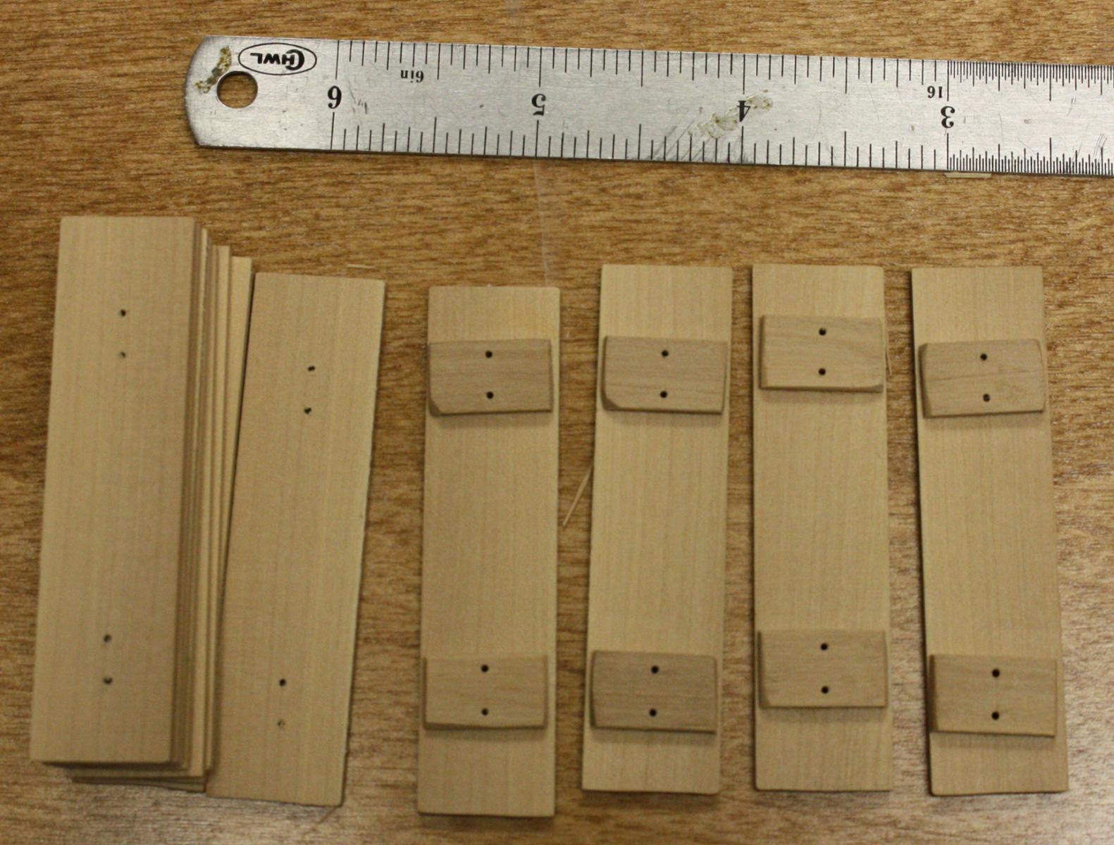
The individual pieces of the buckets going together.

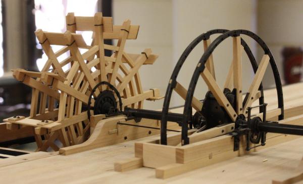
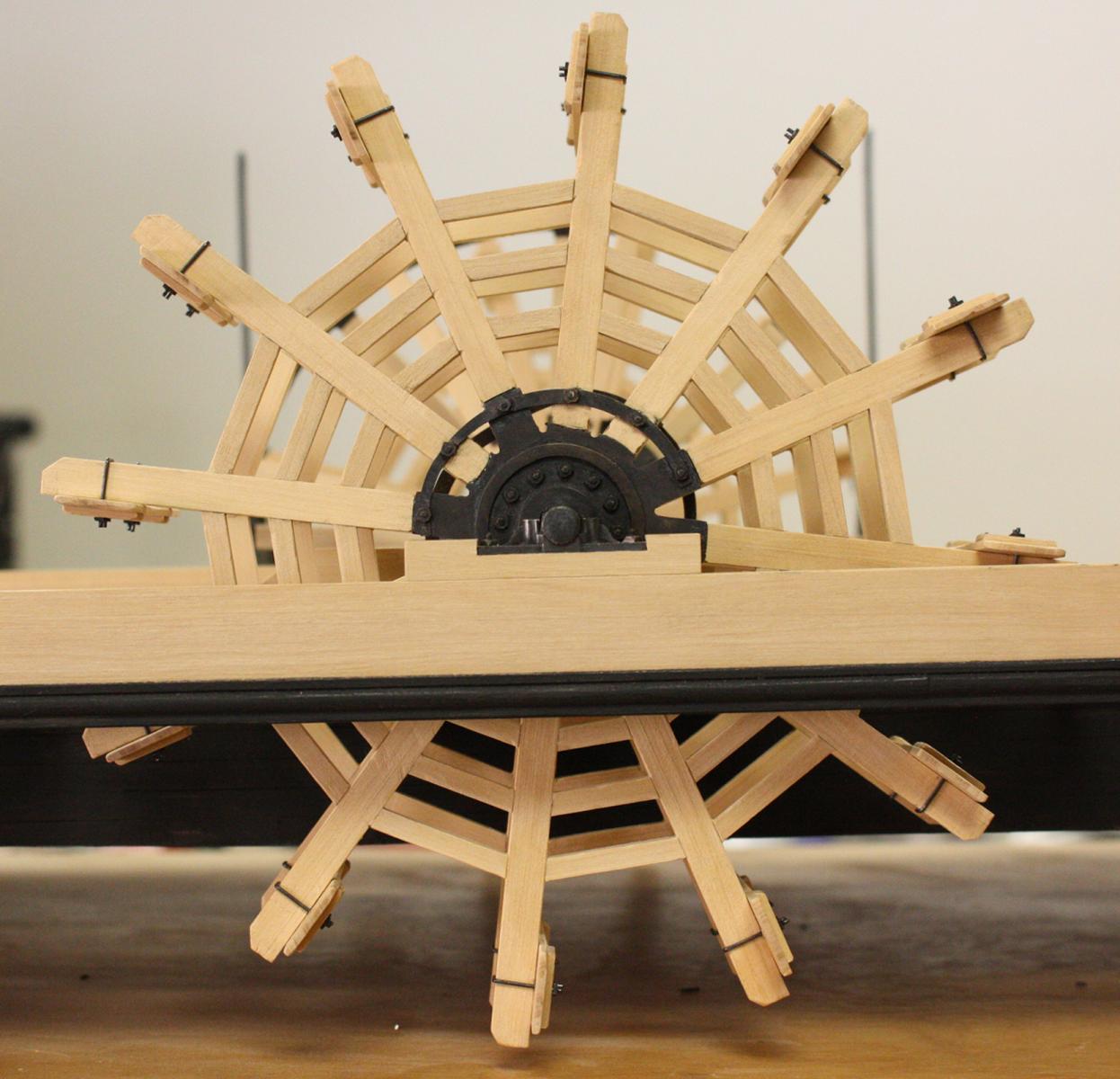
The completed port wheel (minus the throw-out bearing) and the almost complete starboard bearing.

Kevin and I had the pleasure of a visit from Mitch Michelson this week. Mitch, we enjoyed the day and hope to see you again soon.
- dgbot, Wintergreen, captainbob and 27 others
-
30
-
This last week was Spring Break for us. I took a few days off so I didn't get much done. I was able make a little progress on the paddlewheel. They just need the buckets and they will be complete. Hopefully, this next week will be a little more productive.
-
Thanks Mark, druxey, John and Bob,
Mark, although the flywheel didn't seem to show much damage, just about every other aspect of the machinery had extensive pre-wreck repairs. The paddle wheels were a mess with patches and shims barely holding them to their shafts. In fact, the flanges had slipped off of their hexagonal bosses and the resulting gap between the flange and shaft was packed with both wood and iron shims. The crew was using just about anything they could find to hold the flanges in place. We also have a piece of bent copper that was used as a makeshift replacement for one of the bronze shoes on the cross head. The cams were also improperly seated and just made contact with the edge of the cam frames. They were about about 3/4 of a inch away from slipping out of the frames and binding the whole system. Another repair that I left our was a stack of timbers under the outboard bearing of the port paddle wheel. With all the bearings in line, the outboard end of the deck beams were 12 to 14 inches below where they should be. As the guard sagged over time three timbers were added one by one under the bearing timber to compensate. The outboard end of the deck beams supporting the paddle wheels were probably very close to dragging in the water.
John, thanks for the correction, I'll keep it in mind when I experiment with the water.
-
Thanks Greg,
I had a lot of fun building that one. I just wish we had the entire wreck at the time. I'll always look at it and think half of it is missing.
Glenn
- Bobstrake, michael mott, Omega1234 and 4 others
-
7
-
-
Thanks Kurt, Steven, Andy and John,
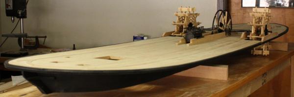
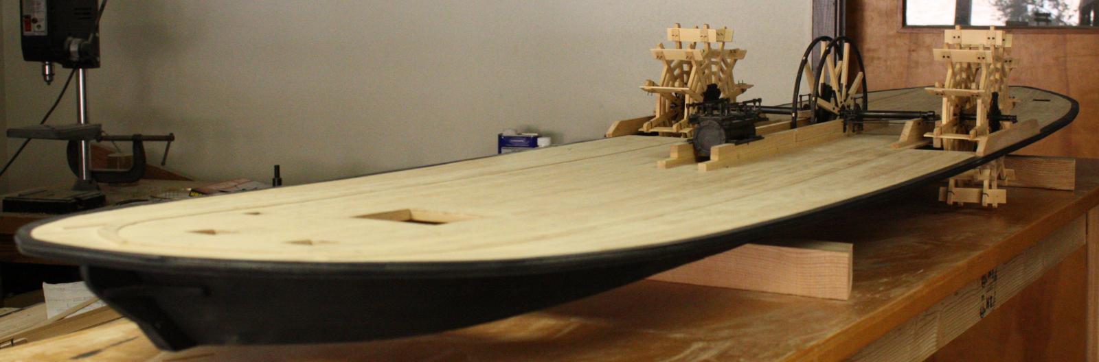
John, great idea! This is how I'll handle the rest of the wheels. I think I will leave the base cutaway on the port side to see the entire wheel but the starboard paddlewheel on the first model and the flywheel and starboard paddlewheel on the second model will all be recessed like this. Thanks for the photos. Do you mind if I ask if you textured or painted the waters surface?
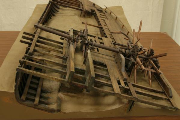
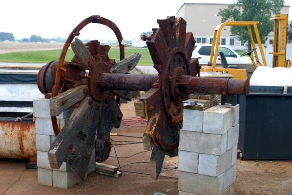
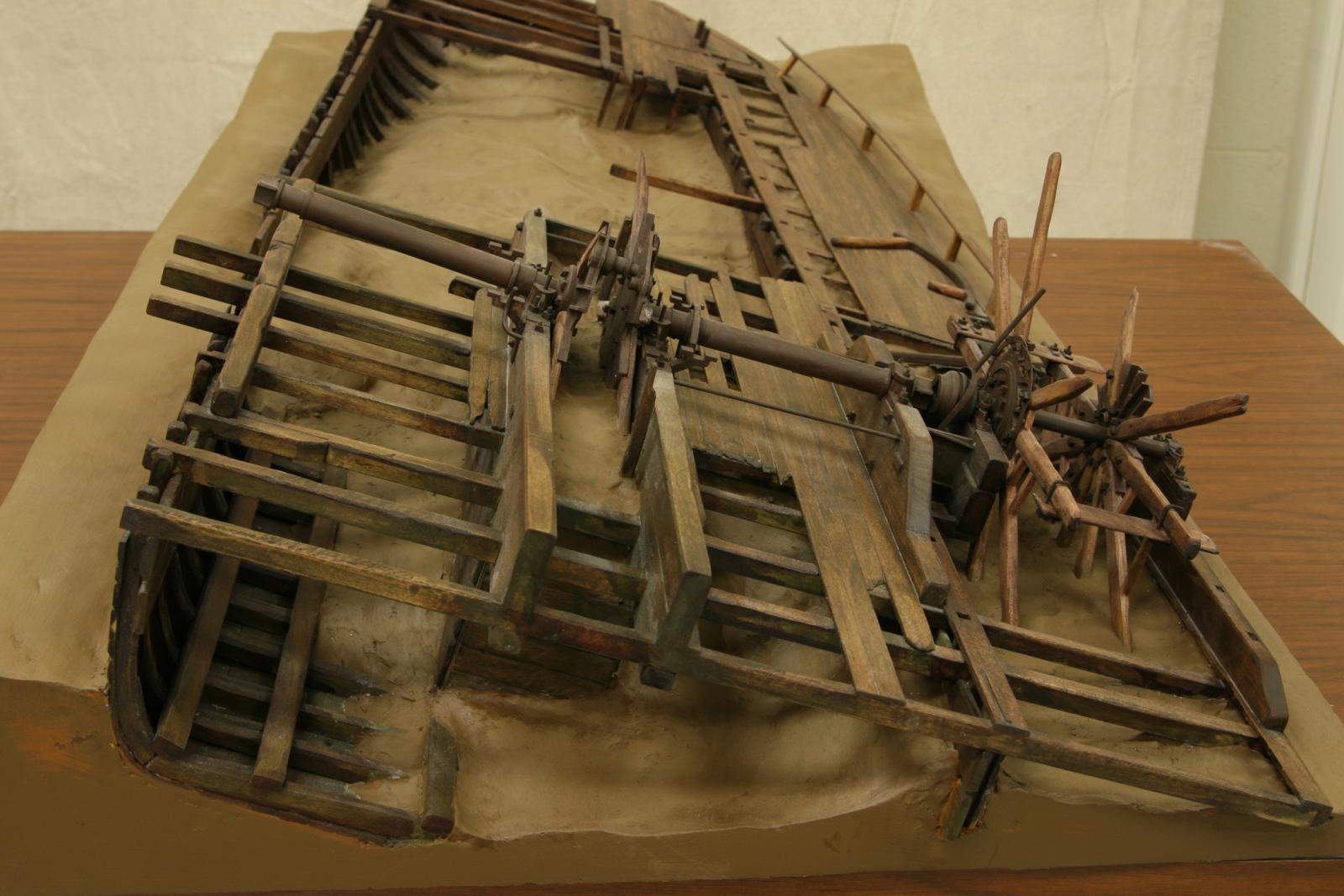
Kurt, I'm attaching a couple of photos of my first sectioned diorama to show the extent of the wreck. I'm also including some photos of the original paddlewheel assembly and associated bearing to show how badly the shaft was moving around in the bearing. I don't know how they trusted this to hold together!
Thanks again for your comments and ideas.
Glenn
My first diorama of the Heroines remains. At this time the forward half of the vessel hadn't been excavated yet.
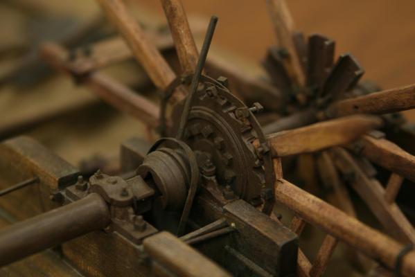
Close-up of the clutch mechanism. I will be modeling this next.
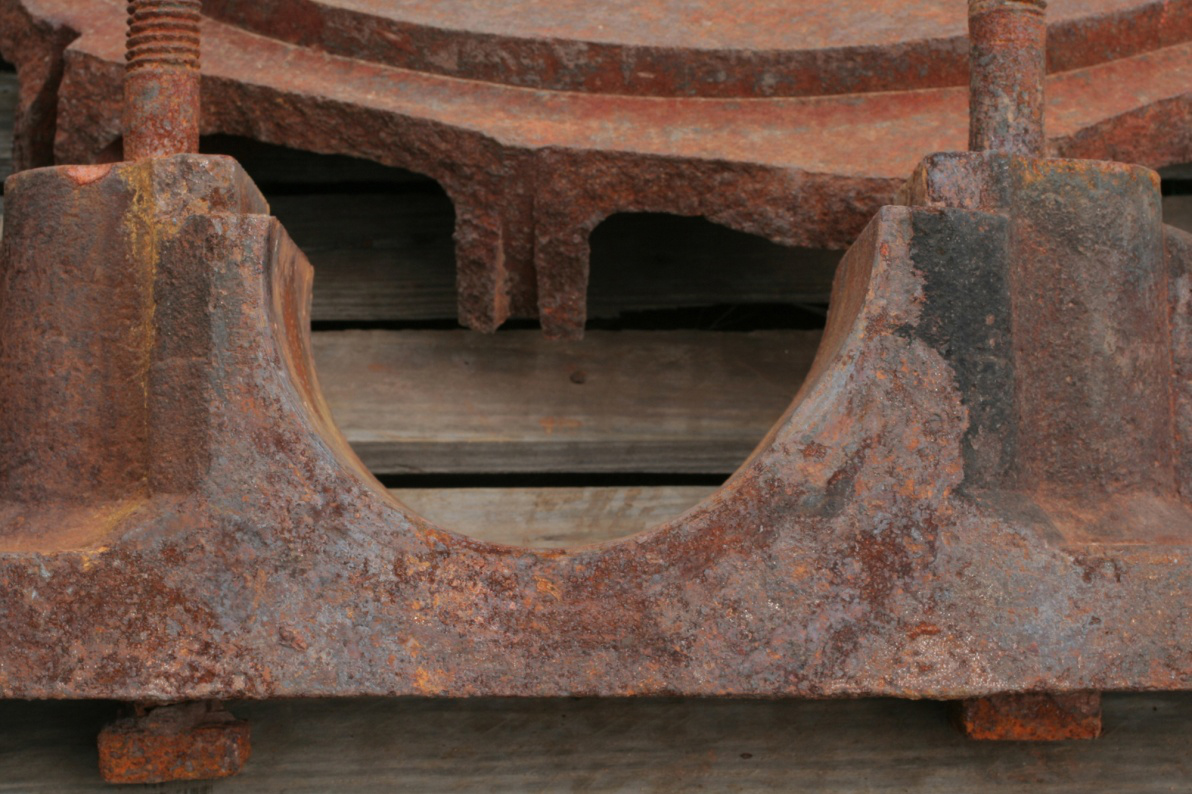
Port paddlewheel before conservation.
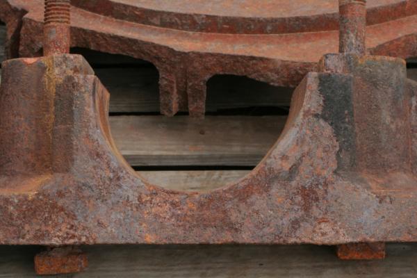
Outboard port paddlewheel bearing. Oddly, instead of having bronze sleeves, this was the only bearing cast entirely of iron without a separate bronze lining. You can even see the part line where the iron should end and the bronze should start. The shaft also wore away the after edge of the bearing surface. The shaft must have moved in the bearing with any change of momentum or force on the shaft. With over a ton of wood and metal bouncing around it must have made for a bouncy ride.
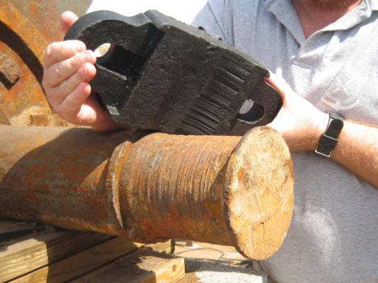
Associated bearing cap showing wear to aft side and matching wear on shaft. All the caps were cast with a grease cup on top. This cap was the only one that wasn't bored with a hole in the bottom of the cap. It appears that they felt no need to grease this bearing.
-
Hello druxey,
I just want to mention how much I've been enjoying this build. I don't get a chance to check in as much as I like - when I get home from work, my daughter is usually hogging my iPad to play my little pony. I do look forward to the weekends when I can get a chance to check on your progress. It is amazing!!
Glenn
-
-
I love bomb ketches and you are doing an incredible job with this one. I don't get a chance to check in as much as I like but I always look forward to your posts. I love the mortars!
- Bobstrake, paulsutcliffe, mtaylor and 2 others
-
5
-
Thanks Cathead, druxey and Jack,
The damage lets me off the hook for keeping everything lined up exactly. It all comes down to how much slop I should represent. Not enough and I don't represent the remains well, too much an the structures look unattractive or poorly modeled. I'm afraid that if I represent the remains in the condition they were actually in, no one would believe it.
Glenn
-
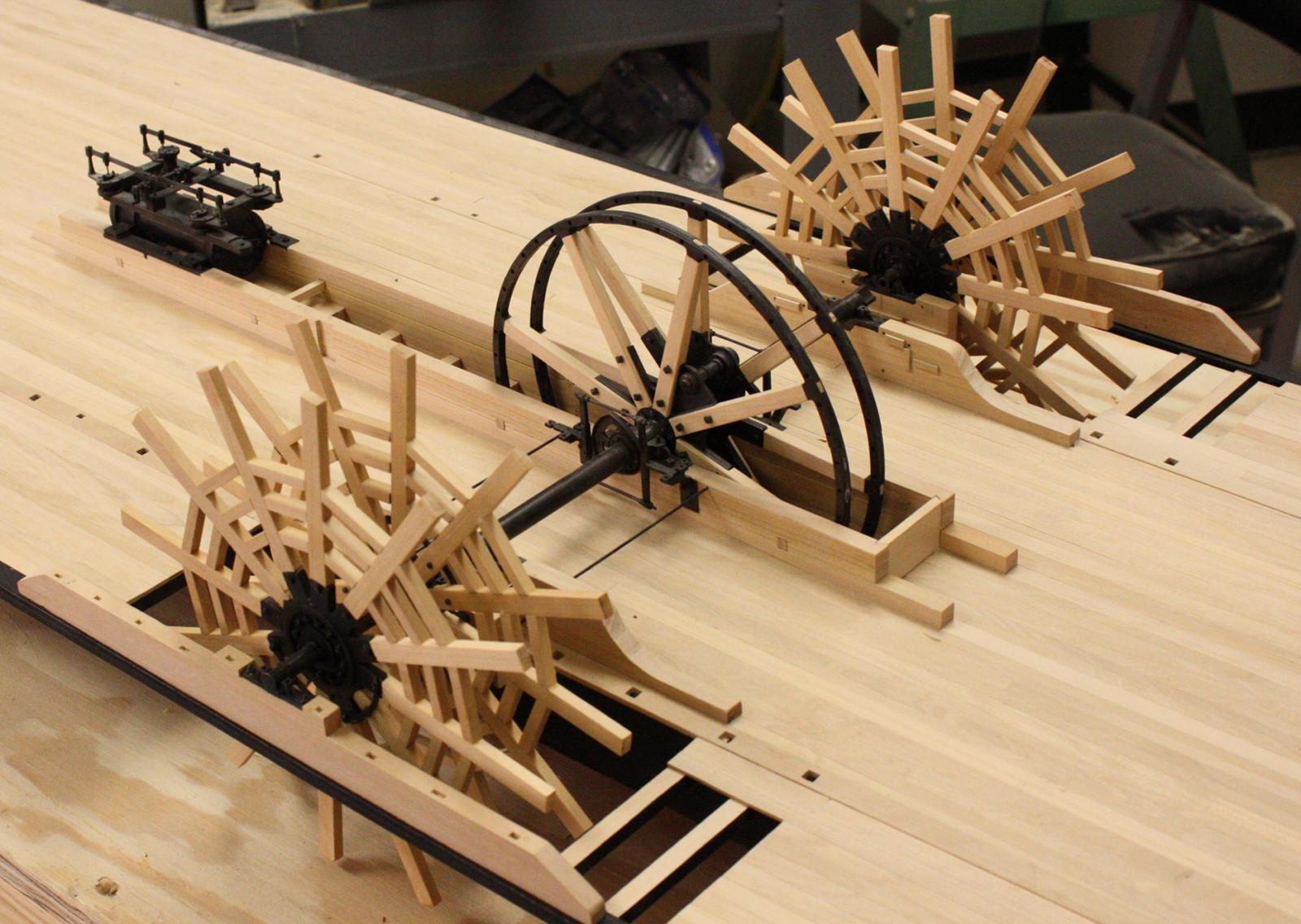
I wanted to thank everyone for the suggestions on modeling the water surface. I spent the week trying to come up with something and I think I'm leaning towards the woodland scenics approach. I have a lot of surface to cover - it could get expensive.
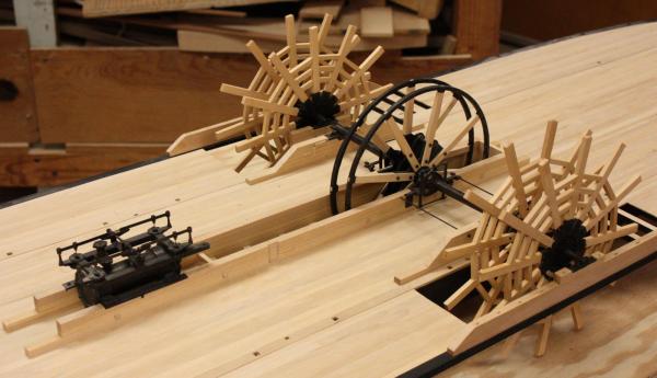
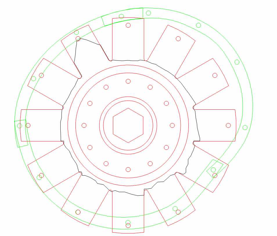
This week I tried to reproduce the damage done to the paddlewheels. Every paddlewheel had some damage to it. The channels that hold the spokes were broken off in several locations and repaired with custom made forged iron straps. The inboard port flange was the worst with all the channels broken off.
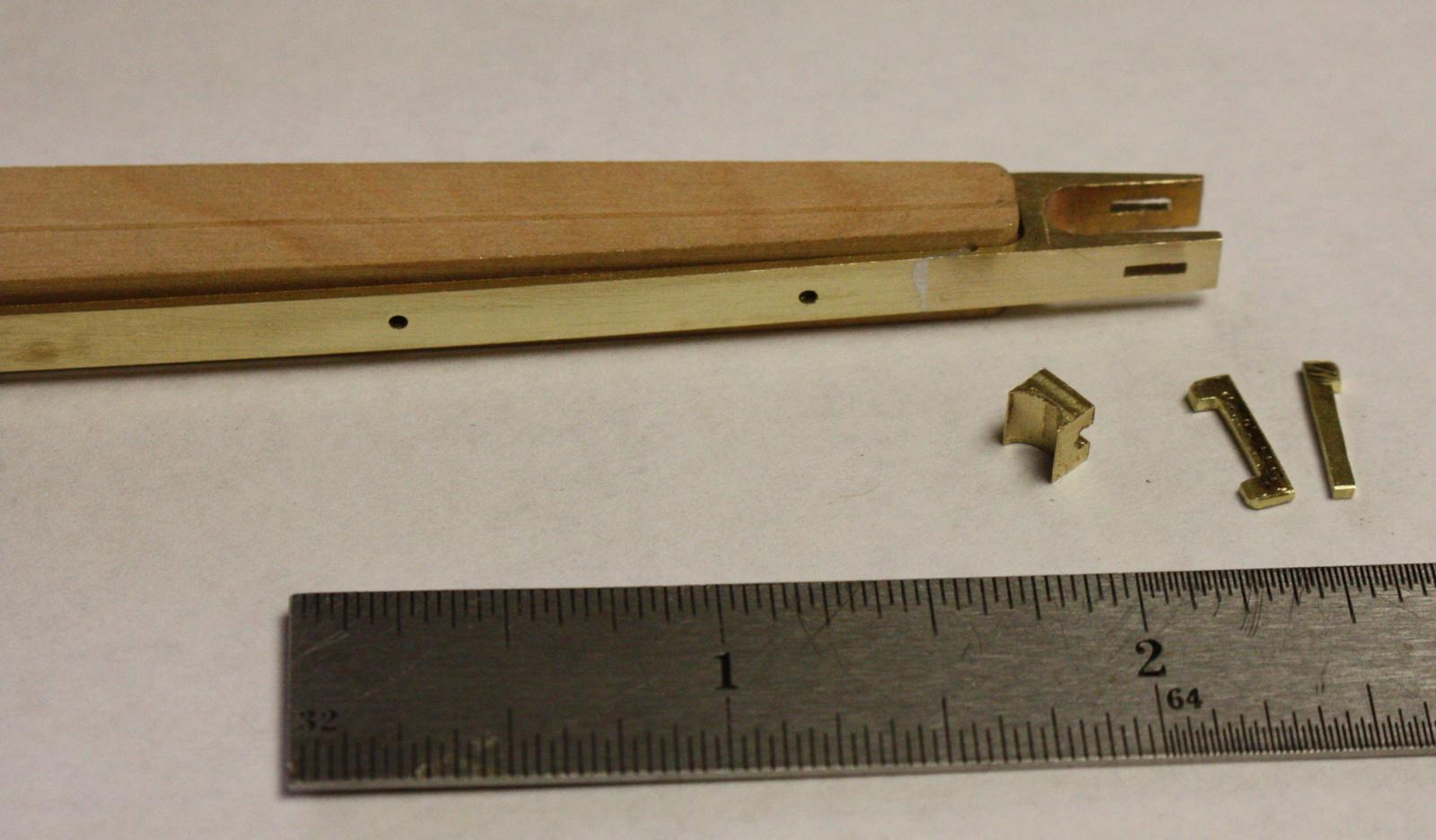
Inboard port paddlewheel flange and straps. Black outline shows the extent of the damage.
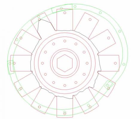
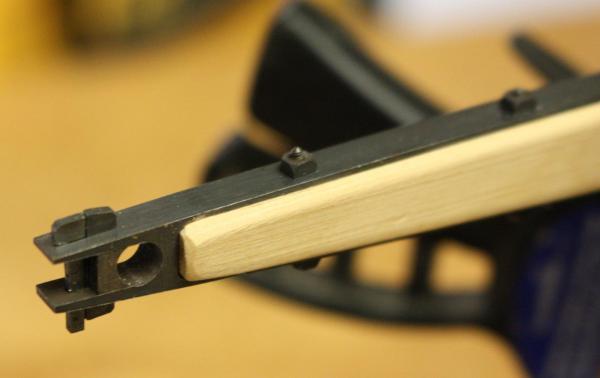
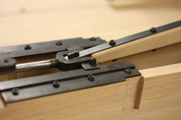
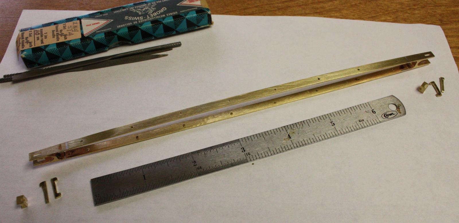
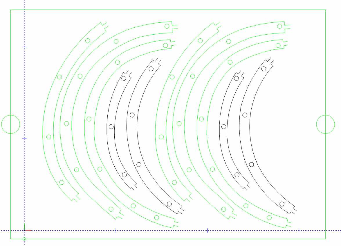
Strap layout for the mill. Green outlines are for the inboard flange, black for outboard.
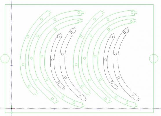
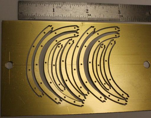
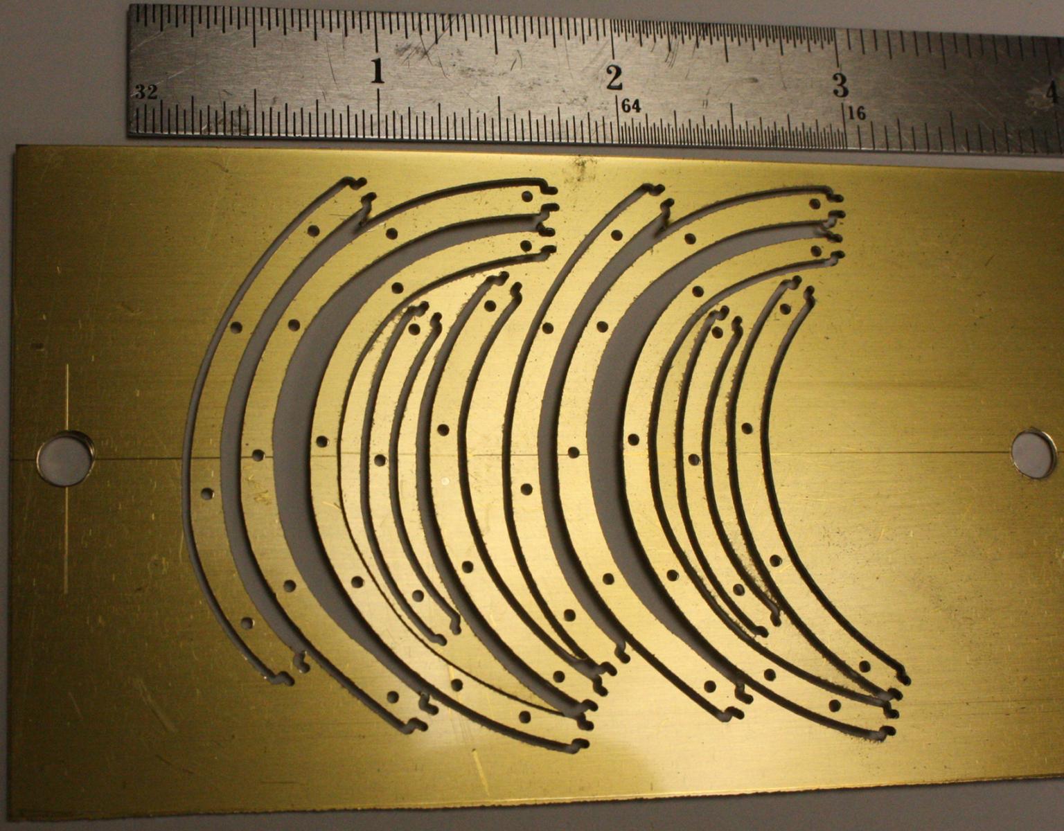
Straps milled in brass.
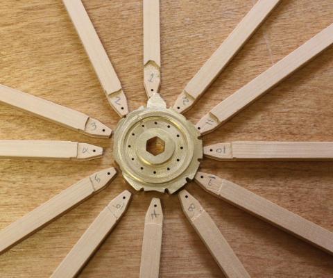
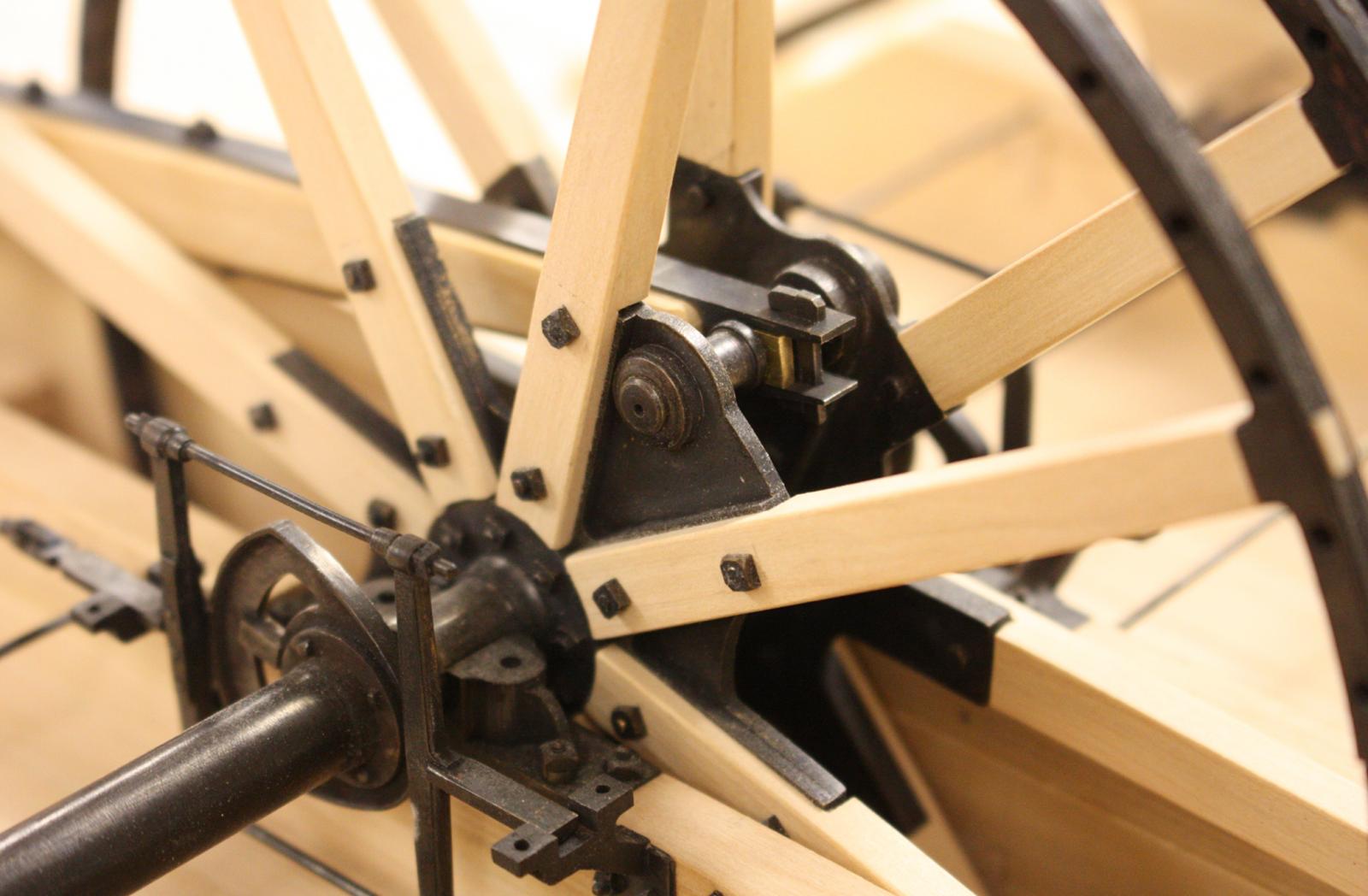
Fitting inboard paddlewheel spokes.
Flanges soldered to shaft and blackened.
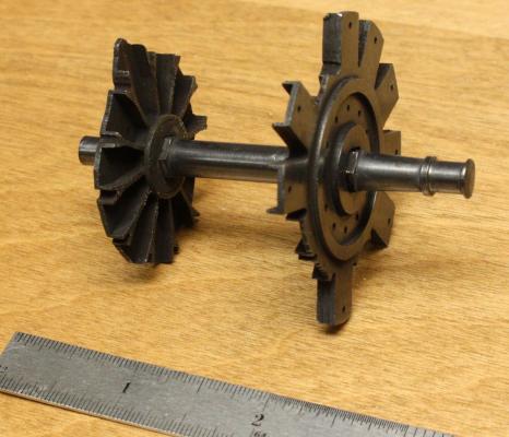

Spokes and staps in place.
Wooden spreaders added between spokes. 36 down 252 more to go.

I rushed to take photos and forgot to clean up the timbers. Looking a little hairy in this photo.

-
-
Thanks Cathead,
Great idea about the railroad modelers, I'll start looking around. You're correct as well about the muddy color of the Red River. When we were diving on the wreck, visibility was 8 inches or less and all our equipment would quickly fill with sand. There was so much sand suspended in the water that you could'nt see anything a few inches below the surface. It lets me off the hook a little about a deep transparent effect. A muddy chocolate color is definitely the way to go.
Glenn
-
Thanks Everyone,
I think I will go with the plinth idea but I'm still trying to put it together in my head. Luckily, the amount that I was going to cut off was less than two inches so there isn't much height to make up for. My big question is how to paint and texture the surface of the water. I have never done water before and I'm entirely in the dark about what technique I should use. I've seen textured glass, Magic Water, painted acrylic resin and several other methods. Whichever l use will probably require a different underlying structure. Can anyone suggest a technique that is both believable and doable for a first timer?
Thanks again for your comments and advice, now I'm off to do some work in the garden. 18 tomato plants and an irrigation system to put in.
Glenn


Majellan by Omega1234 - FINISHED - 1/200 - Luxury 37 m Motor Yacht - Miniature
in - Build logs for subjects built 1901 - Present Day
Posted
I've only missed your build for a week but your progress has made it seem like a lot longer. So much incredible detail so quickly. Nice work!