

ggrieco
-
Posts
276 -
Joined
-
Last visited
Content Type
Profiles
Forums
Gallery
Events
Posts posted by ggrieco
-
-
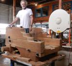
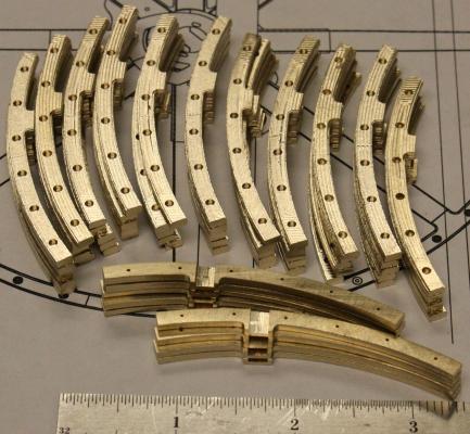
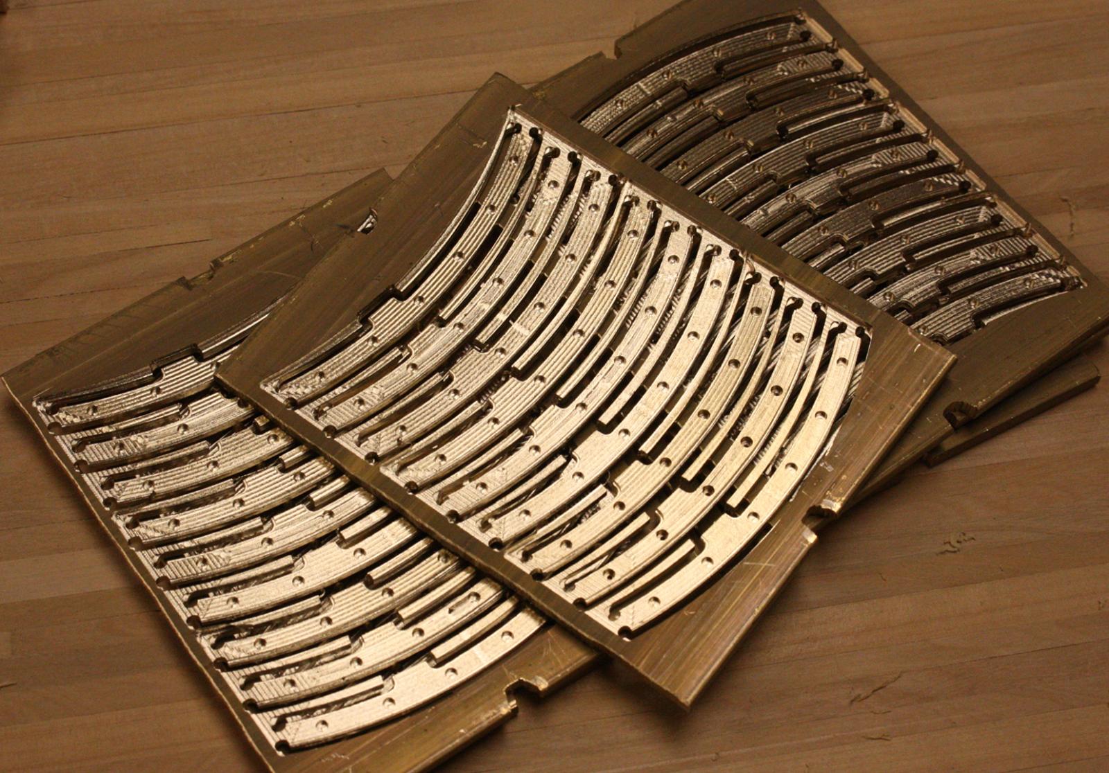
I've finally gotten around to making the flywheels. I've been looking forward to it because it is the largest and most impressive piece of machinery that was recovered from the wreck. Heroine's two flywheels were 14 feet in diameter and each was made up of 16 overlapping identical castings.
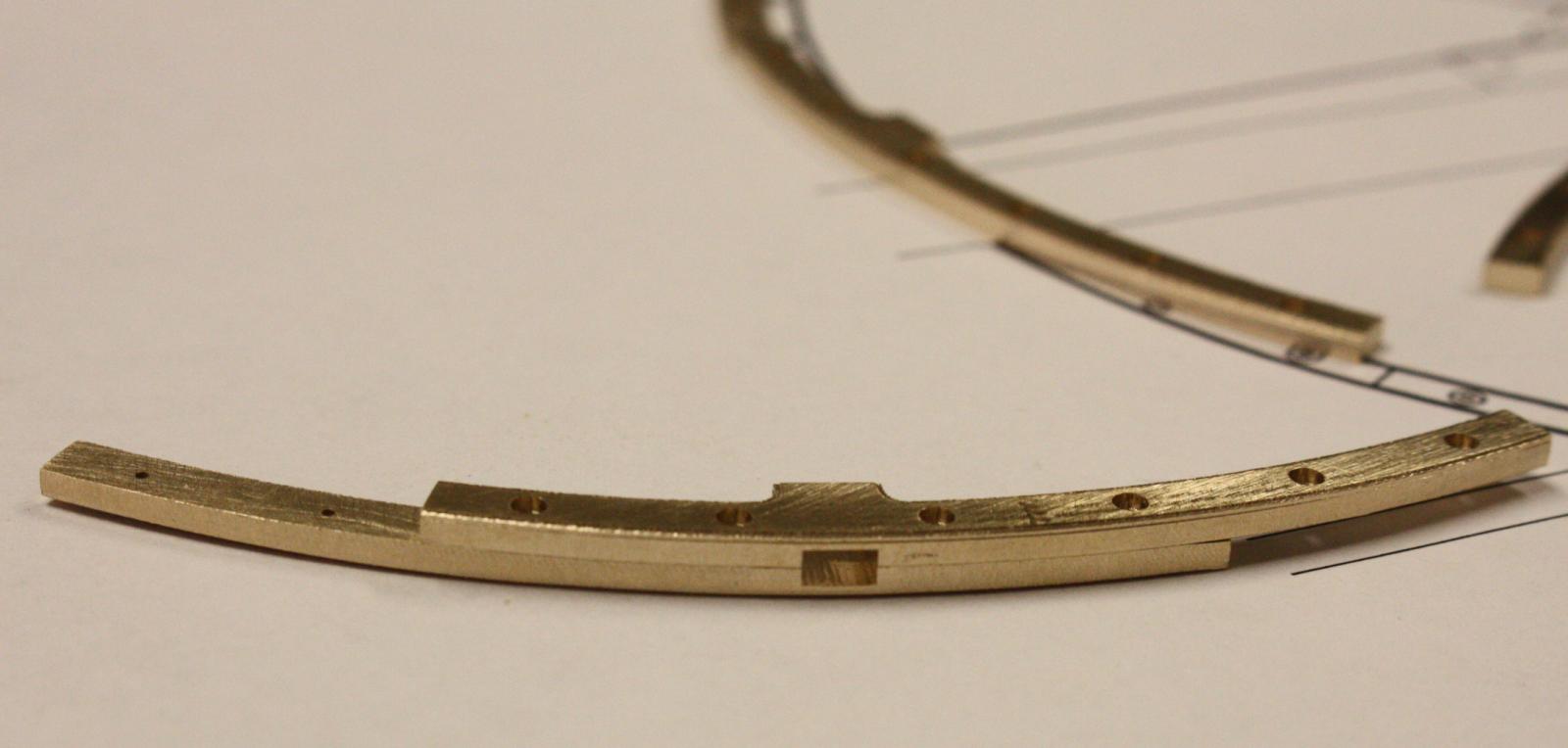
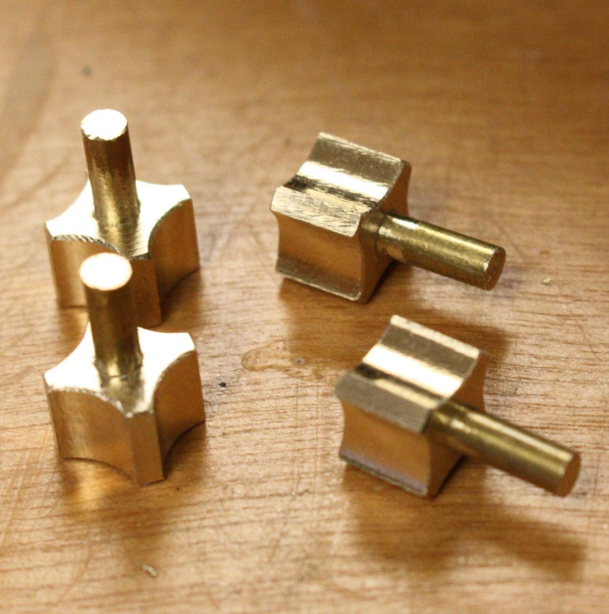
Some of the 64 flywheel rim sections.

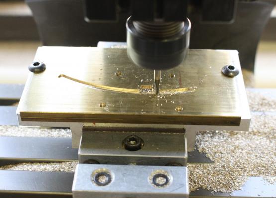
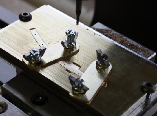
Jig for drilling the 384 holes in the rims. I'll have to re-make this in steel -- After only 8 rims, the hole is becoming distorted.
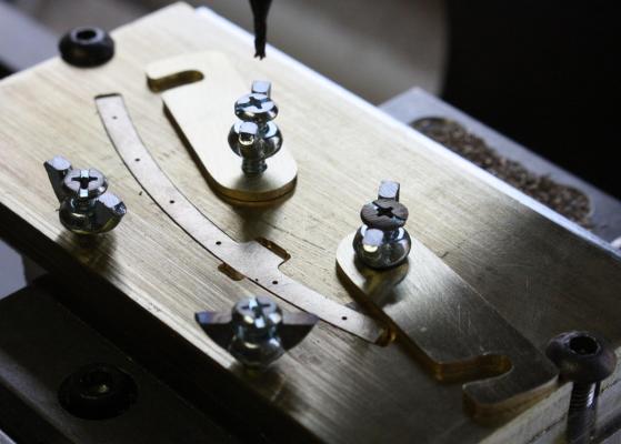
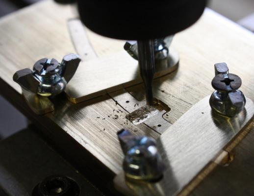
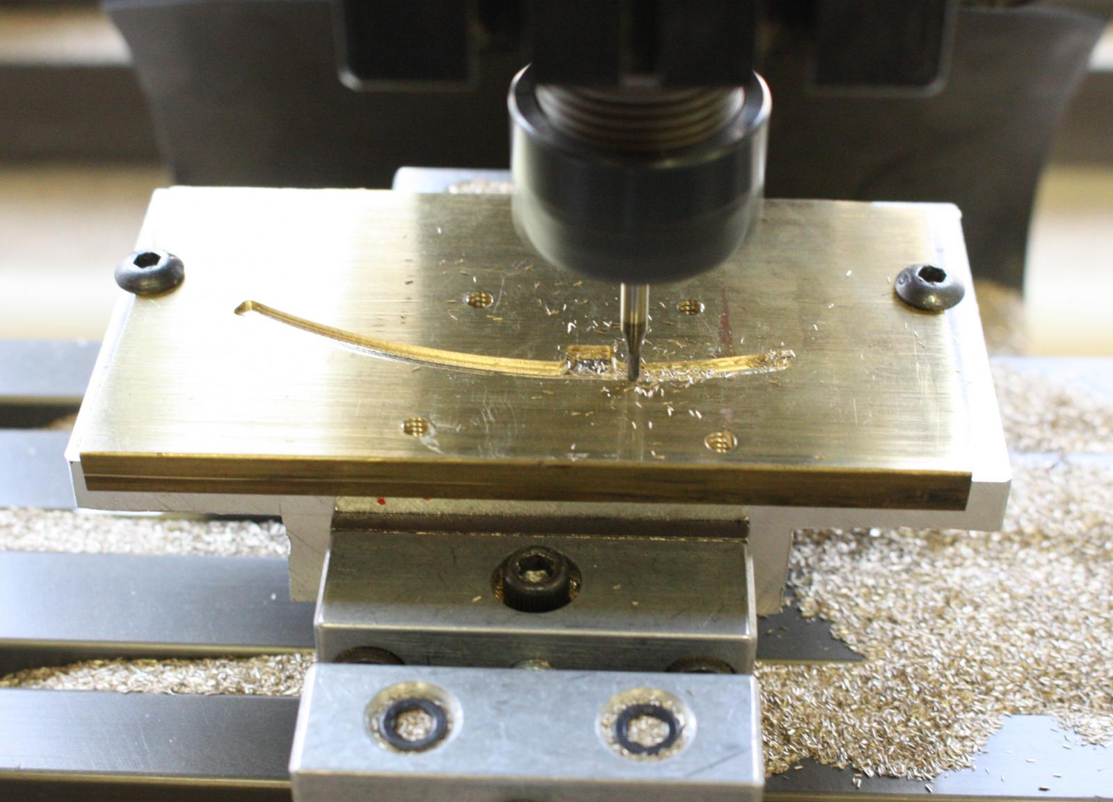
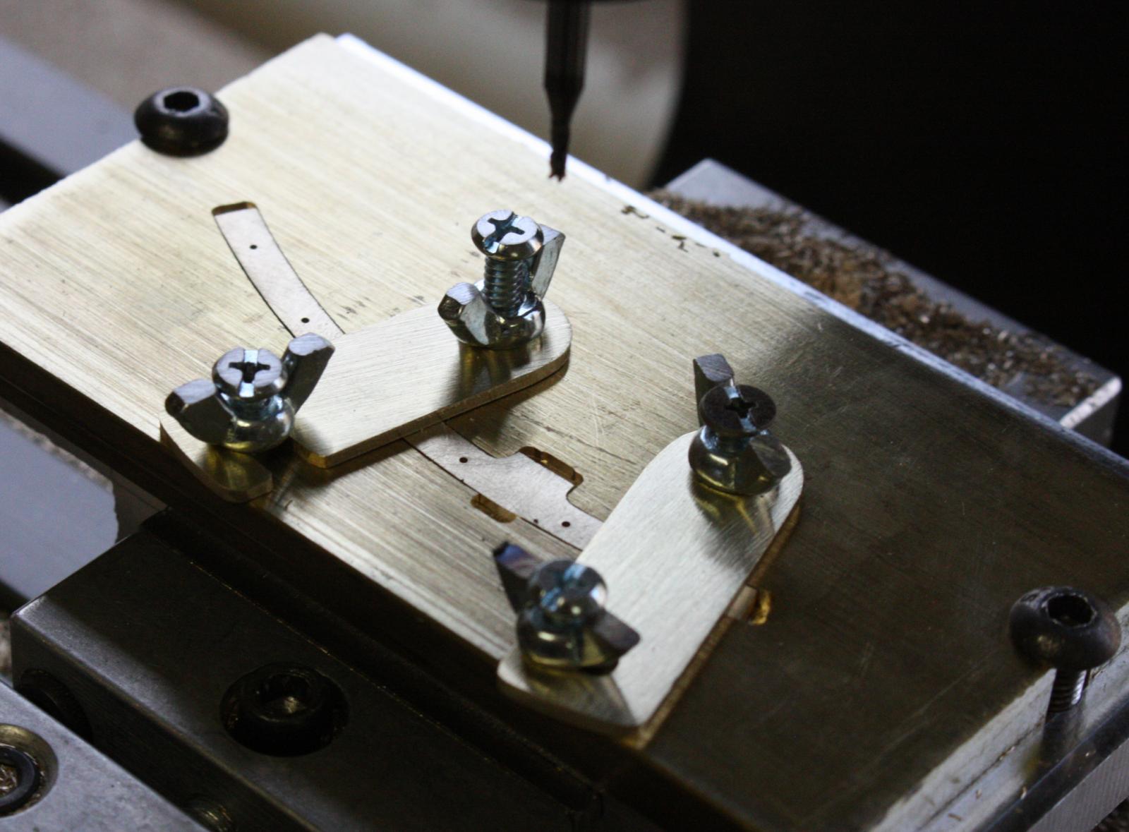
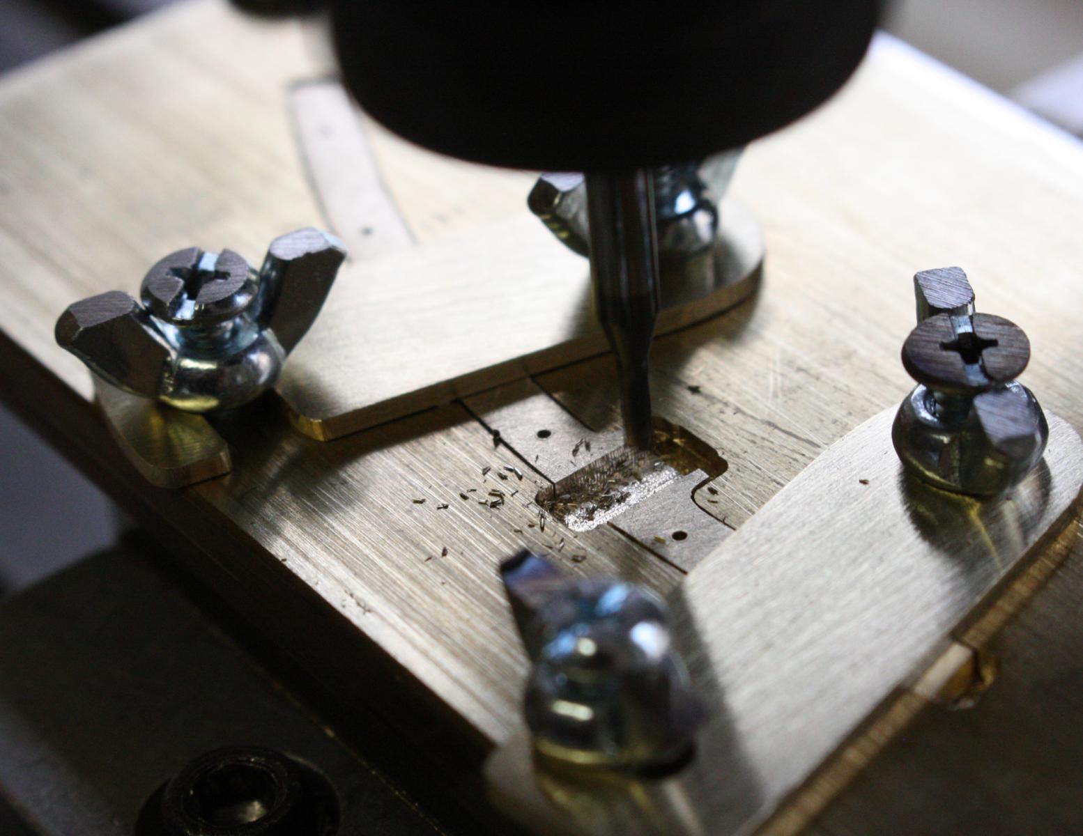
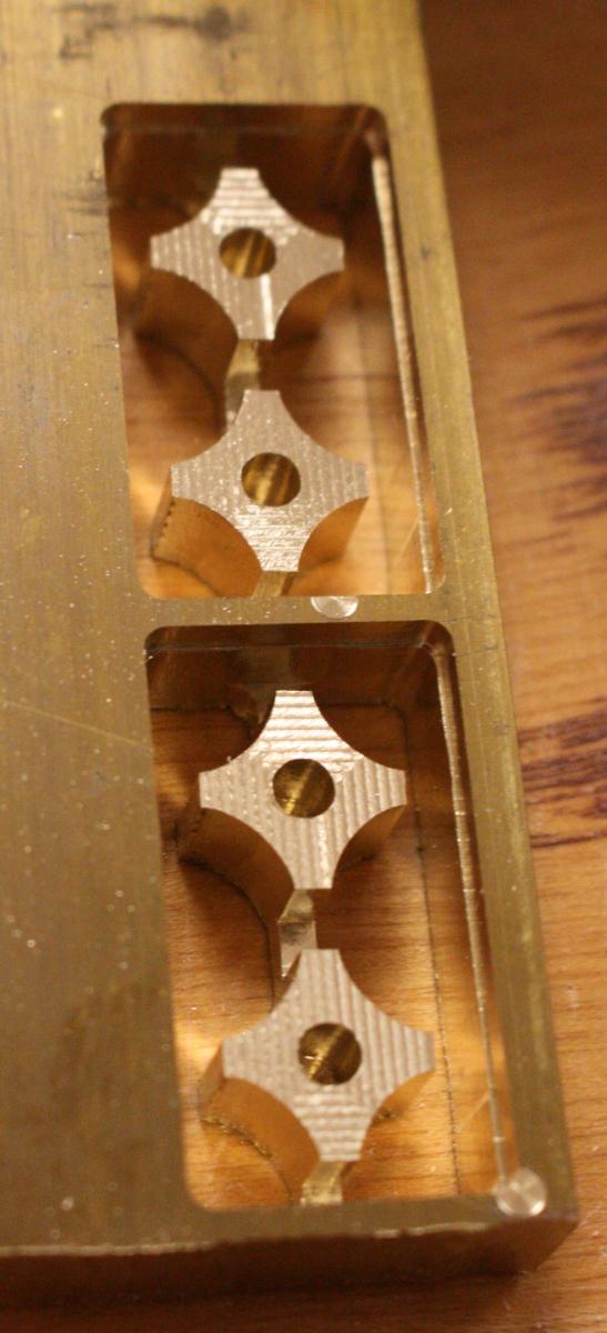
Milling a fixture to hold the rim sections in order to mill the pockets for the spokes. The original rims had dovetailed pockets and two wedges were driven into the spoke to expand it into the pocket.
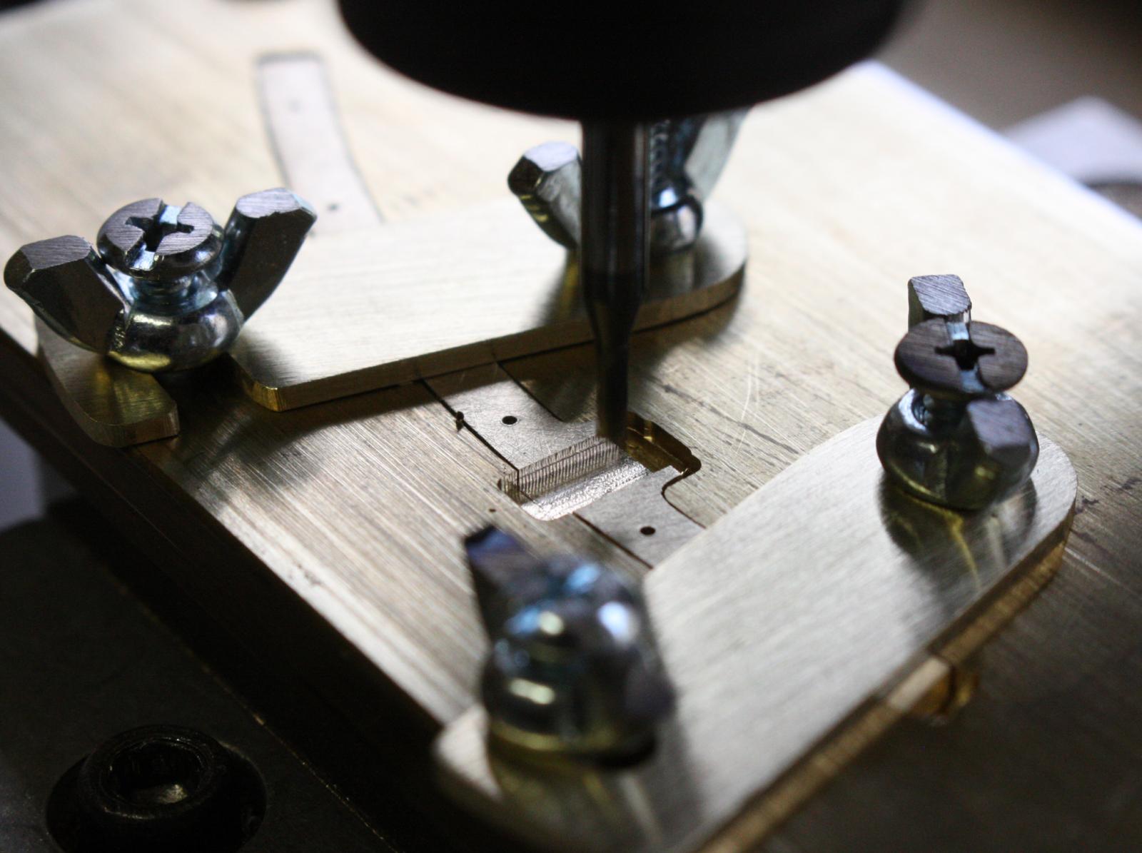
Fixture in use.

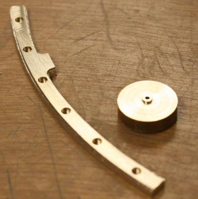
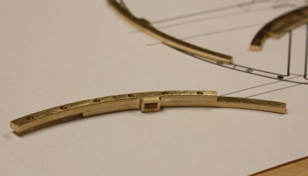
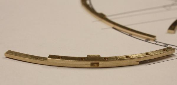
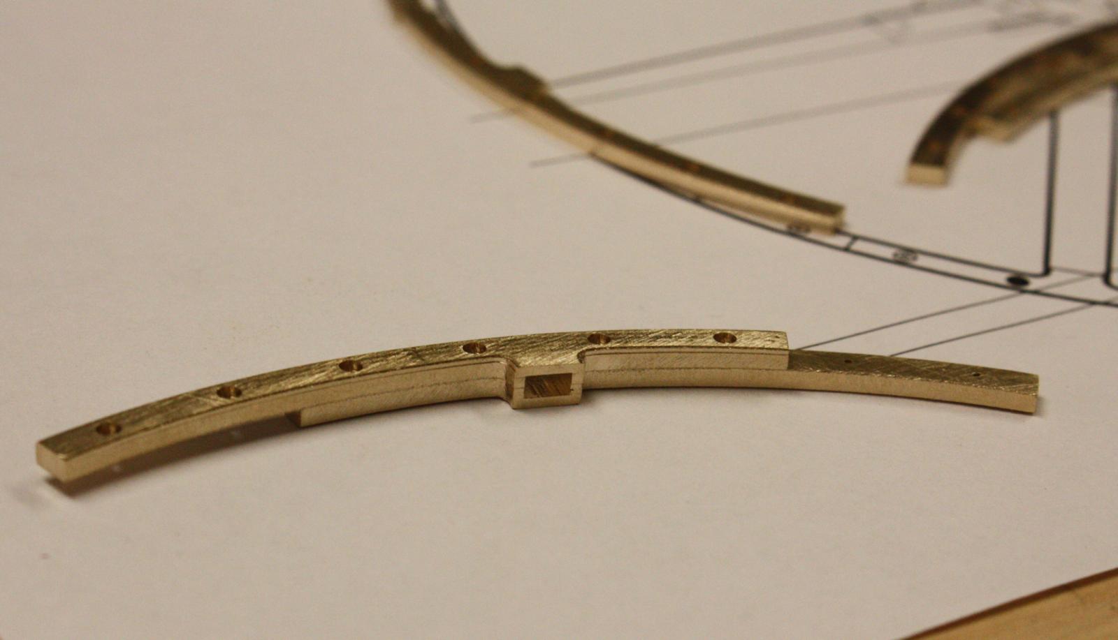
Completed pocket.
$50 dollars worth of brass and 21 hours of mill time doesn't look like much.
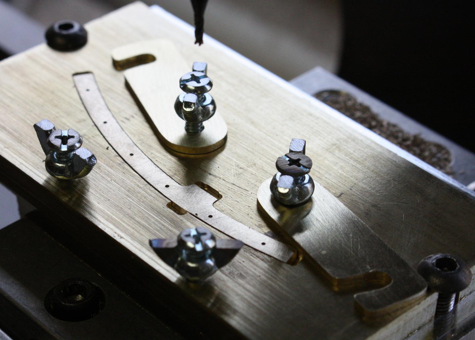
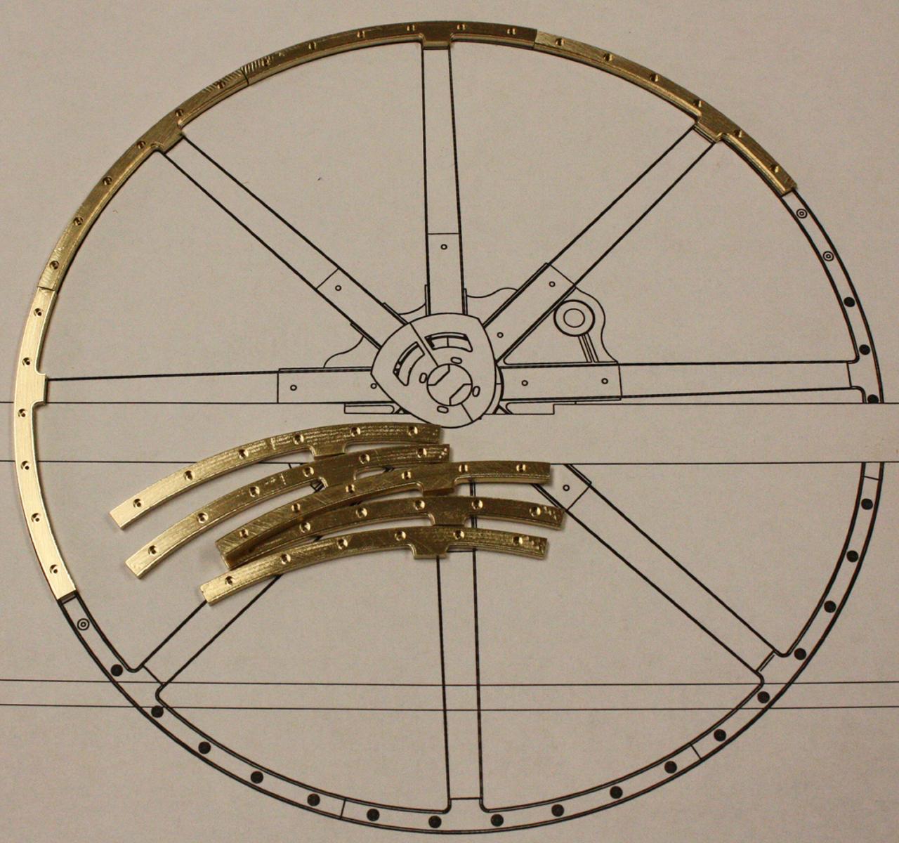
Since this is a waterline model, the bottoms of the flywheels will have to be cut off. To guarantee the alignment of the flywheels I printed out a pattern of each with the proper cut lines.
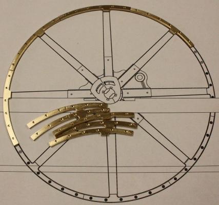
Test fit of one of the spokes.

- Wishmaster, hexnut, Omega1234 and 24 others
-
 27
27
-
-
Thanks Tom,
One is going to be displayed at the Oklahoma History Center, next to the remains of the original Heroine, the other will go to the newly opened museum at Fort Towson. Fort Towson was the original destination of Heroine and only a few miles from where she wrecked. They also have a collection of some of the artifacts from the wreck.
-
The deck is finally planked on the first model and I've started on the second. Another shipment of boxwood arrived and I hope I bought enough to finish this time.
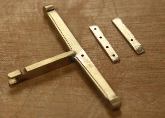
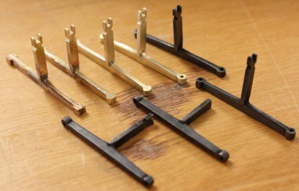
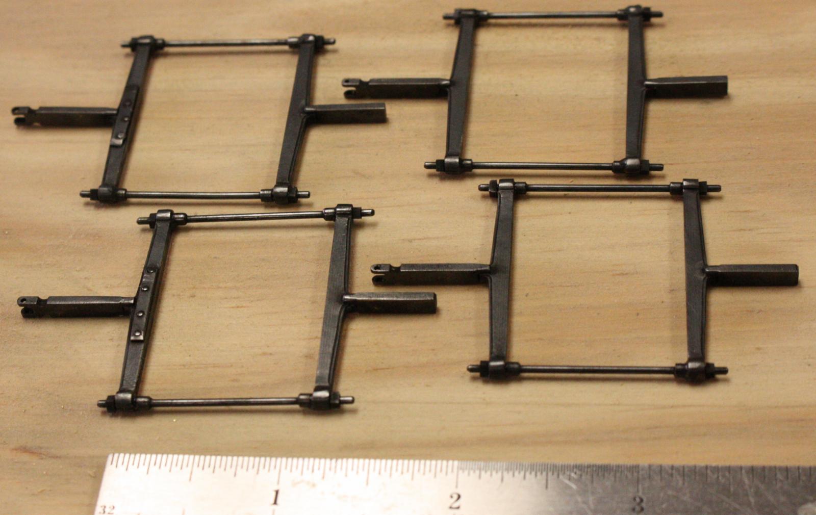
I did a little more work on the cam frames and started on the spokes for the flywheel.
Soldering the spreaders for the cam frames.

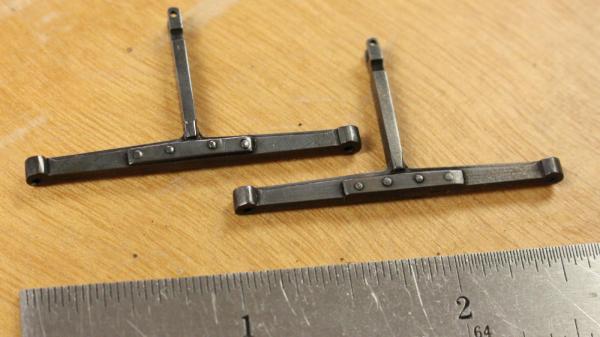
Completed cam frames. The cams were 24" X 24", the distance between the cam frames is 24 1/2"
Finally, one deck complete.

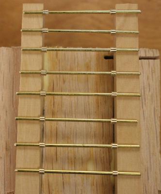
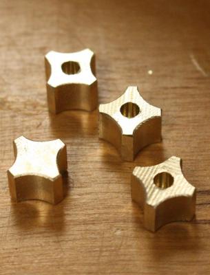
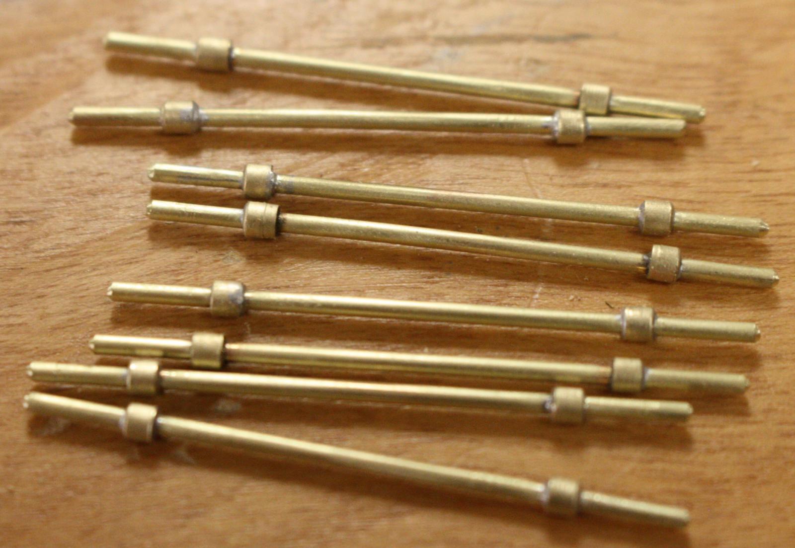
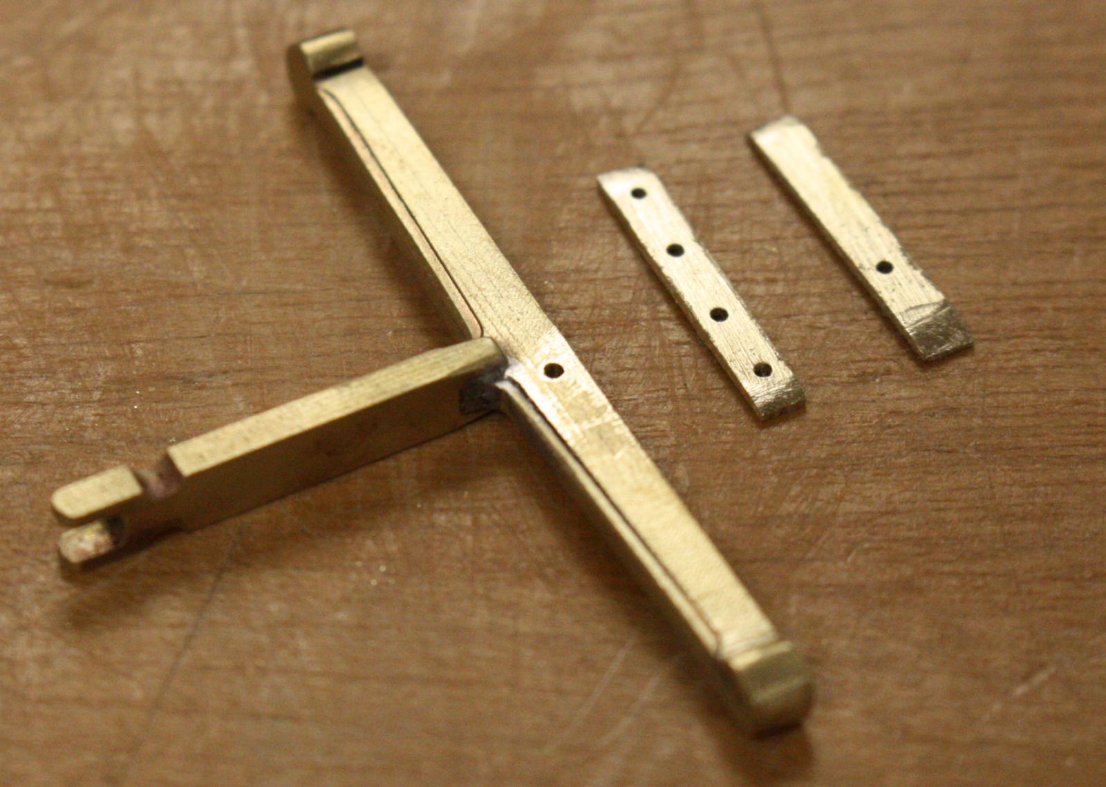
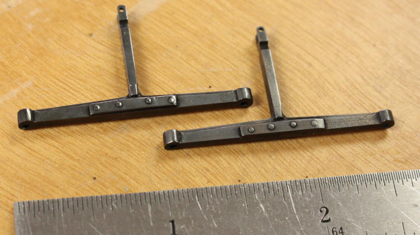
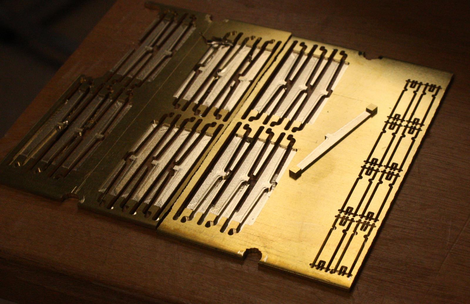
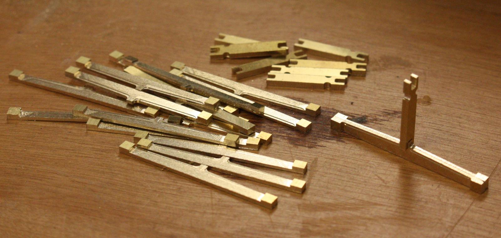
Flywheel spokes fresh from the mill. The channels for the spokes in the flanges were of different depths on the port and starboard sides requiring them to be cut slightly different.
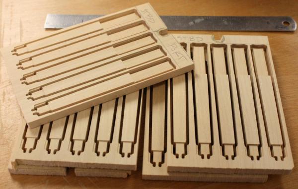
The outer face was beveled slightly from 5 inches at the flange to 4 inches at the rim. The mill could only cut one side so the bevel was added later.

Test fitting the spokes. The mill cuts the interfaces so cleanly that there is almost no hand fitting necessary. This will save a lot of time on the 96 paddlewheel spokes when I get to them.
-
Great idea Cathead, I know I'll find it very useful!
- Keith Simmons, Elijah, druxey and 3 others
-
6
-
-
Thanks David, Ed, and Frank,
This will eventually be part of one chapter in a book that Kevin Crisman's is currently working on. It will be a book on the archaeology of the western river steamboat with contributions from many of the students and researchers that conserved and studied the remains of Heroine. I will be contributing to the chapter on machinery but I'm realizing that there is still much to learn about what we have. This forum is turning out to be a big help and really making me rethink many of the things that I was previously assuming.
- dvm27, Cathead, avsjerome2003 and 6 others
-
9
-
Wow! I wish I had even half the manual machining abilities that you have. I sometimes feel a little guilty that I've relied so much on CNC over the years at the expense of my manual skills. There is definitely a quality to the hand made parts that you just can't get from CNC as your efforts prove! I can't wait to see what you make next!
-
-
Thanks everybody,
Greg, yes, unfortunately the webcam is down for good. The university has gone to a campus wide internet system and we no longer have our own server. Word is, it is very difficult to get permission to link up a web cam. Privacy issues I suppose.
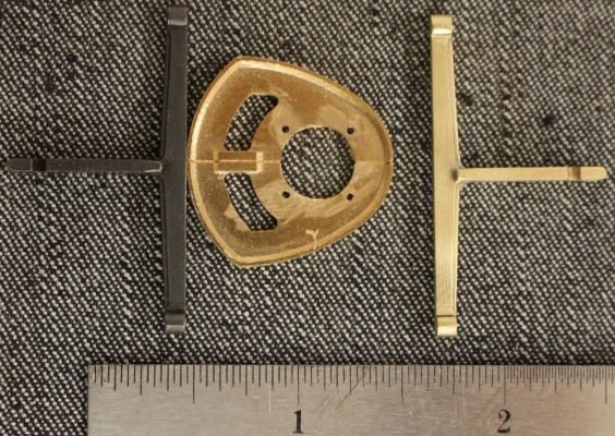
Cathead, no, the spokes don't line up. It is interesting that the hole for the crank pin is offset by the same amount in the same direction if you look at the face of the flange. I think the offset is 6.5 degrees if I remember correctly. The result is that the spokes are out of alignment by 13 degrees. Early on I wondered if it was possible that they were not a matched pair and possibly that they were both right hand or left hand flanges. The styles seem to be different as well -- the shape of the webbing between the spokes, the buttresses on the crank pin hub and the certain dimension don't seem to be consistent between the two.
-
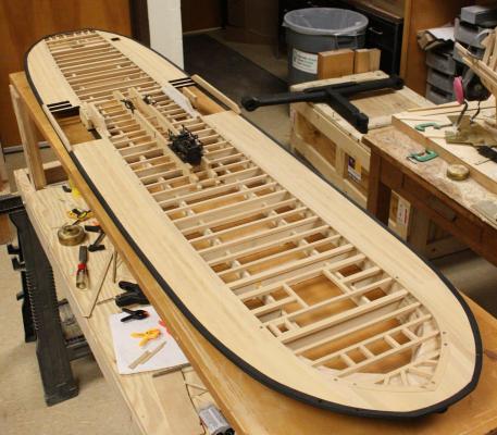
I finally finished planking one side of the deck but, I'm running low on wood. I have a new shipment coming in this next week that should be enough to finish the two models.
I decided that I am going to include the repaired cam frame in the model. This vessel was in such bad shape at the end and there is a possibility that other cam frames were also repaired.
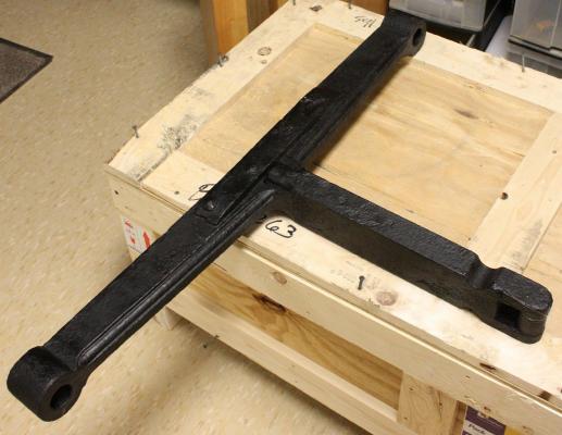
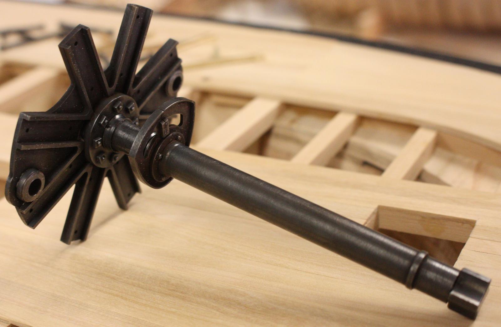
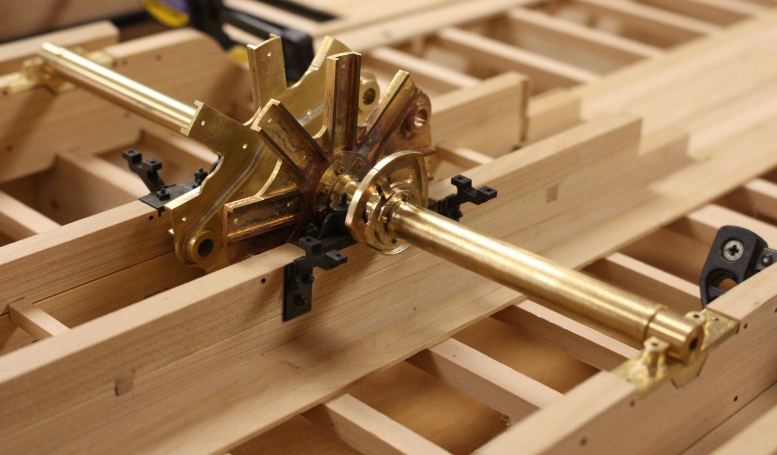
Progress on the flywheel flanges and shafts.


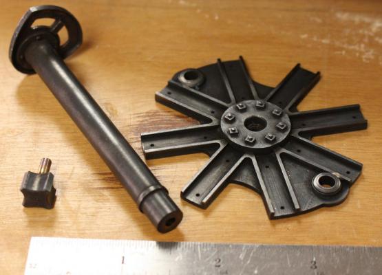
Completed port flywheel flange and shaft.
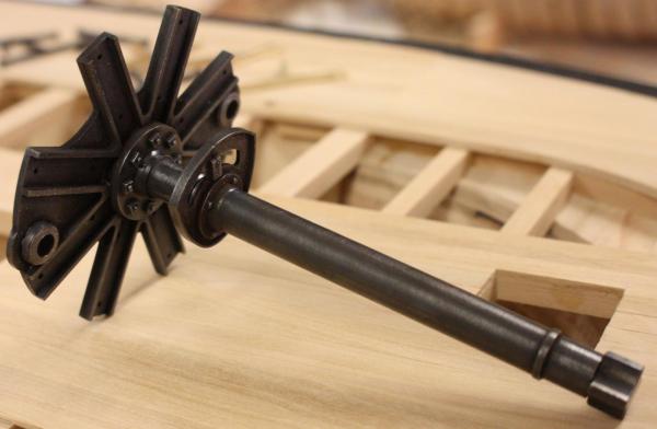
Completed starboard flywheel flange and shaft.

Kevin and I have been discussing the boiler arrangement and we came up with some good information. In Kevin's research, he came up with several examples of early sidewheelers with 4 or more boilers. Although many writers mention that Yellowstone had only 3 boilers, her original contract called for 4 boilers 36 inches in diameter and sixteen feet long. Yellowstone's engine and flywheel shafts were identical in size to Heroine's. The important piece of information that I had been overlooking is that many early boilers only had a single large flue. At the end of the 1830s, most boilers were being constructed with the more efficient two flue configuration. With similar dimensions and approximately the same date, there is a good chance that Heroine had the same 4 boiler arrangement that was planned for Yellowstone. If she had single flue boilers, she most likely would have had 4, if she had two flues, there is a better chance that she only had two or three.
- hexnut, michael mott, Mirabell61 and 23 others
-
26
-
-
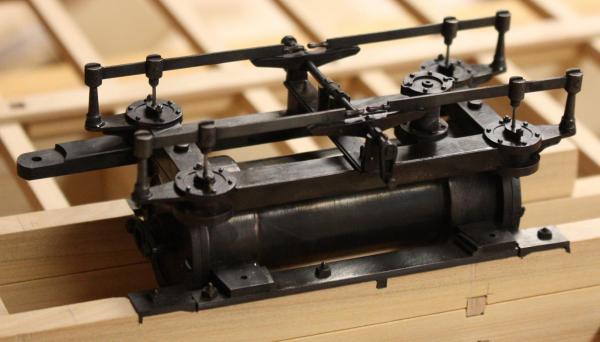
The deck planking is slowly going in. It's amazing how many 4 inch wide planks it takes to cover a significant part of the deck. Between strakes, I finally had a chance to get back to the machinery. I was able to finish the cam frames and start on the flywheel shafts.
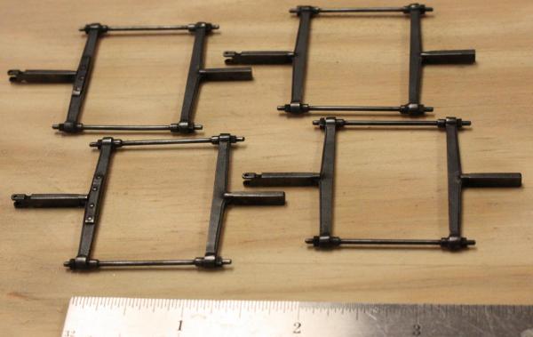
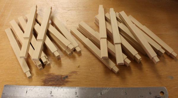
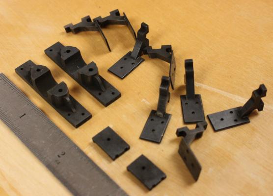
Cam frame parts fresh from the mill.

The five frames in the back show the steps in shaping and finishing the cam frame. The middle frame on the bottom row has the pivot cut off. The aft frames are not connected to the valves so it is not needed. I have been debating on whether to include the repair on one of the frames. Since it was found in the hold as a spare, It wouldn't be accurate to include it with the working machinery. On the other hand, it is a good example of the extensive repairs on the vessel.
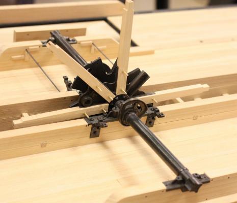
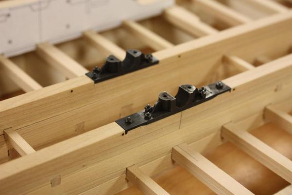
Cam frames as they would have been positioned in relation to the cam. The stroke of this cam and cam frame was 6 inches.
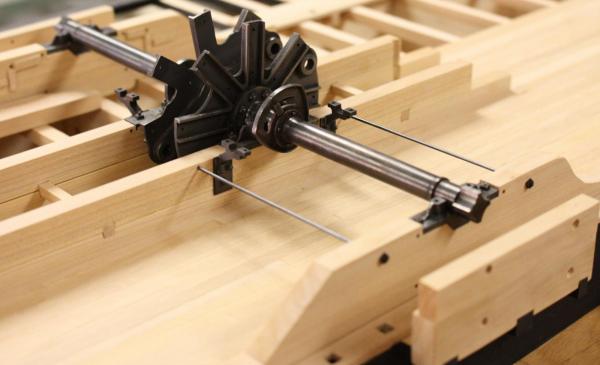
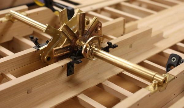
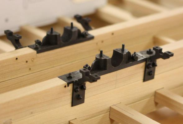
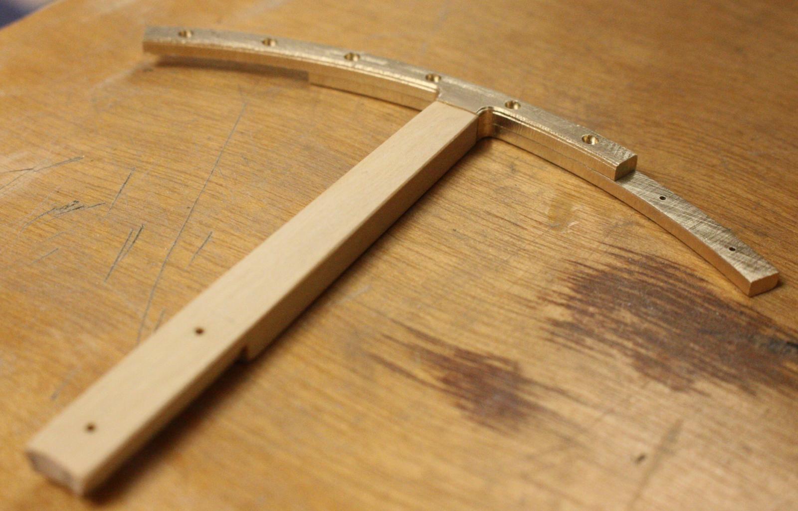
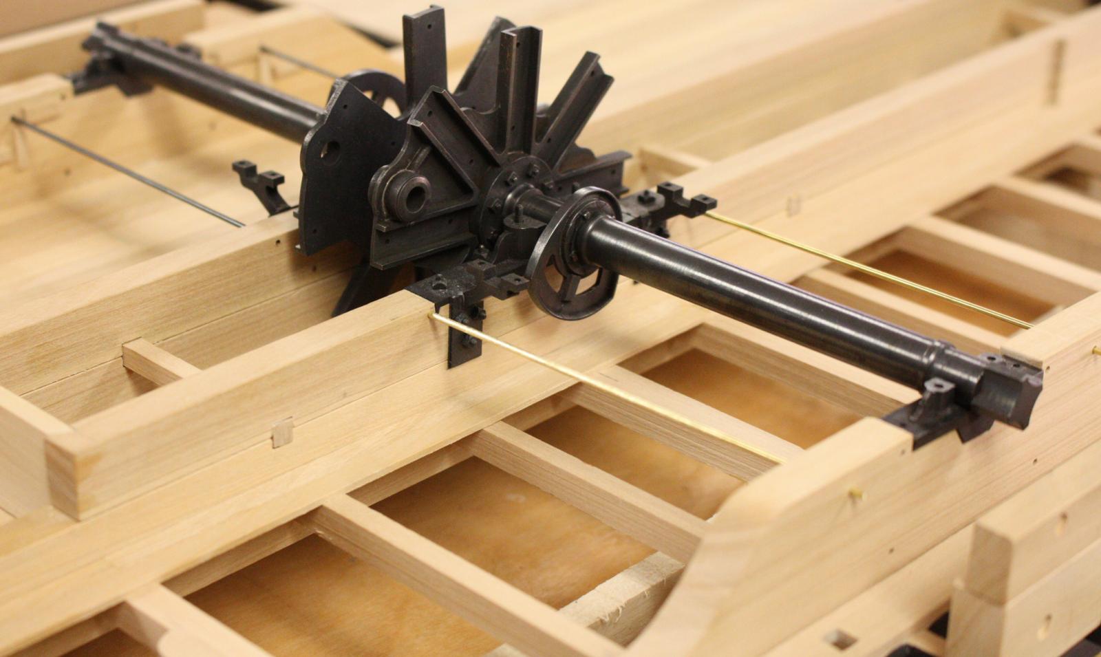
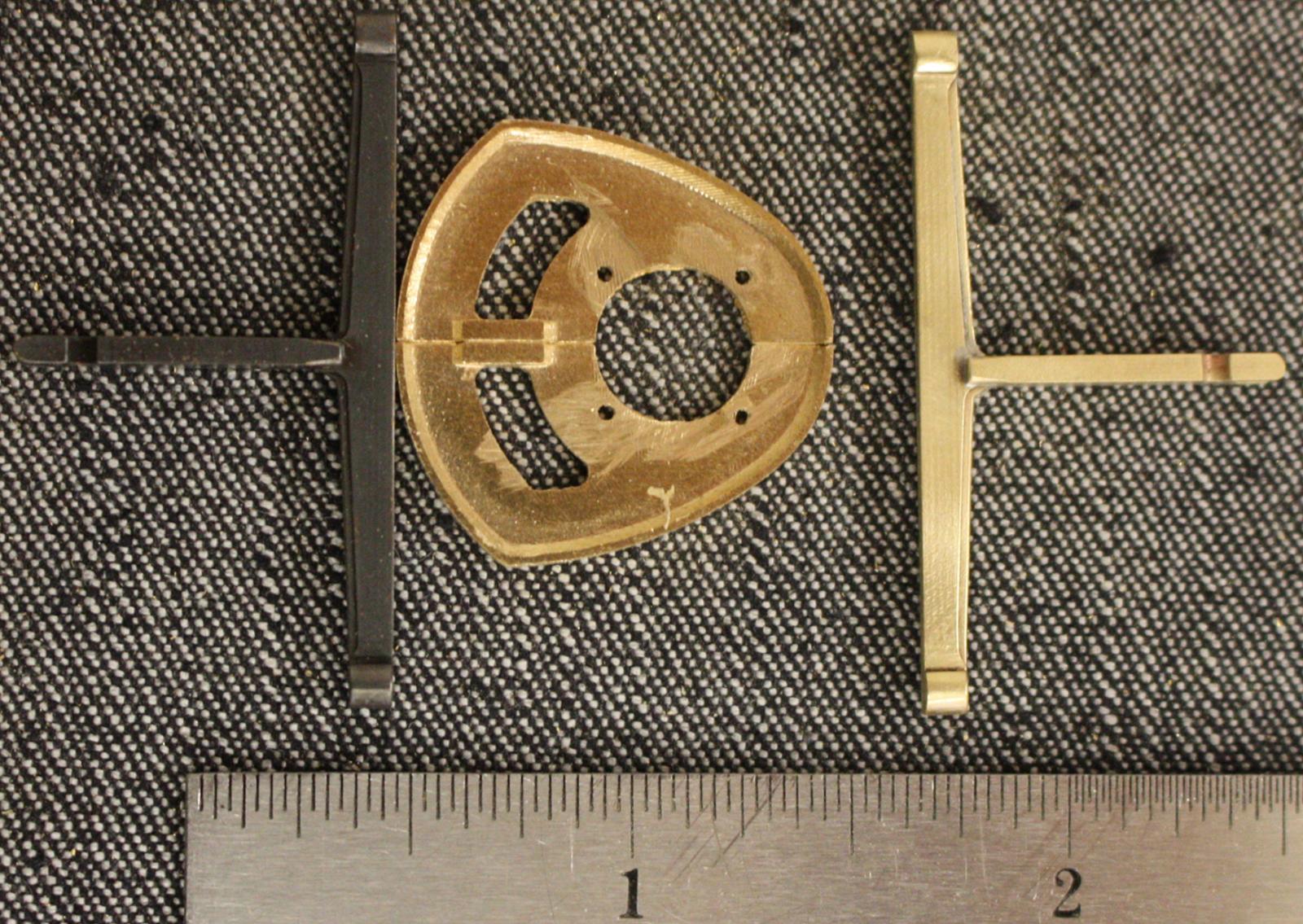
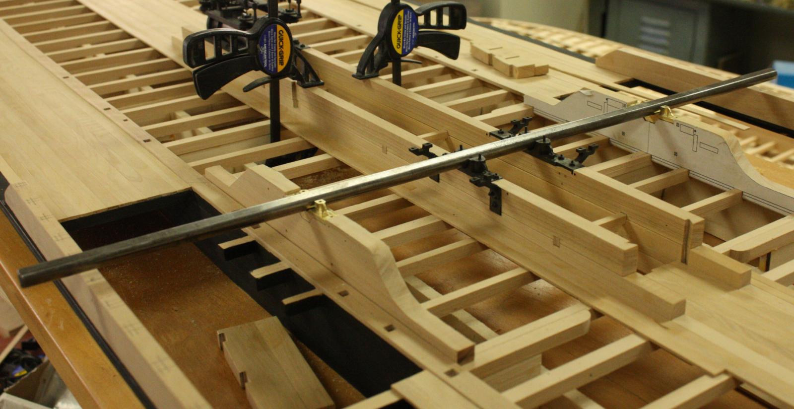
Using a beam from a beam compass to align the two outboard flywheel shafts.

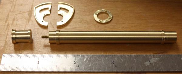
Pieces of the flywheel shaft. On the original, the flange for the cam was cast in place. In order to include the fake bolt heads, I had to machine it separately and slip it onto the shaft. This also required that I turn the shaft in two pieces.
Shafts in their bearings with flywheel flanges attached.
-
Hello druxey, Cathead, and Bob,
It's good to hear from you again and I wish you the best for the New Year!
Druxey, I was trying to come up for a term for the splint on the cam frame. I have to admit I had to google the word kludge -- you nailed it. It is a term that I will have to add to my vocabulary when speaking of Heroine. I think the term can accurately be applied to just about every repair on Heroine. Heroine is a tribute to the ingenuity of her crew but I have no idea how she continued to operate with many of the repairs.
Cathead, The hull planking was fastened with round headed spikes with about 3/4 inch heads. The deck planking was fastened with large nails, two per plank per beam. I have some wonderful drawings showing the locations of all the deck nails but have yet to find info on the size or shape of the heads. Kevin will be returning from a conference on Monday and I'll get that info from him. As to how I am going to simulate it, I'm still not sure. If the heads were large enough, I'll probably use brass wire. Looking at a large section of deck that was recovered from the wreck, the nails are almost invisible from a few feet away so I wouldn't want them to be too obvious. I think I am going to use a darker wash on the exposed wood to give it an aged look and I was toying with the idea of using a pin or fine punch to simulate the nail heads. The wash would make the pattern stand out.
-
Hello,
I hope everyone had a great New Years! I spent the last week playing catch-up after taking some time off with the family.
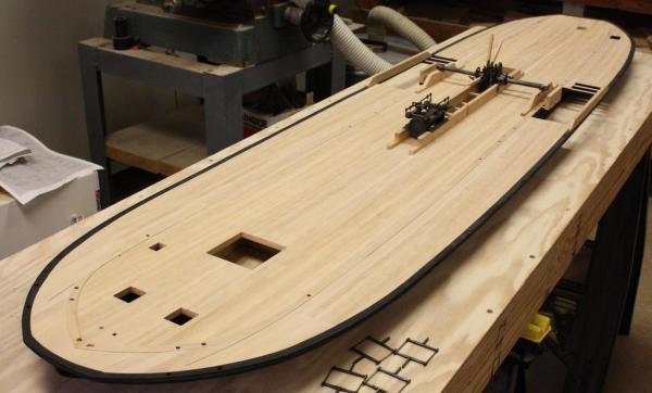
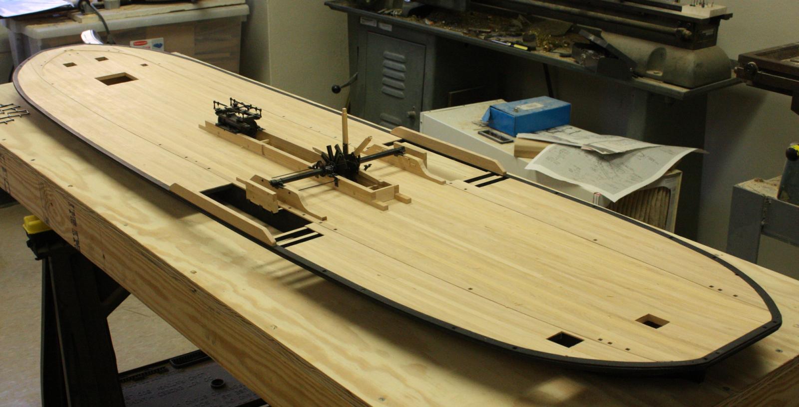
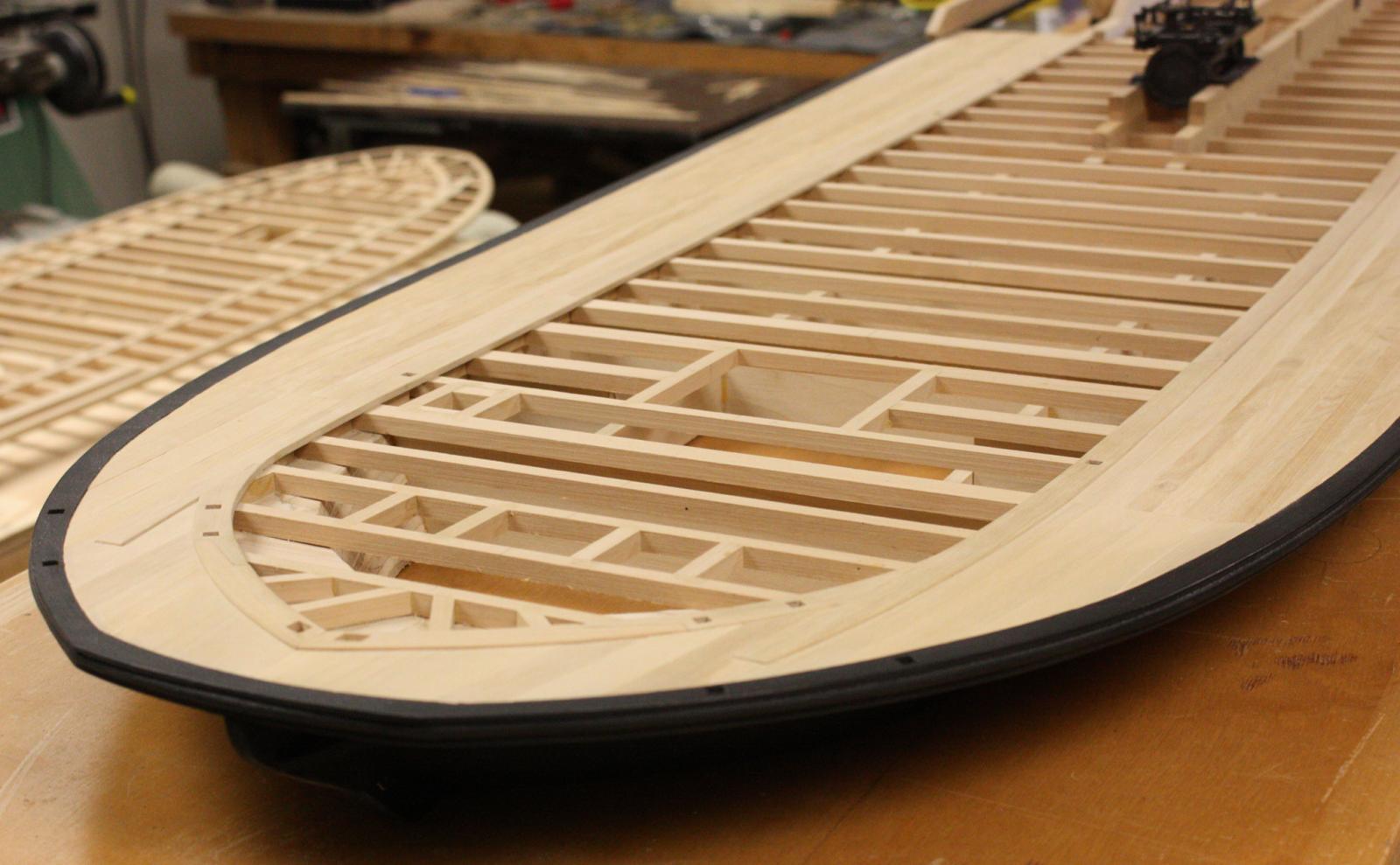
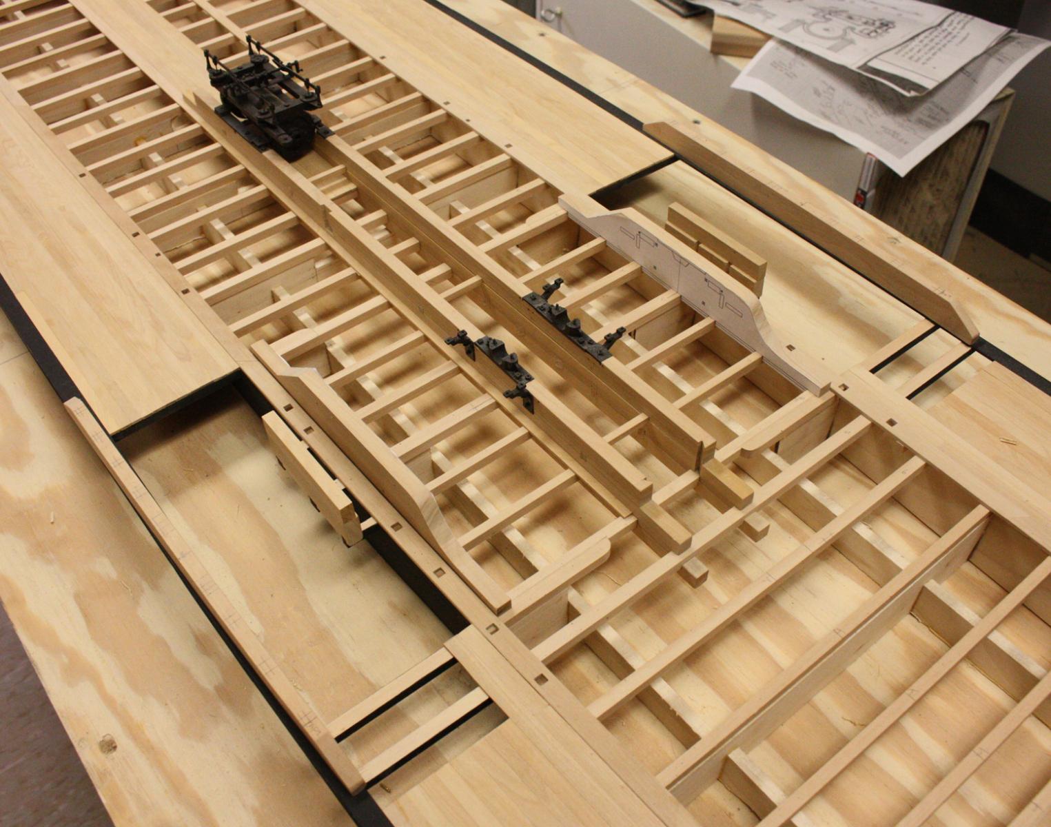
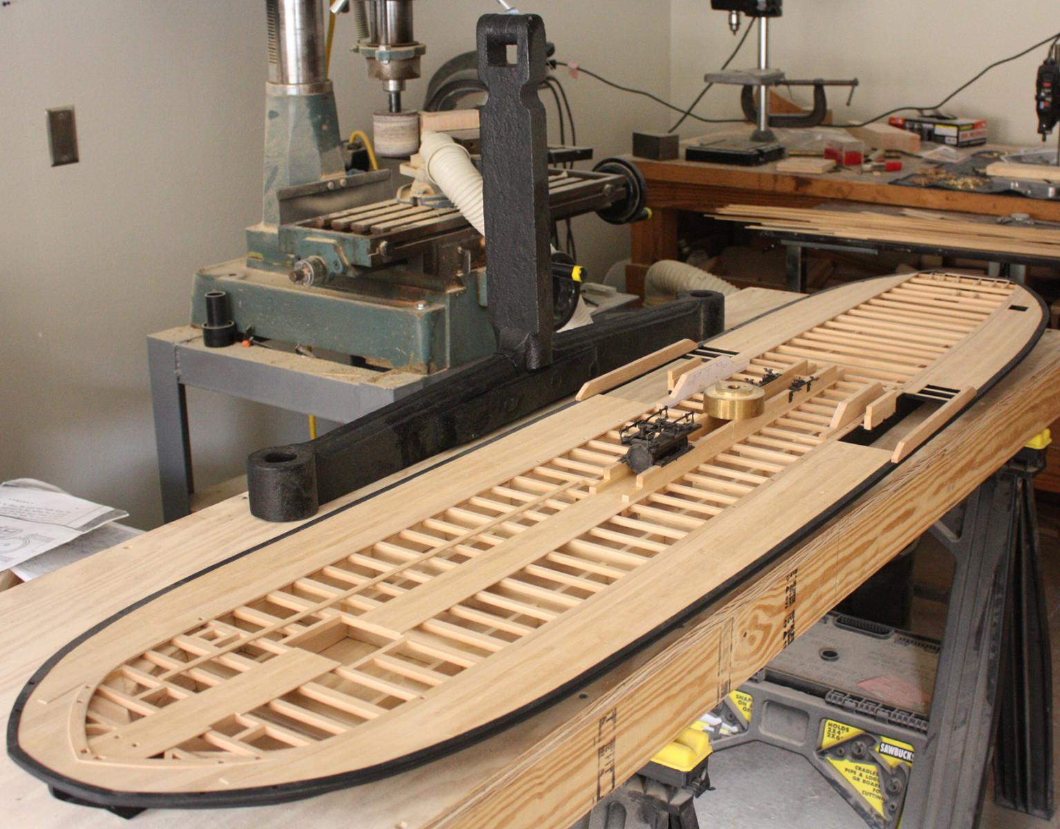
The rest of the machinery requires some of the deck to be in place so that took up most of my time this last week. Heroine's planking isn't pretty! The widths of her planking range from 3" up to 15" and there is very little pattern to it. In the stern, the port side planking ranges from 6 to 10 inches and the corresponding area to starboard is made up of 3 to 6 inch planking. Although some of it is repairs, some of it looks like they ran out of the wide planks quickly and made due with whatever they had.
Guard planking completed. Kevin discovered the remains of black paint on the hull timbers and the guard cap. He believes the Upper works were white with black trim.
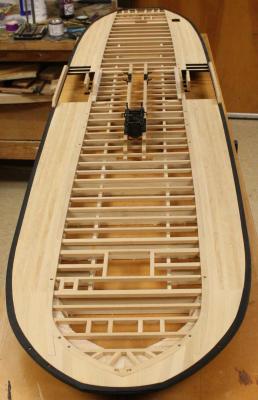


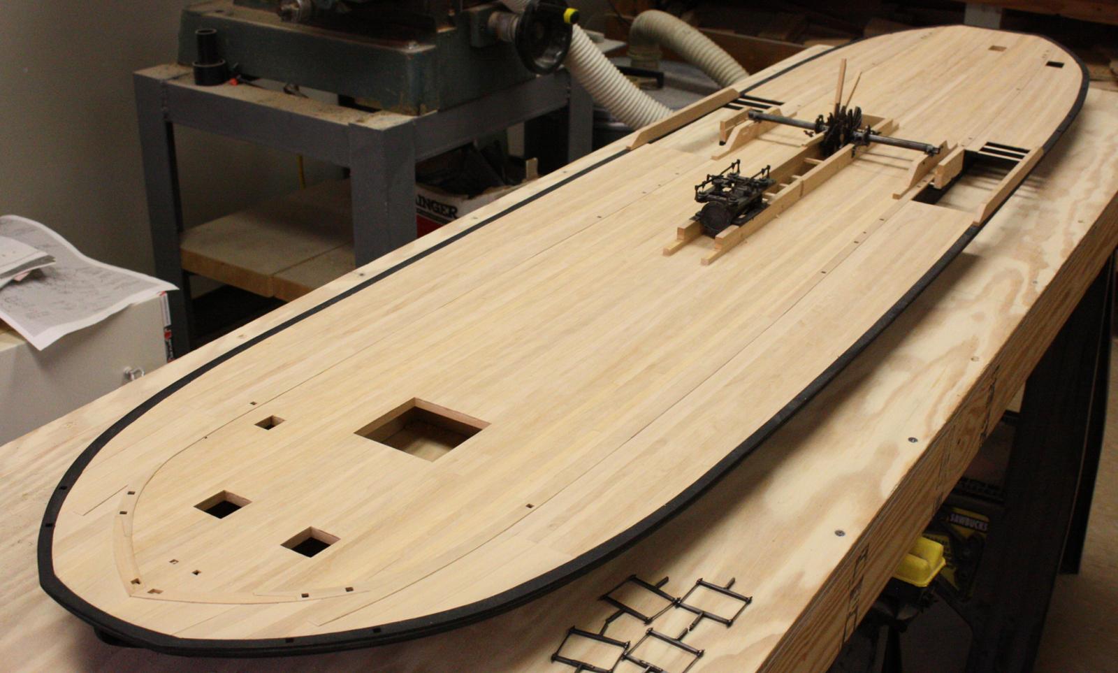
Starting to add deck planking. One of Heroine's cam frames in back for scale.

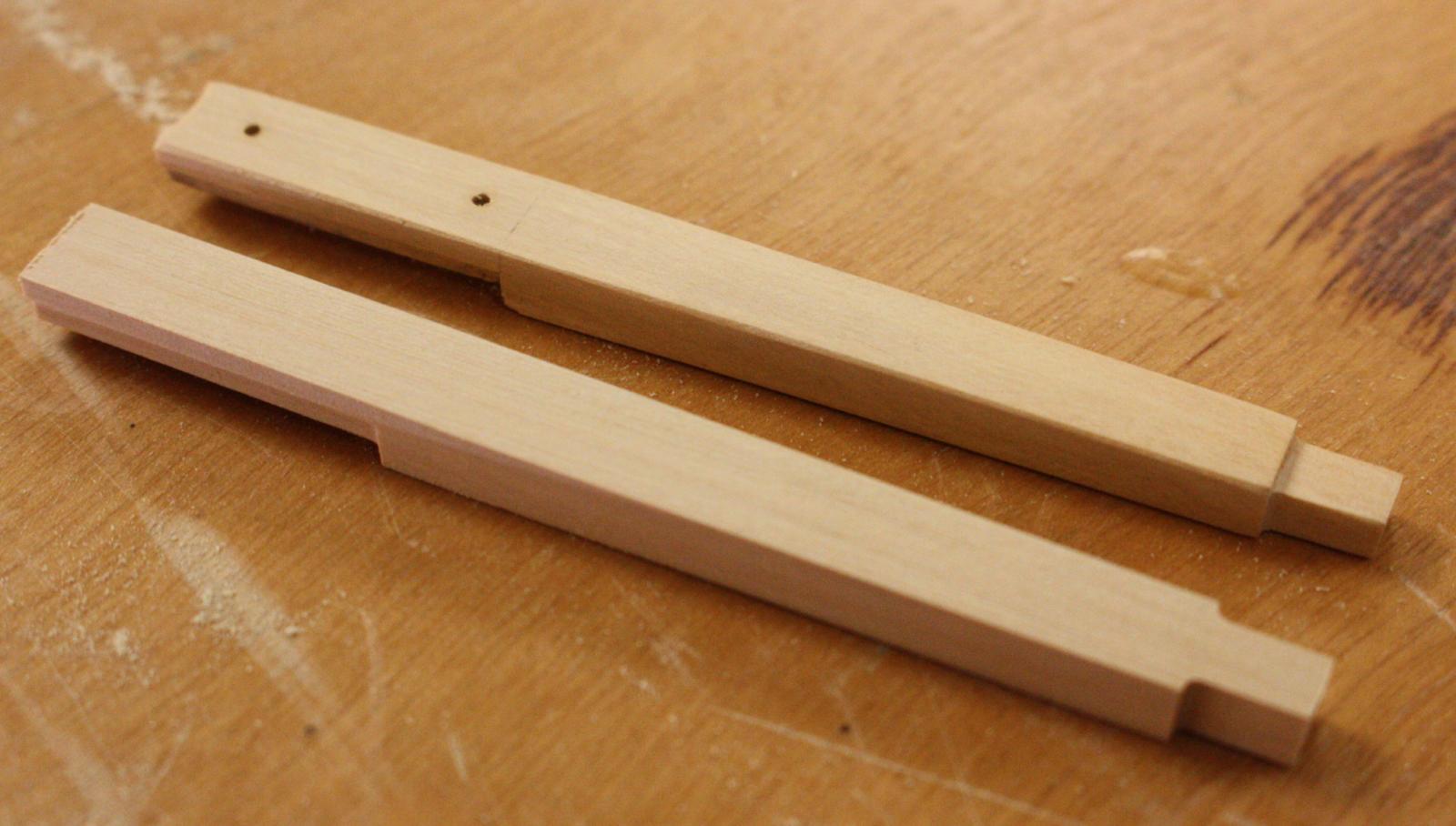
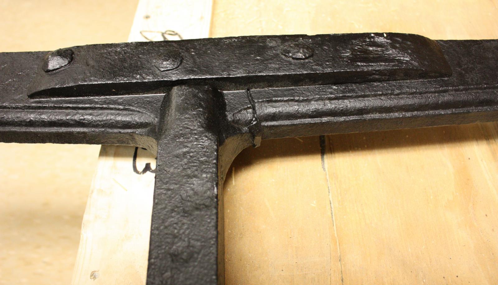
This cam frame was in the bow compartment as a spare. It was late coming out of conservation and I haven't had time to model it in AutoCAD for machining. That will be my first task for next week.
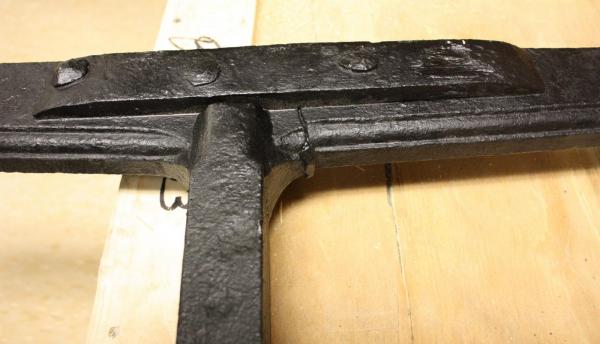
Close up of repair to cam frame.
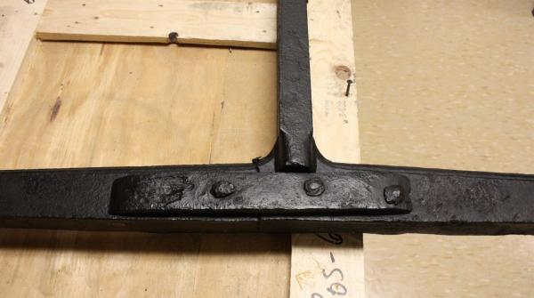
Close up of wedge in one arm of the cam frame. It appears that when the splint was riveted to the frame there was still some play so they drove this wedge in.
-
Thanks Tom,
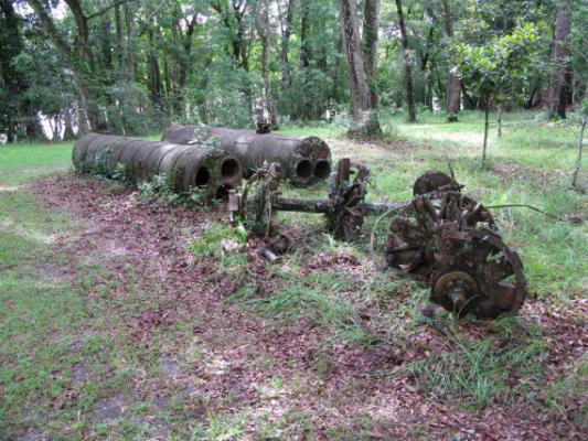
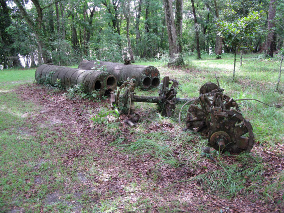
Merry Christmas to you and everyone else that has been following and contributing. I'm sorry that I haven't been more involved, the holidays have kept me away from the computer and I will be away for the better part of this next week. I just wanted to thank everyone for the info and I am really looking forward to getting back into the lab next week to work on the flywheels and paddlewheels. Yes Keith and avsjerome2003, the Cairo was of interest to me and I copied the safety vavles for Heroine but as you point out, it must have put out a lot of power. I haven't had a chance to discuss it with Kevin but, I'm now leaning toward two boilers for Heroine. The attached photo is from Ft. Gadsen in Florida. The Paddlewheel flanges in the photo are almost exactly what we recovered from the Heroine. The drive train seems comparable to Heroines except for the lack of a flywheel and throw-out bearings. The vessel was a sidewheeler with paddlewheels approximately the size of Heroine's. I think this might be good evidence that Heroine only had two.
I hope everyone has a wonderful New Year!
Glenn
-
Hello everybody,
I left town this morning to visit the in-laws and just got home to find all this good info. First of all, thank you Cathead for mentioning the correct diameter of the cylinders as 34". In autoCAD I work with radii instead of diameters. I was thinking 2 x 17" is 34" but typed 37" by mistake in an earlier post. Secondly, I'm coming around to the idea of fewer boilers. I think the most convincing evidence as Cathead pointed out is that we only have one engine. As druxey pointed out, we have very little to work with and in a way, that gives me a little freedom. I agree that four boilers seems extreme and I' m leaning toward just two. Fortunately, the drive train is well represented and will take me some time to complete so I have some time to look for more evidence and discuss it with Kevin before committing to anything. I want to thank you Cathead for bringing this up and possibly preventing me from making a pretty big mistake.
- mtaylor, Dimitris71, avsjerome2003 and 4 others
-
7
-
-
Cathead, this was just the exchange I was hoping for! As you know, there is so little info out there on the actual construction on these structures. We have almost the whole drive train of the heroine's engine and have enough dimensions to put together a convincing reconstruction of the engine itself but after that we're tying to make accurate guesses. If you don't mind, I could really use your input. I hope you don't mind me stealing some ideas from you on the upper works.
Mark, yes the boilers and engine were probably salvaged shortly after running onto the snag. Fortunately, we have one sole plate from the engine giving us the footprint And maximum diameter of the engine. From the flywheel, we know the stroke was exactly 57 inches. The one recovered full stroke cam tells us it used poppet valves and had a valve stroke of 6 inches. we also have the height of the cross head slide in relation to the footprint of the cylinder. Working out the geometry was pretty straightforward. I just wish we had more on the boilers.
-
Hello Cathead,
Thank you for the information. We are not sure if she did have four boilers. It was an early assumption that Kevin made and I'm don't remember what the justification for it was. Comparing the vessel to Bertrand, l'm wondering if we might have had only two. I will see Kevin this next week and discuss it with him. I sure would be happier building only 2. As for the water pump, there is a 9 inch wide notch cut in the cylinder timbers at the forward end of the cross head slide. We are certain that this supported the lever for the feed water pump. Working off of a linkage to the cross head, the lever would have operated a low pressure pump that pumped water to the preheated shroud around the steam exhaust and a second high pressure pump that transferred the water from the shroud to the boiler. I have drawings of the arrangement but unfortunately they are at the office. I'll try to post them early next week.
- Dimitris71, Cathead, rek and 5 others
-
8
-
You got that right druxey! We're pretty sure about the diameter of the boilers from the radii on the top of the standpipes and one opening in the firefront. The length of the gratings give us an idea about the firebox. We have a radius for the top of the firebox doors. Everything else is pulled together from bits and pieces of the remains of contemporary boilers. I think it is a reasonable reconstruction but I'm open to new ideas.
-
Thanks Michael,
I'm learning a lot from this build. I have already changed a couple of details on the model thanks to previous comments and questions. It nice to have access to the broader knowledge base that this site provides.
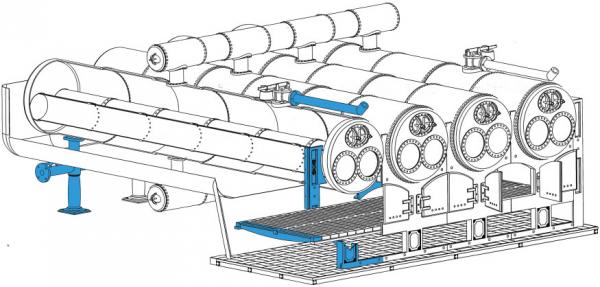
Building the boilers is coming up soon and we only have a handful of pieces from Heroine's boilers. Three pieces of the firefront, a few gratings the steam exhaust from the safety valve, one standpipe and a checkvalve just before the standpipe. I've done a preliminary reconstruction showing the surviving features in blue but, many details are still missing. I look forward to any comments or criticisms.
- wyz, Mike Y, michael mott and 9 others
-
12
-
Thanks so much to everyone for your kind words. I'm sorry for not being able to respond more quickly. I have a six year old and a nine year old that demand my attention as soon as I get home from work and when they are not demanding my attention they are hogging my iPad to play my little pony.
Thanks Greg, for the engine I used five dips in Birchwood casey's brass black. I let it sit for about twenty seconds and then rinse and swab with a q-tip between dips. I let it dry over night and then rub it all down with a rag slightly dampened with oil. The oil does a nice job of evening everything out.
Hello S. Coleman, good question about dropping the fire. I had never heard of it being done on a western river steamboat. I'm had to look up the process for locomotives. If I understand correctly, the gratings were removed and the coal in the firebox is dropped directly onto the tracks to reduce the heat. On heroine, the gratings were removable but only a couple would be accessible with fire in the firebox. They would have only been able to drop the fire into the ash pit but I'm not sure if it would have provided much reduction in heat. Coal provided a much more intense heat than the wood that heroine was using and quickly dumping the fuel would have provided a greater degree of heat reduction. Now I'm really curious if steamboats had a comparable process. Maybe someone else out there has an idea.
- dvm27, Dimitris71, mtaylor and 4 others
-
7
-
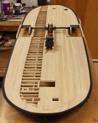
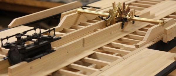
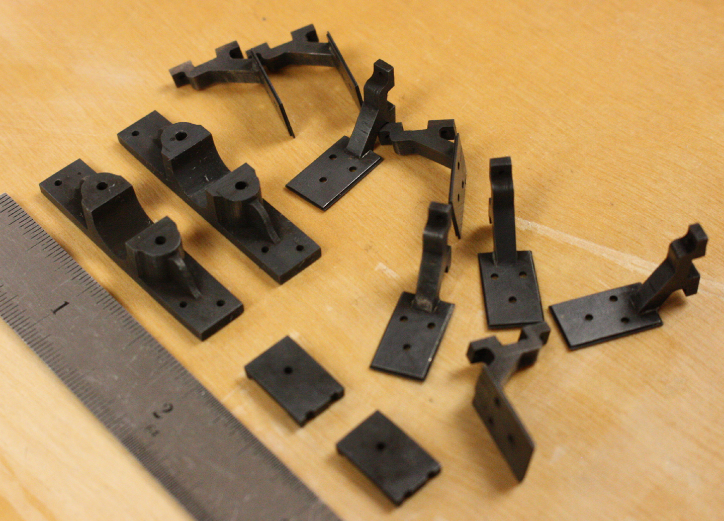
I was almost able to complete the engine this week. All that remains are the throttle handle and feewater preheater on the exhaust. I fitted the flywheel bearings and the cam frame supports. The next step will be position the remaining six bearings in-line with the flywheel bearings. I'm planning on using a round beam from a beam compass and sleeves turned to the proper journal diameters to guarentee alignment.
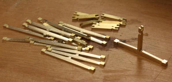
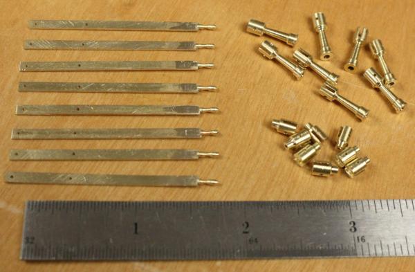
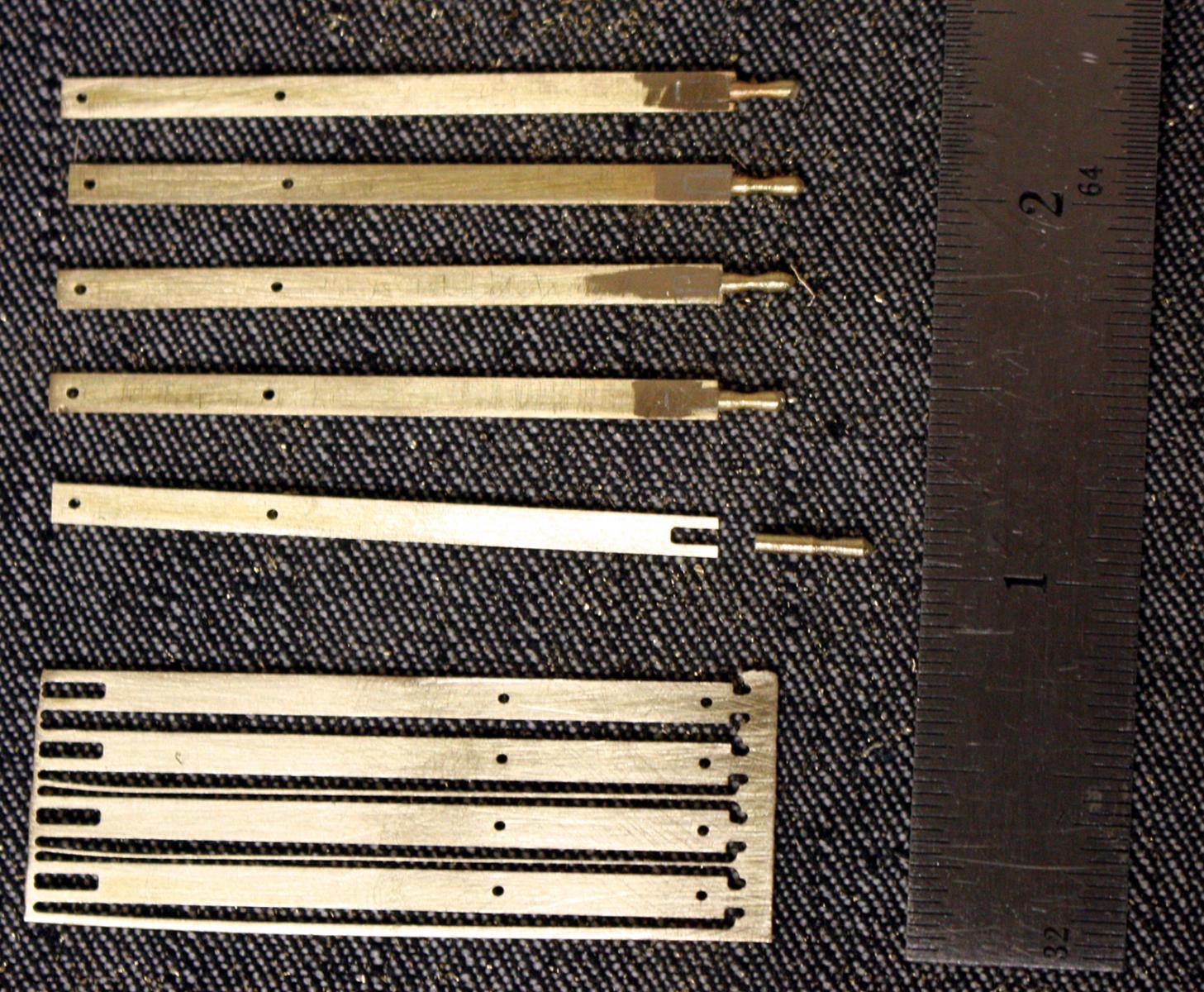
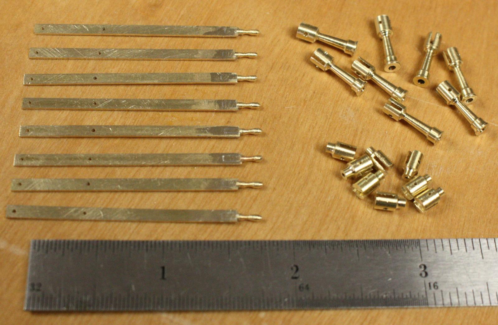
Valve levers fresh from the mill and before and after soldering.

Valve levers and risers.
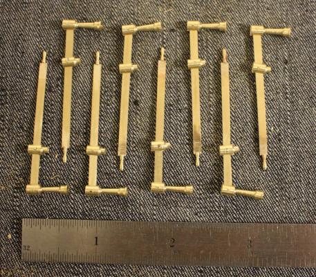
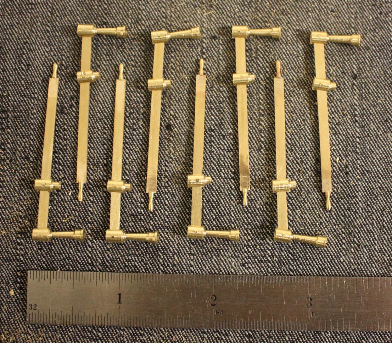
Assembled valve levers before blackening.
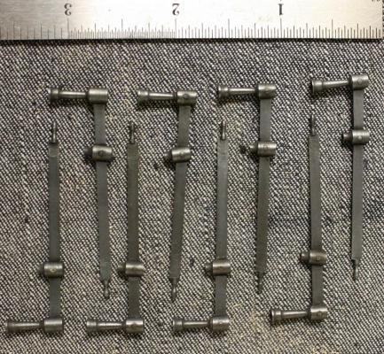
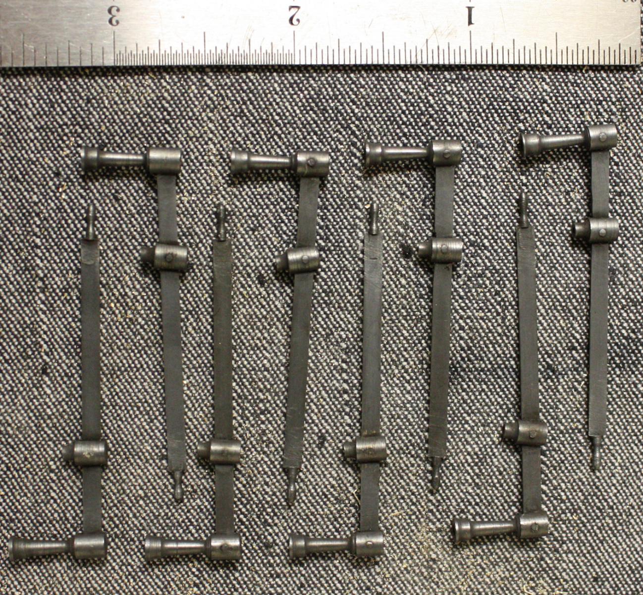
After blackening.
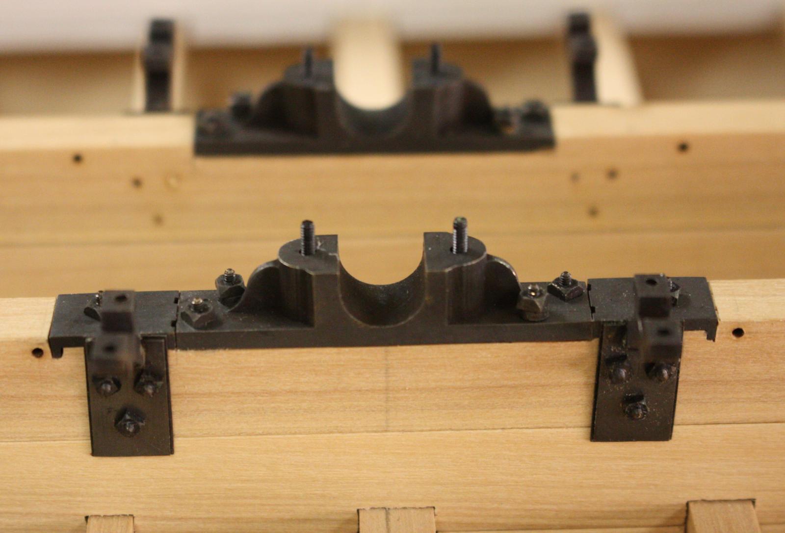
Cam frame supports and flywheel bearings after blackening.

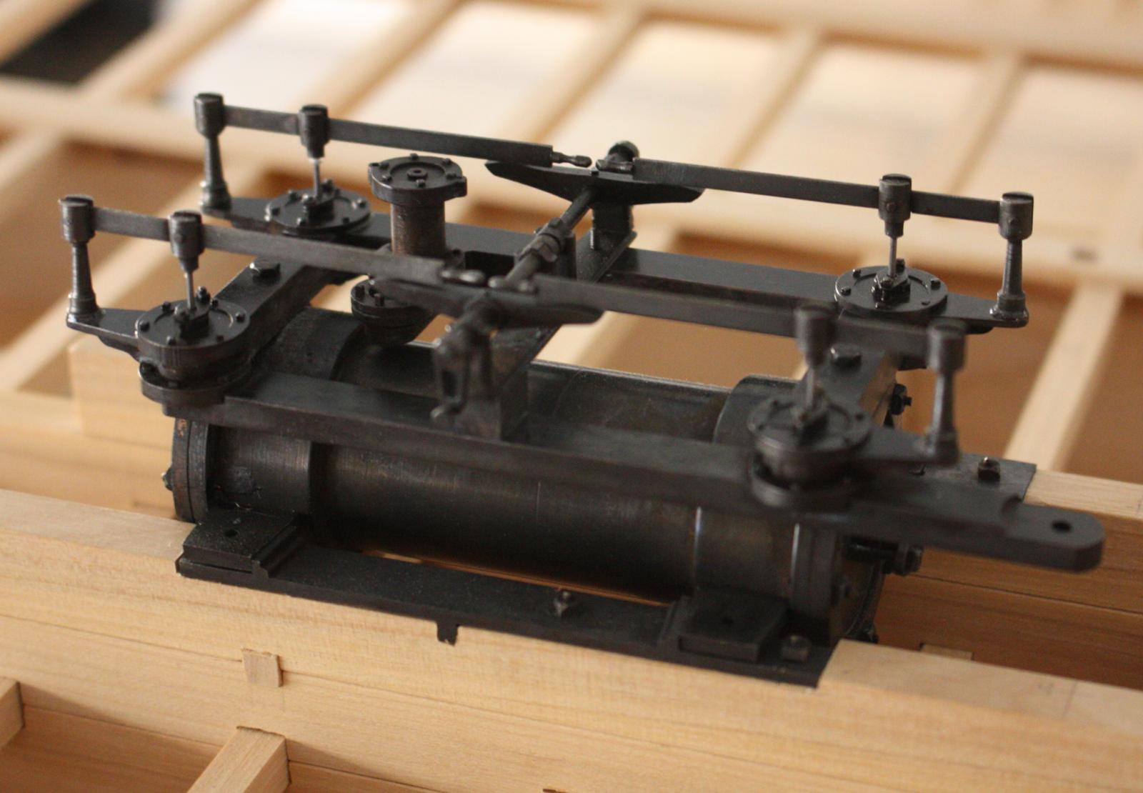
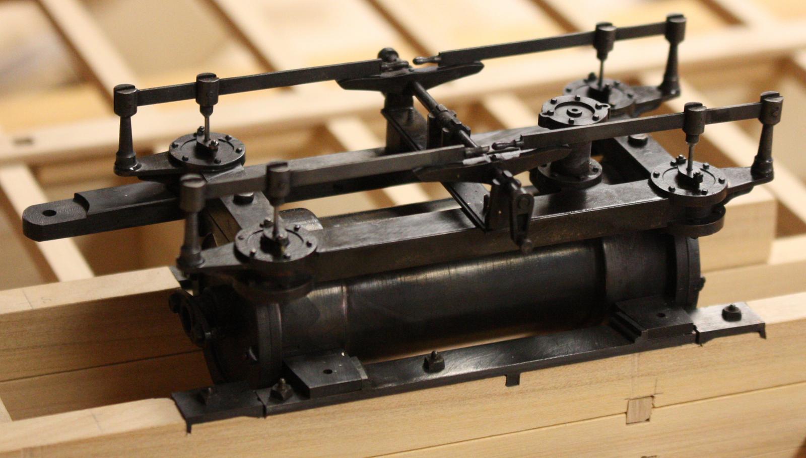
Port view of nearly completed engine.
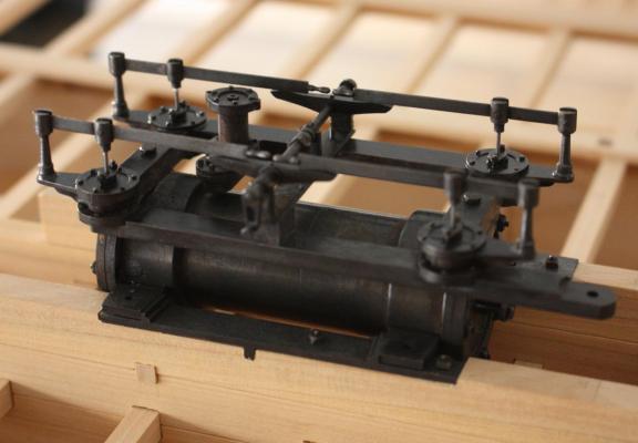
Starboard view.
- dgbot, Dimitris71, Cathead and 28 others
-
31


Heroine 1838 by ggrieco - FINISHED - Scale 1:24 - Western River Steamboat as she appeared before hitting a snag in the Red River
in - Build logs for subjects built 1801 - 1850
Posted
Thanks druxey, Michael and Cathead,
Your right Cathead, there isn't really much of the hull missing.