HOLIDAY DONATION DRIVE - SUPPORT MSW - DO YOUR PART TO KEEP THIS GREAT FORUM GOING! (Only 72 donations so far out of 49,000 members - Can we at least get 100? C'mon guys!)
×


tkay11
-
Posts
1,829 -
Joined
-
Last visited
Content Type
Profiles
Forums
Gallery
Events
Everything posted by tkay11
-
Most of my questions have been answered by an excellent masterclass on bandsaw use on YouTube. It is based on a Record bandsaw, but the lessons apply to any bandsaw. It is also longish at 50 minutes, but very well worth the entire video. It goes into depth about setting up a bandsaw, which blades to use, problems to avoid, maintenance, how to cut various types of timber, changing blades etc. You can find it at Tony
-
I agree, bruce. I'm also asking whether these small bandsaws manage 50mm thick lumber. I know they say they have 80mm depth of cut, but reviews seem to suggest they have difficulty in cutting to 50mm depth for the hard woods modellers work with. I would have thought it requires a lot of skill in addition to make sure such thicknesses are cut PAR if there is no fence. Are they up to the job I'm asking about? If so, are they all equally so? Tony
-
Just two questions about the Proxxon bandsaw, as well as other small (8-10") bandsaws: 1. On the Proxxon specifically I don't see a rip fence, so can you use it to re-saw logs to a constant thickness? 2. Several reviews of small bandsaws say they are not very good at re-sawing lumber over 25mm thick. What's the experience of people here? I need to cut pieces 50mm thick as that seems to be the common thickness of wood provided here in the UK, but have been put off buying a small bandsaw because of such reviews. Any advice, as always, is most welcome! Tony
-
Did you mean nitrocelluose wood sealer? Also, do you use the bleached shellac as the varnish, or the ordinary variety? I used to make up my own shellac from the flakes for finishing furniture, so I might be tempted to start doing that again for the ship models. Tony
-
 It's possibly true that the fashion for buying models made by someone else for home display is waning, but I can't remember throughout my lifetime ever having been in a home where someone has done just that -- apart from the simplified models bought at seaside stores and LEGO pirate ships and the like. Then there are plenty of people who have to make models of modern yachts and ships for the manufacturers and their excessively wealthy clients and governments -- as has been the case for centuries. Just recently druxey posted a picture of the most marvellous silver yacht model for auction at Sotheby's which sold for £10,625. However, I keep hearing that ship modelling itself is dying out, that younger people are not interested, etc. How true is this? It would be good to have some figures as otherwise such statements may be based on localised subjective opinion. It's not that I disagree, more that I don't know the statistics across the whole range of activities that would include ship modelling. From what I understand, ship modelling fora are growing rather than decreasing in size; in Eastern Europe the competitions still thrive (and card modelling is very popular); and there's a constant influx of people who have just retired and who try to find a hobby that is stimulating intellectually as well as practically in addition to giving satisfaction over a long period of time. In addition there are a whole host of professional model makers who work for a variety of different media at many different scales due to the constant demand for period films and tv shows. The skills and tools available to the model maker are unparalleled and new techniques are evolving all the time along with the need for new skills -- especially with computer programmes of a variety of types. Techniques used even in the 1990s have also evolved with the new ideas, the greater sharing of build logs on the internet, and with the available tools which need the parallel evolution of different complex skills. Do we have any statistics (global, national or local) to show whether ship model making (of whatever period) is waxing, waning or simply stable, and among which types of population? Tony
- 27 replies
-
- 5
-

-
- queen frederica
- cruise ship
- (and 3 more)
-
I think you have the wrong size cannon. It doesn't look like a 3-pounder to me, and the Sherbourne was said to carry 3-pounders. Yours seems much too large. The carriage length should be 14.3mm for a real 3-pounder at 1:64, and the gun barrel length 26.8mm. I can't remember the kit gun sizes, but the kit barrel lengths were for a 3.5 pounder gun at scale. Perhaps you could measure the gun barrel length, the height of the assembled gun from the ground and the length of the carriage. I compared the sizes in my build log. You can see the final gun build with a full discussion and comparison on Page 6 at I attach the real plans for an Armstrong 3-pounder. ARMSTRONG 3 POUNDER S1.PDF ARMSTRONG 3 POUNDER S2.PDF Tony
-
It's difficult to say without a photo. Your particular difficulty seems to be a little different to the problem with the fitting of the cannon through the gunports in other Sherbourne builds. What cannon are you using? Are the guns horizontal? Have you already made them from the kit or are you using card cutouts? Tony
-
I am looking to adapt my Proxxon DB250 wood lathe to accept ER16 collets because although this lathe comes with some collets, there is a gap between the 4 and 6mm sizes. The Proxxon lathe has an M16 spindle, and I already have a 3/4-16 adapter for ER16 collets on my Taig Lathe which uses an ER16A clamping nut on the adapter. So the question is: does anyone know of a supplier of an adapter (a) from M16 spindle to 3/4-16 nut, or (b) from M16 spindle to any kind of ER16 collet holder or to an ER16A clamping nut? Another question would be if there is anyone willing to machine such an adapter for me, for which I would willing pay the fee. Thanks Tony
-
- 1
-
-
Well said, wefalck and Dr PR. Another way of looking at it is to say that if you can hardly see them with your eyes 5-6ft away on a real ship, then at 1/64, with plugs 0.5mm diameter, imagine trying to see them 5 x 64 = 320ft away. There are so many conventions in building models of models: the framing of Admiralty style models for example. But in such conventions there is another consideration: the beauty of the model itself, which is perhaps what people try to replicate. Tony
-
Thanks, allanyed, it may indeed need to go below the thwarts. Unfortunately while in the real world the thwarts were removable, I've just realised that I didn't think ahead for the model and I have fixed the thwarts very firmly in, knees and all. I tried putting it under the thwarts and then spent a good time trying to extricate it again -- a bit like one of those 3D puzzles. @wefalck: I can see that I may well have to follow that idea and hang it over the rail. The 20 oars are also going to have to work out where they'll occupy space or else be wrapped and carried on either side. Tony
-
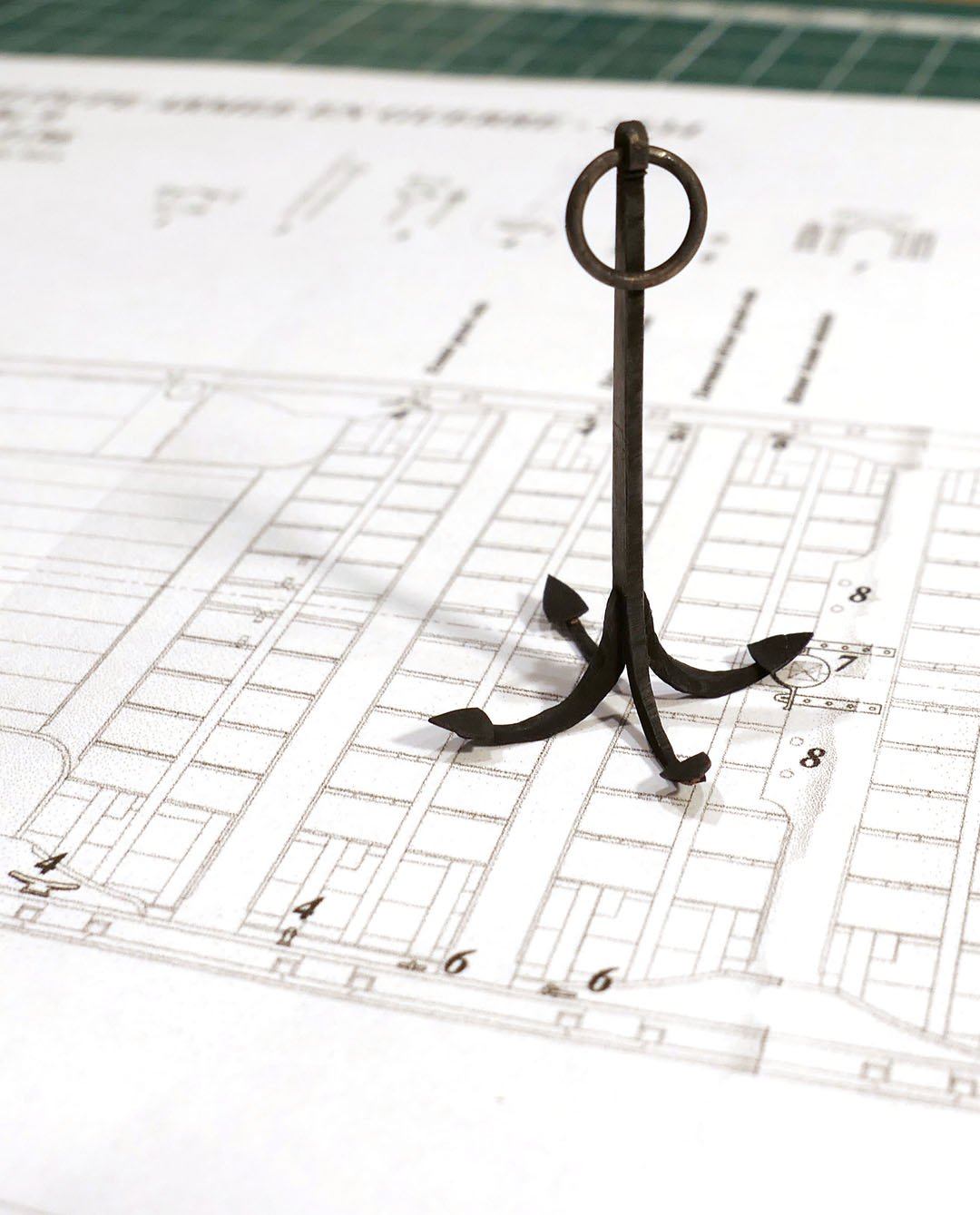
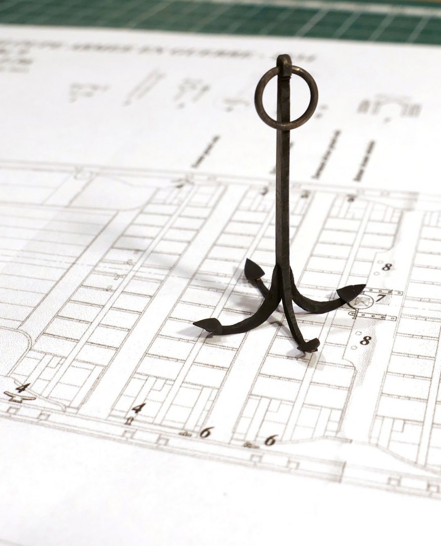
I am making the various accessories for my build of the Chaloupe Armée, a 42ft 1834 French Armed Longboat. I have made the grapnel anchor as per the picture, but, having done so, wonder how and where it would have been stowed on the boat as it has such an awkward shape and was clearly quite hefty. It's 40mm long at 1:36. I'd be really grateful for any advice or comments. Thanks, Tony
-
Treenails on a deck are barely visible on a real ship. Check this out with some photos, e.g. of HMS Victory where you can just make out the slightly lighter shade of the plugs covering the bolts in the deck. Typically they're about 32-38mm, so at 1:64 about 0.55mm wide. At 1:64, you have to imagine yourself staring down at a deck from 64 x 5ft = 320ft and thinking how visible those treenails would be. Some modellers manage to do it in a very subtle way by lining the holes with a gentle edging of lead pencil and filling with some very similar-coloured filler or wax. all you have to do is practice on some spare planking until you have found the level of visibility that pleases you. But there's no shame in not demonstrating them. Tony
-
L'Egyptienne of 1799 also had them, according to the new monograph by M. Delacroix. Tony
-
The Proxxon DSH scroll saws come up regularly on eBay for about £100. I bought a refurbished one from Axminster for that price on eBay and it works fine. The only thing is that you really do have to finish off with a sander, or careful sanding, and I now tend to use a coping saw much more now that I have built my own jeweller's bench pin. The problem I have with the coping saw is that I still find it difficult to make perfectly vertical cuts all the way round. But I suppose that's something that comes with experience. Tony
-
Welcome to the club of self-inflicted errors of which I am a member. I am sure there is a very large (though uncounted) membership. It's one of the best ways of learning as such errors burn so deep. And take heart: it reveals an independent or perhaps an experimental mind. Some of the world's most remarkable discoveries have been made by ignoring centuries' old advice, though admittedly such discoveries are very rare. Tony
-
The idea of laying one plank from front to rear may be part of the advice to lay strips that will guide the division of bands. I don't think this would be for permanent use. Normally model makers would use string or thread to do this, but in real life the shipbuilders would place planks along the hull for this function. Tony
-
I don't really understand your question about the first plank that goes against the bulwark, but there isn't a plank that goes all the way from bow to stern. Hull planks were generally 20-24ft long (@1/64 = 4.5" or 114mm). The Sherbourne was 54'6" long, so would have 2-3 planks per strake. Planks are indeed curved at the bow and the stern, and Chuck's planking videos demonstrate how to do this using heat alone. Normally (as you'll also see in the various planking tutorials) you have to calculate the width of the planks at each bulkhead, either using a fan of lines (the easiest) or by arithmetic. It would be very difficult just to use the full width of the plank and adjust the width as you go. One immediate problem would be how you would work out how to shape the first plank you laid. You would then get into real difficulties as the number of strakes increases, unless, of course, you don't mind your planking to look a real mess which you would hope to cover up with paint. As you will have seen from the videos, the easier way is to start by working out in advance how many strakes of planking you will need for the hull. At its very simplest, this is done by measuring the distance between the top of the largest (midpoint) bulkhead (at the position of the first strake) and the keel using a piece of string or thread along its curve. You then take the width of the planks you have (I think the kit ones are 5mm) and divide that into the length you have found. So if the length of the bulkhead is 100mm, that divided by 5 would give you 20 strakes. So you now aim to have 20 strakes at the bow and 20 at the stern. This may be impossible as you can't have planks that are too narrow at their ends, so this is one reason why you may be forced to add a stealer. The determination of the number of strakes allows you to take each bulkhead and divide its curve length by 20, and mark off each width accordingly with a pencil on the bulkhead. Most people divide the hull into bands, and plank each band in turn to help avoid problems of 'cutting creep'. You also have to take into account that the garboard plank will be wider than the others. It may be a good idea to look at the printed guides to planking provided in the resource centre on this site, in addition to the videos, as that may allow you to absorb more fully the various ways in which planking can be approached. I hope this helps and that I haven't muddled things even further! Tony
-
I seem to remember the main difficulty was with the carriages and trucks, especially extracting the carriage wheels. The other difficulty was ensuring the correct height of the gunports as they vary along the side. I had to cut cardboard outlines of the guns in their carriages in order to ensure they fitted properly in the gunports. Ideally, this should be checked before you plank the bulwarks. Tony
-
Good to have another Sherbourner! You've probably seen them, but if not, I strongly recommend the Dubz, Gregor and Stockholm Tar builds for interesting discussions as well as hints and tips. Dubz (Dirk) put the keel, stem and stern on after the first planking and before the second. That allows you to use them as a kind of rabbet -- although it might be best to leave the sternpost off till after the second planking as there is no rabbet on the stern and you can cut off the planks absolutely square without a problem if it's not there. Why not have a look at the state of the model after the first planking and then decide? I wish in hindsight I had not placed them before any planking, or at least had protected them with tape, as they ended up with lots of scratches from sanding. Tony
-
I wouldn't regard the build logs as master works, more as guides, hints and tips as to how to approach the various problems you definitely will encounter. Of course some of the builders may have more builds to their name than you have, but I, for example, had as my first kit the Sherbourne and immediately was given a great deal of help by others (some of whom had never built a Sherbourne). I benefited hugely from reading the logs in detail and then deciding whether I could have a go at some changes to the kit or not. I very quickly came to the conclusion that it wasn't that hard to modify the kit in various ways and in the end the only bits of the kit I used were the internal bulkheads, the first layer of planking, the keel, stem and stern, the rudder, the nameplate and the anchors. I had no previous experience other than assembling simple plastic kits as a young boy, and had never done anything like a wooden kit. Others prefer to stick to the kit. Whatever you choose, you'll end up with something you're proud of and you'll have learned a lot. The end result was nowhere near their perfection, but I certainly had a great time learning! So my message is, don't be frightened of what you see as others' perfection. Everyone on this site started as complete novices some time, and they all have experienced the same problems and mistakes that you will. The members are a really helpful lot, so don't be afraid to ask questions. There really isn't any question that is too stupid to pose! I hope that helps a bit! Tony
- 10 replies
-
- 4
-
-
- sherbourne
- caldercraft
- (and 1 more)
-
A good start. Watch out for the height of the gunports above the deck so as to allow the cannon to go through without a problem. You can make a card cutout of a gun in order to do this. Glue stains on wood have a nasty habit of poking through, so you may need more than one layer of paint. It's worthwhile thinking about how to use the minimum amount of glue to avoid spill. If you're using PVA a quick wipe with a damp cloth on any excess will do the trick. Another way is to use a toothpick to pick up excess from corners immediately after gluing. CA glue is much harder to hide or wipe, so you need to be much more careful with that. I'd also protect the stem, keel and stern from further damage as you plank and sand. Some people put these on after planking in order to avoid the damage, but putting tape over them will also work. As you know, luckily there are lots of excellent build logs of the Sherbourne on this site which really are worth studying. They will help you with such details, will point out pitfalls to avoid before you get to them, and people no doubt will also pop in to help you as you progress. It's an excellent model to start with, and allows you many possibilities for improvement as you get into it. Tony
- 10 replies
-
- 1
-
-
- sherbourne
- caldercraft
- (and 1 more)
-
Sorry to butt in, Vaddoc, but I'd like to ask a question. I've enjoyed this thread as it has gone into the difficulties of 3D design. It makes me ponder all the more at the work that goes into the various 3D designs on this site based on old plans (the fully rigged Swan class 3D model being one amazing example) which seem to have all the right parts in the right order in the right places (with acknowledgements to Eric Morecombe). Like some others, I also use 2D CAD a lot to replicate parts of plans, design my own parts, double check dimensions etc., but I have often wondered how to use a CAD programme to 'straighten out' the planks to provide their accurate flat dimensions before bending. This seems a very useful function of CAD in order to be able to predict (albeit roughly) the width of planks to cut and therefore of amounts of wood to order. So, as an aside, would you be able to provide a quick tutorial on how this is done, or point me to somewhere I could find out about that? Thanks Tony
-
I forgot to say I still struggle with the planking myself, but, as you suggest, every time I do it I get a bit better! At least I think I know how it should be done! Tony
-
I don't know if you've read the various planking tutorials on this site, but just in case you haven't they're really worth studying. If you go to the forum for "Building, Framing, Planking and plating a ships hull and deck" this points you to the planking tutorials. Chuck's tutorials are particularly good on spiling and bending with heat alone (i.e. without soaking the wood or using steam). Tony
-
Just catching up with a few months away from following build logs, so sorry if I'm butting in a bit too late. I've been considering whether to build a Triton full build, so it's been interesting to follow your own progress. With regard to your comments about the difficulties with your planking, it may be an artefact of the way the photos are taken, but I can't see the pencil markings for your plank widths on the last two bulkheads. The width of the planks at the stern seem to be wider than the marks on the third last bulkhead would suggest. Might that be a source of difficulty? Tony