tkay11
-
Posts
1,829 -
Joined
-
Last visited
Content Type
Profiles
Forums
Gallery
Events
Everything posted by tkay11
-

whats an easier build for a first kit
tkay11 replied to rdestefano01's topic in Wood ship model kits
Apparently the bulk of those who buy wood model kits give up once they find how much time it takes to get their heads around the various challenges they come across once they start. This is the reason why the advice often given is to start with a small kit that has lots of builds on this or any of the other various ship building fora -- that way it's very hard to go wrong, and there's lots of support from others to help you over the difficulties. So the advice given here to buy both kits sounds pretty good to me as well. You may well find that once you get your teeth into the smaller build you'll enjoy it far more than you might have thought. A great deal of the fun is just figuring out how to do the next step. I've only just completed my first build and it's been a joy from start to finish even though I had initially wanted to make a different model when I started. I did set out, though, with the idea that the first model was principally to develop a range of skills and to see whether I would like the hobby. It also very much depends on your personality. If you are determined to see it through, no matter what difficulties spring up, I would think you'd be able to tackle any model -- especially if you have lots of others building the same model so you can share solutions and advice. I wouldn't worry about achieving 'perfection' -- there's not really any such thing -- as long as you've enjoyed doing it. It's just that sometimes you have to stick at it through some frustrations until you find that overcoming the frustrations is part of the fun! Good luck! Tony -
Thanks a lot, everyone, for the likes and comments. I can now feel I've made a contribution on the forum after the learning I've had from you all. Peter: Next is the Triton cross-section which I'm planning, having started the keel parts and obtained the plans. Glad you like the stand! Dirk: You've been a huge inspiration to me with your own Sherbourne and other builds, so your kind words are very much appreciated. Tony
- 269 replies
-
- 3
-

-
- Caldercraft
- First build
- (and 3 more)
-
Thanks, Nils. It's really great when experienced modellers as yourself who produce beautiful and finely crafted work give me such comments. Tony
- 269 replies
-
- 3
-
-
- Caldercraft
- First build
- (and 3 more)
-
Thanks a lot, B.E.! My wife hasn't anything to compare it to, but definitely the small size is a plus since it's going into a bookcase. Tony
- 269 replies
-
- 1
-
-
- Caldercraft
- First build
- (and 3 more)
-
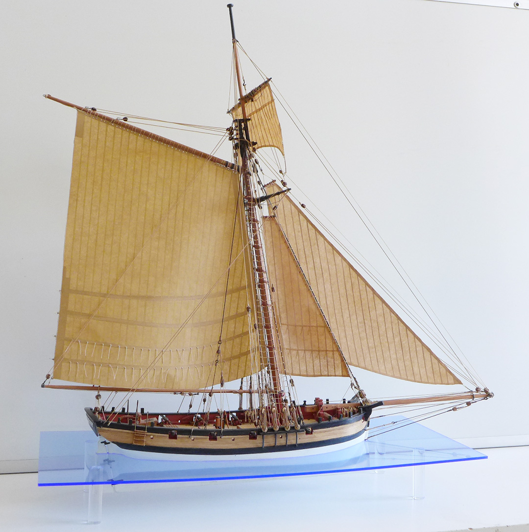
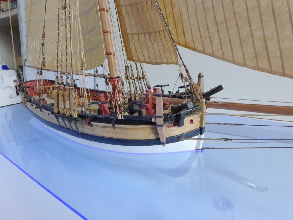
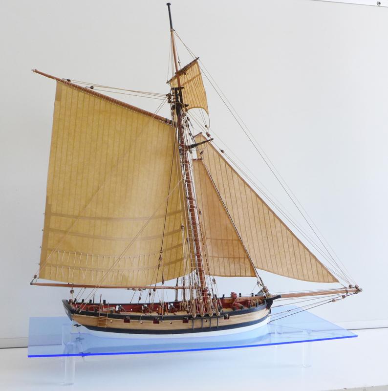
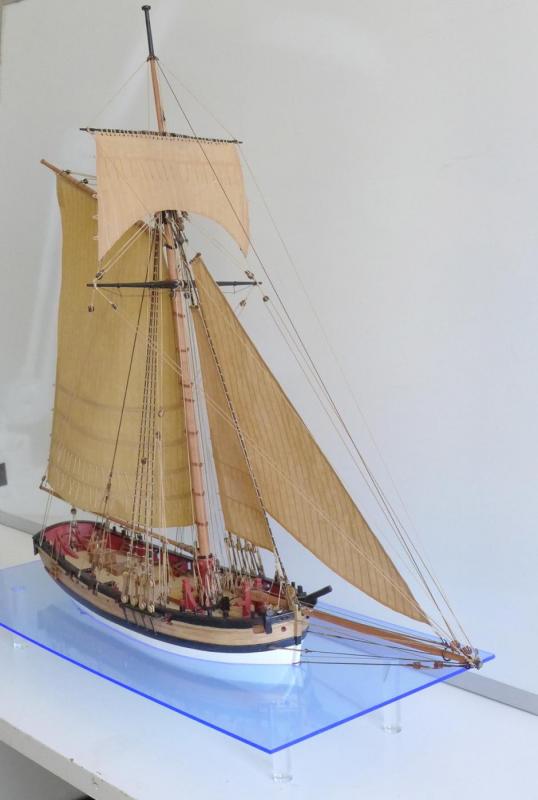
MODEL COMPLETED! OK, there’s lots I haven’t added. Such as: the full and correct rigging for the 3-pounders, perhaps the lids for the gunports, rigging the catheads, deck furniture, flags, horsehoes on the stem, waterline marks, clew lines, leech lines, bunt lines and a whole lot more that all you experienced builders will note immediately. There’s also a whole lot that is messy, imprecise or badly finished (I still groan over the blocks). BUT … I’ve achieved what I set out to do: to dip my hand into the waters of wooden model boat building, obtain a grasp of the various dimensions of the hobby, and pick up some of the various skills needed to continue with the hobby. These have been done with enormous pleasure at every step of the way. In particular I have loved the variety of challenges that had me puzzling for days until I was able to find some way of dealing with them. In fact, and perhaps oddly, I have slightly less pleasure in having arrived at the end than in the enormous pleasure I have had in dealing with particular parts. Something that really did please me, for example, was finding out how to make and use gravers to turn the brass swivel guns. All the same, my wife likes it! I wanted to give the model away to a local library or shop, but she’s demanding we keep it – at least until my next build is over. WHAT I HAVE LEARNT Now that I have finished the Sherbourne, I thought it a good point at which to summarise for the benefit of other newcomers what I have been learning as a result of starting this hobby. Keep A Build Log! Most important, perhaps, is the enormous value of keeping a build log. Doing so forces you to review your progress methodically and at the same time helps you to learn from others as they comment on your progress and guide you where necessary. I also wanted to use my log to help other beginners who may be puzzling over how to manage various stages: my steps may provide a few more options for them to consider. Start with a simple kit of a small ship! The Sherbourne kit really is an excellent kit for a first-time builder such as myself. Should I have wanted to, I could have just proceeded with the kit parts and plans as supplied and finished the whole thing in about three months. However, as it is based on plans in the UK’s National Maritime Museum it tempts those who want to go further and make it more like it might have looked in the 18th Century. Don’t be scared: take the plunge and build your own parts! A review of all the other far more expert builders who were and are tackling the Sherbourne showed lots of different possibilities, and I quickly realised that every modeller was making a unique creation of their own. I was gradually drawn in to making modifications of my own as I realised that I might be able to make various parts myself when I observed others doing so. It started with the rudder, pintles and gudgeons. Then deck fittings – the hatches, companionway and pumps. Then I realised I might have a bash at making the gratings a bit better. Then I took on the cannon, belaying pins, rope, masts, bowsprit, yards, jeers, windlass, blocks, anchors, swivel guns, boom crutch, hooks, sails, rudder coat, yard horses, foresail horse and, to my great surprise, a Perspex sheet for the waterline stand. All of this came about as a result of the wonderful support from other modellers on the forum, as well as lots of reading, research and visits to museums to inspect contemporary models. Skills that come your way when you try Of the many skills I have been picking up, those that pleased me most have included: * Accurate sawing with a table saw * Using a Proxxon mini-drill and converting it to use as a wood mill * Turning with a wood lathe (masts, spars, ebony cannon) * Using a metal lathe to turn brass swivel guns (a Taig/Peatol) and making gravers to do so * The value of a disc sander * Silver soldering with a really basic butane torch * Blackening brass * Understanding ship plans * The value of a software CAD programme (TurboCAD) to trace plans and draw up my own to make particular parts (e.g. cannon) * Making my own stains for rigging and wood * Sharpening and honing * Cutting and welding Perspex sheet and rod. Don’t be worried that at the end of it all your skills are not as good as others! Of course my ability with these skills is nowhere near as good as very many other modellers on this and other fora, but the point of my drawing up this list is to point out to those who are starting a wooden ship kit for the very first time that you may well be surprised at how rapidly you can take on skills which at first seem impossible. Even more: by taking on some or all of the new challenges you discover how deeply and broadly rewarding this hobby is in maintaining and generating learning, and in figuring out how to overcome new challenges. It’s far better than computer gaming (in my opinion)! Better still: the process of learning continues endlessly, no matter how high your skill set is! So it’s with the wonderful understanding that I’ll be learning a great deal more, and encountering a whole new range of challenges, that I’m now organising myself to start on a new level – how to make frames with the Triton cross-section that is so generously supported in this forum. Tony


- 269 replies
-
- 16
-
-
- Caldercraft
- First build
- (and 3 more)
-
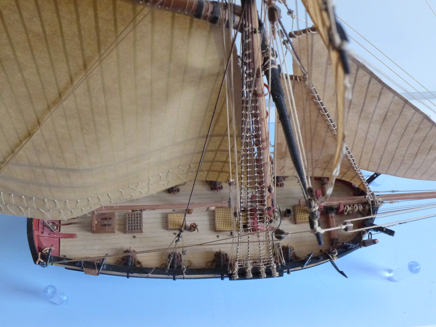
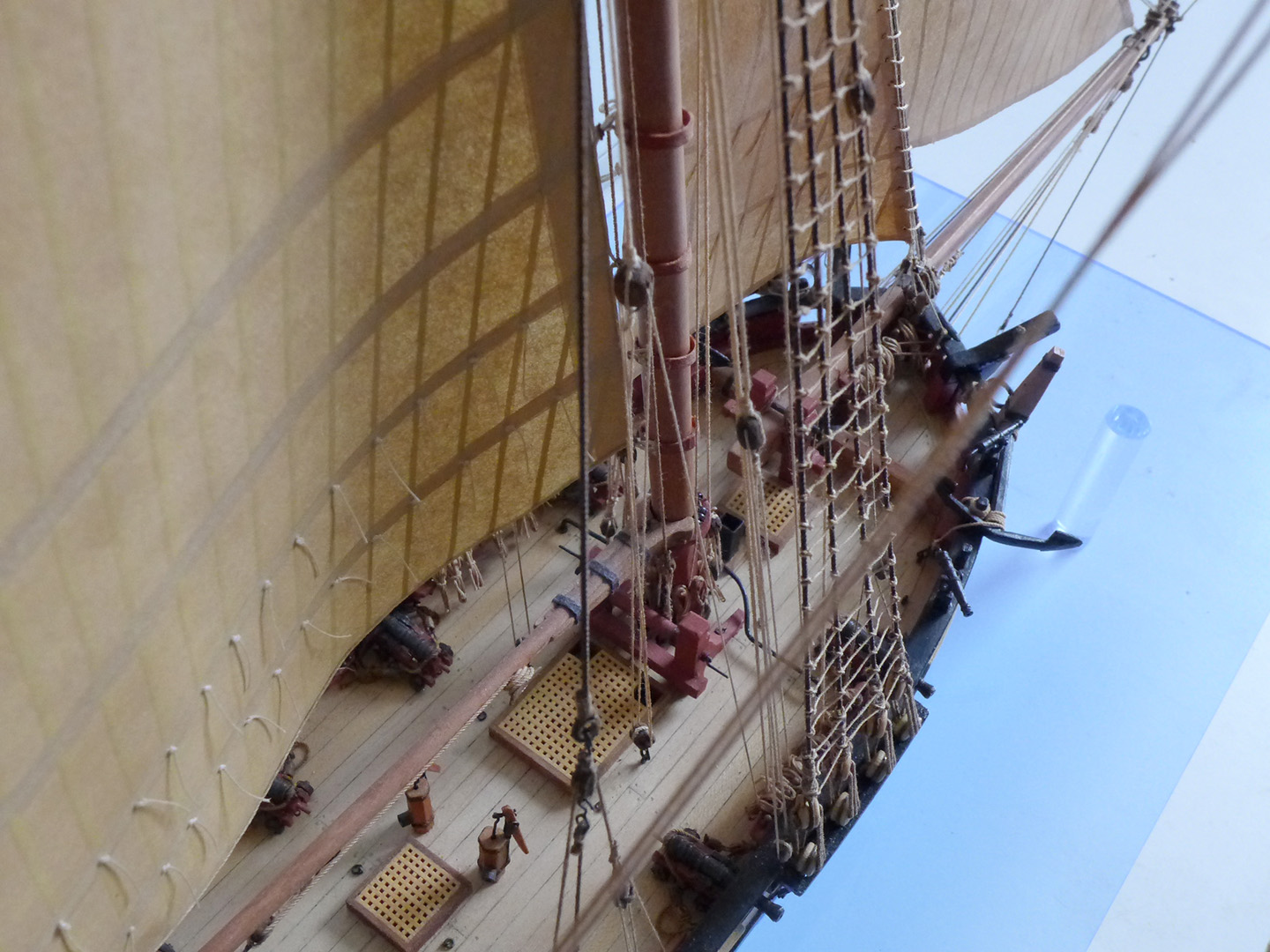
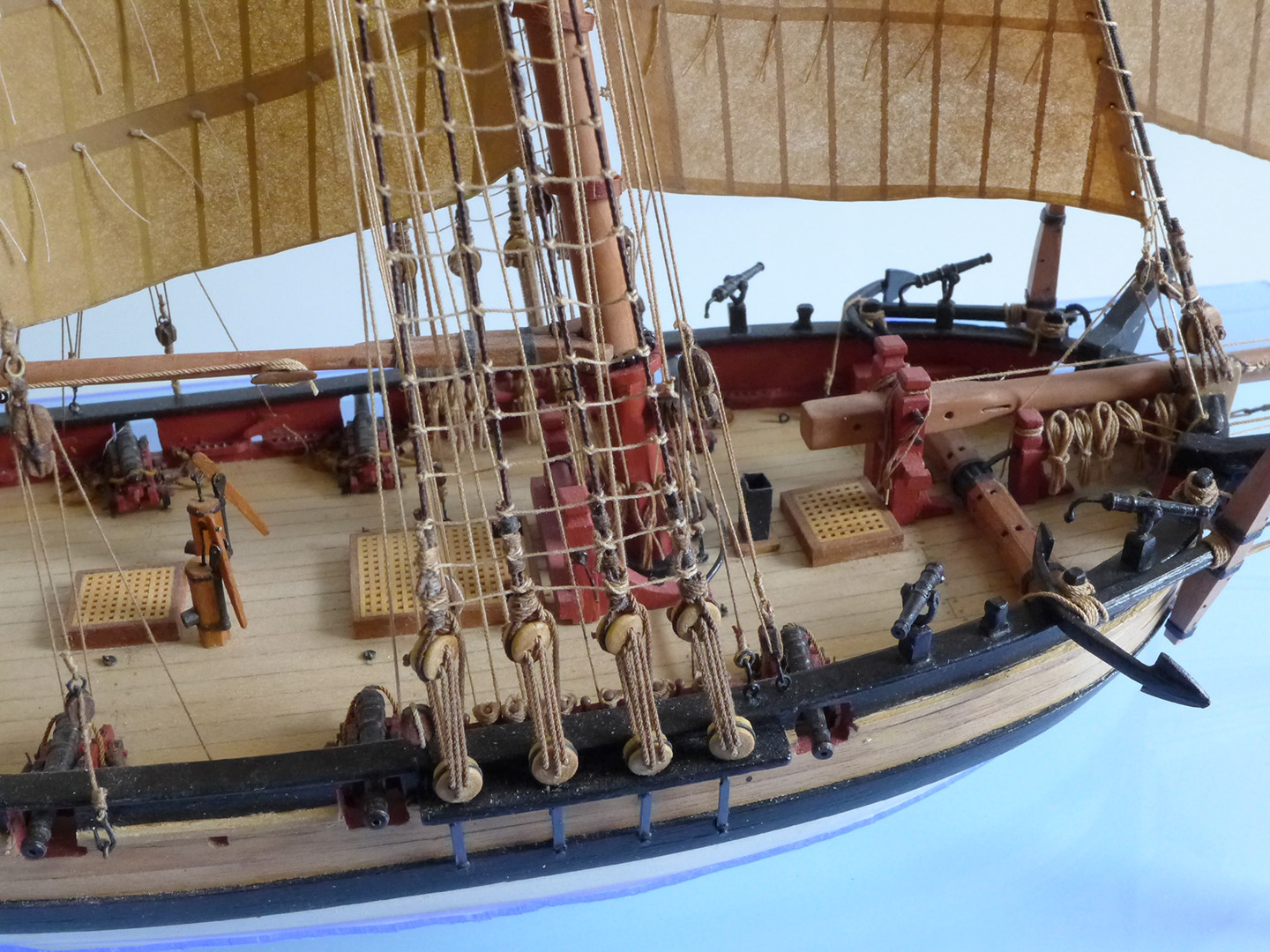
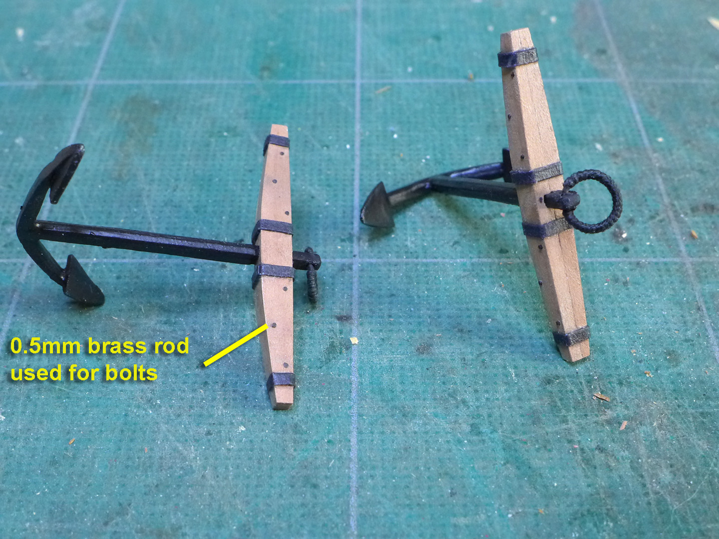
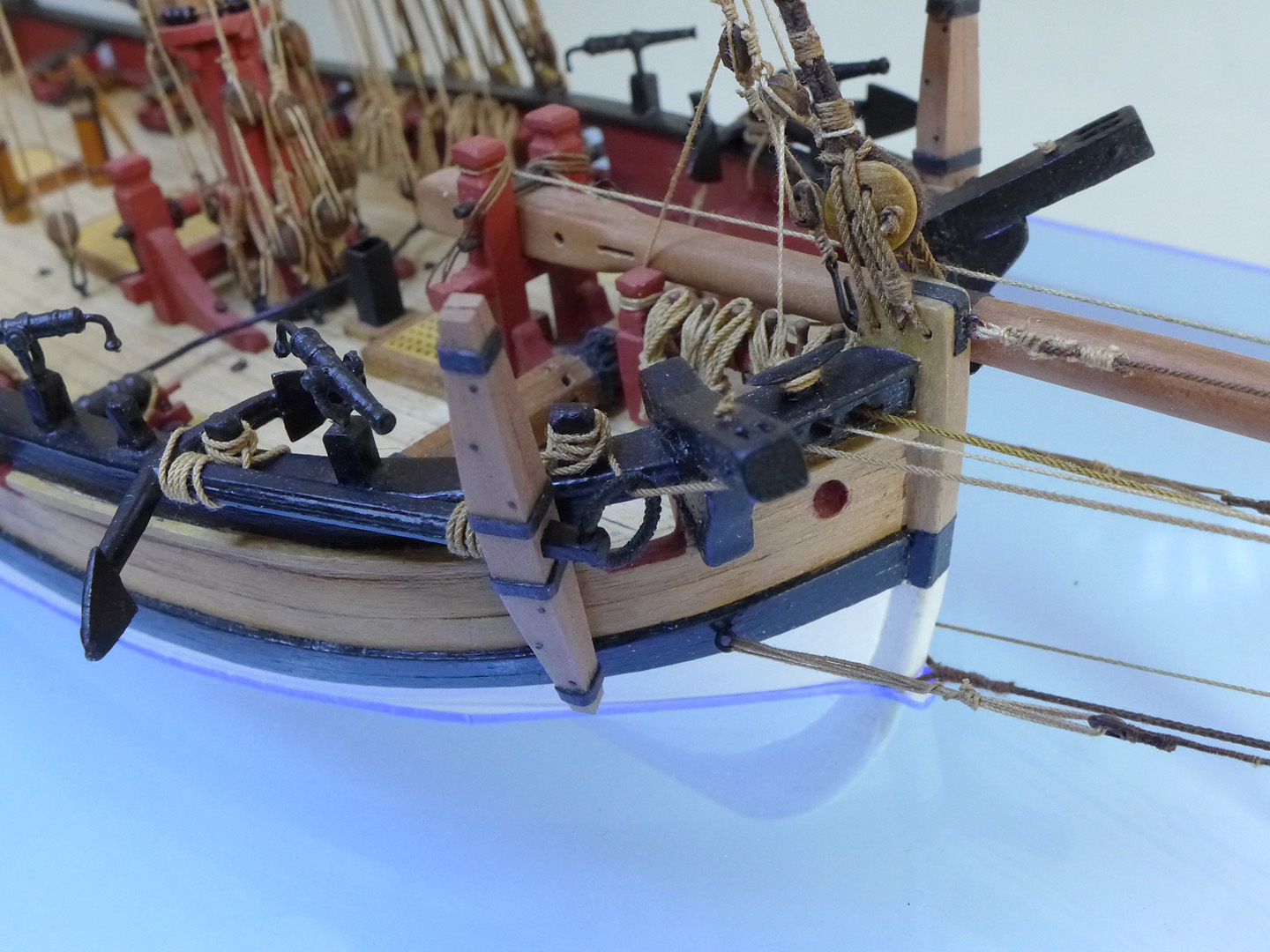
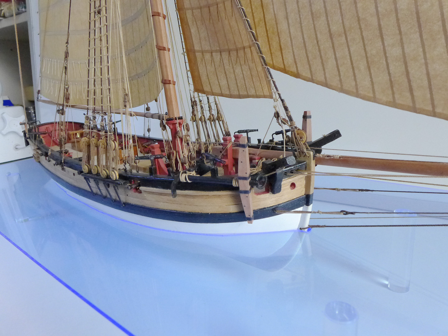
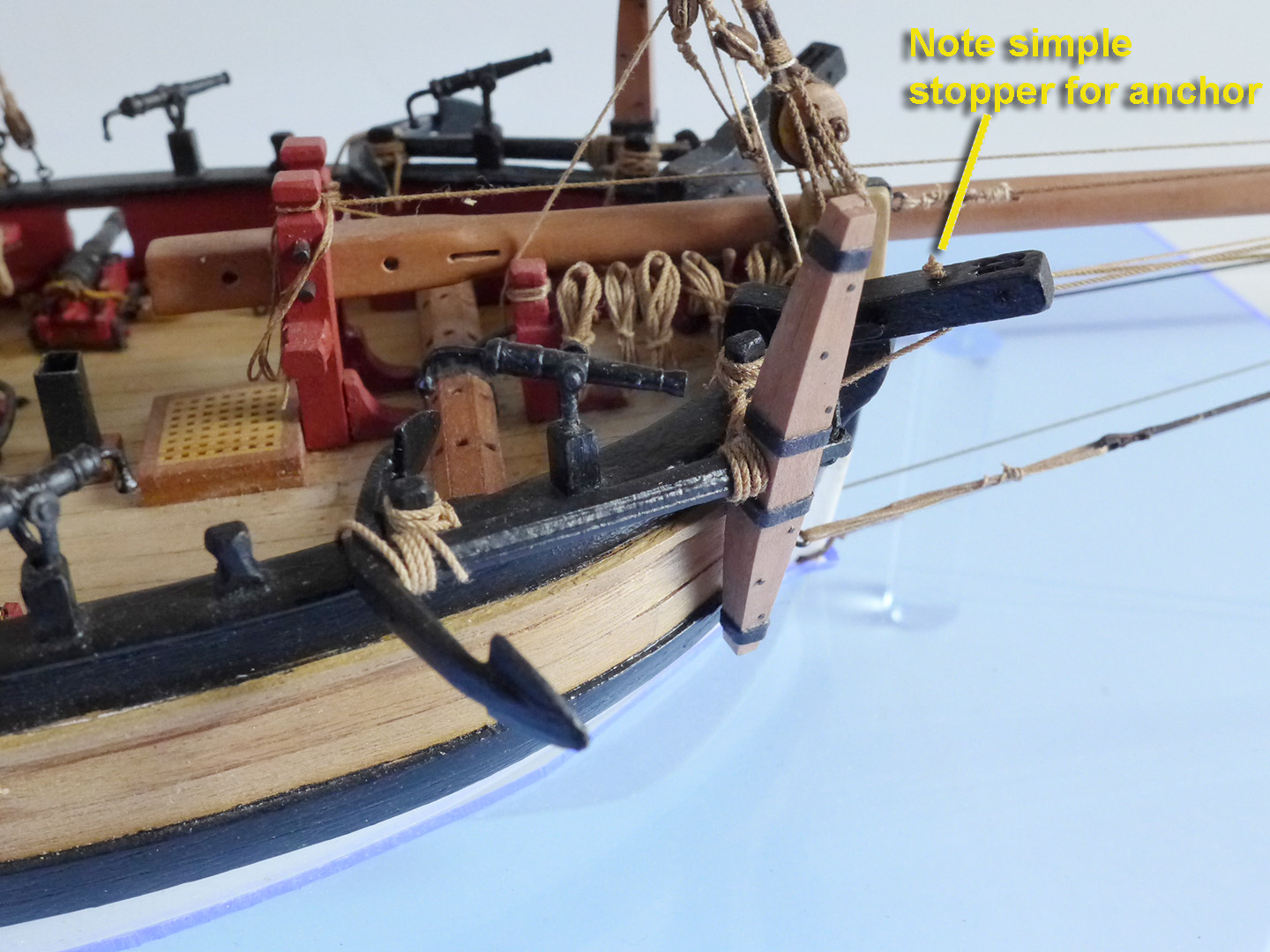
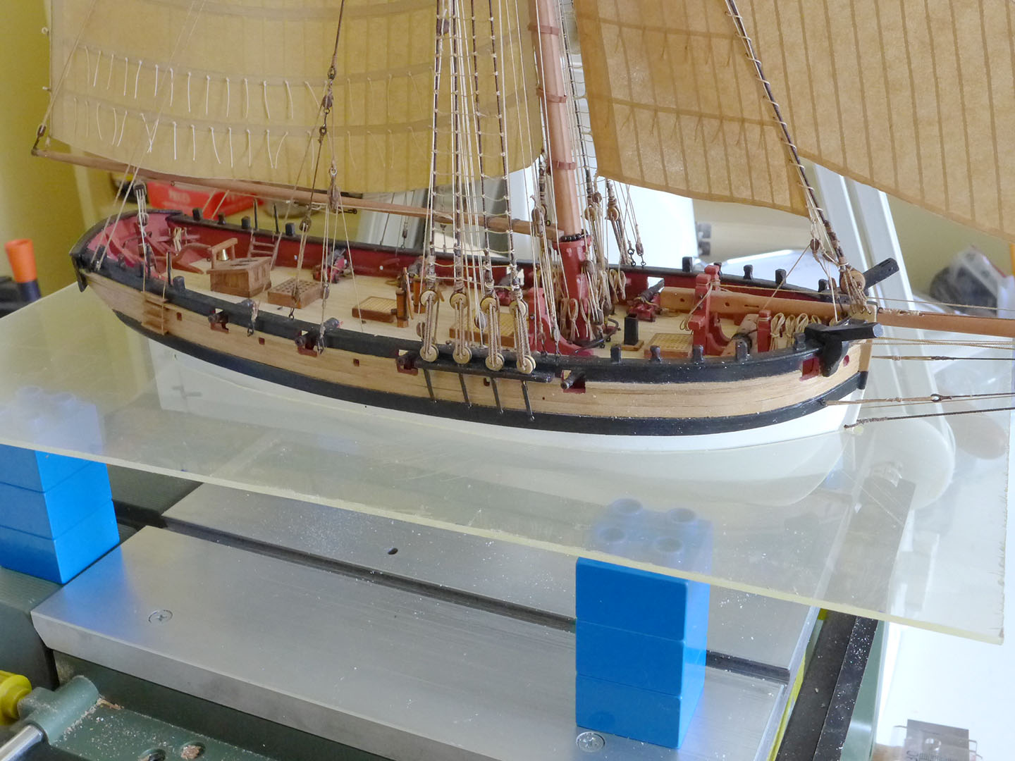
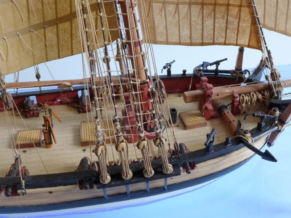
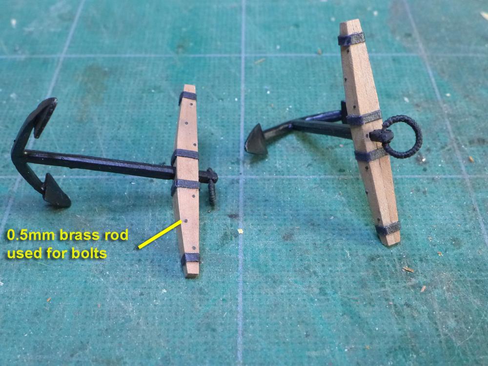
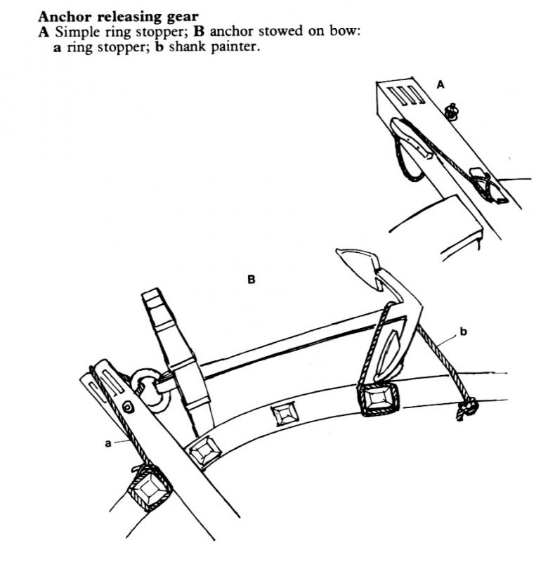
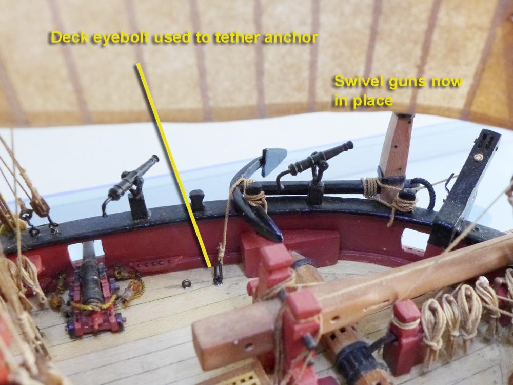
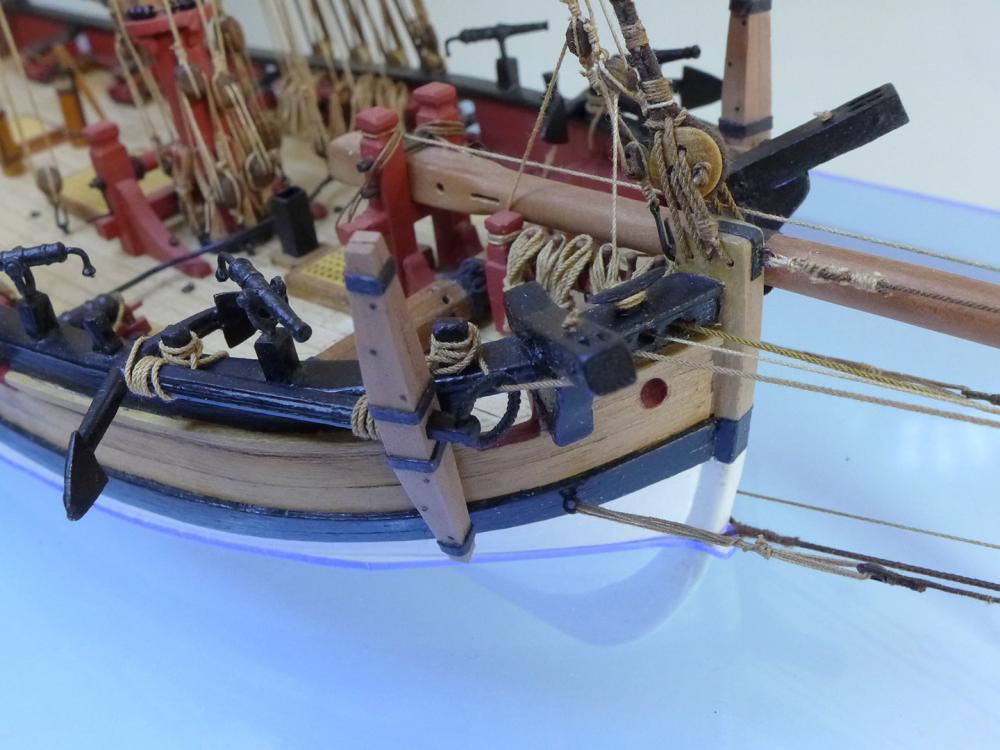
ANCHORS As usual, I had thought I might be able to make the anchors from the kit parts, but the moment I tried to fit the wooden stock I found (as have so many before me) that the channels cut in the stocks are too wide for the shanks. So I had to make my own stocks. I used a pear offcut I had and dimensioned it using the dimensions given by zu Mondfeld in his book Historic Ship Models. I drilled 0.5mm holes for the bolts, used 0.5mm brass rod to fill them, and touched the ends with undiluted brass blackener to blacken them. As is the norm, I used 1mm black cartridge paper to mimic the iron rings round the stocks. For the puddening of the ring I used black polyester thread, using CA glue to hold the first part in place on the ring. STOWING THE ANCHOR After a short discussion elsewhere on the forum, I decided I’d stow the anchors as for sailing (since the sails are up and the model is on a sea of Perspex). I followed Harland’s diagram (Seamanship in the Age of Sail) and used a simple stop in the catheads to hold the rope for the stock end. Interestingly I had been puzzling about the use of two eyebolts shown on the plans for the kit placed in the deck just aft of the windlass. I decided that one of them would be perfect to hold one end of the rope for the crown end of the anchor. The following pictures show how the anchors are stowed. That's it. Next up: reflections on completed model. Tony

- 269 replies
-
- 12
-
-
- Caldercraft
- First build
- (and 3 more)
-
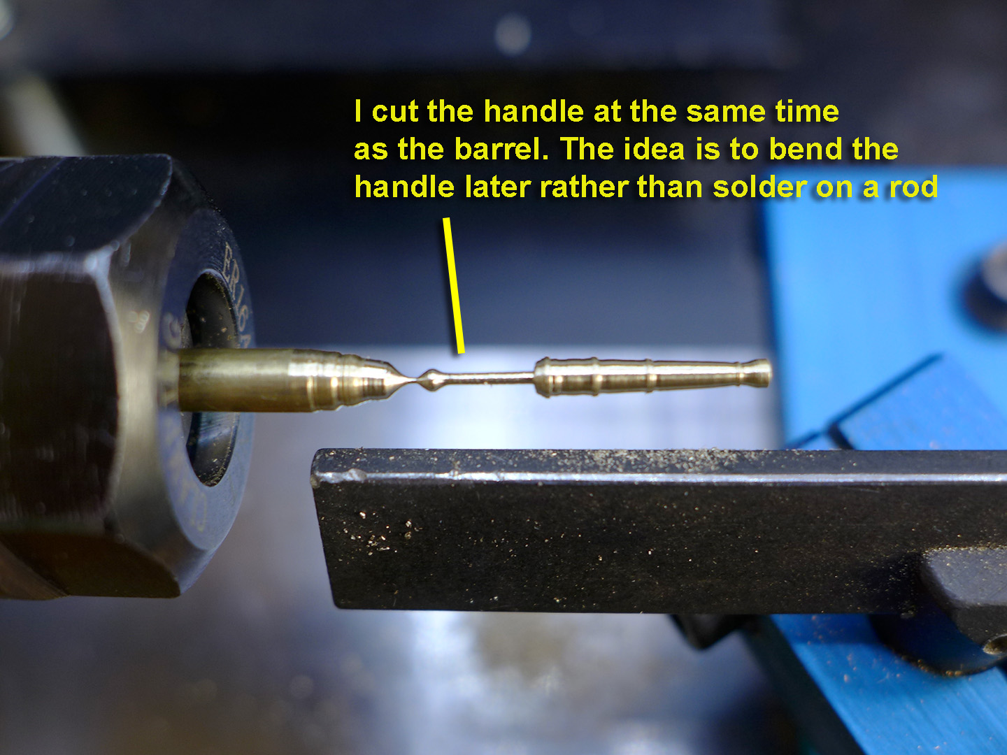
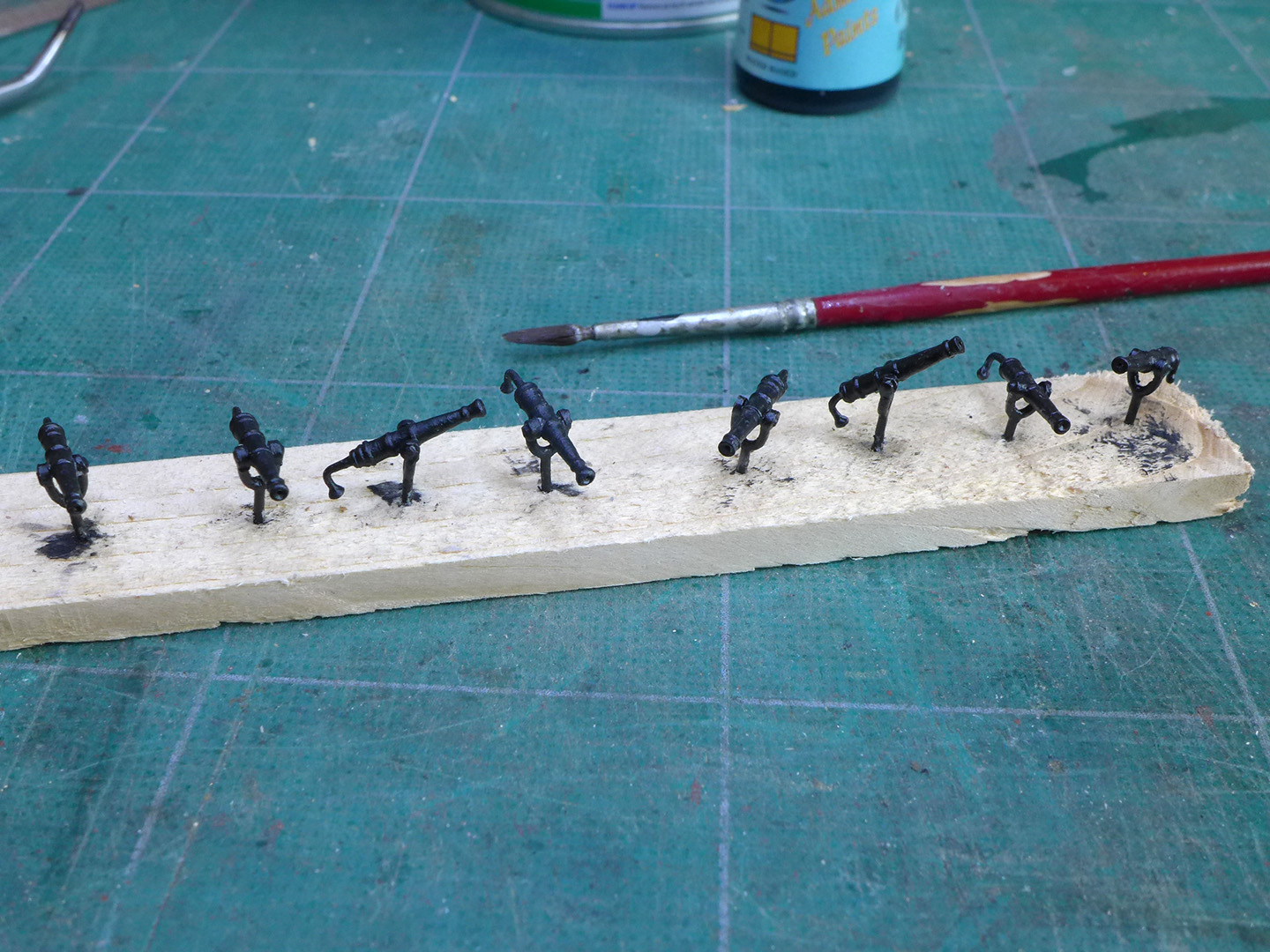
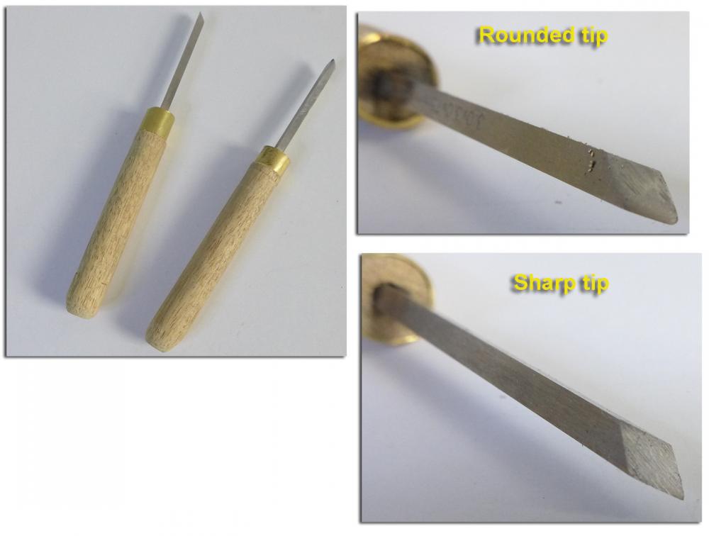
SWIVEL GUNS I really didn’t like the swivel guns supplied with the kit. At first I thought I’d just keep the kit barrels and make my own swivel mounts (which I did, earlier on in the build – see within entry #100 at http://modelshipworld.com/index.php/topic/335-hmc-sherbourne-1763-by-tkay11-–-caldercraft-–-scale-164-a-novice’s-caldercraft-sherbourne/?p=117947). I thought I wouldn’t have the skill to turn my own barrels on brass, but in the end, seeing as I bought a really cheap Taig lathe on eBay, I reckoned it would be a good opportunity to learn a new set of skills. The first step, of course, was to make the right tools for the job – notably gravers. There are some excellent tutorials on the web on how to make gravers, so I bought some 3mm square HSS lathe bars, some wooden dowel and set up a sharp pointed graver for the square cuts and a rounded graver for the smooth barrelling. I was surprised to find that with really sharp gravers, cutting into the brass was almost exactly similar to cutting into wood on a wood lathe. As a result, I was able to cut 8 barrels in a couple of days using the plans for the swivel guns from the AOTS book on the Cutter Alert. Luckily the swivel mounts I had made were exactly the right size. Something that struck me was that it would be easier to cut the handle of the swivel gun at the same time – rather than soldering on a rod at a later stage. This way I’d be able to bend the handle after heating it with a butane gas burner. It took me a little while to figure out how to cut the holes for the trunnions in such small barrels (roughly 1.5mm diameter), but I hit on the plan of making a jig from an epoxy putty (Milliput) and leaving a 0.4mm thick piece of wood on which to lay the end of the barrel so that the trunnion hole would run vertically across the barrel. Unfortunately my attempts at blackening were not great – it may be that my blackening agent is now too old), so I ended up painting them (much to the dismay of my wife who thought the brass finish was beautiful). Much as I would have liked to keep the brass finish, it wouldn’t have been in keeping with the rest of the model and the ebony barrels of the 3-pounder guns. The sad thing is that the black paint on the barrels adds a layer which blurs the sharp edges of the rings and the detail. Still, it’s probably a bit better than the kit barrels and I did learn a whole lot about turning brass with gravers! Next up: Anchors Tony

- 269 replies
-
- 8
-
-
- Caldercraft
- First build
- (and 3 more)
-
Thanks, Joel and Druxey. I am happy in following Harland as suggested by both of you. Interestingly there are a couple of ringbolts on the deck whose function was not given in the Sherbourne plans, but whose position is exactly right for the anchor tethering. Pete: eBay in the UK has lots of chain of various types. You have to specify links per inch or per cm, as well as structure (e.g. oval, stud link) and dimension (e.g. 1.5 x 1mm). There are also a few modelling shops (especially railway modelling) selling fine chain. Tony
-
I have just made the anchors for my Sherbourne, but am a little unclear as to how they would have been stowed. The AOTS book on the Alert shows the following: This is fairly similar to the plans with the kit which show the anchor stowed -- although the throats of the anchors on the Sherbourne plans are held by a rope. John Harland in his book on Seamanship in the Age of Sail also shows the anchor held by ropes. My question relates to the use of a chain as shown for the Alert. How would the chain round the throat have been fixed to the bulkhead? Presumably it can't just have been wound round itself -- or would that have been the way it was done? The question equally applies to rope fixing, because they'd need to be fixed very strongly to hold something that weighs 12cwt and is perched on the outside of the ship. I am tempted to use chain just because I have some of the appropriate size, but realise it may be inauthentic for a cutter that was some decades earlier than the Alert. Any comments on how the anchor may have been stowed, along with some details of how the ropes or chains were fixed to the bulwarks, would be very much appreciated. Thanks Tony
-
The link about the bulkheads is very interesting, Mark. I did have a look at the POB plans, but as I have POB plans of La Jacinthe, I'll probably do that instead at some stage in the future. I hadn't thought about the piracy problem, so I quite understand. As it is, now I have the complete plans, I am quite happy with rounding the dimensions to the nearest half mm in most cases. Thanks again Tony
- 132 replies
-
- 2
-
-
- triton cross-section
- cross-section
- (and 1 more)
-
It's alright, Mark, I'm not really bothered. I took the measurements straight from the PDF after loading the plan both into TurboCAD and into Adobe Photoshop. Maybe if the plans were originally made in a CAD programme, then the CAD files could be left for downloading as well. Anyway, the important, great and lovely news is that I now have access to the full set! Whoopee (and thanks, Chuck)! I'll now just get on with it as these plans have the full overall measurements, and hope that I can do as well as you have done in following this intriguing path which, at every turn I have taken so far, is endlessly challenging and interesting. I think you know it was you that gave me the idea of moving from kit to cross-section to full build, so thanks again! Tony
- 132 replies
-
- 4
-
-
- triton cross-section
- cross-section
- (and 1 more)
-
Thanks for the likes! Mark: You're quite right. It's not really a problem from the point of view of constructing the model, and of course I printed out the plans and have cut the pieces so that they have the same width and length (unless, of course, the keelson really is supposed to have a different width from the other two pieces). The only (and very trivial) reason for the comment is that I like to put the plans into CAD and then (once I have the complete set of plans) visualise the build in 3D. However, because CAD requires accurate and consistent measurement to do this (its lines have no thickness) and because the lines on the plan have a thickness of 0.38mm (or 1/4 inches at full scale) I have to make a decision as to whether I trace the lines from the outside, centre or inner edges. The convention is to take the lines from the centre. But whatever position I take on the plans as they are, the different views of each piece do not match up. For example, if I take the drawings of the keelson, the outer edges of the cross-section are 8.03mm top to bottom (and 8.18mm across), while the outer edges of its side view are 8.34mm from top to bottom. As I can cut to a tolerance of 0.1mm (on a good day and when there's no wind blowing), I am then left with a choice as to the width and height of the timber. Naturally I do make the choice, but if the all of plan sheets in addition provided the full-scale dimensions of the timber I would then be confident of matching up all the pieces for CAD purposes. I really don't want to make a mountain out of a mole hill of this issue, as in fact I know I'll be able to build the cross-section from the plans as they are because the differences are so tiny. It really is just a very, very minor comment in relation to building it up in CAD. After all, in real life these ships were made from plans that were only on paper in the first place -- and even then the builders did not necessarily follow the plans given but built according to what they had to hand and in accordance with necessities as they arose. Furthermore, it's a bit ridiculous for a novice like myself to make any sort of comment like this when I have only just started out on the process of a full scratch build (apart from the tiny ship's boat I made for the Sherbourne). Tony
- 132 replies
-
- 6
-
-
- triton cross-section
- cross-section
- (and 1 more)
-
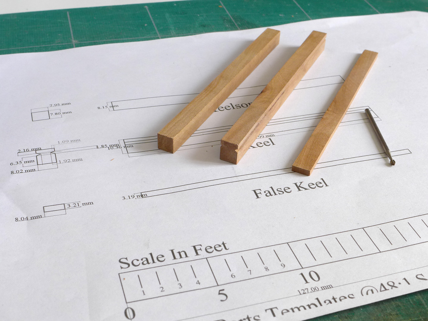
Oops! Just realised I had to start the build log to obtain the plans. So here it is. First steps at the cross-section. Cutting the lengths was really easy. The only problem was defining the dimensions as I much prefer to work from CAD and in metric -- and I don't know the original dimensions of the real timbers. So I diligently took the plans into TurboCAD and traced them. The difficulty, of course, is defining which part of the thickness of the lines to take as reference since the drawn lines are 0.38mm wide. This resulted in my having a variance of between 0.1 and 0.2mm between the different views of the keel, keelson and false keel. In the end I just decided on a particular width which seemed closest (e.g. 3.2mm for the false keel) since I reckoned the differences to be so small as not to be worth fussing about. All the same, it might be an idea for beginners like myself to have the original dimensions of the timbers shown on the plans so we can just draw them in CAD. As a result, I also thought I'd wait to see the plans in their entirety before settling on a particular set of measurements for the purposes of 3D modelling in CAD, so I can use the CAD drawings to think about the whole process. As to the rabbet, I toyed with the idea of cutting a scraper, but found that one of my milling pieces fit the profile exactly. So this did not prove a difficulty -- although I am fully aware that longer sections of keel would demand more complex curves and angles. So the following picture shows the progress thus far, and I request access to the plans if that's ok. I'm still working on the last stages of my Sherbourne (anchors and swivel guns) but want to see the Triton plans as soon as possible so that I can work out what I need and how I'll be doing it. Thanks Tony

- 132 replies
-
- 9
-
-
- triton cross-section
- cross-section
- (and 1 more)
-
Thanks Dirk, BE, Carl, Jörgen, Gunther and Mumin. The support and encouragement always stoke that nice warm glowy feeling when the efforts are appreciated. As usual, thanks to you all and so many others on this forum for the guidance I have had from your logs and notes. Tony
- 269 replies
-
- 1
-
-
- Caldercraft
- First build
- (and 3 more)
-
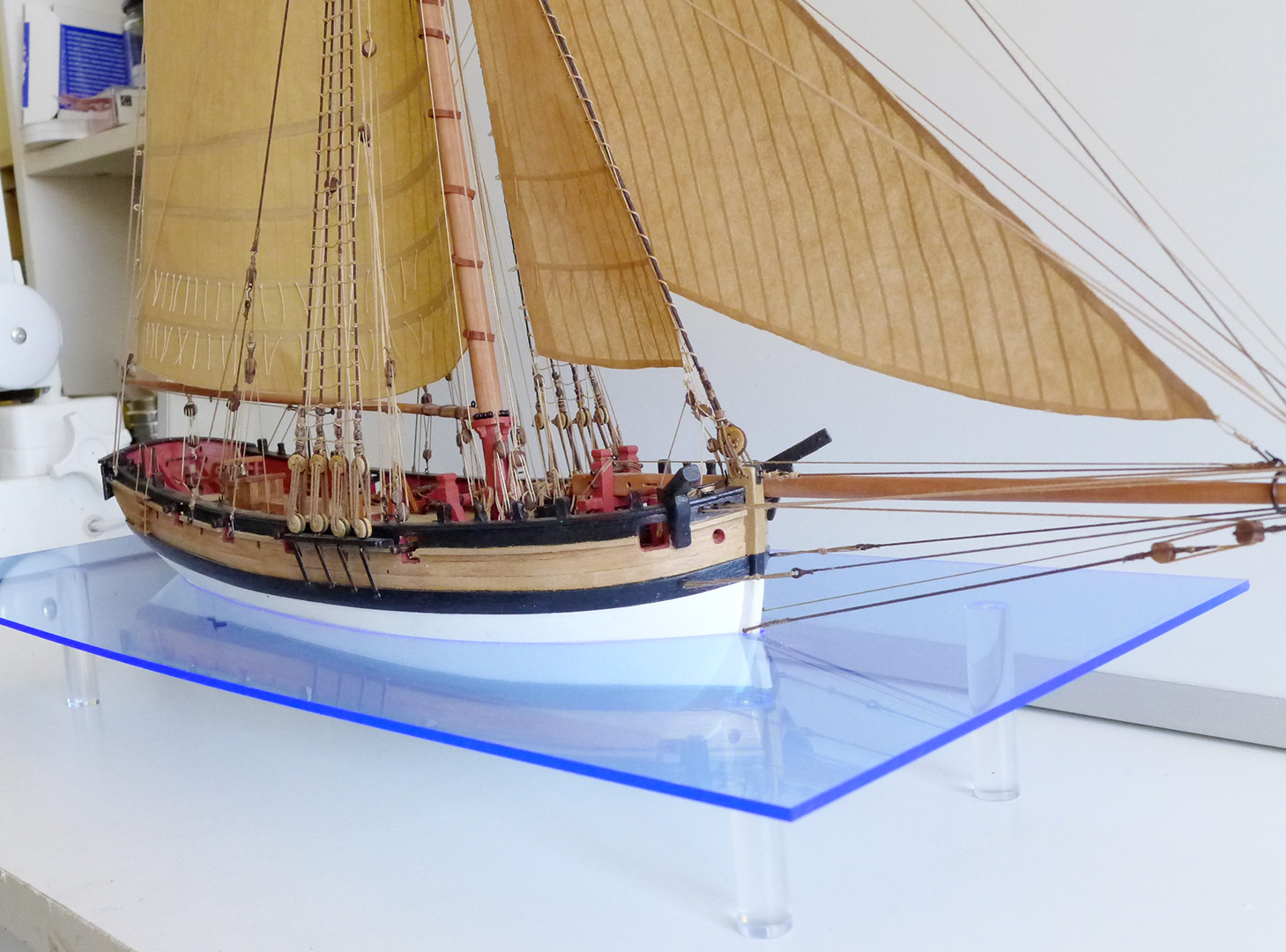
FINALISING THE BASE The A3 size blue-tinted acrylic sheet arrived, I cut it to 200mm width on my table saw using an acrylic-cutting blade, then as before cut out the shape with a coping saw. To hold the sheet I bought 300mm of 12mm acrylic rod and cut it into 51mm slices on the saw, then brought that down to 50mm with the disc sander. This ensured the cuts were smooth and the face at right angles. The ends of the cut rod were then polished using 1000 grit carborundum paper followed by a final polish with a leather strop and some honing compound. This meant that the acrylic welding solution could then be applied to the legs with a fine paintbrush – allowing the solution to be drawn into the joint by capillary action, leaving no sign of a join. The final result is as shown below. Now I’ll start work on the swivel guns as the graver’s rod has arrived. Tony

- 269 replies
-
- 16
-
-
- Caldercraft
- First build
- (and 3 more)
-
Thanks, Dirk and Dr. Per. I'd be glad to send CAD files, Dirk (if you're really serious), but the problem is that each of them has a mix of a jpeg background and CAD measurements and lines. The programme will only send the measurements and lines, but not the jpeg background. So the only thing to send that shows it all would be a pdf file. Let me know by PM if you do want such a thing. Tony
-
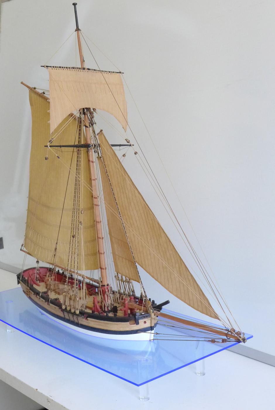
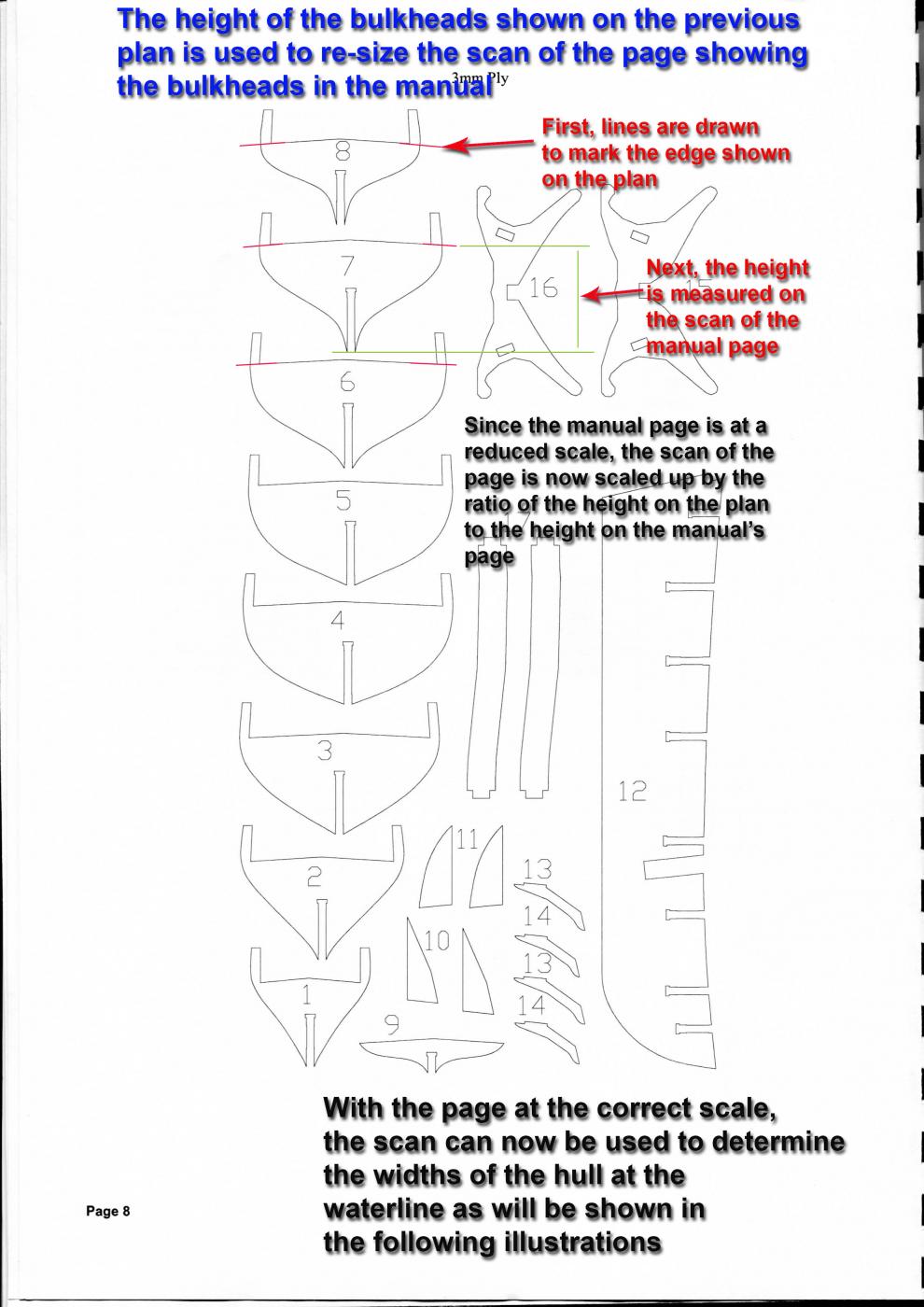
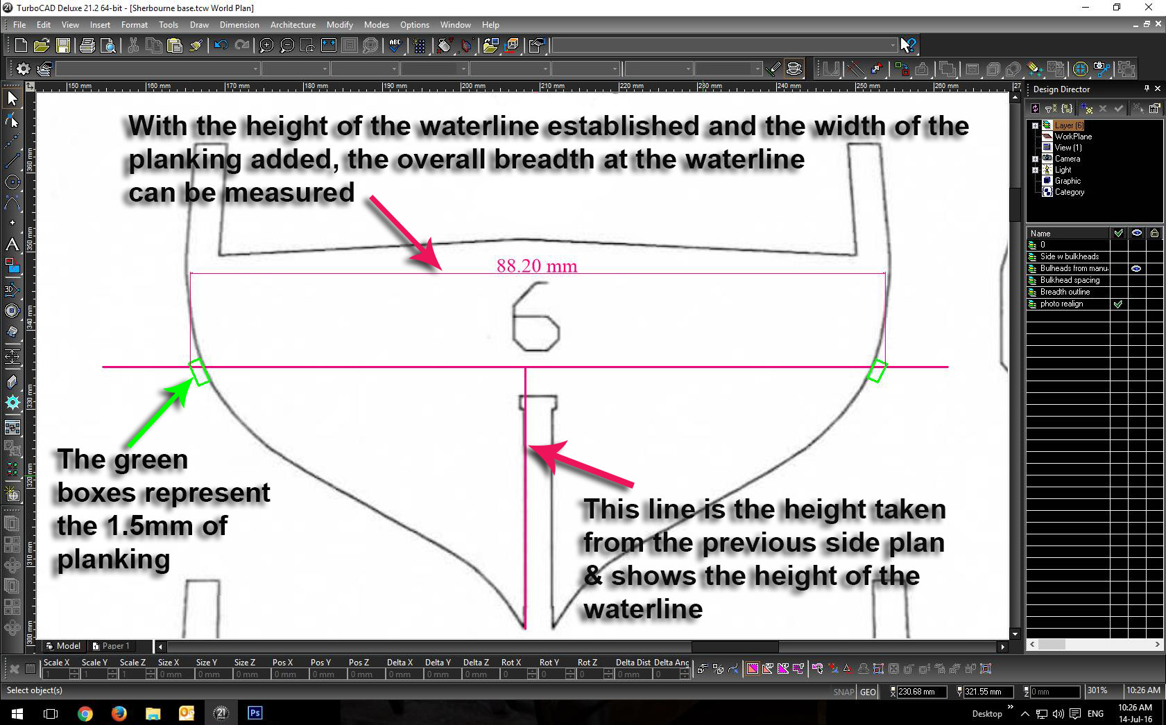
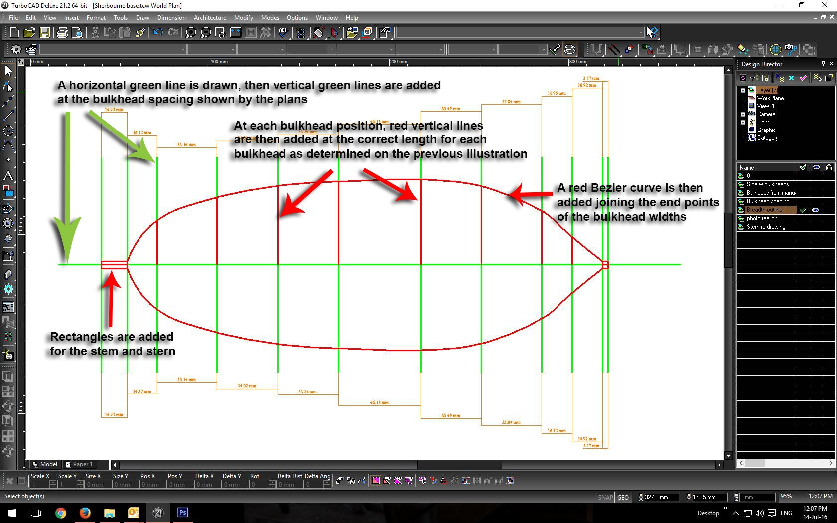
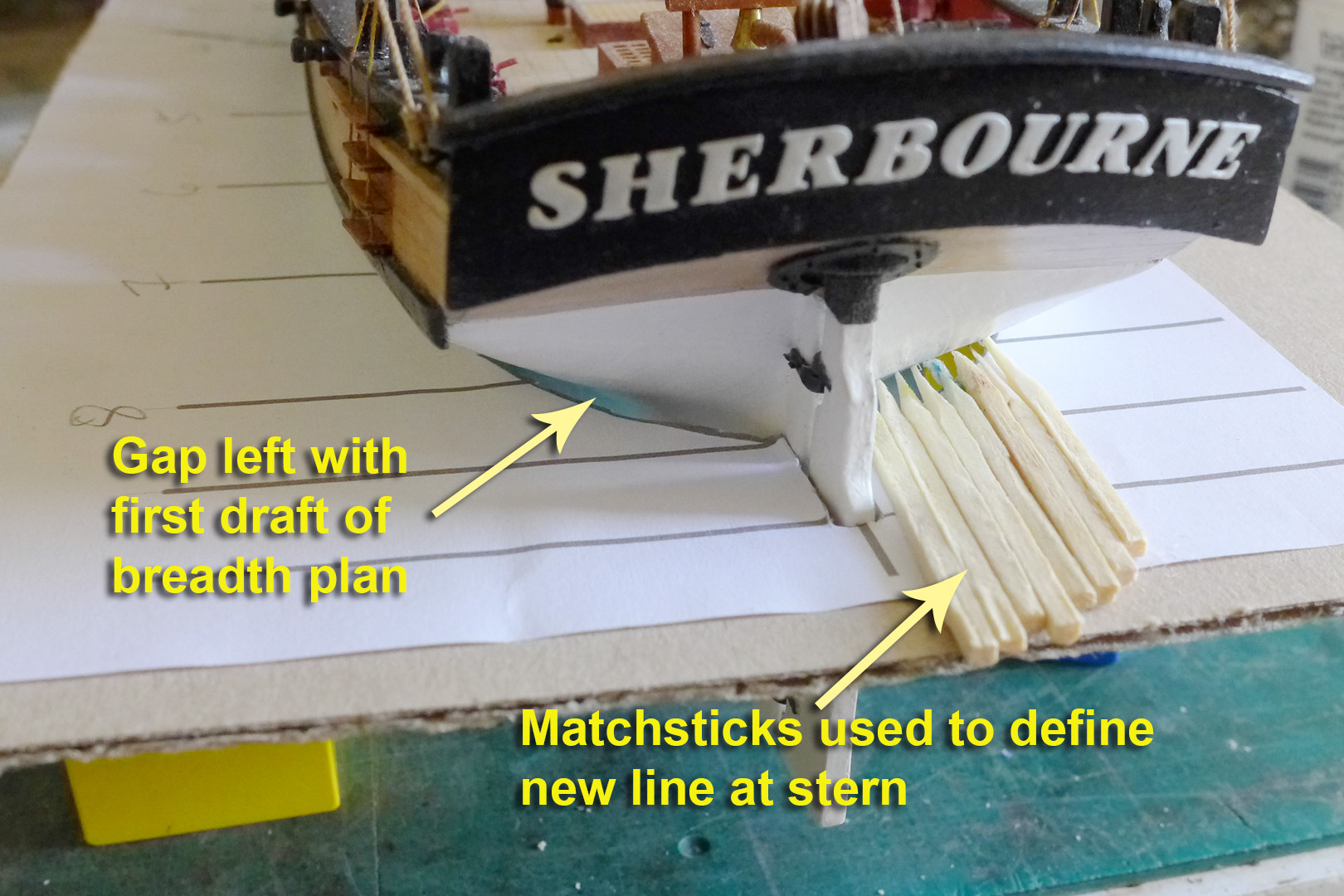
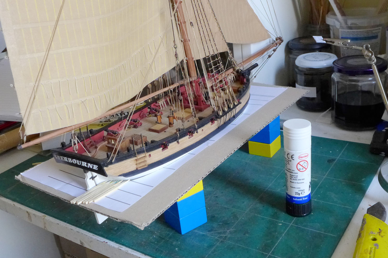
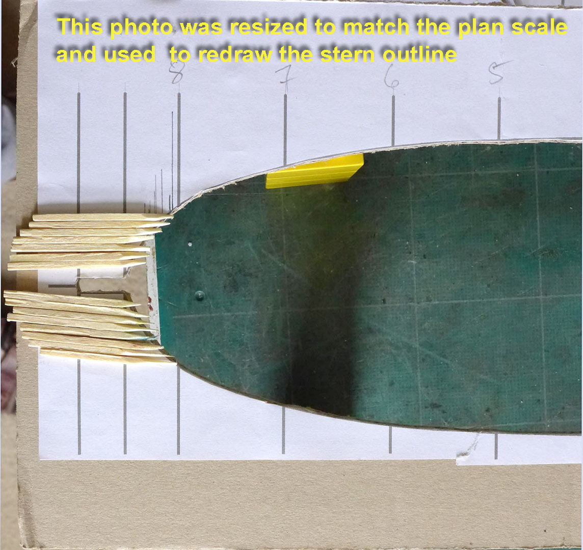
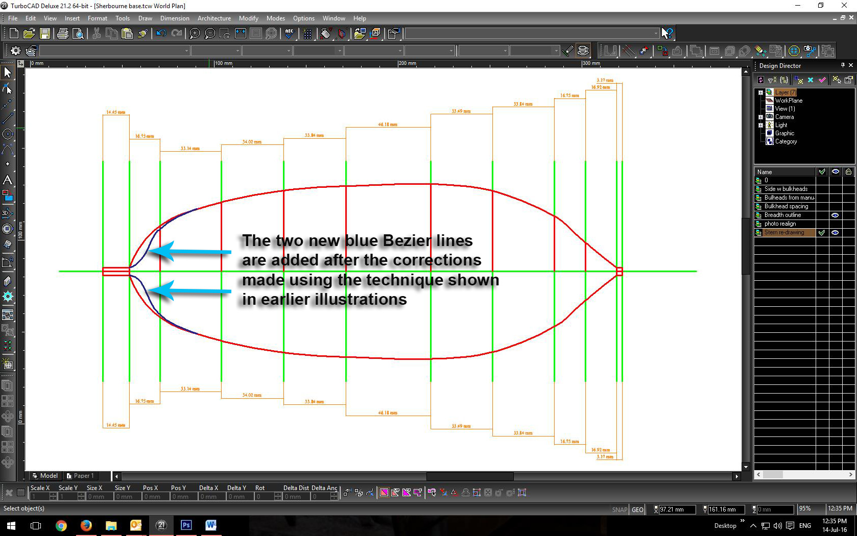
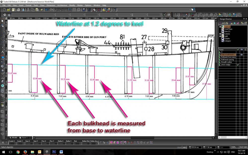
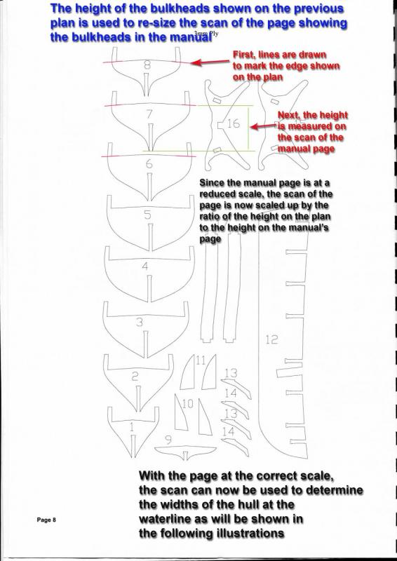
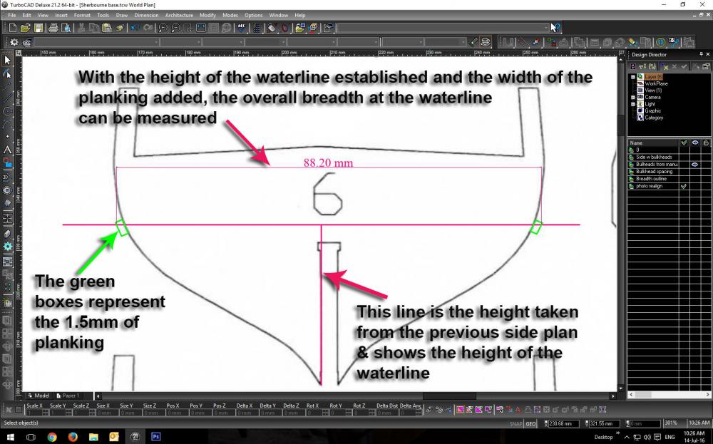
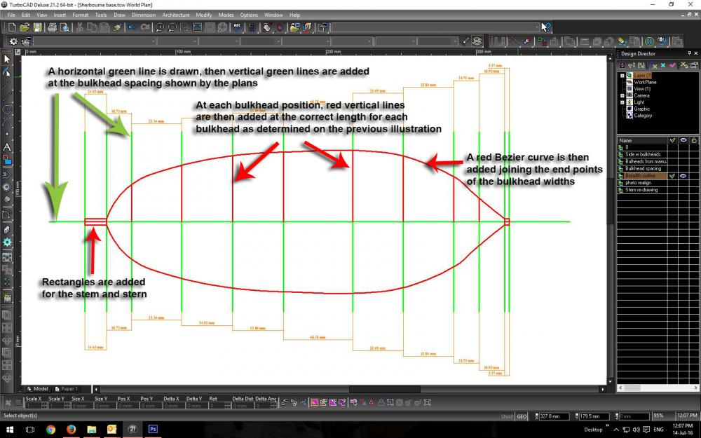
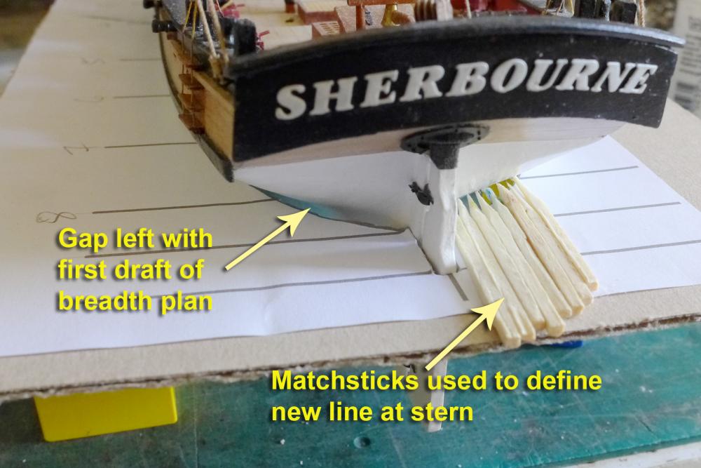
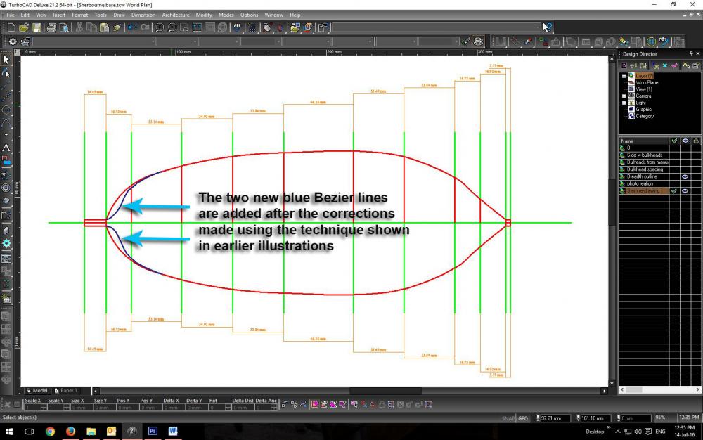
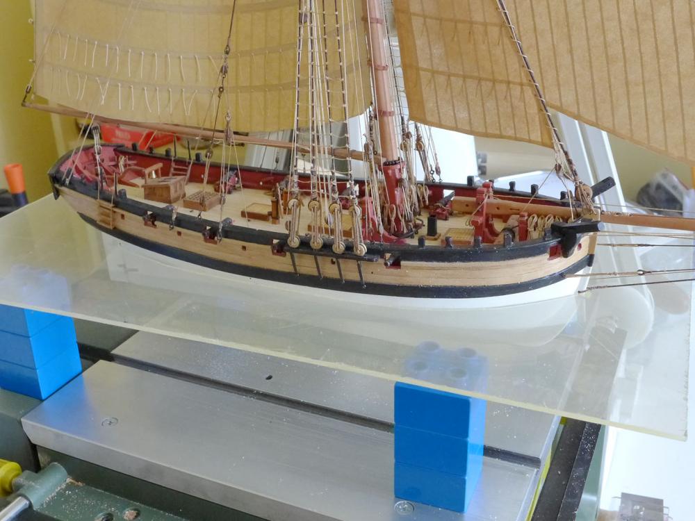
MAKING THE BASE Whilst waiting for some parts to make a graver (so that I can turn the swivel guns) I decided to think about the base. For a very long time I have wanted to make a Perspex base so that the ship could be seen as though in the sea, while at the same time being able to see the whole hull. What kept me back was how to make a plan of the breadth at the waterline since the kit plan sheets have no half breadth plans. However, after thinking about it I realised that the parts page in the manual might be usable in connection with the sheet plans since the sheet plans are exactly to scale. So I started by taking the measurements from the sheet plan of the side view. First were the keel and waterline. This allowed me to determine the angle of the waterline which is 1.2 degrees (but which knowledge doesn’t really figure in the ensuing work). At each bulkhead, I was then able to determine the distance from the waterline to the base of the bulkhead. With this knowledge, I could then take the page on the manual and re-size it so that the bulkhead outlines were at the same scale as on the sheet plan. This was done by marking the edges of the bulkheads and then measuring the distance from the base to the edge of the bulkhead. The ratio of this height to the height on the sheet plan gave the ratio for re-sizing. I could then take the re-sized bulkhead drawings and, after adding a 1.5mm thickness to each side for the planking, determine the full width of the hull at the waterline for each bulkhead. The measurements of the distances between each bulkhead and the width at the waterline allowed me to calculate a half-breadth plan and therefore an outline of the shape to be cut. I pasted the plan to cardboard, cut the outline, and placed the ship in it. This showed where the outline deviated from the model. Amazingly the only significant difference was at the stern. In order to compensate for the gap and draw a final outline, I glued matchsticks to the form with their ends touching the hull. I then photographed the outline and resized the photograph to the same scale as the plan. This allowed me to draw a new set of Bezier curves to make a final outline. As I have never cut Perspex before, I used an old sheet of the stuff I found on the road near my home and practised cutting and drilling it. It was simpler than I thought. All I used was a hand drill and a coping saw (other than the table saw to cut out a rectangle). I glued the plan to the sheet with a water-based glue so that after cutting out the panel I could simply wash off the plan. The current status (while I’m waiting for some tinted Perspex and the various fittings to make the final version) is as follows. Please note this is only the first attempt and the Perspex is dirty, cracked and scuffed – as you might expect from its having lain on the roadside! I'll post later once I have made a final version of the base, but thought you might be interested in progress so far. Tony


- 269 replies
-
- 8
-
-
- Caldercraft
- First build
- (and 3 more)
-
Sorry, Patrick, but I don't have any photos and can't remember how I did it. You can see from the first posts on my log that I had put the nuts in before the keel, but that I made a mess of the keel when drilling through. I seem to remember that I turned the hull upside down until the keel was level and held it in place with stuffing underneath as well as on the side whilst I drilled down using a set square as a guide. You can always drop it as an option and just go back to mounting it with the kit stand or another method. Some people just make it look like a shipyard and used beams held up against the side. There's no shame in retreating if you want to retain your sanity! Tony
- 69 replies
-
- 2
-
-
- lady nelson
- victory models
- (and 1 more)
-
Thanks, Jörgen. Your start and your craftmanship are already better than mine, and I'm sure many of us are looking forward to seeing your decisions along the way. Every Sherbourne I've seen has a lot different about it -- and it's always interesting. Tony
- 269 replies
-
- 1
-
-
- Caldercraft
- First build
- (and 3 more)
-
It is really difficult to drill the holes after you have placed the keel on the hull if you want accurate alignment since the nuts have to be placed correctly within the hull -- at least this is what I found when I was doing the same kind of thing. I don't know whether this applies to the mounts you bought, so in your case it may be easier. I had to figure out a jig that would allow me to drill through the keel with a precise vertical alignment. Of course it would have been much easier if I had drilled the holes in the keel before fixing it to the hull -- another one of the reasons why a lot of modellers wait before putting the stem, keel and sternpost on! Tony
-
Great to have another Sherbourne! I really like the approach you are taking and will follow with great interest. All these various builds (including Chuck's Cheerful) have shown an evolution in the way these cutters are approached. By the way, I was at first puzzled by your post #4 where you say "I also excrement with dowels". It took me just a little time to realise you meant 'experiment with dowels'. I am sure most other readers will understand immediately, but thought I'd point it out just in case others puzzle over it as well. Tony
-
Attaching a Cutter's foresail to its horse rail
tkay11 replied to tkay11's topic in Masting, rigging and sails
Thanks for the clarification, Roger. My misreading! I'm not a sailor, except for my desk chair, so I am totally useless at saying anything of value here! Tony -
Attaching a Cutter's foresail to its horse rail
tkay11 replied to tkay11's topic in Masting, rigging and sails
OK, Roger, I see it now, but the section in question is to do with the boom/main sheet and not the stay sail -- which is what I originally raised the question about. Tony -
Attaching a Cutter's foresail to its horse rail
tkay11 replied to tkay11's topic in Masting, rigging and sails
Thanks, Roger. I hadn't seen that other idea. Sounds good. Whereabouts in Steel is that mentioned? It's too late for me to change my model now as I'm just finishing it off and want to move on, but I'd be really interested for future reference. Tony