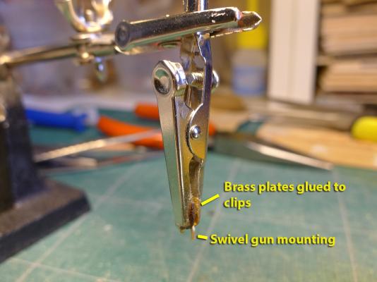
HOLIDAY DONATION DRIVE - SUPPORT MSW - DO YOUR PART TO KEEP THIS GREAT FORUM GOING! (Only 24 donations so far out of 49,000 members - C'mon guys!)
×


tkay11
-
Posts
1,827 -
Joined
-
Last visited
Content Type
Profiles
Forums
Gallery
Events
Everything posted by tkay11
-
 Very nice, Duff. Many thanks! Tony
 -
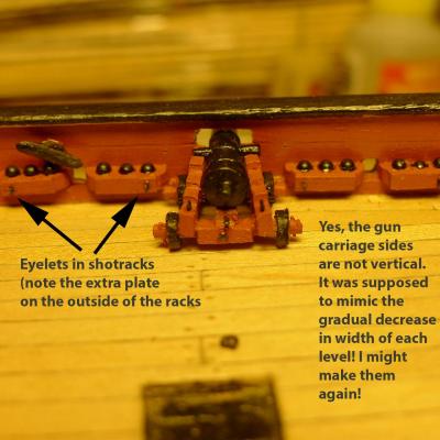
That's great, Greg. It really is a nice kit and I've been helped greatly by all the expertise here (especially by those who have kit-bashed the Sherbourne) as well as by George Bandurek's 'Super-Detailing the Cutter Sherbourne' (which I bought from Model Dockyard), the Anatomy of the Ship book on the Cutter Alert, and the wonderful hints and tips on Hubert's web site 'Wooden Ship Modeling for Dummies'. We're really flourishing now with the Sherbournes. I noticed you were on MSW1.0 before but can't remember if you had a build going. Looking forward to your new log -- which looks as though it's going to start at around the same time as hollander's. I'm sitting here in Northern Nigeria planning how to re-do the 3-pounder guns when I get back at the end of the month as I now realise I mis-read the plans for them terribly (I thought the sides raked inwards vertically as well as horizontally because I hadn't realised that the drawings in the AOTS Alert were perspective drawings rather than the plans I thought they were!). Tony
-
Thanks a lot, hollander. Welcome to the little Sherbourne fleet we are building! It's always great to have another person to contribute to the builds as everyone has a distinctive approach and brings different ideas to this lovely little cutter. I am certainly looking forward to your log when you begin your build, as many others will be, I am sure. You will have noticed how friendly everyone is on the forum, so as you get on with your build you can look forward to lots of helpful comments and support as well as to people responding to the ideas and experience you bring -- from whatever aspect. I notice you say in your other post that you are not so new to modelling, so it will be nice to hear of that experience. It has been said many times on the forum that there's no such thing as a stupid question, so don't be afraid to ask about anything over which you are puzzled. Every builder here has been, at some stage, through the process of learning and even the most experienced tell us frequently that they love this hobby because they continue to learn. If you also want suggestions about books and other sites that we have found helpful, don't forget to ask about these as well -- though it may be that you have already done enough research of your own in this regard. Tony
-
Full 3D animated build
tkay11 replied to pompey2's topic in CAD and 3D Modelling/Drafting Plans with Software
Thanks for the link, Nick. I think this was on MSW1 as well so it's great to have the link back again. There's another spectacular build of the cutter Alert which was discussed on this forum at http://modelshipworld.com/index.php?/topic/365-an-unusual-build-log-for-the-cutter-alert/?p=3556. However I've just checked and the build itself now seems to have moved to http://sketchucation.com/forums/viewtopic.php?f=333&t=33757. As far as I can remember there were a few comments on the 'Belle' build concerning the gunport lids opening sideways and the way the planking was laid on the keel (look at the garboard and the next plank up) but the fact is this is a wonderful way to do the builds and I am amazed at the skills of the builders of these models (i.e. such as those on this forum who are doing 3D builds such as the Panthere and Pandora). Tony -
Thanks, Nigel for the clarification and to JM Pett for the advice about speeds. It does sound as though the Proxxon MF 70 is the way to go as so many on this forum use it happily. I'll still wait to find out more about using my Proxxon Micromot 50/E in the MB 200 drill stand as the stand is advertised as allowing milling work with the mini-drill but I can't see how it allows for fine vertical adjustment as there are no manuals available online for this particular stand. Tony
-
Thanks, Nigel. I am sending a pm to MIJ as suggested. Tony
-
One of the things I've been considering is to continue with my Proxxon Micromot 50/E (5,000rpm- 20,000) but to add a Proxxon MB 200 drill stand and the KT 70 table. The mill MF 70 has exactly the same speed range (albeit with a higher power of 100W) but I'm still trying to find out if the MB 200 drill stand can really be used with fine vertical adjustment as a milling device. Does anyone have any knowledge of this combination? Am I right in thinking that speeds of 20,000 rpm suit milling wood with small mills (about 1mm diam) very well? Tony
-
Looking forward to the photos! Tony
-
Thanks, B.E. One of the great pleasures of this hobby is working out how to mimic a particular part at scale. Perhaps I should also have shown the failed earlier attempts at swivel mountings. Now you say it, I remember a discussion from MSW1 saying that not all the swivel mounts had guns. Can't remember who said it or in what context. It certainly adds to Kester's logic concerning the crowding of the swivels. Gregor: no problem at all. To my mind a build log is there exactly for this kind of purpose -- to explore the possibilities, problems and interest of the particular model ship we try to build. As a result others who build the same ship have an opportunity to benefit from, laugh at or contribute to the discussion. The builder's a kind of facilitator who prompts the discussion by showing his/her progress, thoughts and methods. This facilitator also benefits hugely as a result. I'm in the very lucky position of still being able to modify a lot of my model in line with the experience of others as I've assembled hatches, blocks, rings, cannon and bitts but not stuck them on yet (only the shot racks might be a problem to remove). So please, always, feel free to to cross-talk. And I'm grateful for your open invitation on your build as well -- should I ever be in the unlikely position of having something new to contribute! I'm now ensconced in Northern Nigeria for three weeks of planning meetings, so I'll be well away from modelling for the moment but will be reading the forum regularly (as long as the internet connections stay up, that is). Thanks very much for all the continued support! Tony
- 269 replies
-
- 1
-

-
- Caldercraft
- First build
- (and 3 more)
-
Thanks, Kester. As you know, you were the inspiration for the jeer bits, so I have to thank you for that as well! Yes, I might well reduce the number of swivel guns as you have done. I've had a good look at yours and agree it gives more space for the gunners. I'll always be happy to opt out of the arms race. Tony
- 269 replies
-
- 1
-
-
- Caldercraft
- First build
- (and 3 more)
-
Thanks, Jay and Gregor. Gregor: I must admit to being quite dissatisfied by my attempts at the shot racks. I've just had a look at your new post on this and yours are much better. I was intrigued by the fact that you have managed the issue with the oar ports quite easily, so I'll take a few of your ideas and see if I can dismantle mine. The problem is that my shot racks are all glued in with epoxy. I also do agree with your shortening of the sliding hatch. I had not taken in the fact that the Alert is a bigger ship than the Sherbourne. Luckily, that hatch is not yet fixed so I can remake it quite easily. Then, looking at my cannon I've been thinking of doing them all over again. I think that's part of the problem of being a member of a forum such as this where constant exposure to the wonderful skills some have hides the fact that they too went through similar learning experiences. The motto has to be 'practice makes perfect' -- or at least a bit better. Glad you like the jeer bitts, though! I really did enjoy improving my silver-soldering skills with them and the swivel guns. Tony
- 269 replies
-
- 1
-
-
- Caldercraft
- First build
- (and 3 more)
-
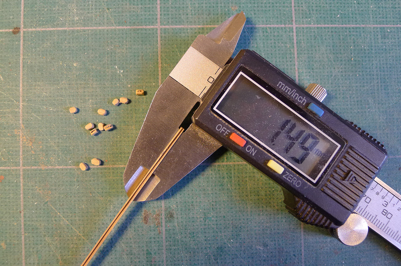
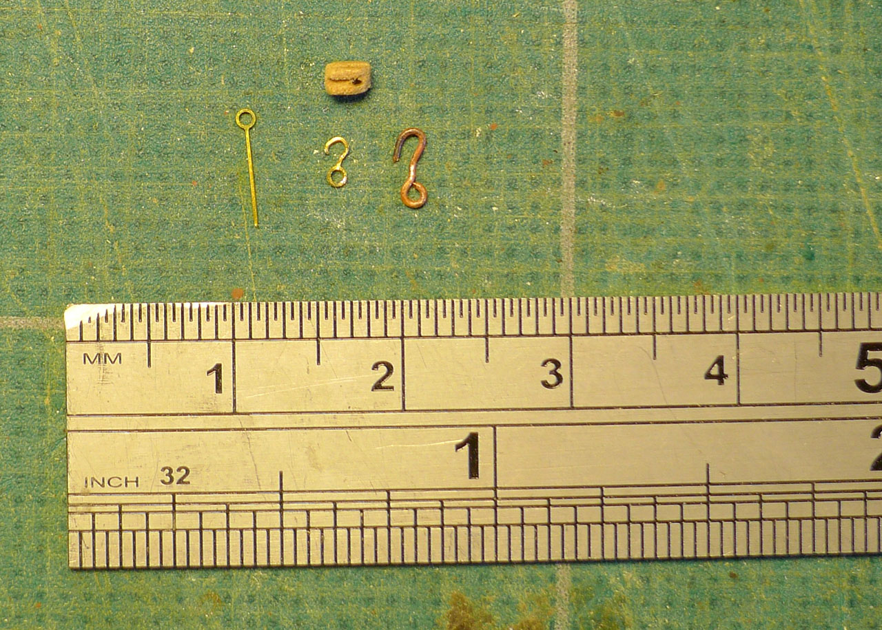
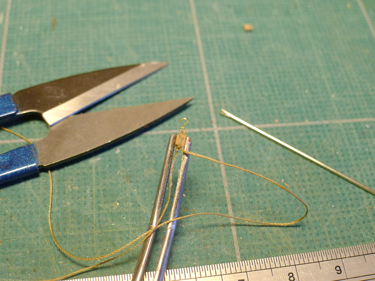
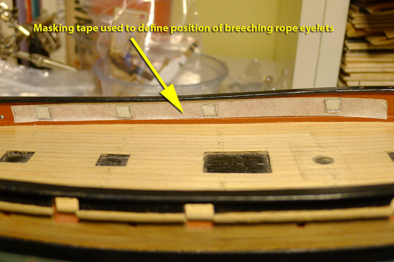
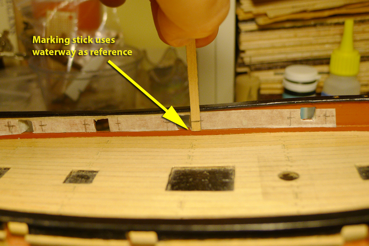
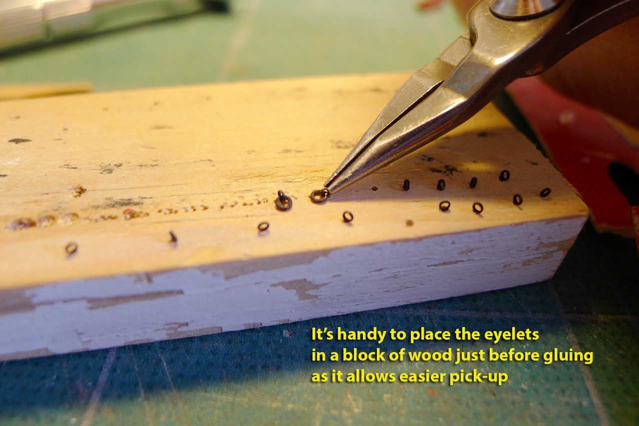
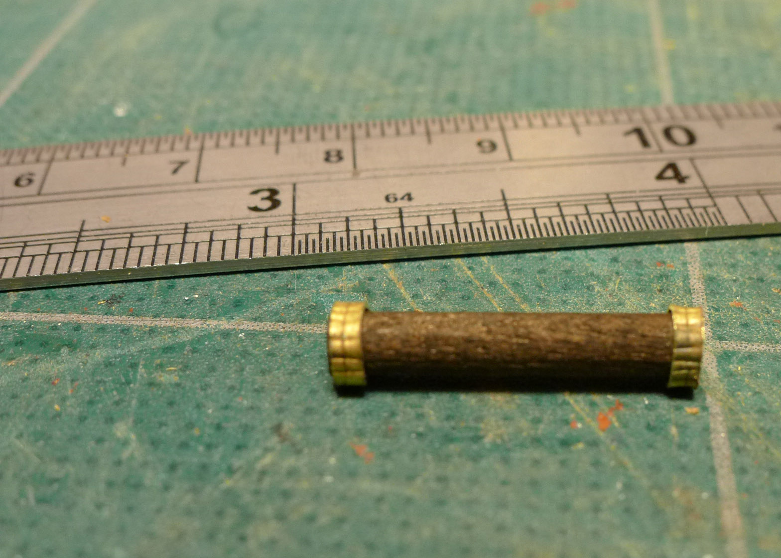
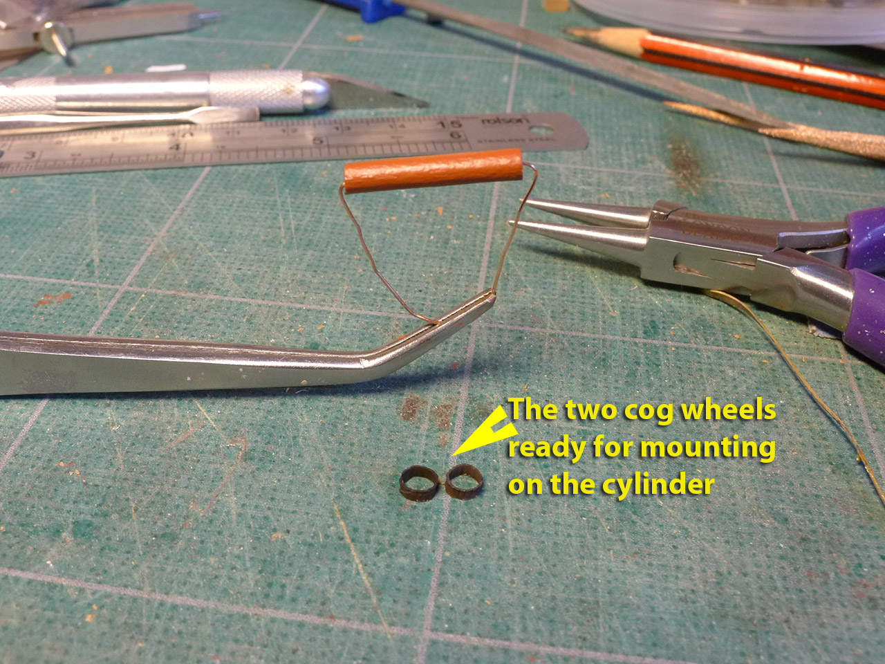
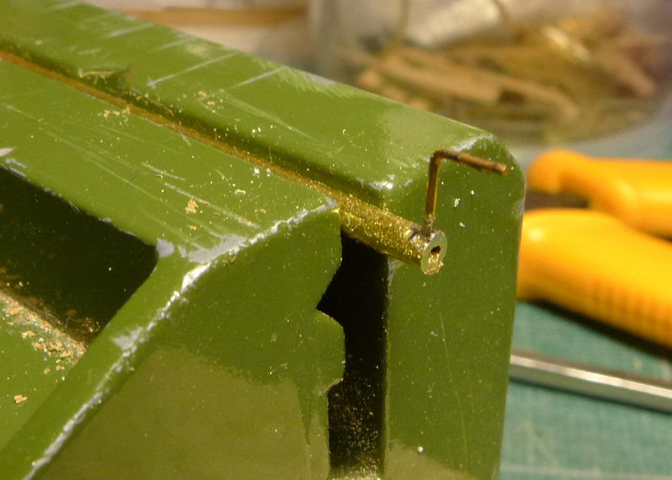
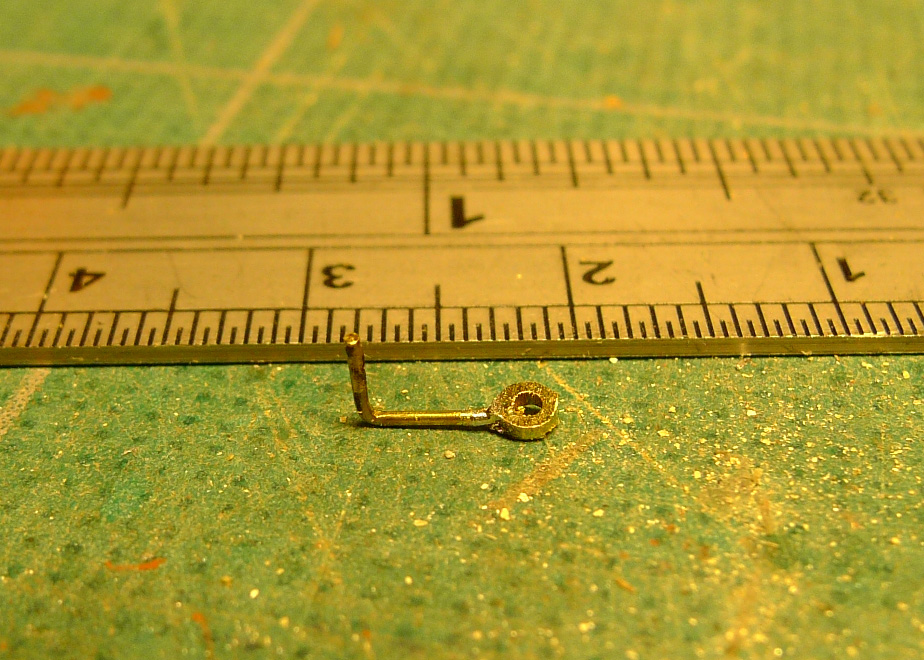
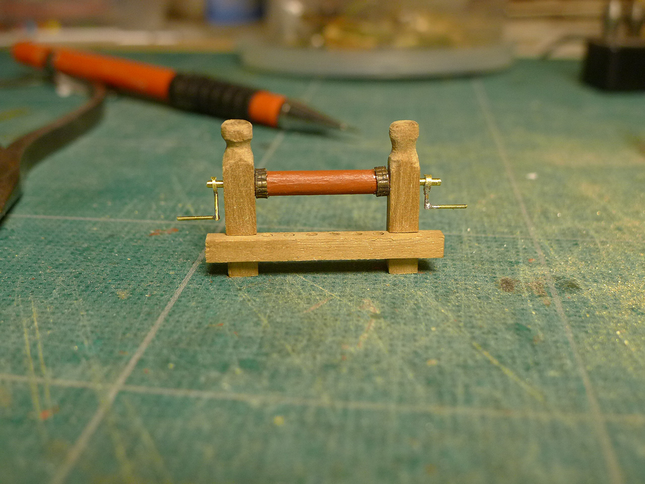
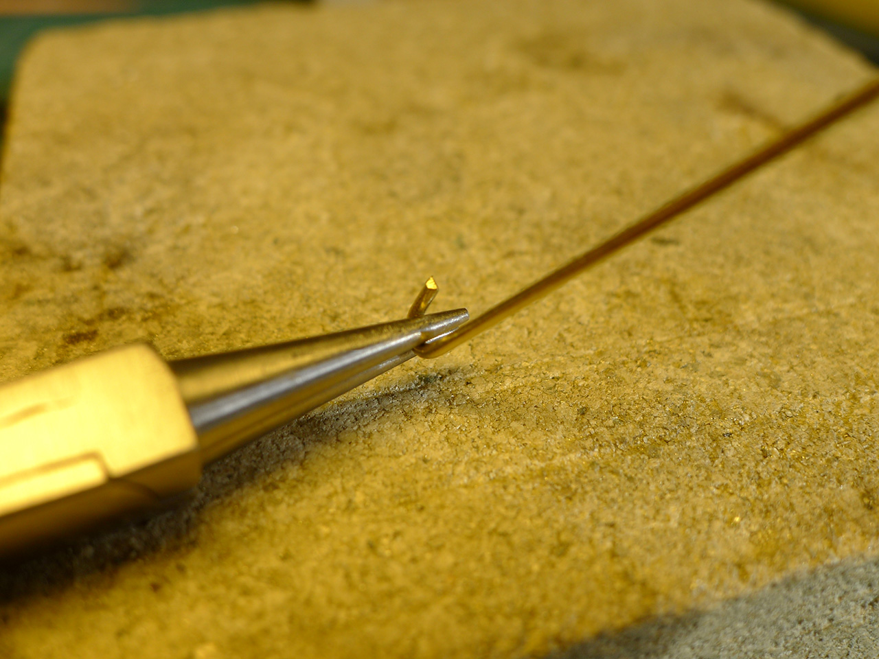
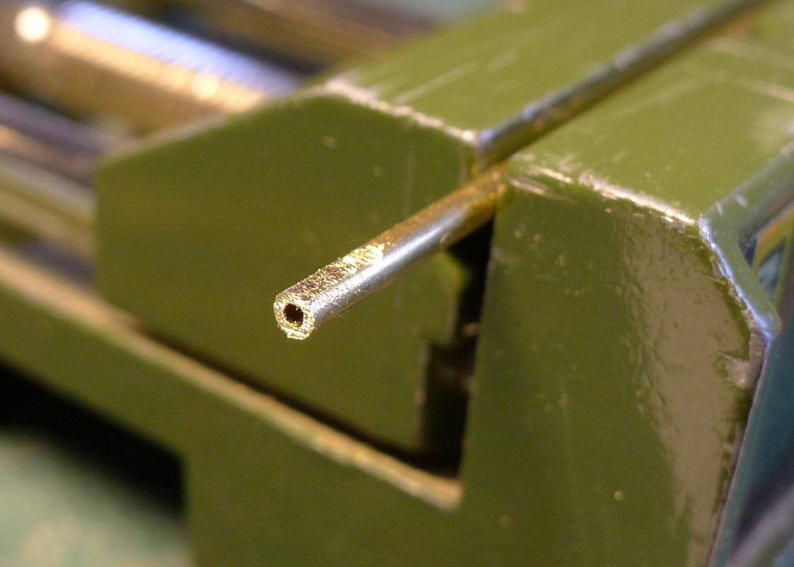
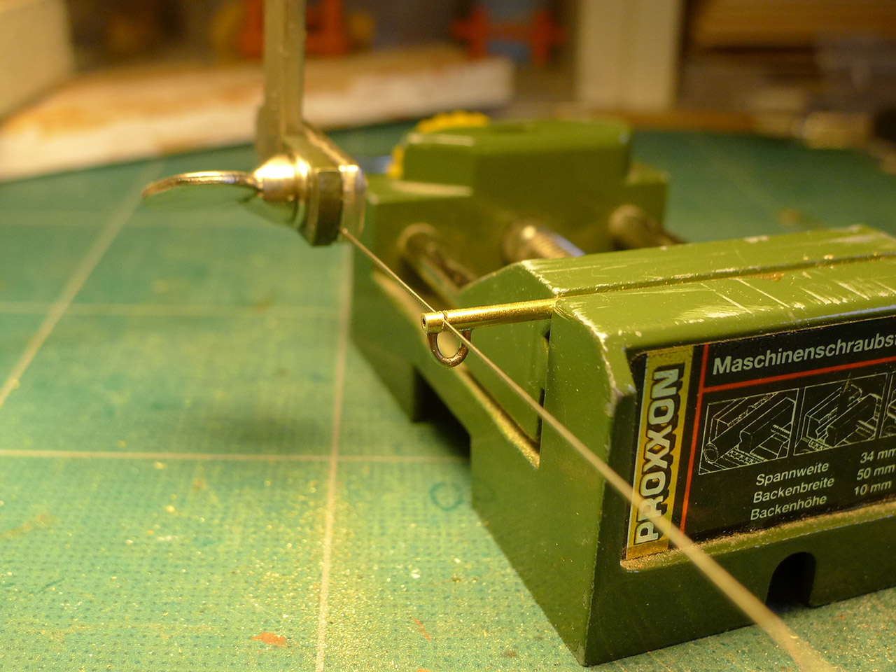
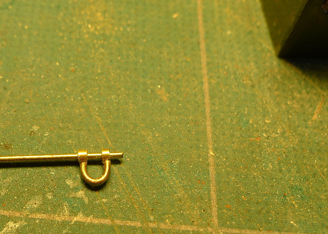
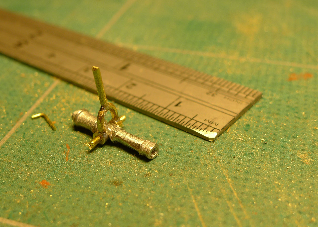
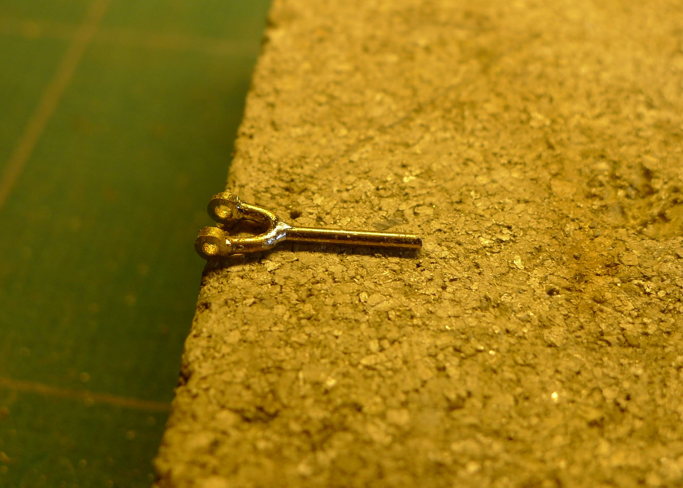
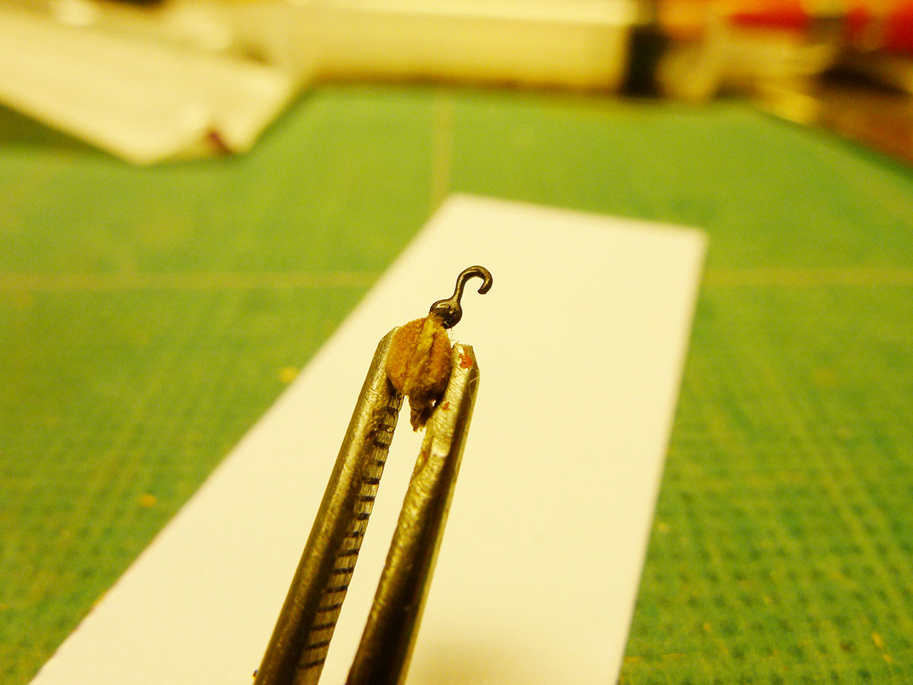
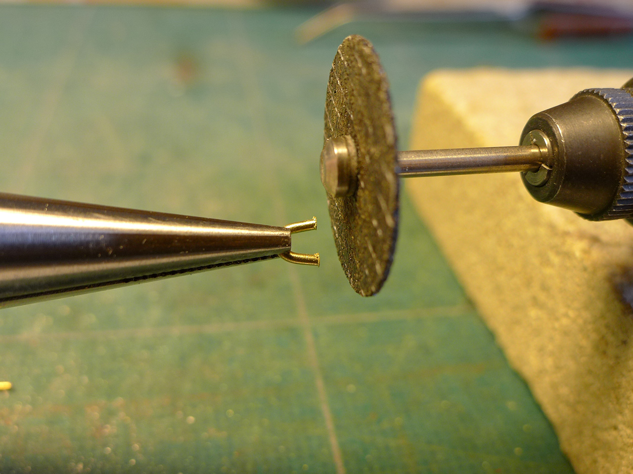
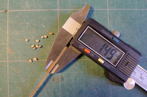
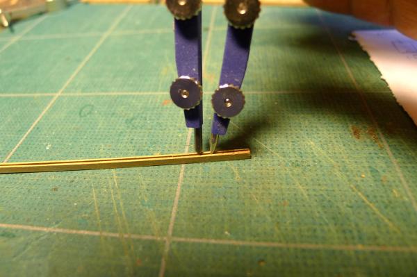
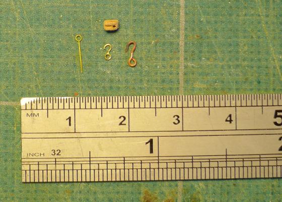
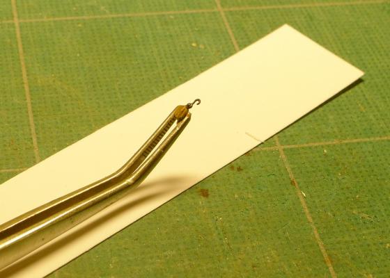
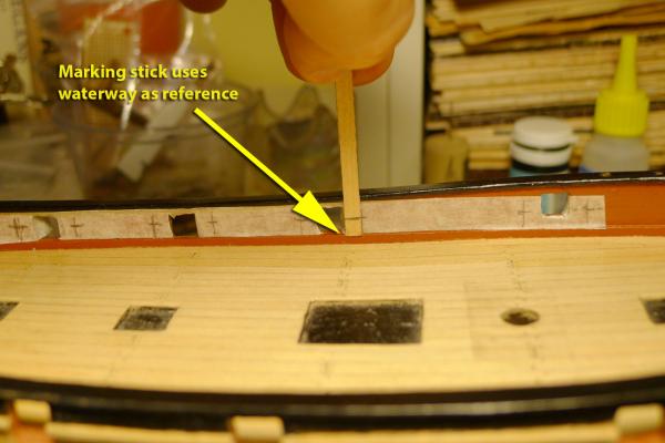
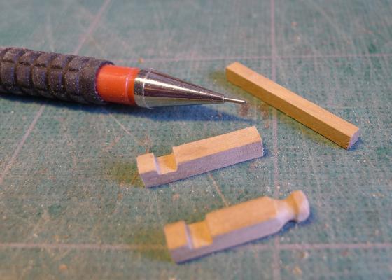
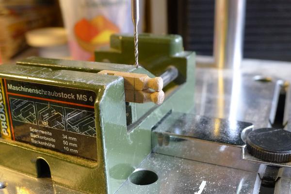
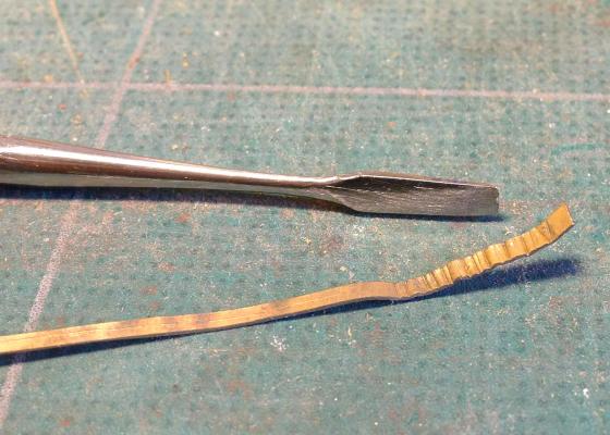
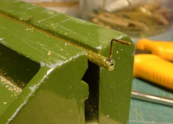
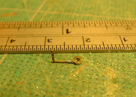
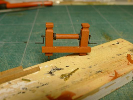
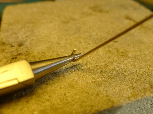
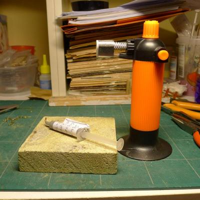
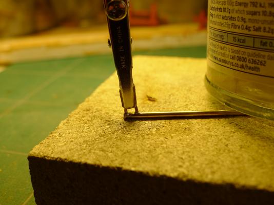
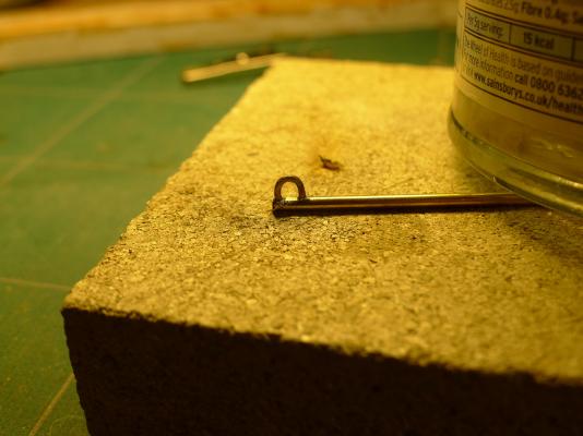
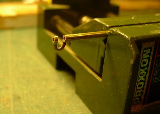
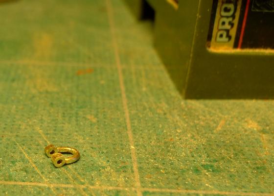
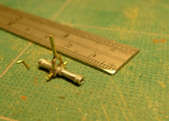
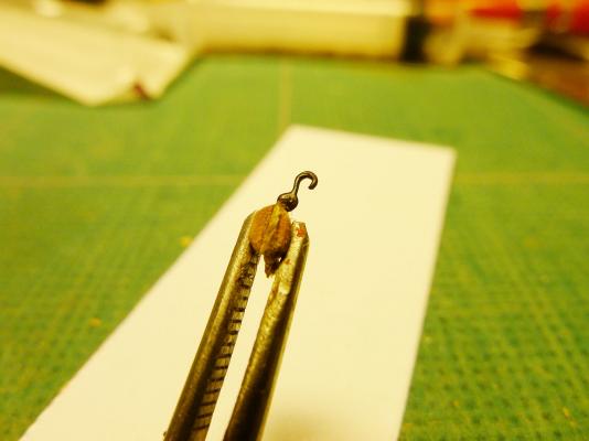
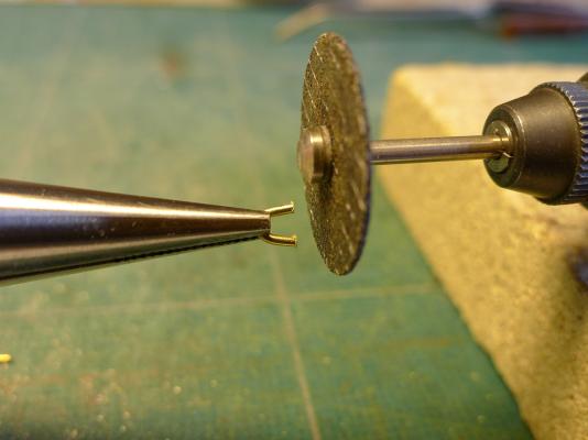
Nice to get back to modelling after such a long break. I have 4 sets of activities to report on this month, not all of them as successful as I would wish, but lots of learning resulting – as one would wish. Single blocks and stropping I continued learning how to make blocks by focusing on the single blocks and preparing hooks and stropping for them (these ones, like the doubles I have made, are for the 3pdr cannon). First off, continuing to develop skills with the table saw, I cut a groove in a 1.5mm strip of wood, marked off the block lengths using a compass, and sliced off the blocks using my Proxxon Mini-Drill with mini saw as before. I then thought how to make the hooks. First attempt was to do so by making one from 0.5mm wire. Not too good. So I used the 0.3mm etched eyelets I had bought – the eyelet will hold the rope and the remainder will make the hook. After blackening I thought the result was acceptable. Of course, the hooks didn’t have eyelets in reality, but after several attempts at attaching a hook to a 2mm block I simply gave up. Eyelets for breeching and shot racks I then marked the bulwarks to accept the top ropes for the cannon. This was done by putting a strip of masking tape along the side, breaking through gunports, and using a marking stick to determine the height of the holes. I am leaving putting the eyelets into the bulwarks until I have the tackle ready. The lower eyelets I determined to place in the shot racks. This proved to be my undoing as I clearly over-reached myself and created some very messy shot racks (it’s here that I yearned for a mill with a table as that would have allowed me to make the spacing for the shot very even, and the shot racks themselves consistent). I decided not to dismantle the shot racks and start all over again and live with the knowledge that I’ll have to do better next time. First off the eyelets to go into the shot racks. These are then attached to the shot racks. You’ll notice I put an extra board on the face of the shot racks. I took this idea from the AOTS book of the Cutter Alert which shows just this arrangement. I presumed that it was to give extra strength to the bolt holding the eyelet. Another point to notice is that whereas on the Alert the shot racks are shown unbroken between the guns, if I had done this on the Sherbourne there would have been no way of getting the oars through the oar ports. That's why they are broken up in this way, with three shot on either side of each gun. Jeer bitts Following Stockholm Tar’s lead, I decided to embark on making jeer bitts. Probably just for the challenge. I still haven’t a clue how all the rigging is going to be attached, but I thought I’d make the jeer bitts as I suppose the jeer is there to help raise and lower yards. If anyone wants to put me right on this, please do! I used the plans for the jeer bitts from the AOTS book on the cutter Alert. I started by cutting 4mm square lengths from old bits from the kit. Then I drilled a 1mm hole to hold the rotating cylinder. To make the cogs at either end of the cylinder, I cut a 1mm strip of brass and hammered a chisel into it at regular intervals. I then made a cylinder from the strip by folding it so that the chiselled edge was outwards. Well, it’s not very cog-like but at least it gives a rough idea! I painted the cylinder red ochre, as most of the deck fittings will be painted. The crank handles were made from 2mm brass tubing (which holds 1mm brass rod). This was to hold the rod which goes through the cylinder. To do this two lengths of 0.5mm brass rod were silver-soldered together to make the handle, and this assembly was in turn silver soldered to the tubing. The tubing was then sliced off with a jeweller’s saw. You’ll notice from the final picture that I remade the bitts so that the tops were square. The earlier version had rounded tops which I made as a result of mistaken interpretation of the drawings. Swivel Guns As have many others, I really didn’t like the swivel guns in the kit. However once the cascabel at the end was cut off they are at least the right length. So I decided to modify the barrels by removing the trunions, drilling out a 1mm hold to hold new brass trunnions, drilling holes in the barrel mouths to at least make them look as though they could have shot put into them, and making a small handle at the rear for the gunner to operate them. To start with I made the swivel mountings by bending 1mm brass rod round the tip of round-nosed pliers. I then made sure the mounting would lie flat by holding it against the cutting disk of my Proxxon Mini-Drill. That 2mm brass tubing then was filed flat on one surface, and the swivel mounting silver-soldered to it. In order to hold the mounting firmly to the rod I modified an alligator clip by filing down the teeth and mounting two brass plates to the sides with epoxy adhesive. By the way, for silver soldering I use a lovely little self-lighting butane gas torch that was only £5 at a local store. I had previously used a pencil torch that had to be lit with a match or a candle every time and held only enough for one piece of soldering. That's it for now. With luck I'll be able to do some more modelling in late December. Tony [PS edit: I don't know why there's this extra shot added to my post below. It says it's a thumbnail, but I don't know how to edit it out!]


- 269 replies
-
- 7
-
-
- Caldercraft
- First build
- (and 3 more)
-
Ropewalk Scale Rope Making Tool by ME - opinions?
tkay11 replied to rtropp's topic in Modeling tools and Workshop Equipment
Yes, I know the model. I have a full pdf set of the plans for it as I had briefly thought of making it myself. However it would have taken up too much desk space for my needs, So I went for doing the very simple vertical shaver-based rope walk. A slight advantage of the vertical one to the one in your plans is that it is not rigid -- the rope can shorten as it is formed. On small distances such as on the rigid horizontal one it probably doesn't make much difference (it doesn't need a weight as it is rigid), but if you were to make longer rope it might be. I simply don't know. The other thing about the hand cranked version is that when I started thinking how to build it I thought it more fiddly to get accurate with the positioning of the metal wire handles. With the shaver the whole question of having three rotating heads perfectly in sync and aligned obviously does not arise. However the speed is constant with the shaver so I can't adjust the tension. As with all ropewalks there is also a learning curve for how much weight to apply, what types of thread to use and so on. For my purposes, being a real novice, I am quite content with the rope I'm making at the moment, and don't care at all if it is right-handed or left-handed. I'm just pleased that I can make anything at all! Of course, once I'm more experienced I might become a lot more picky! I know that people have made very satisfactory rope with the rigid construction you are thinking of, so, as always, the thing is to try it out and see how it goes. If it doesn't give you satisfaction you can always try something else and you won't have wasted a lot of money. Tony -
Ropewalk Scale Rope Making Tool by ME - opinions?
tkay11 replied to rtropp's topic in Modeling tools and Workshop Equipment
Before you give up on making one, have a look at Janos' vertical ropewalk made from a shaver at http://modelshipworld.com/index.php?/topic/999-good-ol-rope-climb/?p=15887. His is a bit more complex than mine, but he shows the details. If you want to look at the one I did, it's at http://modelshipworld.com/index.php?/topic/335-hmc-sherbourne-by-tkay11-–-caldercraft-–-scale-164-1763-a-novice’s-caldercraft-sherbourne/?p=3352. There's also a nice video on YouTube showing a horizontal ropewalk in action. This one is very similar to the simple one you've already seen, but powered with an electric drill. It's at http://www.youtube.com/watch?v=024aWbB2fwE&feature=fvwrel. It's a pity that most of the very cheaply made ropewalks that used to be on the site were lost and not restored after the crash. They really are very simple to make and if you're not going to make much it's not really worth spending money on one -- as others have already suggested. Tony -
There's a faint possibility that Jotika provided parts from a different model. Their Chatham and Balahoo are in the same size range. Part 12 is on a different sheet to parts 21-23. So I agree with Gregor that the best thing would be to contact them and ask them to let you show them the photographs if necessary. I can attest to their very good customer service and to the need to make the first contact by phone (I only had responses to emails after initial phone contact). I presume you did check the diagrams of parts against the parts you received, as that might tell you if they were from a different model. Good luck with sorting it out! It must be very frustrating for you. Tony (Oops! Sorry, Gregor, I didn't mean to butt in on your build log!) [EDIT]
-
Creating Hull Planking
tkay11 replied to fnkershner's topic in Building, Framing, Planking and plating a ships hull and deck
Mark mentioned in an earlier post that he had forgotten where he saw the advice about using a side featherboard for cutting very small thicknesses of wood on the outside of the saw blade. The discussion he was referring to was the one called 'Microlux Tilt Arbor Saw Problems' and the relevant posting was at http://modelshipworld.com/index.php?/topic/2470-microlux-tilt-arbor-saw-problems/?p=68483. In that post he provided a link to a pdf of a file called Milling Scale Lumber by Bob Sorenson. Unfortunately that link is no longer active. However as it is such an excellent article I did download it, and anyone who would like a copy just let me know. I made a simpler version which you can see at http://modelshipworld.com/index.php?/topic/335-hmc-sherbourne-by-tkay11-–-caldercraft-–-scale-164-1763-a-novice’s-caldercraft-sherbourne/?p=71149. I found this to be a real game changer when it came to cutting thin strips. Tony -
Thanks for the link, J.Pett. I hadn't seen that posting before. Very useful. Tony
-
Ropewalk Scale Rope Making Tool by ME - opinions?
tkay11 replied to rtropp's topic in Modeling tools and Workshop Equipment
I don't know if you've thought of it , but you might want to build your own. There's lots of advice on how to do this in many builds on the forum, and there are downloads on how to do it if you go to the main home page and the downloads section. I made one out of a very old shaver which I bought for £4 on eBay following previous experience on the forum and it works just fine. Equally you can go the full hog and buy one of Jim Byrnes wonderful machines. Sorry if you've already thought of all this! Tony -
That windlass is really excellent, Gregor. It makes so much sense that it should be a feature of any serious Sherbourne build. Thanks for doing it and showing us! Tony
-
I was having a chat with Gregor about his build of the Sherbourne. He showed the plans from NMM with just the one gun port in the plan having side opening doors (the others being shown without doors). I was puzzled about that as I hadn't seen the 'two-wings' design before on any model. Gregor's thought was that if the doors did open to the side "the wings just beside the channels could not be opened completely" -- which sounds like a good point to me.. It would be interesting to hear more opinions on this. Did other cutters have wing doors? The only cutter illustrated with gun port lids in the AOTS book of the 'Alert' shows the usual lid opening upwards. That one has a design very similar to the Sherbourne, but built in 1785. The other cutters in the book didn't have gun ports, so no lids. The model of the 'Trial' in the NMM shows no lids at all, but then none of the models in the NMM showed lids for the gun ports on the upper decks of the various ships. Looking forward to some light being shed on this. I suppose I'd have to leave the lids open to let the light in, of course. Tony
- 57 replies
-
- 2
-
-
- caldercraft
- cutter
- (and 4 more)
-
Sorry about that, Sumner! I'd just been reading a post by Mobbsie and his visit with Sjors to Chatham, so my feeble brain hadn't moved on! I do know the difference, and that it was you who had made the alterations rather than Mobbsie. 'onest, Guv! Tony
-
Very nice solution, Mobbsie! Tony
-
Thanks for all the detail, Kester. Really useful! Tony
-
Great progress. Very neat. I love the accurate lines. Tony
-
Yes, indeed. Excellent analysis and answer. The idea of the side opening doors didn't really make sense. I was trying to imagine how they'd be opened when a lid is so much easier, and I hadn't seen such doors in any other model of the period. Thanks also for all those great links. They certainly make the cutters look quite elegant. As to the 1.5mm square strips they were exactly that in the kit I had. It was the planking strips that were much more variable in my case. I had to be really picky for the maple deck planking -- although I ended up buying wider strips for the second hull planking. Tony