Ian_Grant
-
Posts
2,156 -
Joined
-
Last visited
Content Type
Profiles
Forums
Gallery
Events
Everything posted by Ian_Grant
-
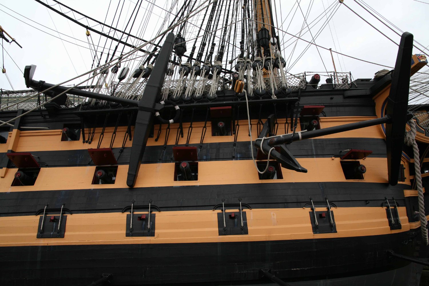
 Bill, I notice your emergency steering chains ran too far up the hull. Here is a shot I just noticed recently added to a build log for HMS Vanguard by Bikermart.
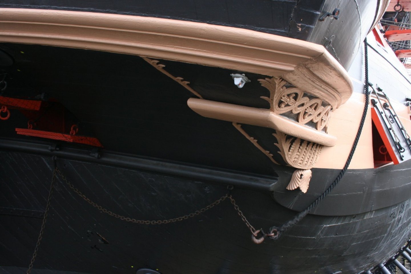
-
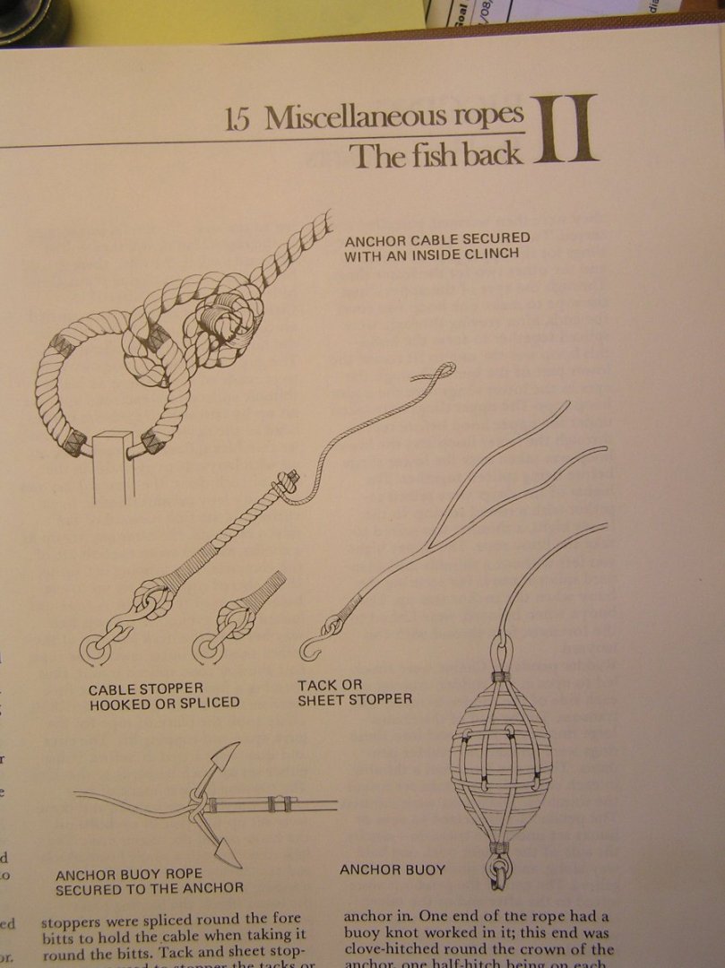
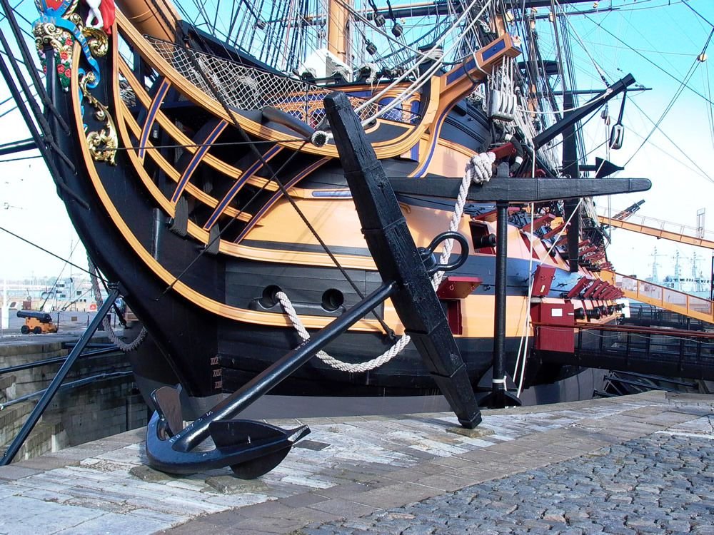
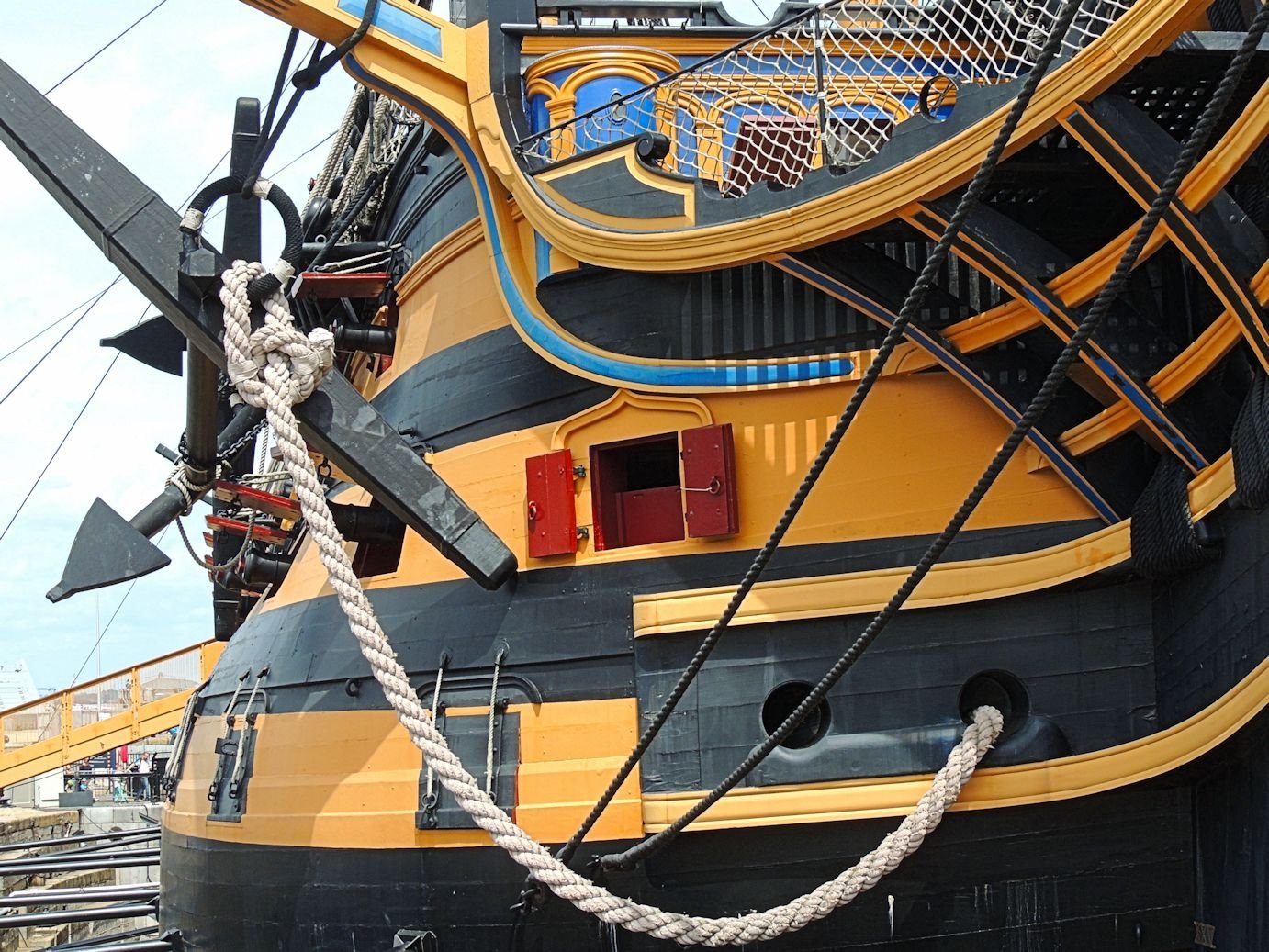
That lashing on the bower anchor is the line connecting the anchor buoy; the anchor buoys are those black objects tied up in the shrouds; they're basically a barrel-like object wrapped in canvas and tarred. The buoy's line is coiled up and tied to the shrouds. The second buoy, for the sheet anchor, has no line on it and is simply lashed to the shrouds. The stream anchor lashed to the sheet anchor is 3rd party; Heller only provides the four bower and sheet anchors. There is another smaller anchor, the kedge, lashed at the starboard mizzen channel, also 3rd party. I omitted the small kedge anchor. Here are some nice relevant drawings from Lees: Top left shows the servings on the anchor ring, or "puddening". Lees has the colours reversed - the entire thing is black, with four white lashings. Speaking of anchor rings, I recommend you cut them off your anchors and replace with a brass ring in a drilled hole. They do not hang realistically with the plastic ring rigidly in line with the shank. As I said I can't recall who it was I helped with anchors before, but I did find a couple of pictures I used at the time. Here they are for your viewing pleasure. Doesn't she look great? Since I found the pictures I will give details below. This shows the port bower hanging by the cat falls, in the first catting operation. This operation is hooking the anchor ring with the very large hook stropped to the triple cat block, after the anchor breaks surface when lifted by many men on the capstan. The running end is led through the large snatch block on the bulwark just aft of the cathead, then I am not sure what happens - led to a capstan? hauled on by many men (only one sixth the effort now)? At any rate the cat falls can only get the ring so high because of the bulk of the cat block and hook. This one shows the starboard bower after the second catting operation. The black "cat stopper" clinched around the cathead is passed through the ring, back up through the very large cleat on the back side of the cathead, and belayed on the large timber head at the corner of beakhead bulkhead and bulwark. After this, the cat block and falls are unrigged. The ring puddening is clearly seen. This pic shows the shank painter on the bower which is the fishing operation. An eye on the bottom of the channel holds a chain which is passed around the shank. The chain is connected to a rope which is belayed on, I guess, a timberhead. Can't recall and I can't see this black-on-black on my cased model. They used a "fish davit" temporarily mounted above the channel as a crane to hoist the business end of the anchor higher before tightening the painter. Heller did not provide fish davits. Copying Blue Ensign, I made some and stowed them on the foredeck. Also seen is the chain securing the sheet anchor to the pad on the deck. It attaches to an eye on the side of the hull, and another on deck. What isn't clear here, maybe it is black too or maybe they omitted it since these are fiberglass replica anchors, are the lashings I showed in natural on my sheet anchor. The one on the upper arm of the stock ties to an eye under the channel, as I remember (again I can't see it on my cased model). The one on the lower arm belays on a timberhead. These crossed lashings lock the anchor in place.

-
Yes, although it is terrible what we are seeing in the news from Florida, it's amusing to keep hearing how powerful "Ian " is, especially after hearing the same thing last week about "Fiona". My daughter's name is Fiona; it's odd that both our names came up as hurricanes in consecutive weeks.
-
You give me too much credit Bill. Many times when you asked a question I simply opened up Longridge to find an answer; sometimes I forget some of the technical names for things. Anchors are more involved than you might expect. Longridge doesn't give his usual thorough coverage nor does Petersson mention it. I benefited from Blue Ensign's treatise on the topic, on the old Pete Coleman site; cat falls, cat stopper, shank painter, etc. Somewhere on this site I described it all for another Victory builder but I forget who.
-
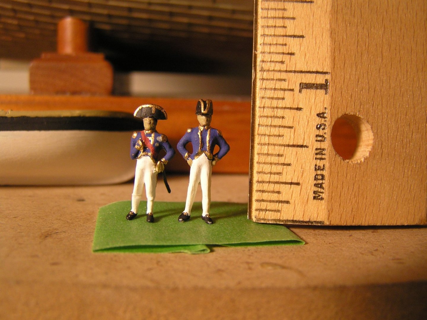
Hi Chris, Yesterday I saw on a Victory build log that you now produce a figure of Lord Nelson in various scales. The depiction is great! I would like to suggest that you produce an accompanying figure of Captain Hardy. I am certain that many Victory modellers would like to add these two men to their model. I copied Blue Ensign's conversion of spare Revell 1/100 men to Nelson and Hardy for my Heller Victory but if you had both available I would replace mine with yours tomorrow. One question: how tall is Nelson at 1/96, is he accurate to his actual (short) height? A Captain Hardy would need to be taller. Thanks. Ian
-
Very nice model! Regarding the lower ratlines, they didn't all span across all the shrouds. Consult reference books for details.
-
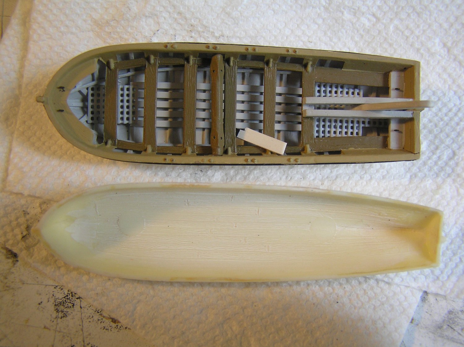
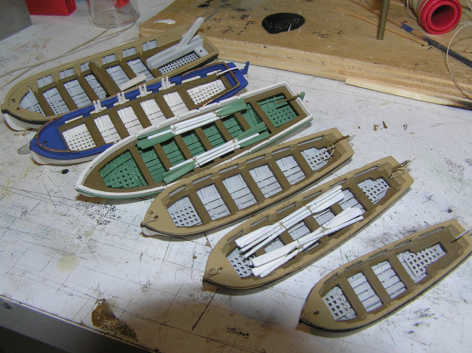
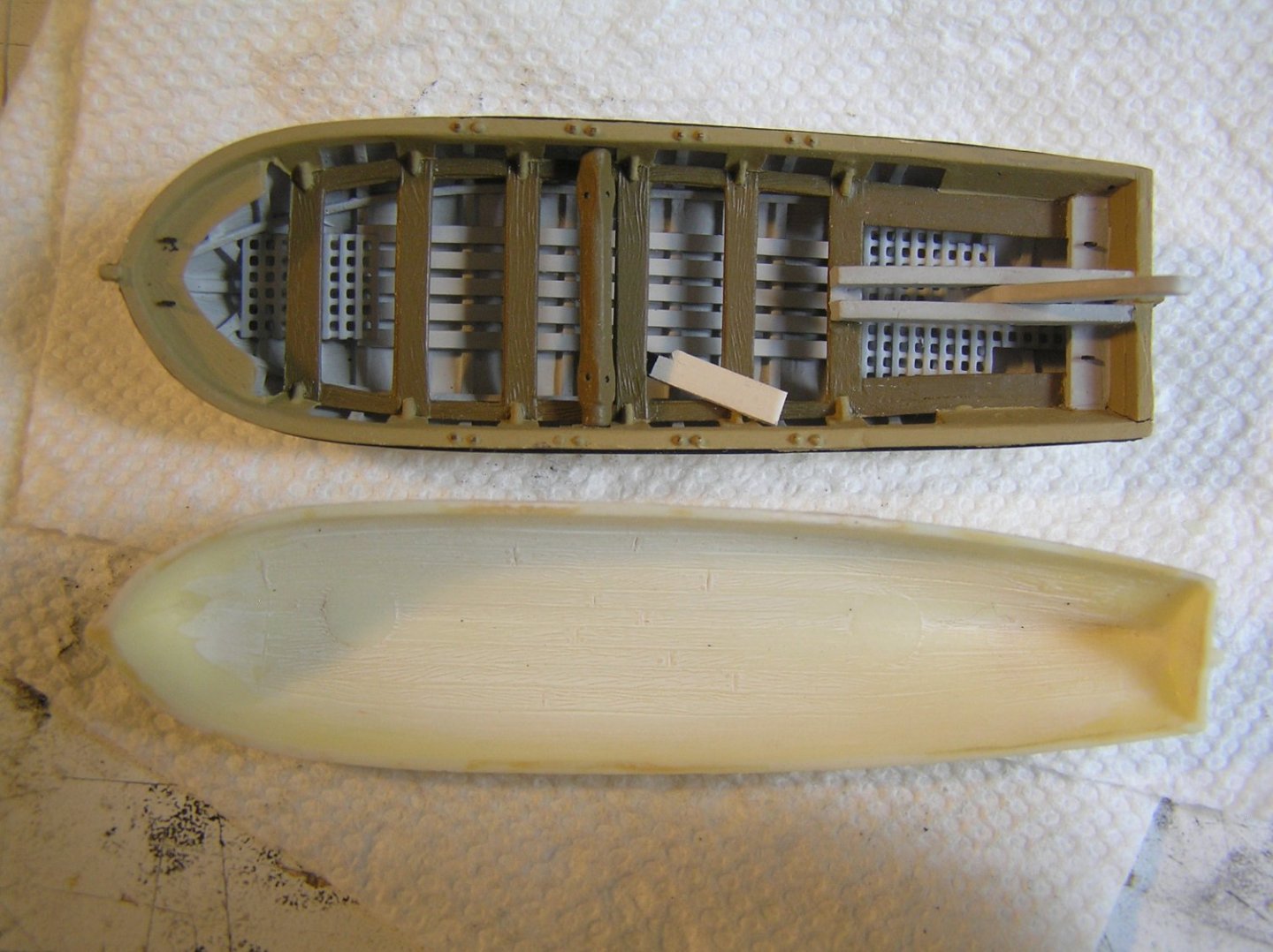
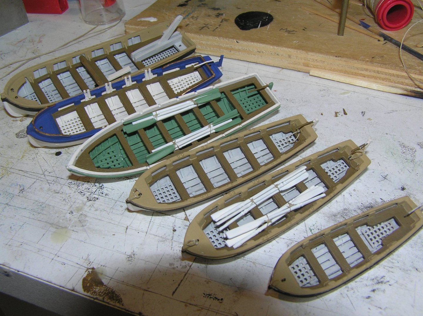
The provided boats themselves are lacking, both in numbers and details. Victory carried six. I seem to recall that you added some ribs or floorboards to yours, but do you have any extra Revell boats in your parts box from earlier builds? They could be pressed into service. Blue Ensign went to much trouble over his boats, especially the pinnace, which inspired me to do the same.
-
Wow!! Just took a look at Chris's figures, which didn't exist when I finished my build. I may buy 1:96 Nelson and Hornblower to replace mine.
-
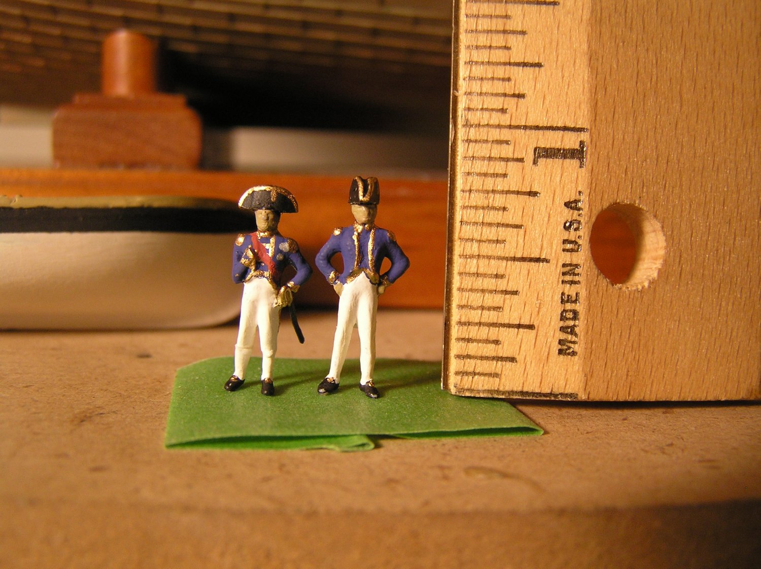
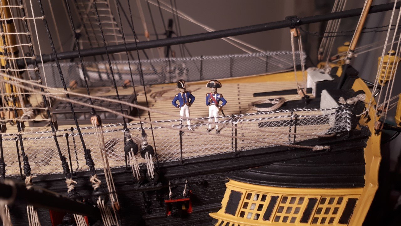
Bill, you can get an ensign and a union jack, period correct, from BECC. They make several sizes. I never did add a commission pennant; couldn't find a period accurate the right size. Maybe someday I can add one. The rudder chains become rope; they pass through a hole in the channel just in front of the gunport with the double lids and end in a knot. Blue Ensign converted a Revell figure to Nelson, and another to Captain Hardy. I copied him. We used the figure standing with arms akimbo. Cut off Nelson's arm and use a sliver of evergreen to fashion the pinned-up sleeve. Cut his legs at the knee and remove a bit then reattach since he was shorter than Hardy. Shave down the lower pant legs to simulate stockings. Add uniform coat tails with evergreen. Fashion the bicorn hat from evergreen with a drilled hole to glue onto his head. Add a sword from brass tube. I even added a queue to Nelson but it cannot be seen behind him. Remember, Nelson wore his hat in the older style, across his head, while Hardy wore his in the new style, fore and aft. Here are my Nelson and Hardy. My "flesh" paint was a bit thick and went on as a bit of a blob unfortunately. They look awful close up, but at viewing range they look good. Hardy's "stockings" didn't go well, or maybe I just gave up after Nelson.

-
Congratulations Bill! Very well done! No mean feat rigging a Heller Victory. And in record time too! Just one hurdle remaining in this steeplechase - the painting of the lanterns....😀
-
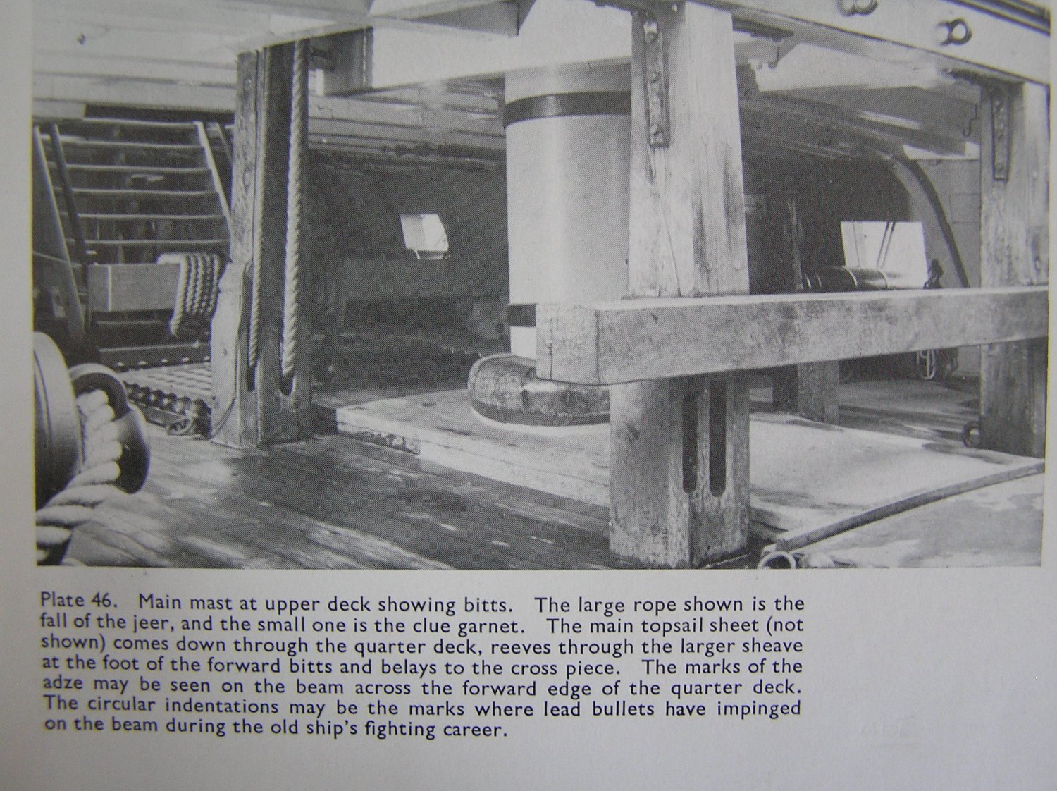
The painted breeching rings look great! Don't worry, nobody will be able to tell on the finished model. There should be two glossy pages with photographs from the real ship between the pages you show in your photo. Evidently someone has torn them out. It's not unusual for old Longridge books to be missing some of the pen and ink drawings, but some photos??? 🤨 You could check your book for missing pages by looking for the Plans and Plates listed on pp x-xi. Here is the missing page at issue here; the text is helpful.

-
Bill I meant the 3rd photo of post 1376, but this one will do. Your white driver sheet which runs between the upper block on the driver boom and the block on the traveller bar should not be wrapped around itself, it should belay on the cleat just forward of the bar.
-
In the 3rd photo of your post, the running end of the sheet is wrapped around itself between the blocks; this is frapping, just like on the bowsprit gammoning. Just unwrap it and belay on the cleat instead, then throw on a coil. A quick fix. 🙂
-
Bill, nice job on the coils; that's a tedious task. I wanted to have slack lower braces with a nice sag but I just could not get the thread to adopt the same (plus you then need to get the clewline to look taught, somehow). Tried smearing some glue on and rubbing it etc but no luck, so mine are taught. I noticed in one of your photos that the driver sheet is frapped around itself between the blocks; the running end should be belayed on the nearby cleat see pg 268.
-
Bill, that's the snatch block fitting that should be on the bulwark in accordance with Part 12. I believe I had to glue it on straddling the aftermost hammock crane then drape the netting over it. The brace can then go through it and then to an ordinary deck cleat as in Longridge pg 268. The cleats to use are the aftermost ones shown in Part 10 "Fitting the Poop Deck etc.". It's a small miracle that Heller got the number of cleats and eyebolts (to tie blocks to) correct on each side, exactly in accordance with Longridge.
-
Bill, the snatch blocks are part #67. Heller instructions show where they are placed in Part 12 "Fitting the Hammocks" (on my older instructions). You have to look very carefully to notice Part 67 at the end of bulwark under the hammock netting.
-
Bill, she's looking very nice indeed but there is one more detail you could add, specifically the lizards supporting the main braces. See Longridge pg 251 and diagram pg 252.
-
Nice work. Those are hefty-looking davits; these whalers seem to have been built like tanks for their three years away voyages.
-
Love the locomotives. Are they the metal kits from from Occre? I was looking at some of them last time in the hobby shop and thinking they looked awesome, but they don't come cheap......
-
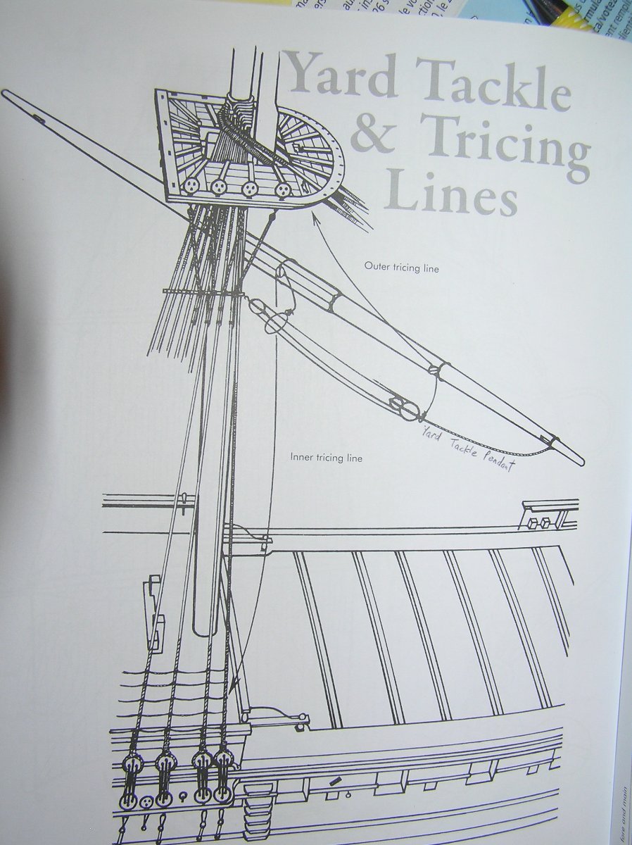
Yes I did. They are very confusing to read about in words and I don't recall Longridge having a diagram. Here is Petersson's diagram instead. It's just a tackle hanging off the ends of the fore and main yards for use as cranes to lift heavy stuff. When not in use, the hooks are hooked onto the forward shroud and the tricing lines "trice it up" close in to the yard out of the way. Petersson doesn't show the tricing line belays. According to Hackney the tricing lines each pass through a small block attached to forward shrouds just beneath the futtock stave then lead down and are belayed at the bottom of the 2nd shroud. The yardarm tackle is belayed at the bottom of the first shroud. Not sure how he meant, exactly; I just tied them under the lower deadeyes. I see Longridge shows the tricing lines at the first deadeye. At the end of the day you could just omit them. I doubt they were rigged permanently.

-
Kevin, are you aware of photogrammetry? Might be a quick way of getting Revell's hull lines into CAD.
-
Just a note to reinforce in your mind that the cro'jack yard braces "cross" i.e. the port brace belays on the starboard side, and vice versa. (Longridge pg 258). No other braces cross in this fashion.
-
I brought mine out to about as far as the gunport lid reaches, which is more or less the channel too. I should have mentioned that there was some debate on the Pete Coleman site about whether/when this bracket existed. It's not on the ship today; the block just attaches to a ringbolt in the side. I just decided to followed Longridge.