HOLIDAY DONATION DRIVE - SUPPORT MSW - DO YOUR PART TO KEEP THIS GREAT FORUM GOING!
×


Ian_Grant
-
Posts
2,108 -
Joined
-
Last visited
Content Type
Profiles
Forums
Gallery
Events
Everything posted by Ian_Grant
-
 Good recovery, Bill. 👍
 -
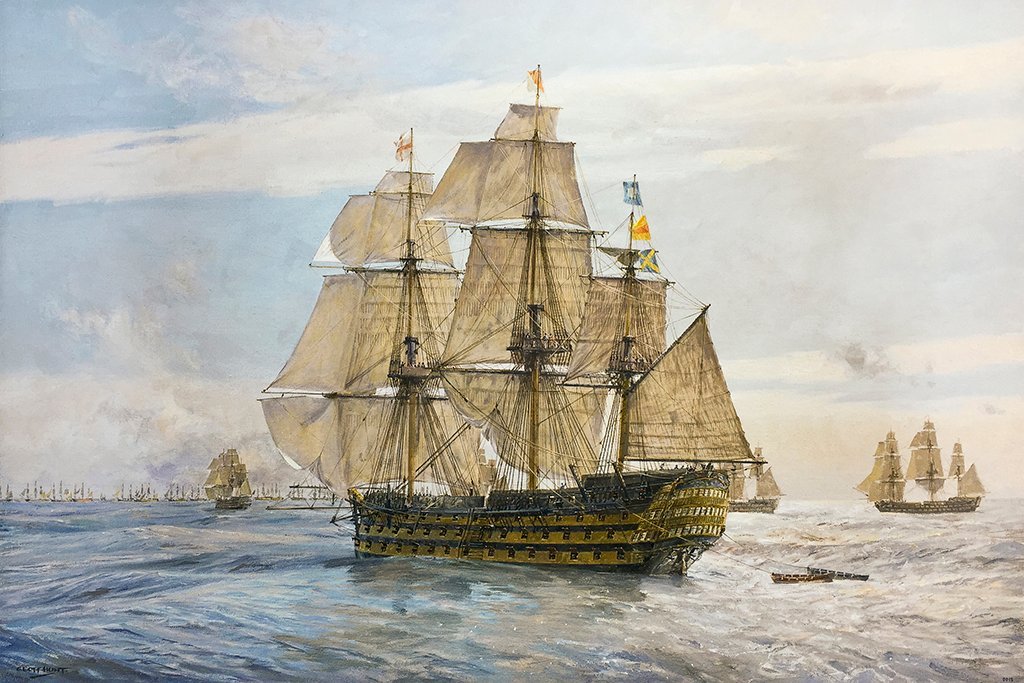
Bill, just to clarify, the topgallant yards would not have had booms or boom irons like the lower yards. The topgallant stuns'l's foot would be set on the topsail yard boom, and its head on a small spar dangling from a block on the topgallant yard. You can make this out on the Geoff Hunt print.
-
Looking great! I happened to catch your talk of thin line - I'm searching for something to use for ratlines at 1:150 scale, something fine and non-fuzzy. Would this cotton line meet the need; if so what is it please? Thanks, Ian
- 740 replies
-
- 1
-

-
- Tudor
- restoration
- (and 4 more)
-
No I just ignored them as this light equipment would be stored until needed. I did however make fore and main royal yards for her, which I stowed lashed to the inside of the topmast shrouds, one to port and one to starboard.
-
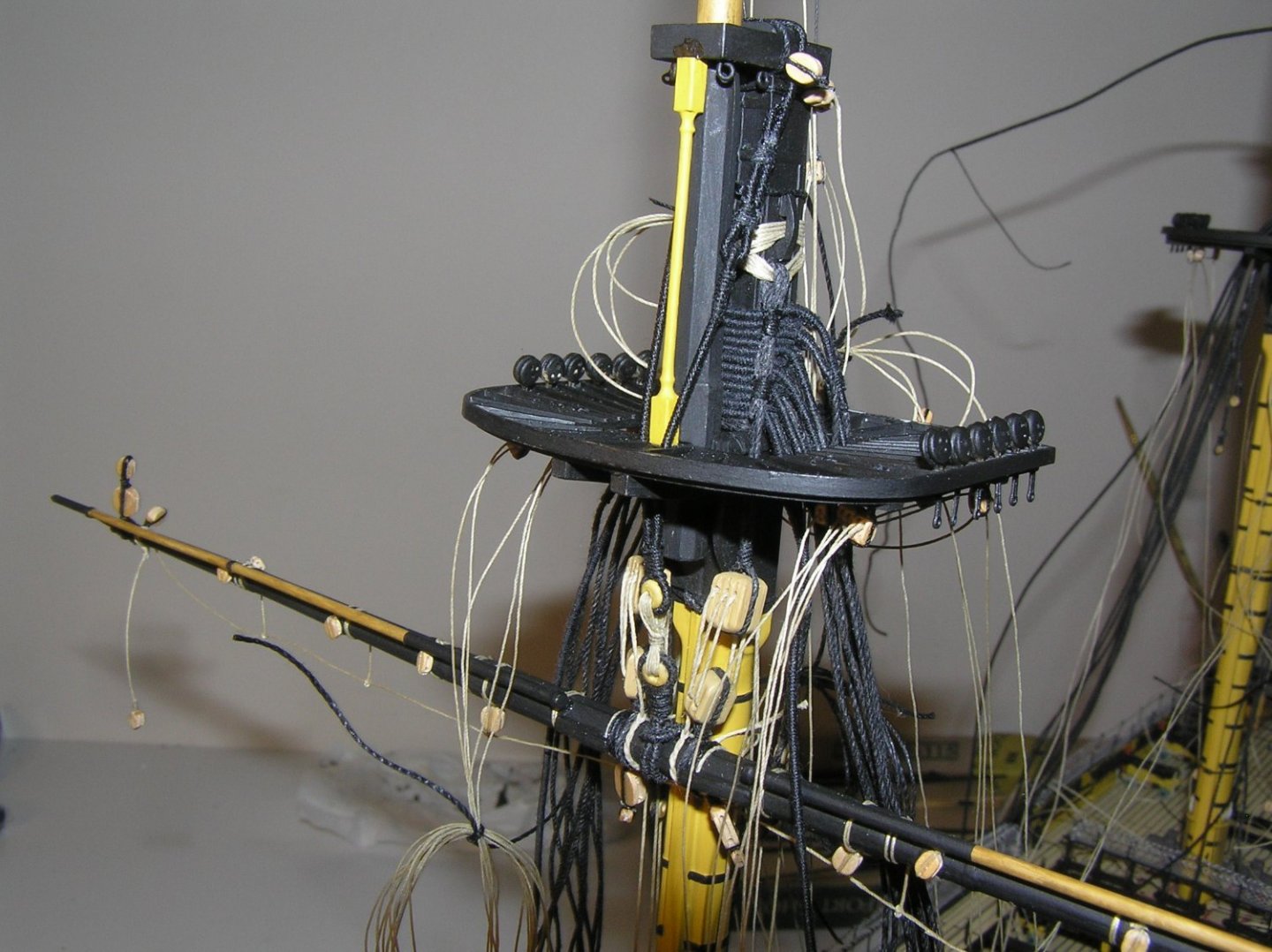
Very nice! I find your topmast cross-trees more convincing than Heller's strange interpretation which has the masts between the 1st and 2nd cross-trees and the 3rd dangling out way in back of the masts.
- 69 replies
-
- 1
-
-
- soleil royal
- deagostini
- (and 1 more)
-
Bill, according to my print of Geoff Hunt's "England Expects" which depicts Victory plodding into Trafalgar in very light winds, she had stuns'ls on the fore and main topgallant yards too.
-
Just wondering how accurate that is - I'm not a CS expert - but there would be a lot of force on that railing stanchion from the chain holding the fluke end! Or are those stanchions iron too?
- 481 replies
-
- 2
-
-
- Cutty Sark
- Revell
- (and 2 more)
-
I think the main reason windjammer ratlines didn't need to be as wide is because there were far fewer men trying to get aloft at once; Victory for example would put more men on a topsail yard for reefing her massive sails than Preussen probably had on watch. Earlier in this log there was a brief discussion on ratlines and shrouds. Veszett in post #43 sent pics of a model showing six shrouds on the lower masts with ratlines spanning four, or six for every 5th one; also a photo of Preussen a few posts later that seem to show six. Heller only has five shrouds which I ended up not changing. So I suppose I could do three, or five every 5th one. That would be somewhat fewer knots than I estimated. I don't mind the tedium of tying the knots, I'm just afraid that at 1/10" spacing they'll look more like a solid wall unless I can find some very fine non-fuzzy line. I may cheat and go to 1/8" spacing; just don't tell anyone! 😄
-
SIB (Skier in Bottle) by Glen McGuire - 1/80
Ian_Grant replied to Glen McGuire's topic in Completed non-ship models
Makes hot chocolate the best ever! 👍 -
Actually, I looked again at my Heller Victory, and it's not impossibly more knots than for her. Keep in mind that Victory's fore and main lower ratlines tie off to 9 and sometimes 11 shrouds so they add up very quickly too.
-
Thanks Kevin and Jerome! Jerome you have me thinking - the topgallant and topmast shrouds are only in twos and threes anyway so maybe skip the knots on the centre topmast shroud. For the lower, maybe just knot the two ends as well.....hmmm.....
-
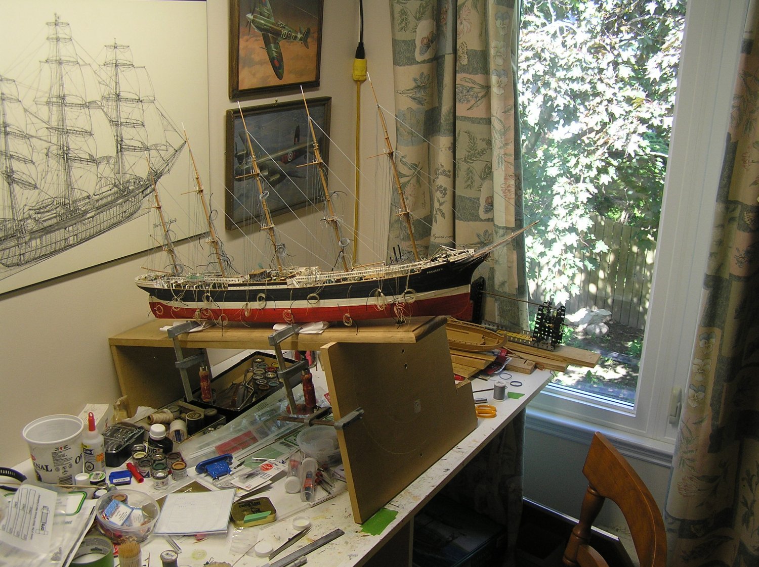
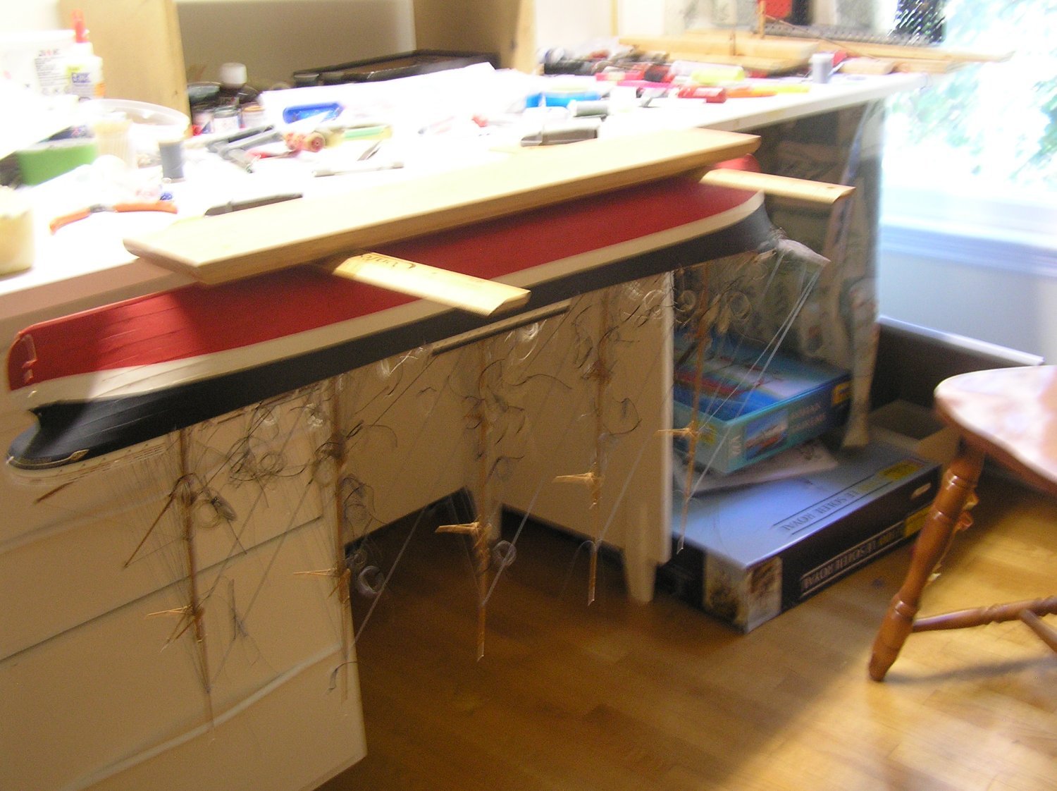
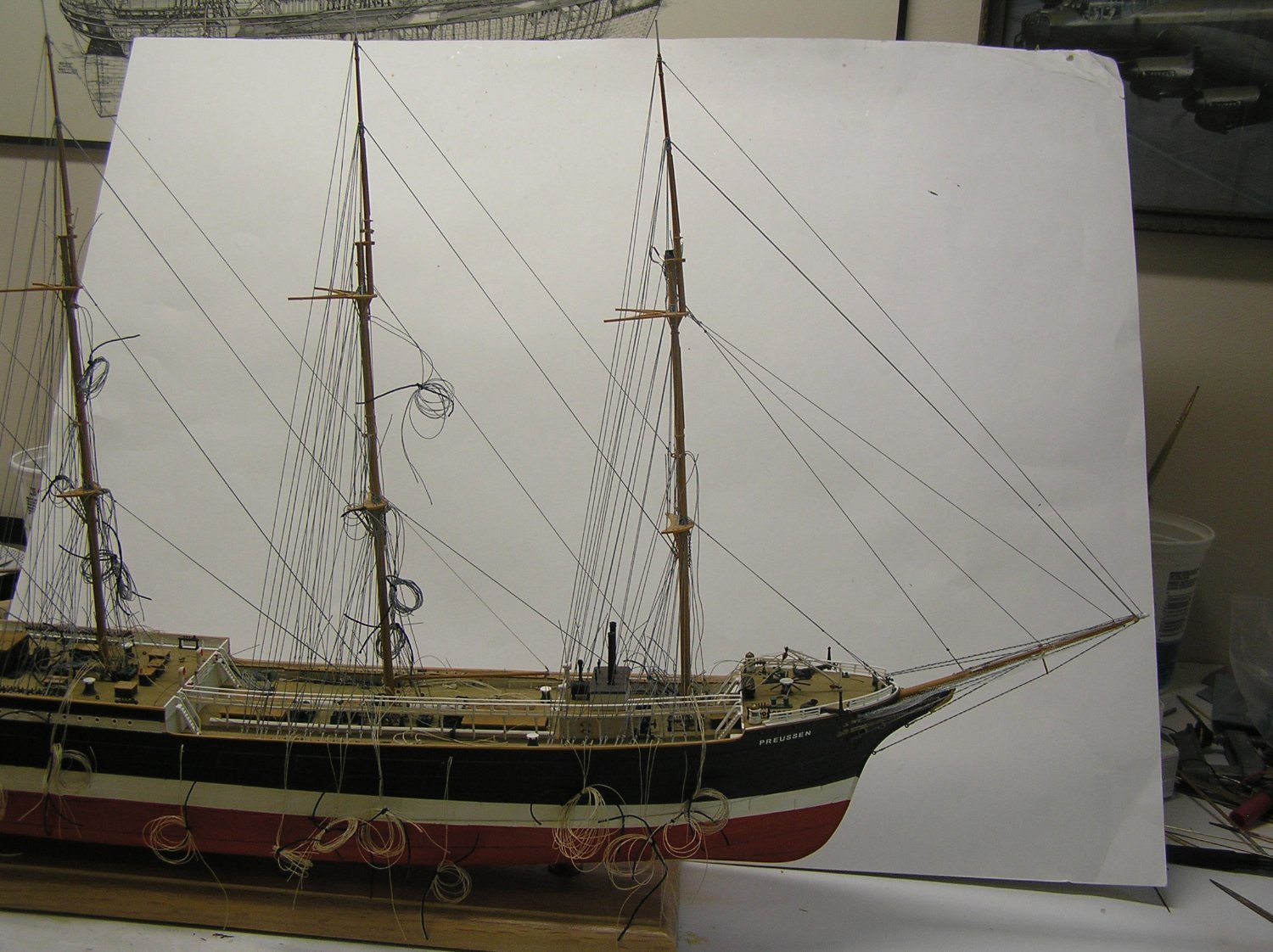
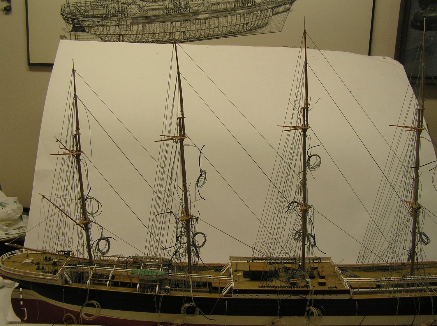
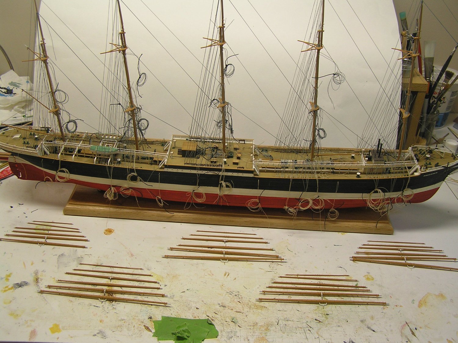
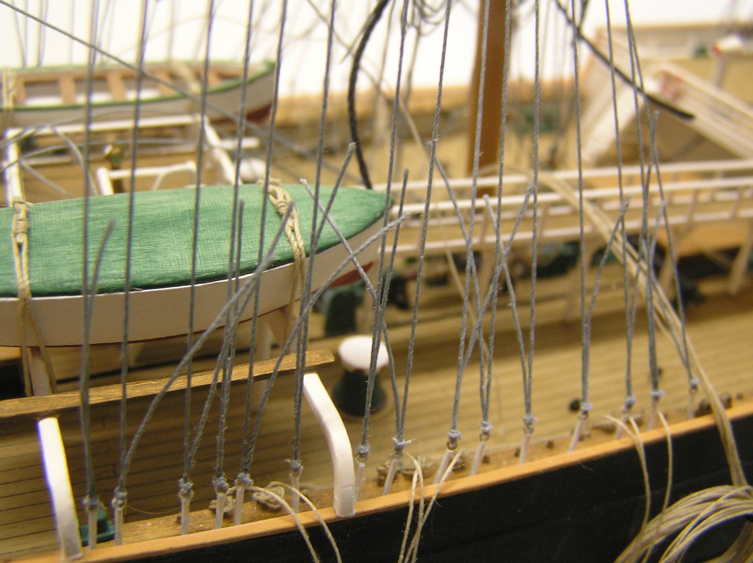
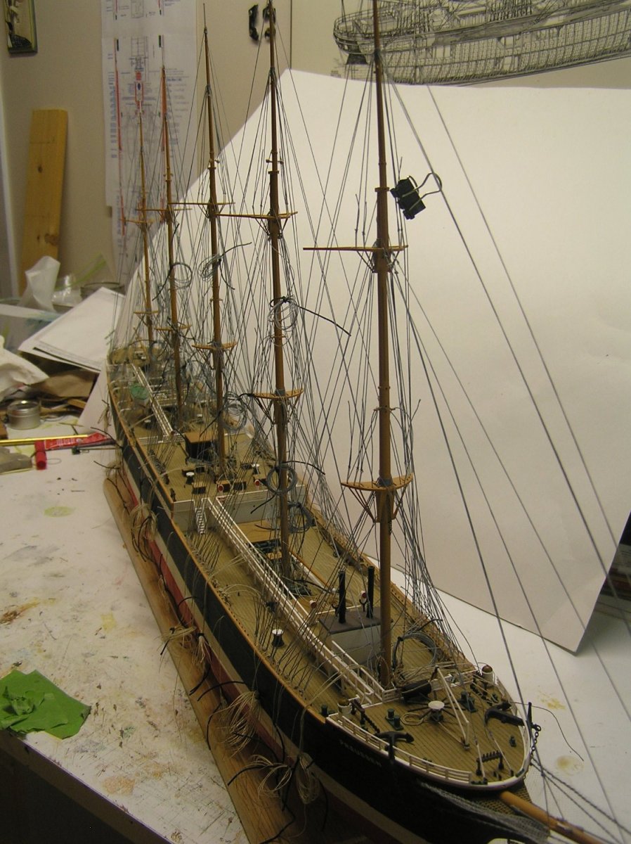
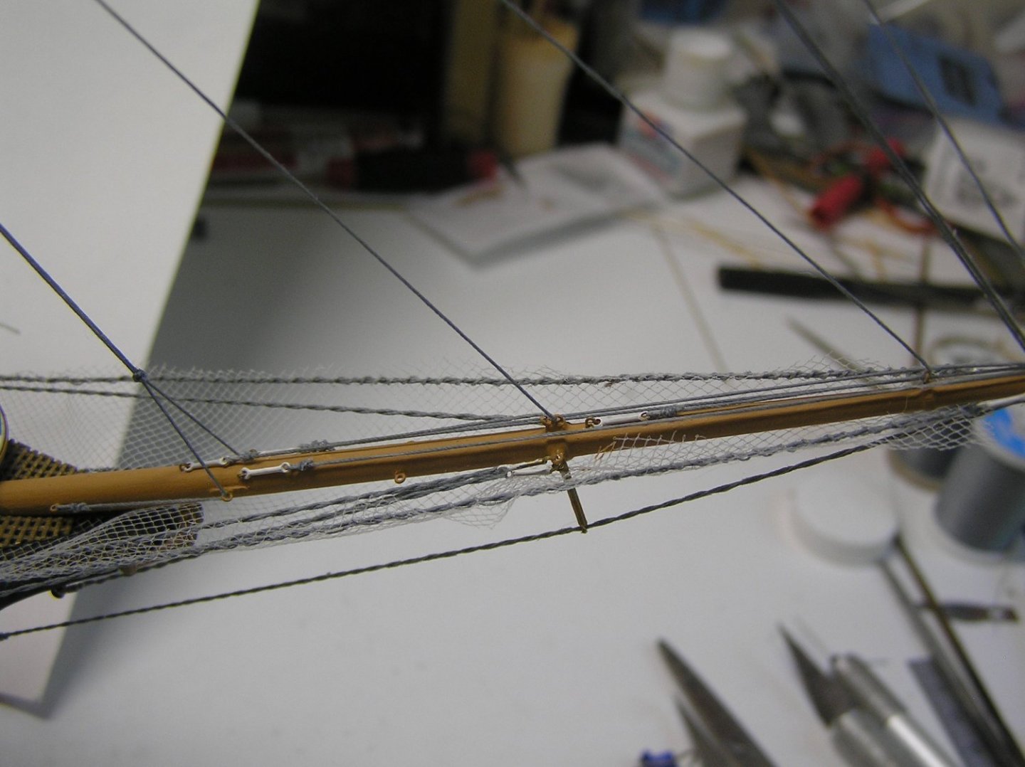
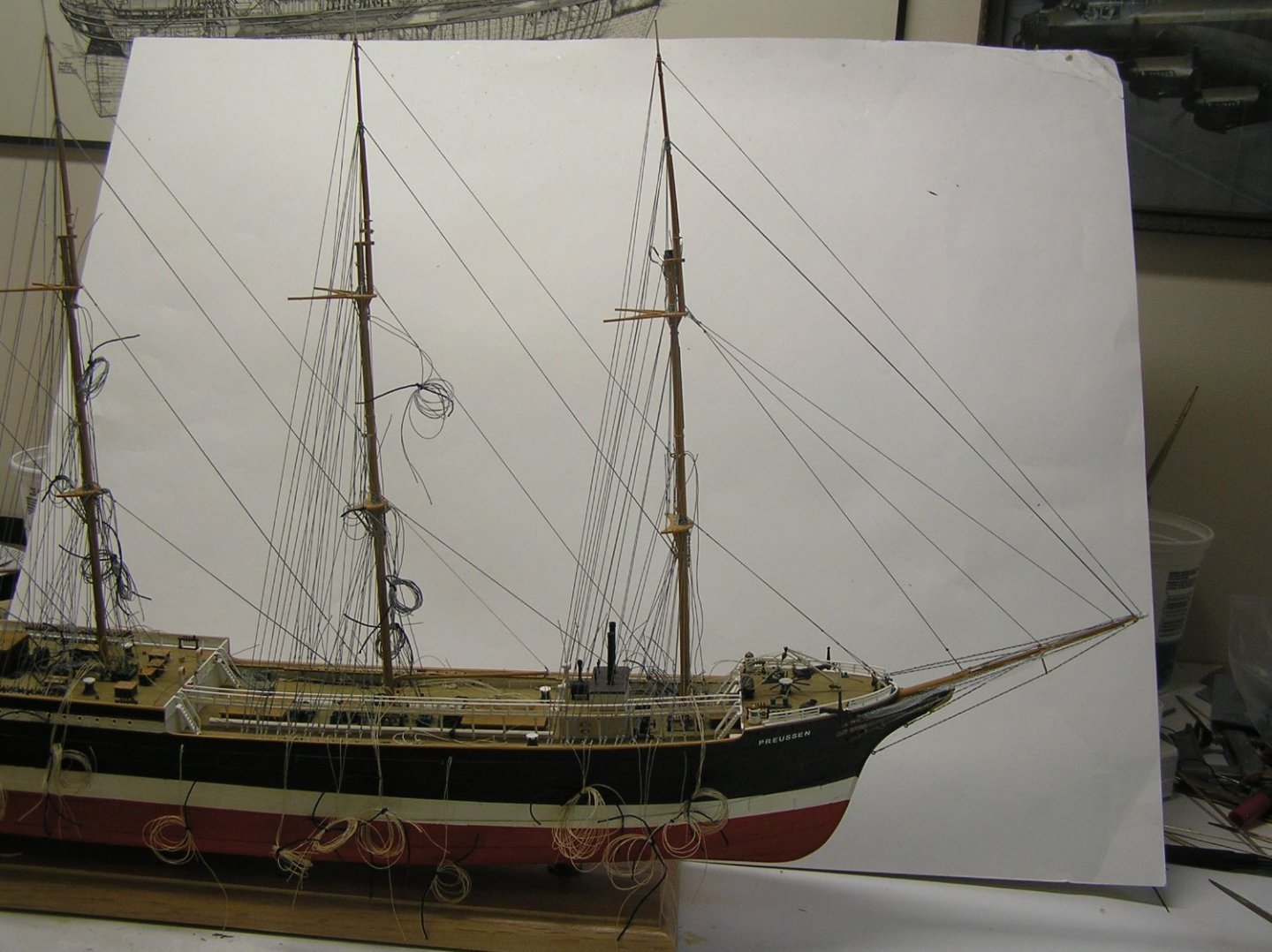
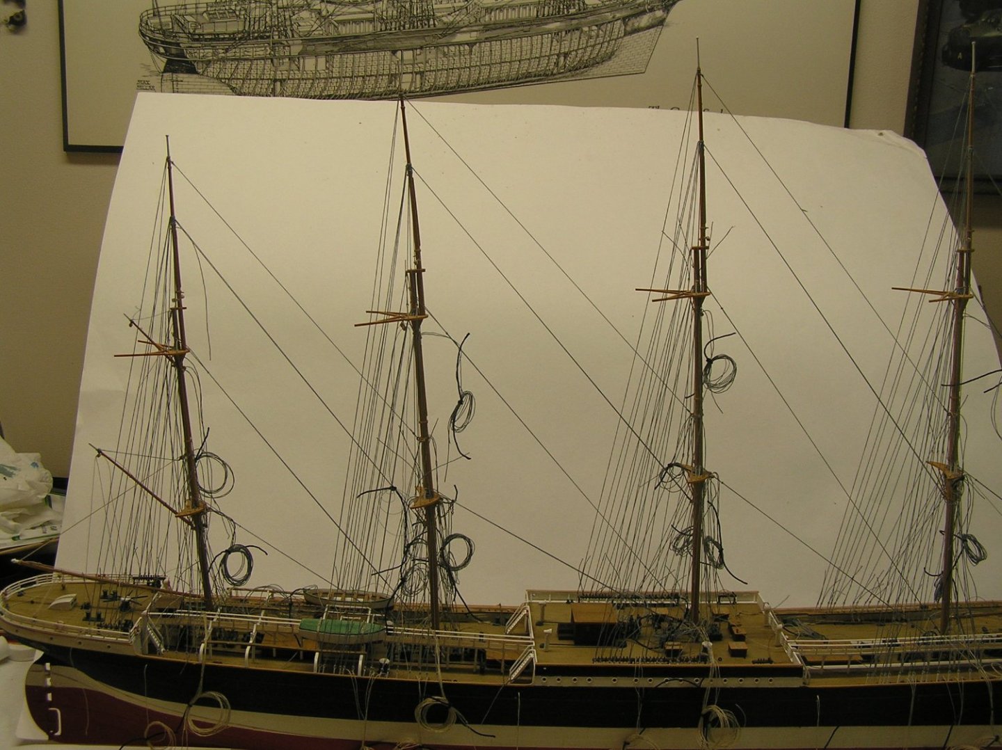
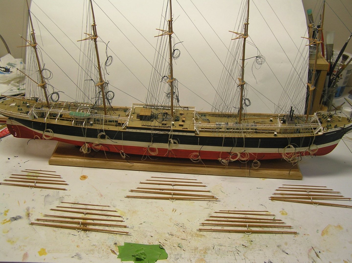
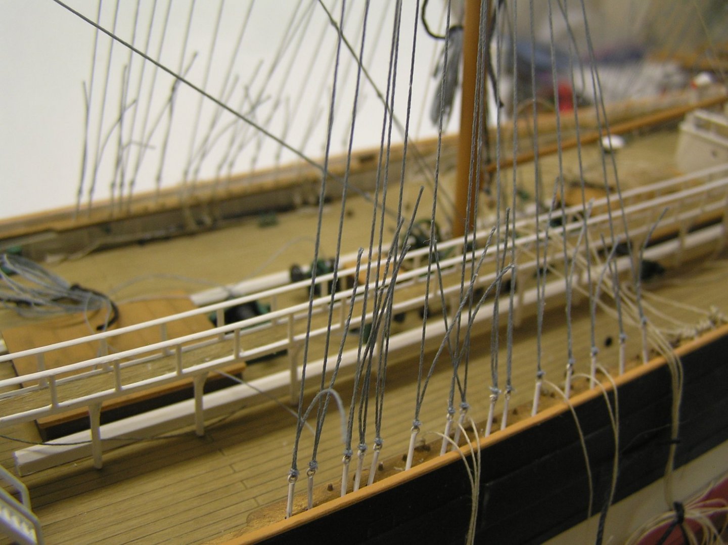
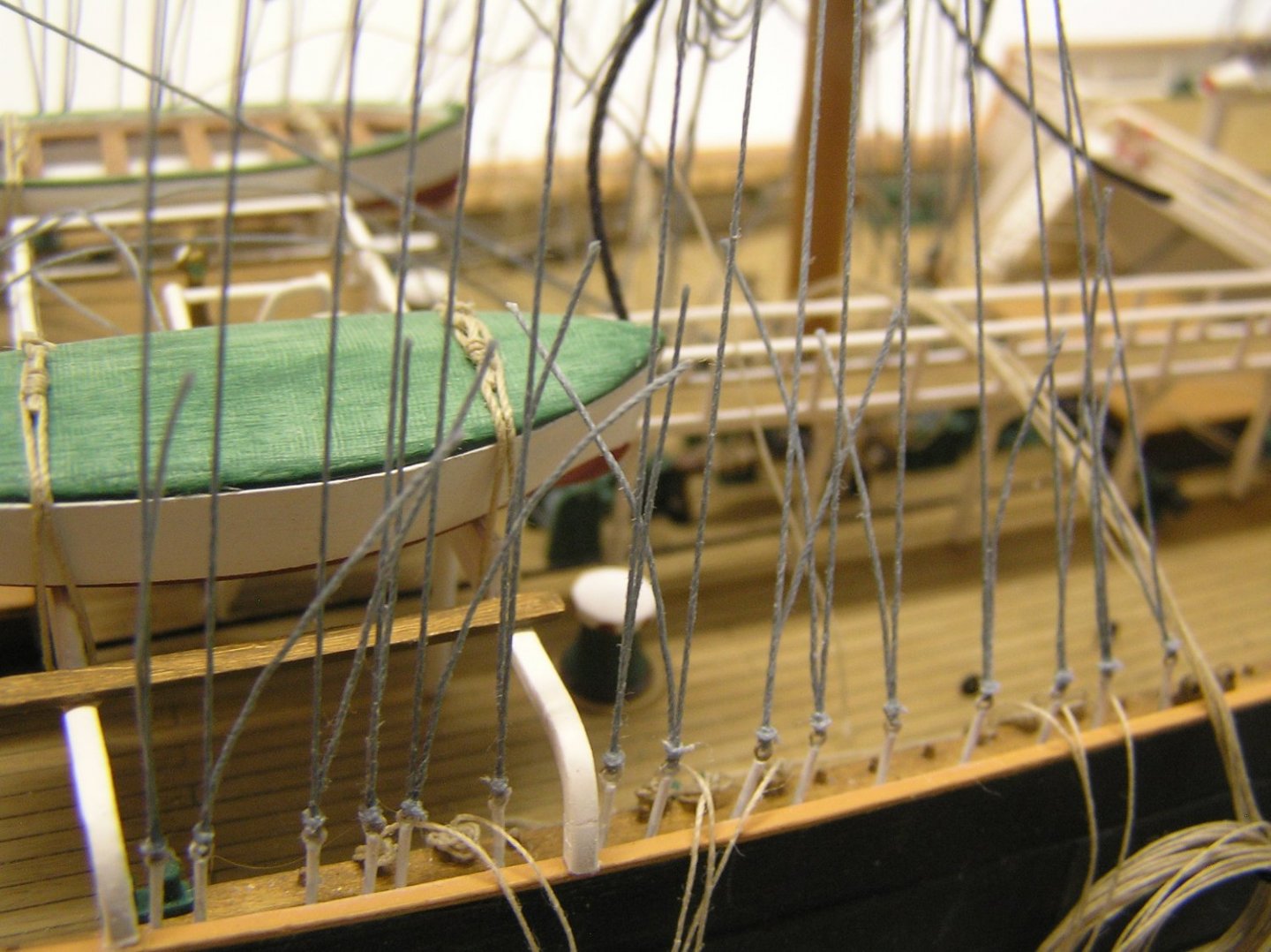
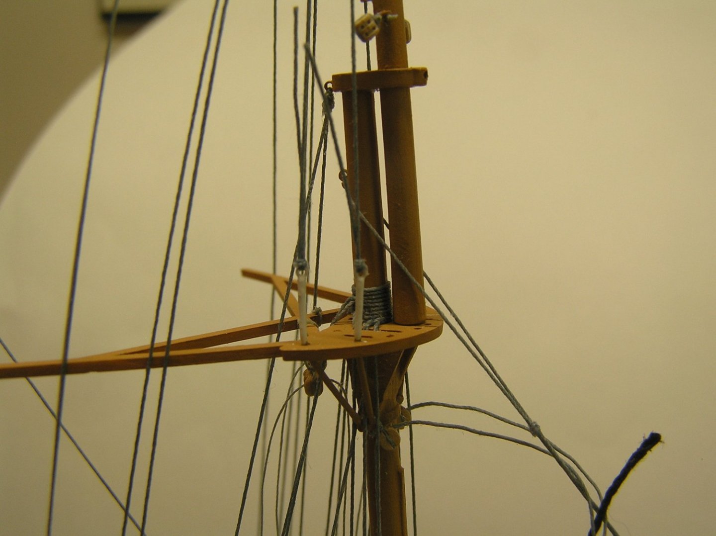
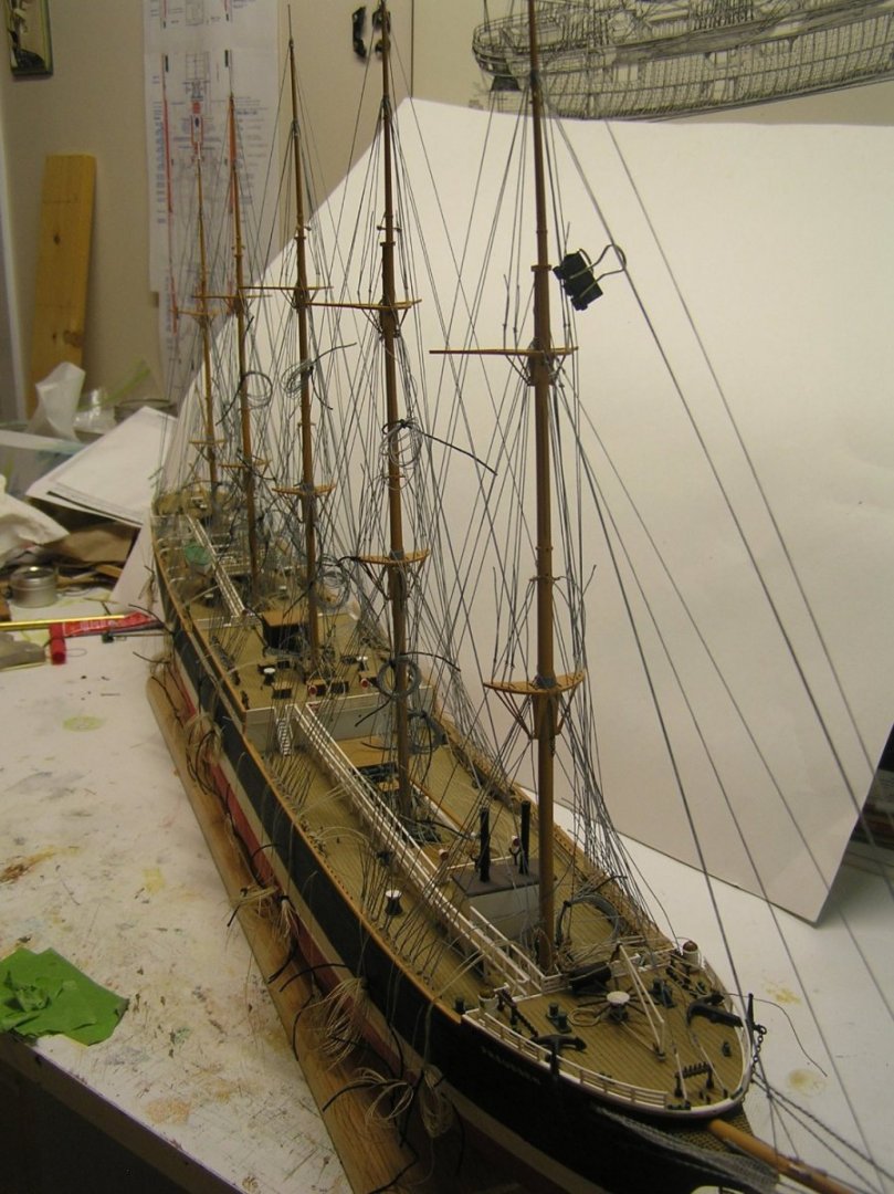
Standing rigging done at last! Well, except the ratlines. I accidentally bumped the bowsprit and broke the martingales. Glued them up but the outer broke again later, I barely touched it. Needed to get beneath to work on it. Tried this arrangement, but lighting from below and dazzle from above were issues..... ....so switched to this setup which was much better. I ended up replacing my brass tube martingales with thread, doubled and twisted like I did for the guys. I also replaced the dolphin striker with a slightly stouter tube. Last standing rigging line to do was the fore royal stay. Wouldn't you know it, when I pulled it taut my little white rigging screw on the bowsprit came apart - brass tube separated from the etched eye on the bowsprit; not enough glue. Then the damn thing twinged off my tweezers while I attempted to re-glue it and went off to the 4th dimension. Had to make and paint a new one. Here's a shot of the bowsprit with its rigging screws. The two on the centre line tighten the inner and outer jibstays; the one to port (barely seen) is the doubled fore topgallant stay; that to starboard is the fore royal stay (single). This is all in accordance with Longridge. I doubled the topgallant stays too, just to give them some "heft" as my thread is slightly smaller than scale. Still haven't trimmed the safety netting! Also realized I forgot the footropes but at this point I will leave it as is. Here are some shots of the current state, with my patented background white. Not bad except the fore and mizzen topgallant masts ended up bowed back a little. Especially the fore mast. But athwartships alignment is good! For the running rigging I drilled holes through the pin rails adjacent to the vestigial pins Heller provided. Lines pass through the hole and are tied in a knot, then covered with little "coils". This photo was meant to show this but the coils on the opposite bulwark rails are, sadly, out of focus. The untrimmed ends of the shrouds await their white seizings, between the ratlines. Shrouds, stays, etc were simply clove-hitched to the masts. It looks ok as seen here although the accumulated turns are double that of authentic rigging. No one will know except us. And finally a shot which attempts to show the density of the backstays on this ship. I just noticed there is a clip still on one of the fore topgallant shrouds....oops! Last major task is to add the yards. Each requires four blocks of some sort, for either clew lines or downhauls depending on whether it's a fixed or movable yard. The topsail sheets will be chain, slightly over-scale but I wanted to show them as such to add to the majesty. 😉 As you can see there are many yards. Still undecided about their footropes......at this scale......leaning towards no. But just before I get there.......ratlines!!?? To be in scale I'd need a ratline every 0.1" times five masts. I estimate 3100 clove hitches. 🤪😭 Not sure I want to do them but feel ship would look odd without them........ I have no idea what to use for these..........fly tying line?....wire?....any suggestions welcome.

-
I used a pen along my Victory's deck seams but I will never do it that way again; for Preussen I just applied a wash which was left in the seams after wiping. Much easier and probably more permanent.
-
WARNING: Rant on US/Canada border trans-shipping ahead.......... Well I got my package from Servocity today. If I thought my heart nearly stopped when I saw my Cart total, it came even closer when the UPS guy wanted another $109CDN from me at the door for, ahem, GST and brokerage fees and taxes on brokerage fees. This on top of already paying $49.44USD for shipping $188.57USD worth of parts to the border. Servocity has a standard shipping fee of $8.99USD within the USA, so a US resident of Ogdensburg, say, gets his/her shipment for $8.99 but I pay $40USD more for my shipment to travel the extra 6km to the border. Then add $69.30 for brokerage fees and $9.01 tax on that. Finally add Canadian GST which is also applied to the shipping fees not just the product value. Bottom line, I received $188.57USD ($236.83CDN) worth of parts for $408.28CDN to my door, an increase of merely 72.3% in shipping and up charges. RIDICULOUS! HIGHWAY ROBBERY! And that just allows me to PARTIALLY build ONE SIDE of the galley mechanism.....at these prices I may use these parts as drill guides and revert to a mix of metal and wood components, or maybe just give up altogether.
- 536 replies
-
- 1
-

-
- Quadrireme
- radio
- (and 1 more)
-
SIB (Skier in Bottle) by Glen McGuire - 1/80
Ian_Grant replied to Glen McGuire's topic in Completed non-ship models
Nice idea! But where is the penguin? 🤫 I too have a passion for Disaronno Amaretto, in hot chocolate, when camping. -
Ah! I thought they might be that, but I don't see any sign of a lens/window/viewing slit? I'll have to look up how they worked.....
-
...."Probably only until my wife comes downstairs." HaHaHa 😄 Very nice model build! Pardon an uneducated question, but why does the first turret lack the protuberances on the aft sides that the other three sport?
-
The 10" leech and buntline blocks on the lower fore and main yards scale to 3/32" on the model, about 2.5mm; not far from the length you used. But have a look at the blocks from "Syren" on my model (below). They're far less bulky for their length. In fact they look exactly like the buntline blocks pictured in Longridge PLAN NO 8. Also note that they're lashed on the front of the yard. My topsail sheet and lift blocks are also less imposing but realistic. I agree with Marc; if you have a collection of these blocks then go down one size perhaps. I don't recall what Kevin made for you.
-
Kit Review Seebäderschiff FUNNY GIRL 1973 - HMV - 1/250 - CARD
Ian_Grant replied to ccoyle's topic in REVIEWS: Model kits
What a pretty boat! Very nice. By the way Chris, your new user photo is much more dignified and serious, but I still like your previous one. 😉 -
Rob, didn't realize you moonlighted as a hit-man. 😄
-
Fantastic! I should have asked you about printing me some Jarvis brace winches......if you ever do a Preussen/Potosi/Passat/Pamir you will be able to improve the kit's offering.😉
-
Just a note to myself so I don't lose the figures..... Plotted some more parts in Tinker; in order to have two 30mm linear bearings on a single shaft for separate upper and lower oar beams, the drawer slide bottoms need to be 21mm below water level to prevent the two bearings interfering on the shaft. This allows upper oars to move over a greater range than the lower, while still allowing lower oars to go up to horizontal if required. Shaft length is 95mm.
- 536 replies
-
- 1
-
-
- Quadrireme
- radio
- (and 1 more)
-
Kevin, nice pump! Will this really print in one piece in resin at this scale? I'm impressed! I drew better Jarvis winches for Preussen a while back, but my brother's 3D FDM printer couldn't make a nice job of them. Again, I really like your wood-look painting.
-
"...saved me from throwing the mother of all computer generated tantrums" HAHAHA! 😄 Thanks Kevin, I'll take a look at the video.
- 536 replies
-
- 1
-
-
- Quadrireme
- radio
- (and 1 more)
-
I have a wood mold for some unknown part of something I picked up somewhere or other years ago. It reminded me of a bygone era, and my dad.