Ian_Grant
-
Posts
2,156 -
Joined
-
Last visited
Content Type
Profiles
Forums
Gallery
Events
Everything posted by Ian_Grant
-
 Kevin she looks great. Love the new teak finish! And especially the negative deck planking, a vast improvement.
- 444 replies
-
- 1
-

-
- Cutty Sark
- Revell
- (and 2 more)
-
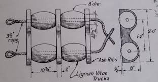
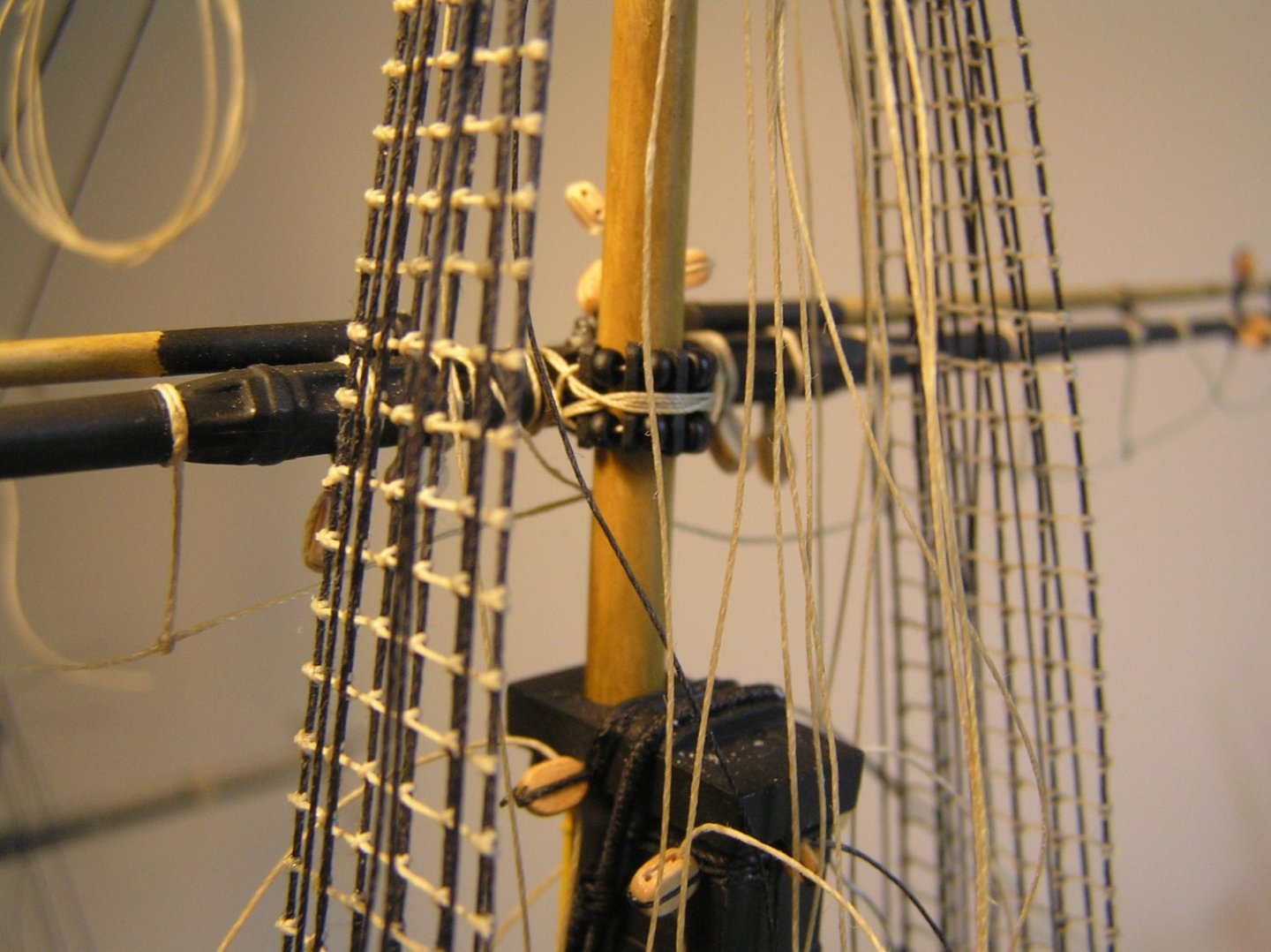
I just had a thought, Tom, that I need to add further info to clarify......... The above info only applies to lower yards like your main yard, which did not have to move up and down the mast as the sail was trimmed. Upper yards which slid up and down the mast were attached by parrals, sort of wooden beads on strings that wrapped around the mast, holding the yard against it while allowing it to roll up and down. Here is a detail: And here is an example on my HMS Victory model: Something of the sort will apply to your upper yards. Keep up the nice work!
- 146 replies
-
- 3
-
-
- Harriet Lane
- Model Shipways
- (and 1 more)
-
Tom, for planning purposes if you are rigging without sails.......... 1) For a given square sail, rig the sheets and clew lines and tie them to each other. They would have met at the lower corners (clews) of the square sail had it been there, so this is standard practice. Also what is shown in Longridge's large running rigging diagram. 2) Bunt lines can be passed through their blocks on the yard, then hitched to the yard or possibly tied in a knot too big to slip through the block. 3) Bowlines can be hitched to the yard, sort of at locations where they would have ended up had they been attached to a furled sail. It looks like you don't have the quarterdeck mounted yet. This is good - you need to attach threads for the main course jeers and clew garnets, and the main topsail sheets, to the bitts on the upper deck near the main mast while you have access before adding the quarterdeck. See Longridge pg 267. They come up through the gratings beside the mast.
-
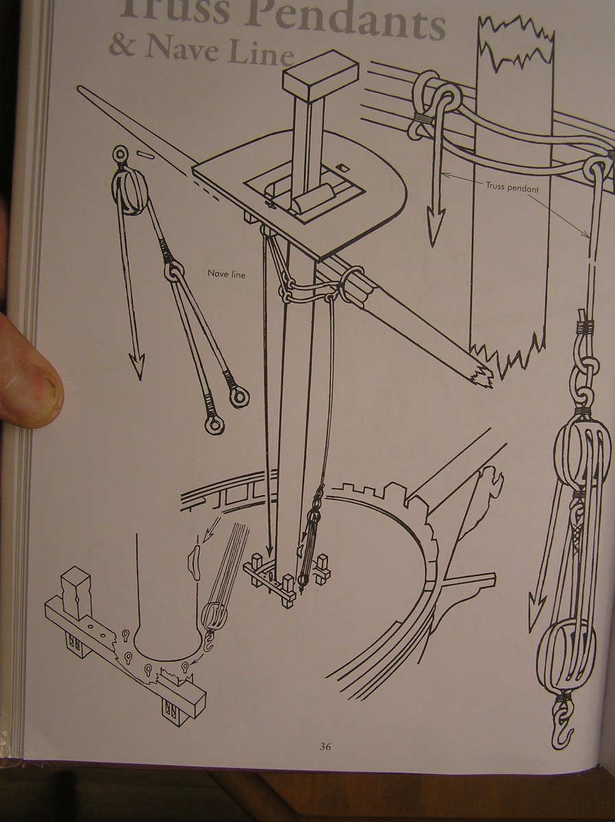
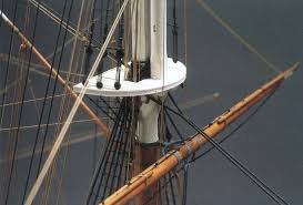
As well as the sling to hold the yard up, something is needed to hold it against the mast when the wind is pushing on the sail. I'm guessing you have your yard pinned to the mast with a piece of bras rod or the like or it would be very difficult to get it to stay in place. In the 18th century this function was performed by rope "truss pendants". In later years, certainly by the time of steam wheelers, they were changed to chains. By the time of the clipper ships they had iron "trusses" which supported the yards and allowed them to pivot. Rope truss pendants....... Clipper ship trusses...notice the curved iron fitting behind the yard, attaching it to the mast.

- 146 replies
-
- 3
-
-
- Harriet Lane
- Model Shipways
- (and 1 more)
-
Yes, the last I read was the sides of the hull were painted a "restful" yellow ochre in the gun decks. Who'd want to live in a red habitation?
-
Bob, re your mainyard, I see the sling, lifts, and braces; but should there also be a truss, or truss pendants (depending on the time period here)?
-
Just curious - what's that big wheel to the pilot's left for?
-
Bienvenidos Alvaro! Looking forward to seeing your models.
-
Well, the topsail sheets are 8in which is represented by 0.5mm lines too, so the course sheets might seem a little small in comparison. Maybe you could you just snip off your .35mm sheets/tack near the hull and push the loose ends in, then take 0.5mm line, push it into the holes and affix with a spot of glue? Then just leave the 0.35mm coils at the stag heads. Or better yet, stiffen the 0.5mm ends with CA, push them into the holes far enough to grab the ends within the hull with tweezers, pull out through the skid beams, tie a large knot, clip off past the knot and pull from the outside until the knot hits the hull? Would be more reliable than gluing the ends into the open holes. Yea, I might do that. Again just leave the 0.35mm coils at the stag heads.
-
Nothing wrong with TinkerCAD. 😄
-
Bill, I really can't say, it's your model. Would be very difficult to reach in and redo the stag's head at the main deck level beneath the gangways. Maybe you could reach in there withbent tweezers. Is the pain worthwhile to you? Conversely, if you leave it, will it bother you every time you look at your model, for years? Certainly everyone else will be oblivious.
-
Bill, these are 7 in. ropes which work out to 0.557mm diameter at scale; looking at my excel I see I mistyped as 0.57mm. I used 0.5mm. If your 0.35mm is truly that you're not ridiculously far off........
-
Looks amazing Chris, but many novels have the men tying their neckerchiefs over their ears for some protection.......I must admit though that they would not look as good............
-
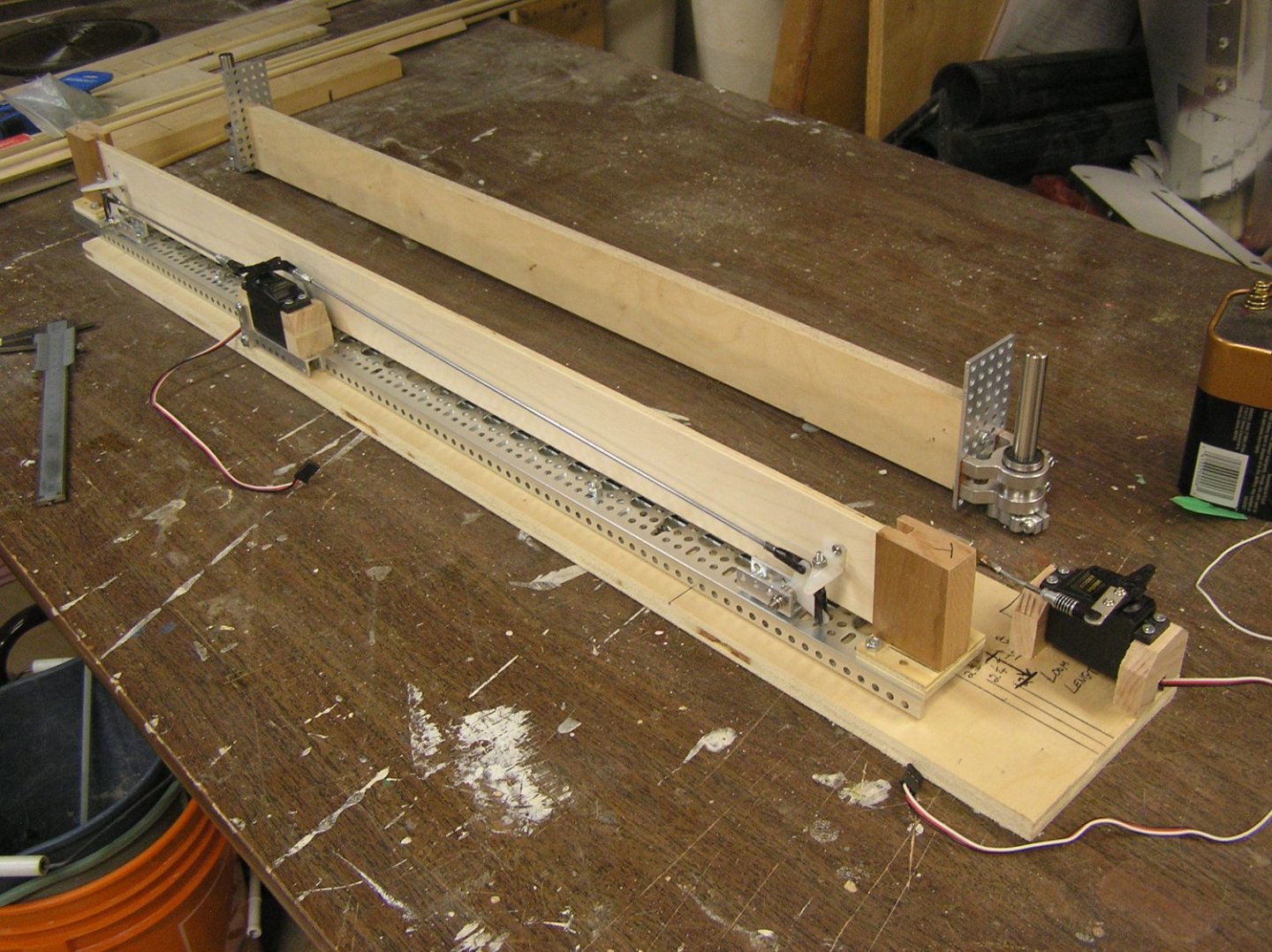
Worries, worries, worries. One step forward and two back. I noticed the oar beam assembly was getting pretty heavy, indeed someone warned me about it in an earlier post. I tossed and turned one night, worried about whether the u/w hull (whose volume I do not know) would displace enough water to support the galley's total weight without sinking too far thus reducing my already paltry freeboard. Ideally it would float above design waterline then I could add ballast. The waterline should bisect the ram. I realized that now that I have the bellcranks moving each end of the beam up and down, a simple dado'ed wood block at each end to allow movement, like in my prototype jig, might suffice. Also, the entire thing was a bit wobbly side to side. The two 17" steel drawer slides have to have some "breathing" allowance in order to absorb tolerances if using them in a drawer scenario. I noticed that they, although 5 inches longer than the 12", only have one extra inch of actual ball-bearing cradle. I decided to replace the 17" slide under one side of the channel with two 12" models. This helped considerably. I didn't replace the other side since there are mounting bolts for the bellcranks etc in the way and I didn't want to change everything. Here is a pic of the new structure, with the old beam and attachments in the background. The weight of the removed metal parts is significant. The most significant factor in the assembly's weight is now the steel drawer slides which are about at waterline. I want to keep the aluminum channel at the base because it will never warp or twist. The up/down movement works well even without my patented packing-tape "lubrication" on the beam. The beam can be thinner/lighter since I am no longer screwing into its ends to attach metal plates. It's flimsier laterally, but the hardwood strips for oar attachment will keep it straight. On the right end is a sweep servo, still just a regular type not the "giant" which will be in the boat. Now that it has occurred to me I am still worried about displacement. I plan to weigh my battlecruiser, which as I said is a comparable size to the proposed galley, both empty and ballasted to waterline (have to borrow a neighbour's pool since the falling tree destroyed ours). Assume the empty galley weighs about the same as the empty battlecruiser: if this additional ballast amount is less than the weight of two oar drives then I am in trouble. Each 1/4" added to the galley's draft would give on the order of 60 cubic inches additional displacement, or about 2.2 lb. I may have to carve a replica of the lower hull to measure its displacement. Or I just add 1/2" to the draft. Bedford commented earlier that maybe I could "square off" the bilges to create more buoyancy; that may be an idea. But the only galley lines I have are for the "Olympias" and I don't have the 3D tools knowledge to make serious changes. But there's always prototyping hull lines with card bulkheads 🤨. In the meantime, on to oar-making! I've given up on the 3D print idea, far cheaper to just use wood.
- 536 replies
-
- 4
-
-
- Quadrireme
- radio
- (and 1 more)
-
Really looking forward to seeing how you make the cattle! Maybe you could place sheep in the other pen, and have a penguin as a shepherd 🤣. (for those folks who don't get it, you need to read some of Glen's previous logs).
- 194 replies
-
- 4
-

-
- Bottle
- Treasure Fleet
- (and 3 more)
-
You're right. Suggest you buy a copy of RC Anderson's "Rigging of Ships In the Days of the Spritsail Topmast" for rigging guidance on SR. Since little is definitively known about her, you can please yourself!
-
I'm absolutely, totally impressed by both these models! I must try a card model sometime. As a kid I was interested in WWI planes but I never wondered about something this model brings to mind: looking at the Lewis gun, and recalling that the SE-5A had a gun up there too, did the pilots actually have to reach way up there to pull the trigger all while flying the plane in a dogfight no less?! Or did they pull a string? 😄
- 98 replies
-
- 12
-
-
Bill, those are your sprit topsail's clew line blocks. You don't need the two lines attached to their arses. Instead, the clew lines come from their belay points on the forecastle, and pass through the blocks. Normally they would be attached to your (absent) sail's clews, along with the sheets which also belay at the forecastle. However, without a sail, you just attach the sheet to the clew line and end up with just a little loop from the block to the forecastle. In practice I just used a single piece of thread to depict both. Longridge lists the clew lines, stating that they are single, on pg 239 but they (and the sheets) are totally absent from the belaying plan (as are the spritsail sheets and clew lines)! Being single, there is no block at the clew of the sail. Just the ones on the yard. Rigging the sheets to an outer timber head and the clew lines somewhere inboard of them makes sense. Your spritsail yard is out of focus so I'm not sure what you did for its clew lines and sheets. In its case, the clew lines are double ie there is a block on the yard and a block at the clew. Looking at the big rigging Plan 7 we see these pairs of blocks just dangling beneath the yard because there is no sail. As Longridge describes on pg 237 the clew lines are attached to the spritsail yard, pass through the lower block then the upper block and then to the belay point (which you have to make up your own mind on). Rigging without a sail, the sheets would attach to the a*se of the lower block (HAHA when I submitted this reply it didn't like the word ar*e 😆). Confusingly, he seems to have the sheets leading in above the middle gun deck's 2nd port in Plan 7, even though he states on pg 238 that they "lead in on the forecastle". He has also drawn similar pairs of blocks dangling from the sprit topsail yard even though he states, as mentioned above, that its clew lines are single which makes sense since this is a much smaller sail. These extra blocks seem to be an error in plan 7. Hope this helps. You're nearly there! Looking forward to seeing what you make of SR next! My SR will be waiting a while yet........ PS: Agree with Veszett about your nice ratlines, but did you remember to tie them on the futtock shrouds too? 😃
-
I really enjoyed your build log, Richard. Producing such a fine machine from rough castings is an accomplishment to be proud of! My grandfather was a machinist in the Clyde shipyards and my dad did his toolmaking apprenticeship at Rolls Royce. I was fortunate in going to a high school with extensive shops all of which I loved but particularly machine shop. In grade 11 I announced that I too wanted to go into the field, but dad discouraged it, saying he wanted something "cleaner" for me. I ended up doing something else, with better pay, and ended up with wood as a hobby. When dad passed I kept all his old tools, like his 1-2-3 blocks, V-blocks, and other doodads he made but the only things I have occasion to use are the micrometers and calipers. My son has no interest or experience so I guess when I go they may end up in an antique shop. 😢
-
Soleil Royal by yancovitch
Ian_Grant replied to yancovitch's topic in - Kit build logs for subjects built from 1501 - 1750
Vic, she looks great! Totally believable underwater hull, vastly superior to Heller's. -
Hi Bill. When going into a classic battle they reduced to "fighting sail" mainly topsails, with lower sails at least clewed up because of the danger of their catching fire. The driver is partly brailed up. I don't see the driver boom so I wondered if this depiction is of Victory before her "great refit" when she still had the lateen mizzen lower yard; but I don't see its forward portion either. On the other hand, she seems to not have the black and yellow ochre colour scheme of later years. Also unable to make out if the stern has the galleries or not; these were present as built but closed in after her refit. I agree the mizzen topsail looks odd. Could it be she has lost the mizzen yard and the topsail is blowing free? If so it's an odd looking shape to take. I seem to be raising more questions than answers. Funny how painters commonly filled in battle foregrounds with men in boats. Any idea which battle this is?
-
Yes the Heller instructions are truly terrible. I found your build log; you sir now have a new follower!