Ian_Grant
-
Posts
2,156 -
Joined
-
Last visited
Content Type
Profiles
Forums
Gallery
Events
Everything posted by Ian_Grant
-
 Jeff, looking good so far! I'm always pleased to see another Heller Victory being built, it is a very special kit despite its shortcomings in rigging instructions. There are several Victory logs on MSW, the most recent by BILL97. You would be well advised to read through his log as you progress; there are many faults with the Heller instructions especially pertaining to rigging and some things you need to add to, for example, the quarterdeck in order to be able to rig properly in later stages. But rather than detail all these for you here, the information is all in Bill's log. I have a few general recommendations, in the meantime. 1) Forget Heller's deadeyes, they are impossible to rig without a groove around their periphery. Buy some after-market wood deadeyes. 2) For rigging, a copy of "The Anatomy of Nelson's Ships" by C. Longridge is indispensable. It contains detailed info for each rigging line including rope and block sizes and has many many helpful diagrams. 3) Brass etch parts are available for this kit. I highly recommend the chains and stanchions. Heller has no representation for the chins beyond loops of thread and their stanchions have no eyes so are difficult to rig. Looking forward to reading about your progress.
 -
Never heard anyone mention about them leaning forward. Are the aft edges of your decks properly aligned with the transom ends of the hull halves? Are the masts mating with the steps at the keel? At any rate yes, you'll have to correct them by filing. Foremast should be vertical, mainmast slightly raked, mizzen a little more so. There is a known issue with the mainmast openings; one of the them is out of kilter I think it was the middle or quarter deck. This needs to be filed. You are wise to be checking alignment as you go! A
-
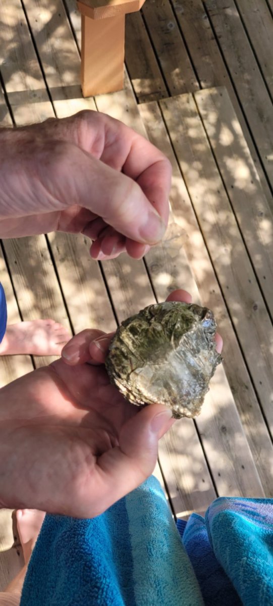
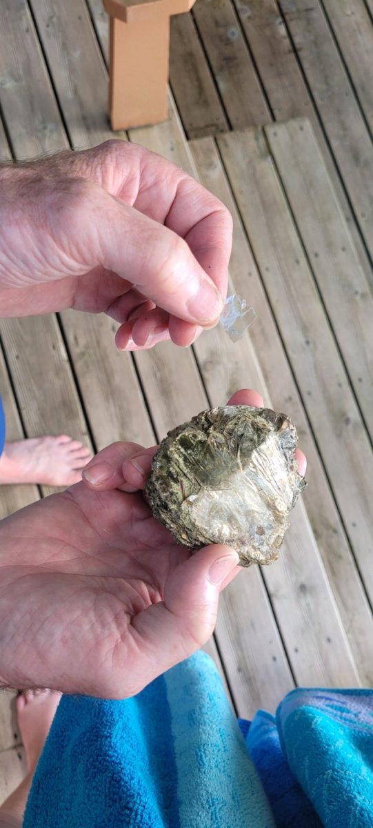
Funnily enough, there are chunks of mica just lying on the ground all around our cottage. There was once a mica mine in the hills across the other side of the access road. Every time we dig a post hole we find more. The kids used to be fascinated by it, peeling it apart endlessly. I used to joke about going into production of capacitors. If ever EV batteries need mica, we'll be RICH!! 😆 LATER EDIT: Was at the cottage this weekend; here are a couple of pieces of mica I picked up. The one in my left hand is small, but so thin and clear you can hardly see it in the shot.


-
Bill, If you furl sails the clewlines and buntlines remain attached and disappear into the folds. There are examples of this here on MSW. Don't forget the bowlines if you want to be detailed! Yes, I omitted sails but I didn't want to simplify the rigging too much, lest ship handling appear simple to the viewer. The clewlines I attached to the sheet lines which they would have met with at the corners of the sails anyway, as is common practice (this is what Longridge has drawn in his large running rigging diagram). The buntlines I passed through their blocks on the yard, then hitched to the yard. Similarly, I rigged the bowlines and bridles, with ends hitched to the yards. Also common practice.
-
Glen, maybe you could split the hull not along the keel line but to one side of the mast holes. Might be harder to conceal the join though.
- 194 replies
-
- 2
-

-
- Bottle
- Treasure Fleet
- (and 3 more)
-
Good approach to it, Glen - like NASA testing a new rocket in baby steps. I have to ask - how will you press the hull halves together and get no glue squeeze-out in the mast holes?
- 194 replies
-
- 2
-
-
- Bottle
- Treasure Fleet
- (and 3 more)
-
Looks great Bill! Now you get the pleasure of trying to paint those darn lanterns. 😉
-
Yes, it's a shame how gaming has taken over. A friend who used to teach high school Auto Mechanics says in the old days (70's) boys arrived having a rough idea of what a differential did; now they don't know which way to turn a nut to tighten it. 🙄
- 536 replies
-
- 2
-

-

-
- Quadrireme
- radio
- (and 1 more)
-
You can get adhesive vinyl lettering in various colours and sizes, made by BECC. In fact, "Cast Your Anchor" near you in Toronto carries some.
- 200 replies
-
- 1
-
-
- Whaling Bark
- Charles W Morgan
- (and 1 more)
-
Our 2004 Sienna had the spare suspended under the vehicle which struck me as a stupid way to handle it, in road-salted Canada. Apparently there was a crank hidden somewhere under the carpeting near the 2nd row seats, which when turned lowered a "cage" holding the wheel, to the road. Luckily never needed to use it. Colour me surprised, there were two recalls over the years to replace the chain that held the wheel up off the road due to rust causing wheels to fall out. A while ago, I mentioned to my wife that we should get it checked out again, but she replied, "Oh, there's no wheel there any more", which was news to me. Apparently, she was coming home on the 401 from a trip a few years previously, and when she pulled out of her parking spot at a highway rest stop the wheel was lying there. So she just continued on her way and never thought to mention it!! 😆 😆
-
Thanks Bedford; yes I had worries about two y-harnessed lift servos on one beam moving the same amount in degrees. Not sure of consistency to be expected of a given model of servos. Plus there were the problems of where to mount them. Back to four servos total again, which is easier. I can easily adjust the linkage lengths to make both ends consistent.
- 536 replies
-
- 2
-
-
- Quadrireme
- radio
- (and 1 more)
-
Hi Glen, yes as a matter of fact I played with Meccano for years including the Meccano "Electrikit" which had coils powerful enough to induce metal rods to move, thus actuating models. Laid the ground for my engineering career. I still have all my old meccano; I kept it around hoping to introduce my kids to it but of course most kids nowadays are not interested. 😢
- 536 replies
-
- 1
-
-
- Quadrireme
- radio
- (and 1 more)
-
Working on a full-size oar beam with the plan to make another mock-up like my first one, but with only one side and all 44 oars. Need to make sure I can build it without oars clashing. I thought more about the lift mechanism and woke up one morning with the idea to have a single lift servo push both ends of the beam up and down, analagous to the aileron hook-up in an RC plane. Took a while to gather parts and assemble as my motivation has gone over a cliff in the hot weather. Speaking of which, I still have not had a single sail on my dinghy at the cottage. Spring was pretty cool and I never had anyone there capable of helping me lift it up and into the water. Finally had a chance two weekends ago on a beautiful windy day. I rigged her, sailed a few yards from our dock, and the tiller extension U-joint broke 🙄. As this boat went out of production in 1980 the U-joint didn't owe me anything! There are no boat parts near the cottage. Fixed it at home but last weekend there was no wind 😭. Anyway here's a video my son shot for me, of the vertical movement. The lift servo on the inboard side of the beam has a link going to each end. These drive bellcranks whose other arms have linkages to linkage horns on the beam. The two bellcranks move in complete symmetry, being driven by symmetric holes in the servo arm. The lift servo is offset from centre so that when I build another identical beam for the other side, the two lift servos will not be opposite each other and so will not interfere.
- 536 replies
-
- 3
-
-
- Quadrireme
- radio
- (and 1 more)
-
Thanks Richard. I saw that line on the drawing about the two different scales but I couldn't make any sense of them on the 8-1/2"x11" printed sheet. I guess his actual drawing was much larger, about 400mm across the beam, evidently. Bought some heavy paper to mock up hull bulkheads once I have some proposed cross sections.
- 536 replies
-
- 1
-
-
- Quadrireme
- radio
- (and 1 more)
-
I have to ask - is that wheel in front just welded on to give the battering ram some more heft? I can't imagine that it's a spare plus there are no bolts or straps........🤔
-
Glen, looking forward to being amazed by your miniaturization of this "farm".....
- 194 replies
-
- 3
-
-

-
- Bottle
- Treasure Fleet
- (and 3 more)
-
Soleil Royal by yancovitch
Ian_Grant replied to yancovitch's topic in - Kit build logs for subjects built from 1501 - 1750
She looks superb Vic! I couldn't do that with non-shaky hands............ -
Same with my model planes in the 80's oops I meant in the 70's. They always ended up with an oil mess on the nose and at the wing roots. Don't know what it's like now; I've seen some amazing model plane engines ($$$) at the hobby shop nowadays, 4-strokes with valves...
- 98 replies
-
- 11
-
-
Amazed that that's all the pilot had to sit on - a backless (or nearly so) chair with a lap belt! Not much more evolved than a tractor seat.
- 98 replies
-
- 11
-
-
Yet another new note on my SR instructions, along with the recently mentioned bowsprit steeve.........for when I get there.
- 2,699 replies
-
- 4
-
-
- heller
- soleil royal
- (and 9 more)
-
Impressive! Did you have to fold up that hull somehow, or does it come formed?