HOLIDAY DONATION DRIVE - SUPPORT MSW - DO YOUR PART TO KEEP THIS GREAT FORUM GOING! (78 donations so far out of 49,000 members - C'mon guys!)
×


FriedClams
-
Posts
1,368 -
Joined
-
Last visited
Content Type
Profiles
Forums
Gallery
Events
Everything posted by FriedClams
-
 Great looking new project, Ras. Lots of interesting details and structures to model. This will be interesting! Best of luck. Gary
 -
Nice progress, Keith. Great little structure and fully framed to boot! Gary
- 732 replies
-
- 4
-

-

-
- Lula
- sternwheeler
- (and 1 more)
-
Hey Keith, now that's an idea! Wonder if I can find a used one somewhere? Yes Druxey, AutoCAD has been known to have that effect on people. I use DesignCAD for my 2D drawing and have for decades, but for 3D modeling I prefer FreeCAD over it and a number of other alternatives. I think it's a very good solid modeler and a decent surface modeler. There are many good "free to use" programs, but with FreeCAD you download it once and its yours forever; no logging on to a website, registering or having to use it in the cloud. And no concerns that after investing the time to learn a program, the company granting you free access might change the rules and make you a subscriber or a previous user. FreeCAD certainly has its quirks and weaknesses, but so do the alternatives. And I'm not a power user - I just want to make a few parts for my models. Extensive online tutorials and help is available. I found YouTuber MangoJelly Solutions to be a great help. Be safe everyone and stay well. Hope to have a Pelican update this week. Gary
-
Brig Le FAVORI 1806 by KORTES - 1:55
FriedClams replied to KORTES's topic in - Build logs for subjects built 1801 - 1850
Good to see an update, Alexander. Beautiful work as always! Gary -
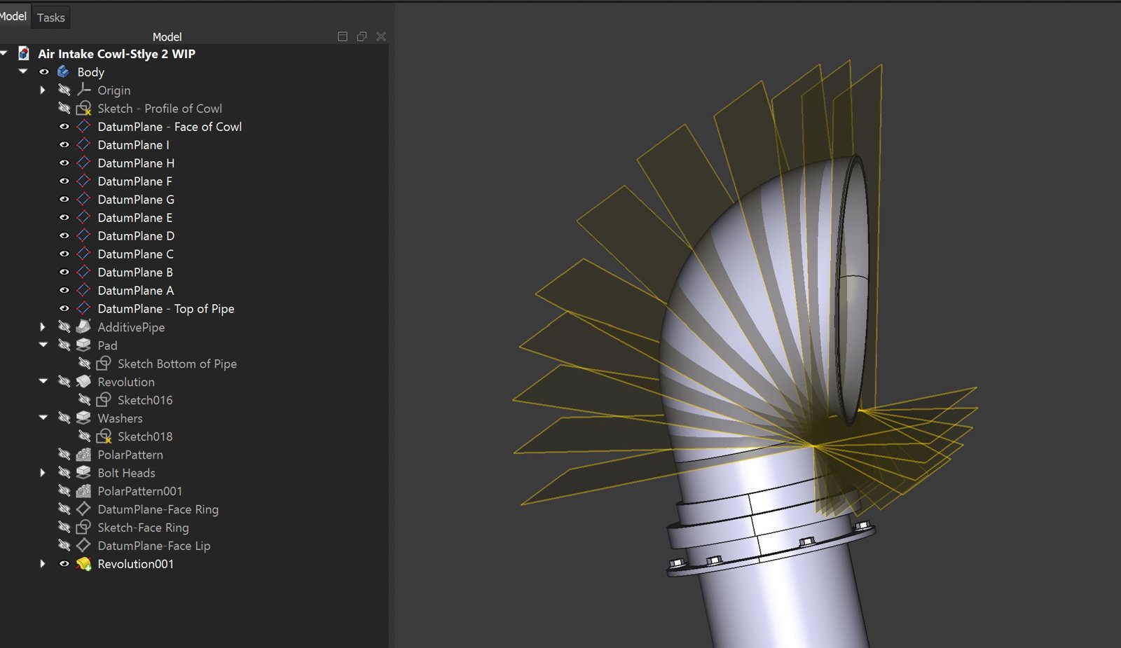
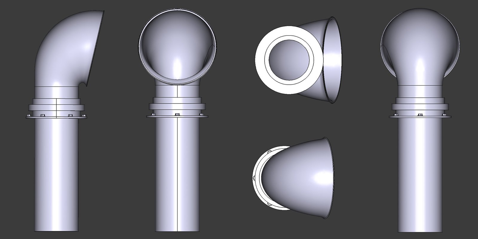
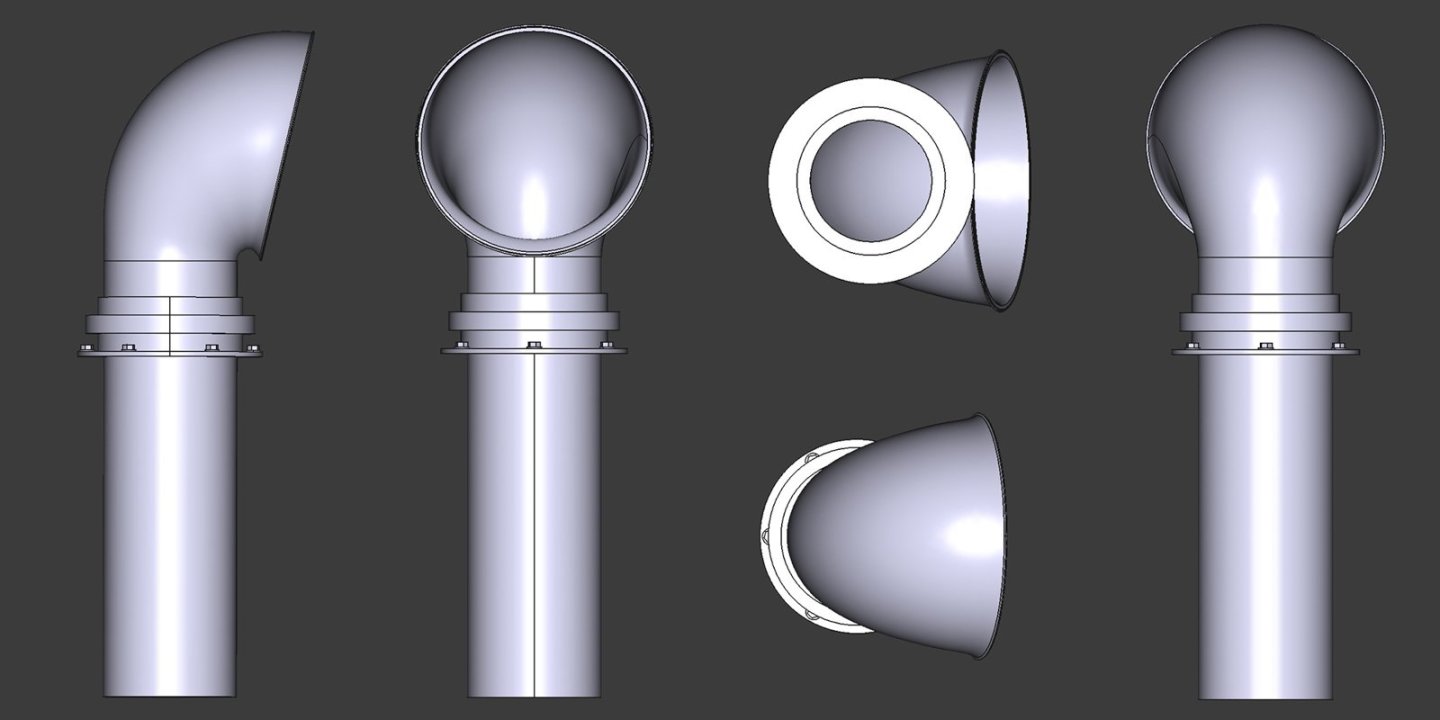
Thanks to all for the comments and the "likes" Thanks Paul. It's actually an enjoyable process and the SLA technology does a great job of reproducing details and a smooth surface finish. Hey Jacques, that does sound like a good option and it's wonderful those resources are available to everyone. But I'm in a rather rural spot and a population center large enough to support something like that is some distance away. Thanks for bringing that up though as I'm sure it will be useful to other MSW members. Hello Druxey. Because this was my first serious go at it, it took a heck of a long time. I had so many "how comes", "why nots" and "what ifs" to understand and I deleted and started over many times. These are very simply objects and an accomplished 3D modeler could complete these before I even got started. But now that I have the false confidence of a beginner, it takes me a quarter of the time it did starting out. And of course, some designs are easier than others. In example, the simplest designs would be the gypsy heads which are cross-section sketches followed by a revolve - on a good day, 10 minutes. The winch cable guides, 45 mins. Winch drum and brake drum, 30 mins each providing I don't mess up. But by far the most difficult was the intake cowl as it entailed setting up user defined datum planes upon which cross-sections of the cowl are sketched and are then swept together in an additive pipe function. It sounds way more complicated than it is, and an experienced modeler would likely chuckle at my approach. Nevertheless, it took me hours to figure out, tripping and stumbling along the way and now that I almost know what I'm doing - an hour and a half - maybe. Once I got my head around 3D space and user defined coordinate systems within the global coordinate system, the steam stopped rising out of my ears. Thank you, Keith - your support is always appreciated. Thanks, John - they turned out better than I thought they would. Hello Wefalck. I am the one who is confused, not you. You are correct - this is SLA process using resin not PLA. Sometimes I type faster than I think. I will correct that in my post. Good catch and thanks! Gary

-
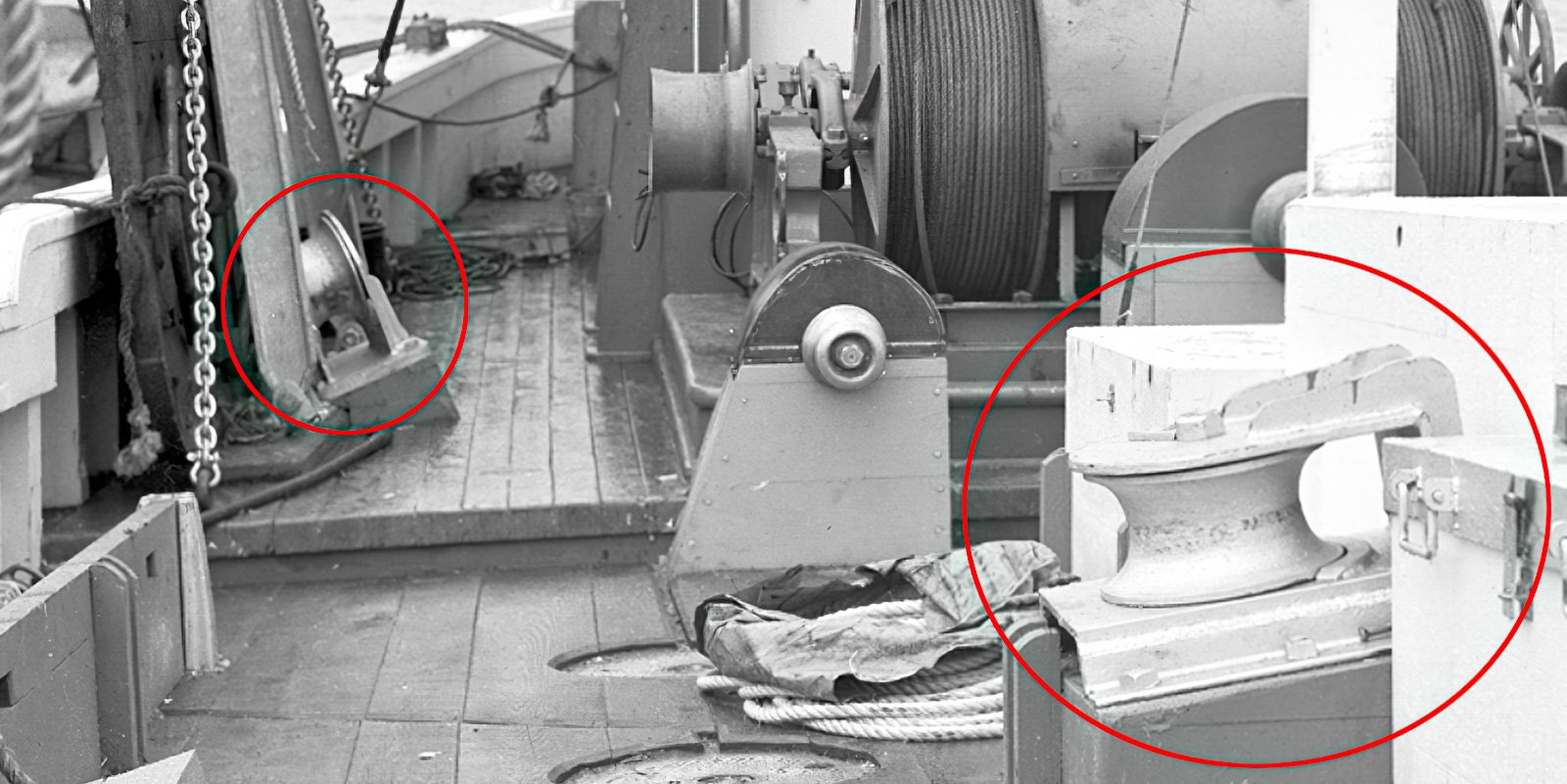
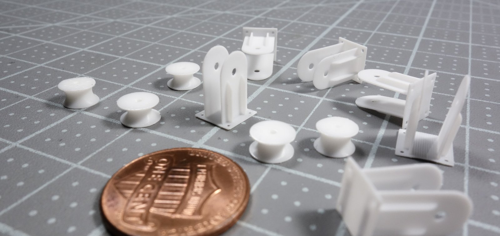
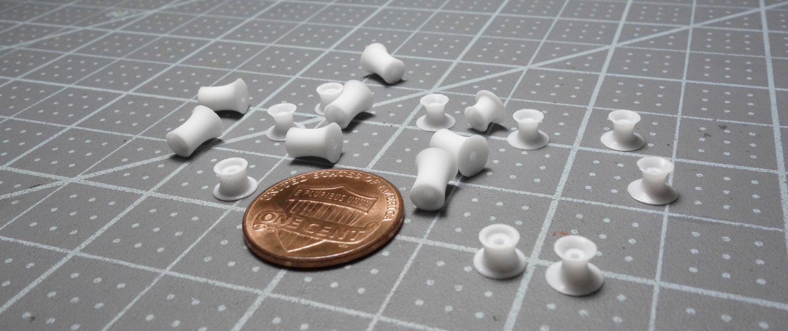
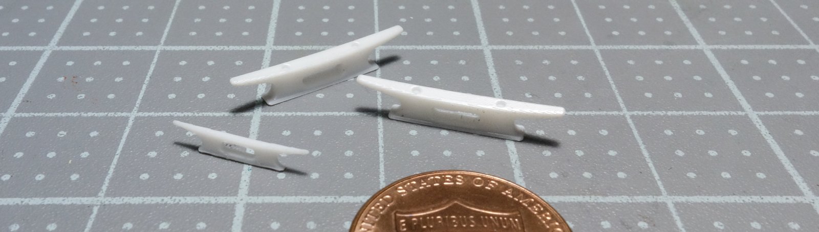
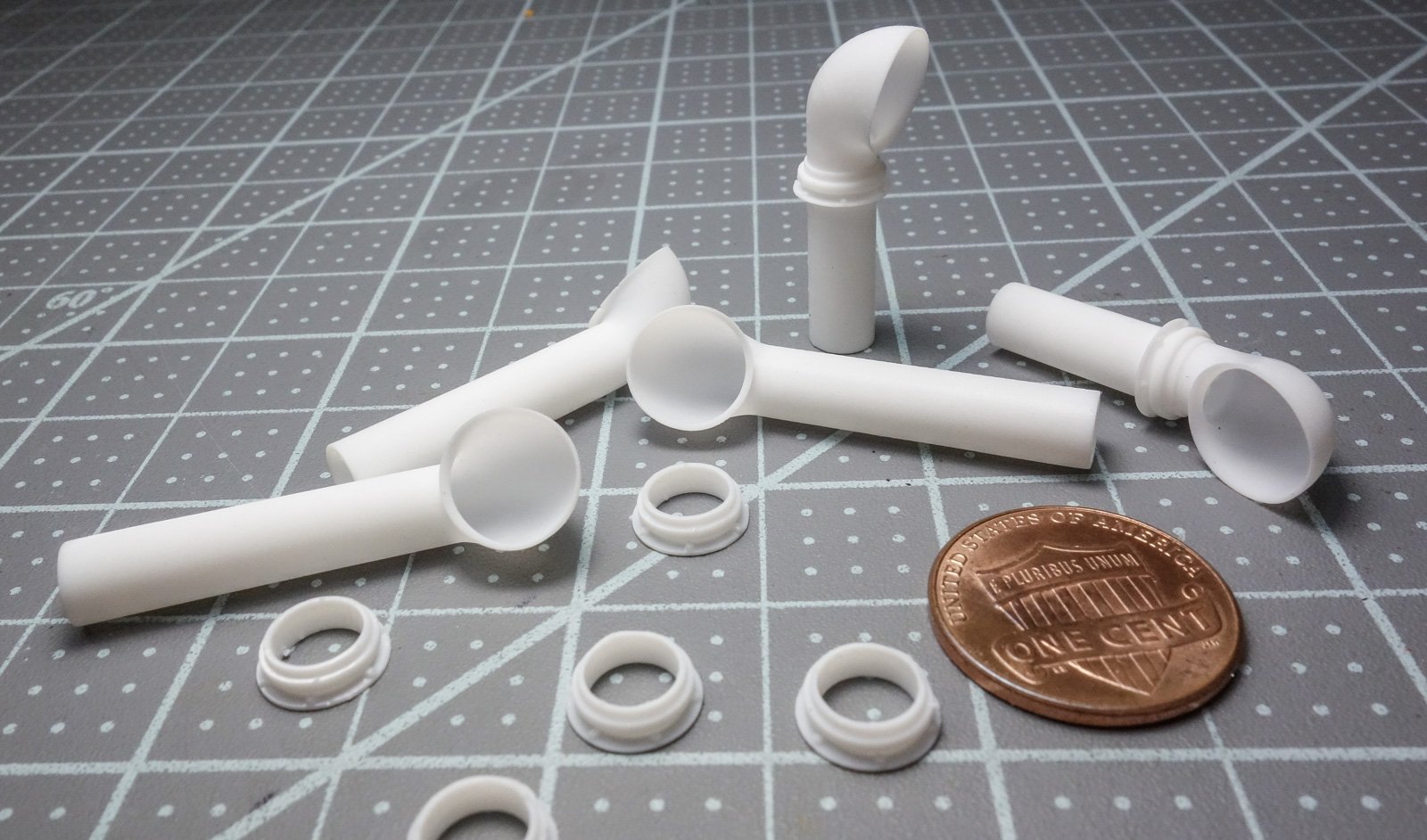
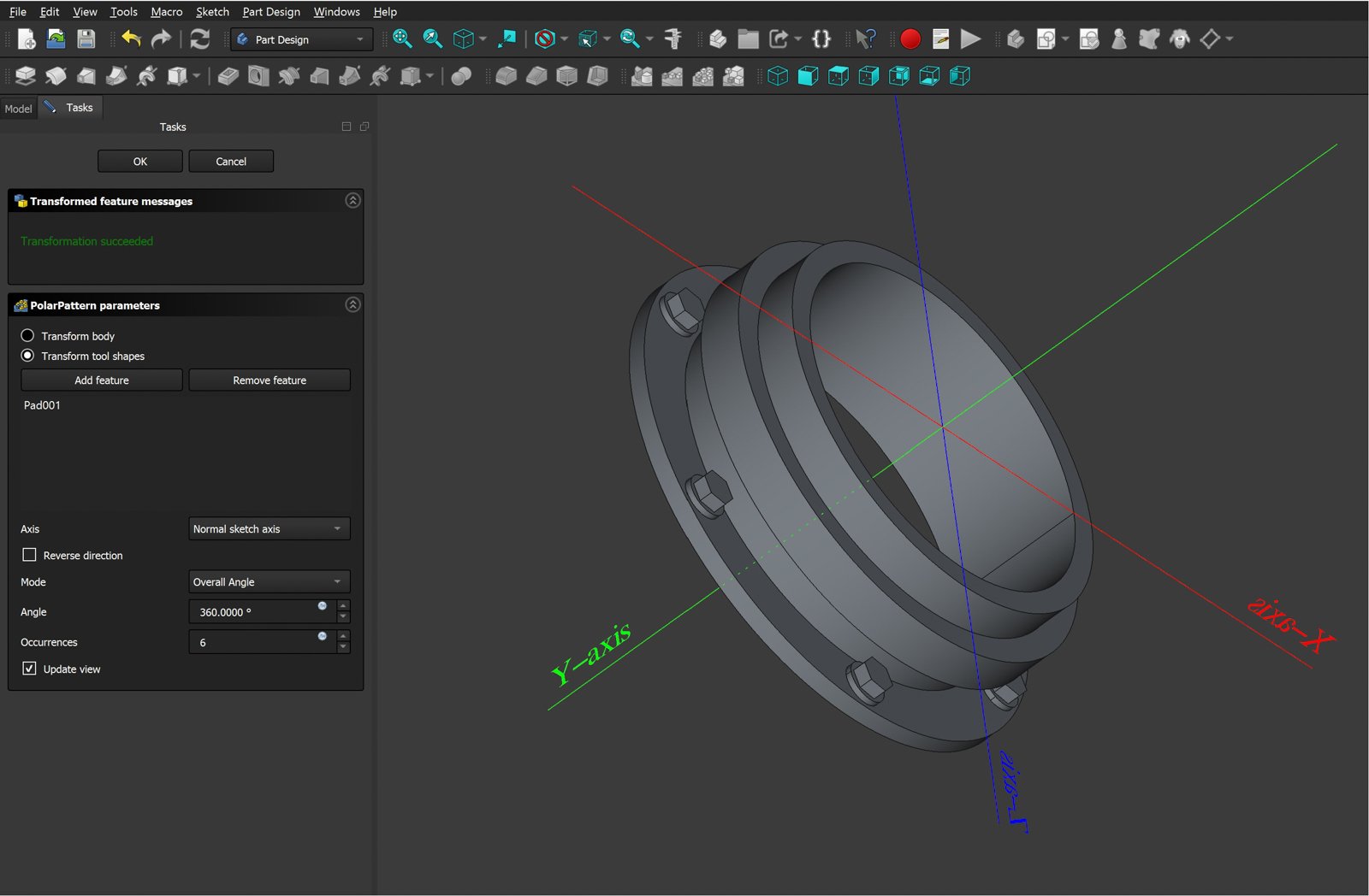
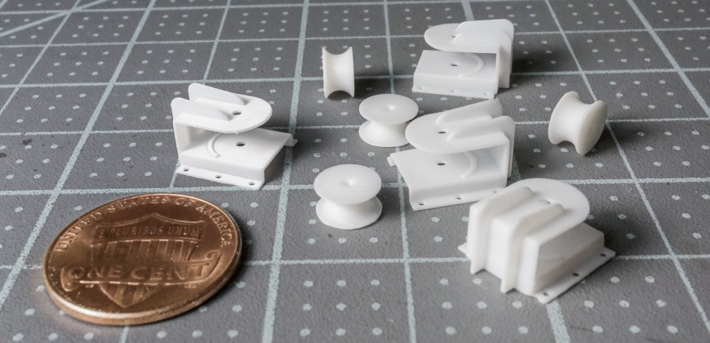
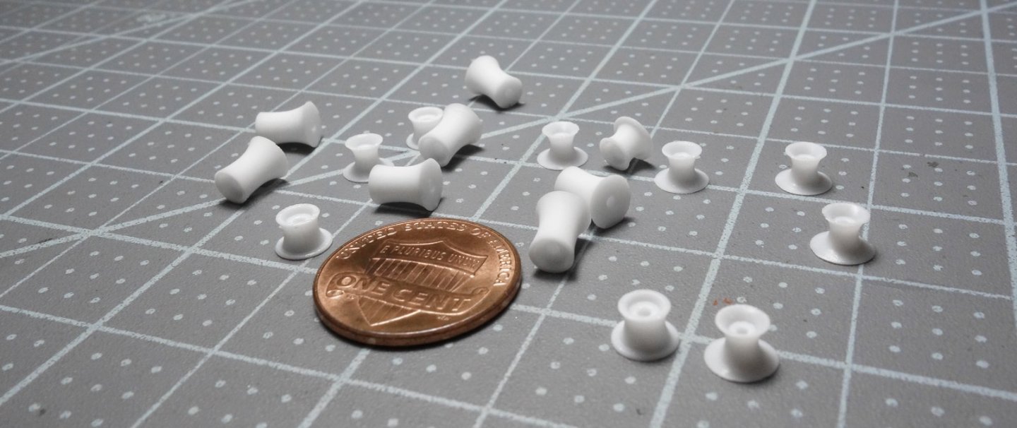
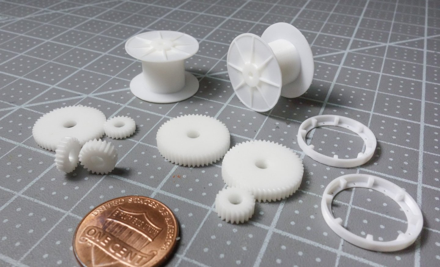
Paul, Keith, John and Dan, thank you for your kind and generous comments and to all for the "likes". 3D modeling seems to be popping up everywhere in scale model building so it’s time to give a try. I’ve always enjoyed the process of hand scratching detail parts, and I have no intention of giving that up. But I’m also aware of my limitations and previous projects have suffered from some ham-handed constructions and 3D modeling will help solve this problem. So, the Pelican will be a mix of printed and handmade details. I designed all the printed parts used in this model specifically for the Pelican. It is solid modeling done with FreeCAD. I created the files but didn’t do the actual printing myself. I don’t see myself using a 3D printer enough to justify owning one, but that could change as consumer units continue to improve and drop in price. Anyway, I uploaded all my STL files to a commercial printer (Print a Thing) and the parts were delivered in less than a week. The total cost for these printings was around $33 US including shipping, tax and setup fees. I ordered extra copies of each part thinking some might be deformed due to their tiny size and fragility, but this was unnecessary. These are likely all the parts I’ll be printing for this model unless I run into trouble scratching something. So here they are and just as I received them. No cleanup has been done to them. Stereolithography (SLA), opaque white resin. Below are the deck mounted winch cable guides. It would have been an effort to scratch one of these from styrene let alone four of them identically. I left off the bolt-down washers and hex heads because they wouldn’t have printed well in this scale. Instead, I’ll place injection molded bolt heads from either Grandt Line or Tichy Train. Here they are on an actual dragger (circled on the right). Above on the left is a different cable guide under one of the four gallows frames. There are three different warping/gypsy heads. I have about 14 cleats of several different sizes. The two largest shown here are monsters (40” (102cm)) that bolt to the deck on top of the whaleback. I didn’t realize cleats were made that large. This is another example where making two precisely the same would be a challenge – as least for me it would. The main winch cable drums, brake drums, pinion and bull gears. I only need one each of the gears, but I created different width versions because I haven’t thought through the details of the winch yet. The spooling drum diameter is very large in relation to its flanges, and I did this to reduce the amount of cable I’ll have to wind. And finally, the air intake cowls. The forward cowl has an integral mounting and rotation flange, but for the engine room intake I created the flange separately so I can adjust the height as need be. It’s the same cowl with a longer duct pipe. I added hex bolts to these flanges and with the naked eye they look alright, but under magnification look more like rivets. My initiation into 3D modeling design was a positive experience and only left a few minor scars. It is rewarding to create parts unique to a project that could have been a real pain to make or at least to make well. There is certainly a learning curve with 3D modeling and at times I was perplexed. But eventually all the loose marbles in my head found holes to drop into and the light bulb turned on. It’s easier than you might think. Now back to the boat model. Thanks for looking. Gary


-
Great progress, Craig. Looking extremely nice. Gary
-
Nice progress on the Constitution, Glen, really like the J. Ladders. Good news on the award but so sorry to hear about that bottle crack - what a bummer! I’ve heard downing a half bottle of Sailor Jerry can fix that. Gary
- 301 replies
-
- 3
-
-

-
- Constitution
- Bluejacket Shipcrafters
- (and 1 more)
-
Very nice work on those steam engines, Keith. That’s difficult modeling- putting two things side-by-side and making them look the same. Good to hear you’re putting a dredger on the to-do list! Gary
- 732 replies
-
- 6
-
-
-
- Lula
- sternwheeler
- (and 1 more)
-
Congrats on a very nice SIB, Roel! I agree with Glen, a unique subject and a quality build. Gary
- 70 replies
-
- 4
-
-
-
- Scheldt River
- Dredger
- (and 2 more)
-
Phil - S scale is 1:64 so an S scale 1" x 10" is equivalent to 1/64 x 5/32. Mt Albert Scale Lumber in Canada sells S scale lumber in 16" lengths and is available in bulk pricing (minimum of 50) if you need a bunch. Scroll down at the link below to see dimensions. https://handlaidtrack.com/product/stb-s-1x10-16/?v=0b3b97fa6688 They also sell packages of 6 if you need just a few. https://handlaidtrack.com/product/st-s-1x10-16/?v=0b3b97fa6688 Gary
- 459 replies
-
- 2
-
-
- minesweeper
- Cape
- (and 1 more)
-
Nice progress and recovery on the rahschlup! I've learned that mishap mitigation is an important skill in modeling. Gary
-
Excellent progress, JC. And it bears repeating - beautiful job on the planking. Gary
- 312 replies
-
- 4
-
-
-
- Chile
- Latin America
- (and 6 more)
-
Nice work, Roel - looking very good. Interesting - never thought about that. Gary
- 70 replies
-
- 2
-
-
- Scheldt River
- Dredger
- (and 2 more)
-
Dang - beautiful indeed, Valeriy! My only complaint is that you built it too quickly leaving us wanting more. Extraordinary modeling! Gary
-
Terrific tiny work on that wheel, Keith! Are you sure this is 1:120? I also would like you to do another working sternwheeler - we all would. Better get started on the research. Gary
- 732 replies
-
- 6
-
-
-
- Lula
- sternwheeler
- (and 1 more)
-
Congratulations on starting a new project, Paul. This is an interesting and eye-catching subject and I look forward to watching you bring her to life. I haven't taken a look at the HAER plans for this vessel, but typically they are rather complete, and I hope they don't leave you having to guess at too much. At 36" and with such a complicated pilothouse/quarters structure this strikes me as an ambitious project. I'm pulling up a chair and wishing you the best of luck. I know this is going to be a fantastic model! Gary
-
Very nice work, Håkan! Gary
-
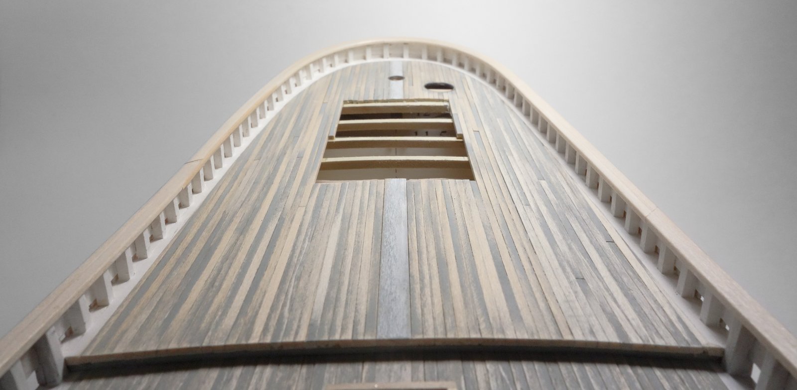
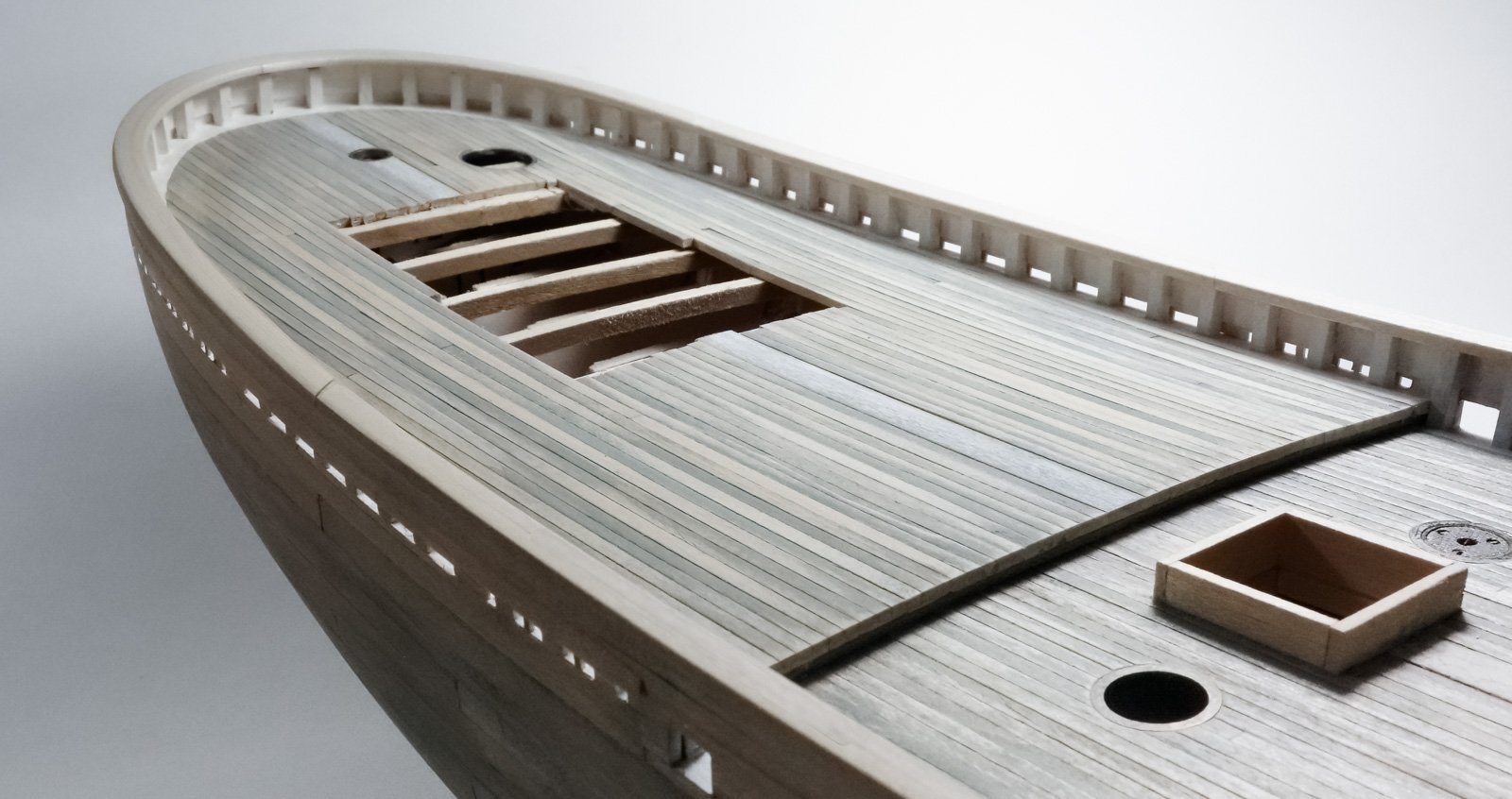
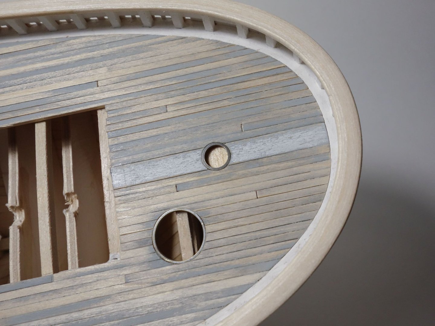
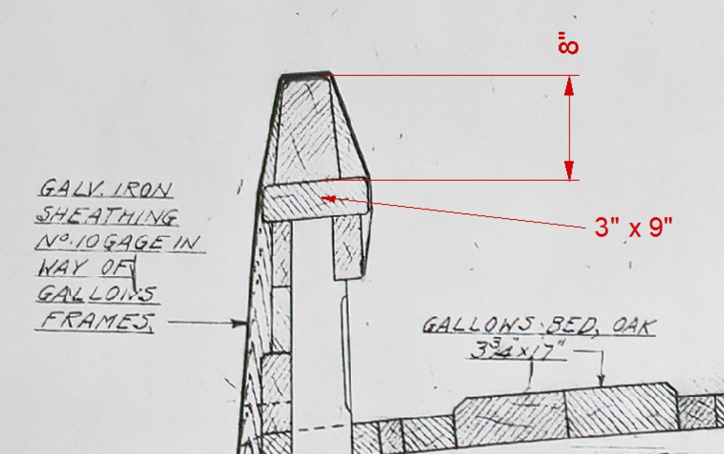
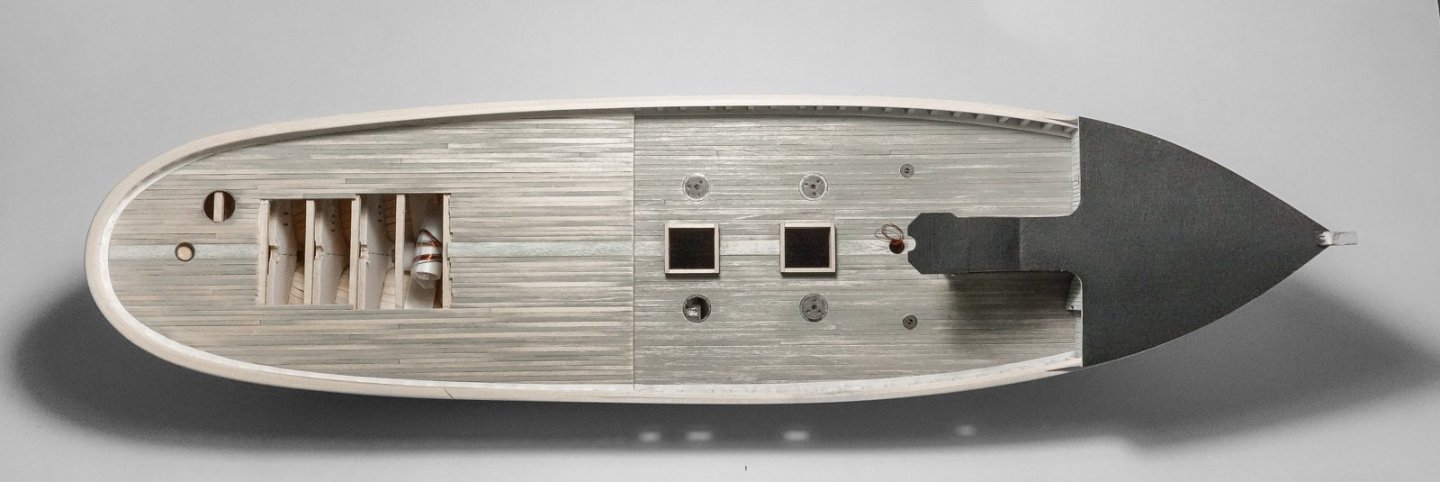
Thank you, Keith, Glen, John, Paul and Druxey for your kind comments and to everyone for hitting the "like" button. It is great to have your support! A quick update. Before continuing on with the whaleback, I backtracked and completed some basic boat work aft of midships that I should have done earlier. This work includes the covering boards, the main rail and deck planking. My process is not explained here because I’ve bored you with all that in a previous post when doing the forward deck. One item worth mentioning is the rail around the stern that I laminated from eight thin strips and a significant amount of PVA. The deck has been rough sanded but will need additional smoothing, scraping and coloring in due course. A scale 26” (66cm) diameter brass ring frame has been installed to receive a lazarette cover and also a 12” (30.5cm) ring frame for the access plate above the rudder stock. The break deck sits 8” (20.3cm) higher than the forward deck and will eventually be fitted with an 8” extension cap. And a couple of overall photos. So, with that done and off my mind, I’ll be returning to the whaleback for detailing. Be safe and stay well. Gary


-
Good to hear your wife is doing well in her recovery, John. Klondike's hull is coming along nicely. It's always a good feeling when the hull sanding is done. Gary
-
Excellent progress, JD - she's going to be beautiful. Gary
-
Been reading through your log, JC and have enjoyed the historical background and research that you've provided. Thanks for that. Regional boats built for specific needs are typically designed for cost effectiveness and ease or repair, but I'm often amazed at how charming they can be. This new project of yours is such a boat, and you're doing a great job on it so far. Keep at it. Gary
- 312 replies
-
- 8
-
-
-
- Chile
- Latin America
- (and 6 more)
-
This sharpie model of yours is just wonderful, Paul and she presents gracefully in the final glamour shots. Congratulations. Every detail of her construction was carefully and cleanly executed. Excellent work by anyone's standards and you should be rightfully proud. Knowing this was your first scratch build quite frankly blows my melon. You were obviously a gifted modeler before this project, but now you've gone and raised the bar on yourself. BTW, your log was interesting and informative as well, and whatever you decide for the next project, I do hope you share it with us. Gary
- 201 replies
-
- 6
-
-
-
- Oyster Sharpie
- first scratch build
- (and 1 more)
-
Been reading through your log, Roel and just caught up. As others have already stated - fantastic detailing in this tiny model! The photos of this project with your Chaconia in the background creates quite the juxtaposition. It makes me smile. Excellent modeling! Gary
- 70 replies
-
- 5
-
-
- Scheldt River
- Dredger
- (and 2 more)