FriedClams
-
Posts
1,368 -
Joined
-
Last visited
Content Type
Profiles
Forums
Gallery
Events
Everything posted by FriedClams
-
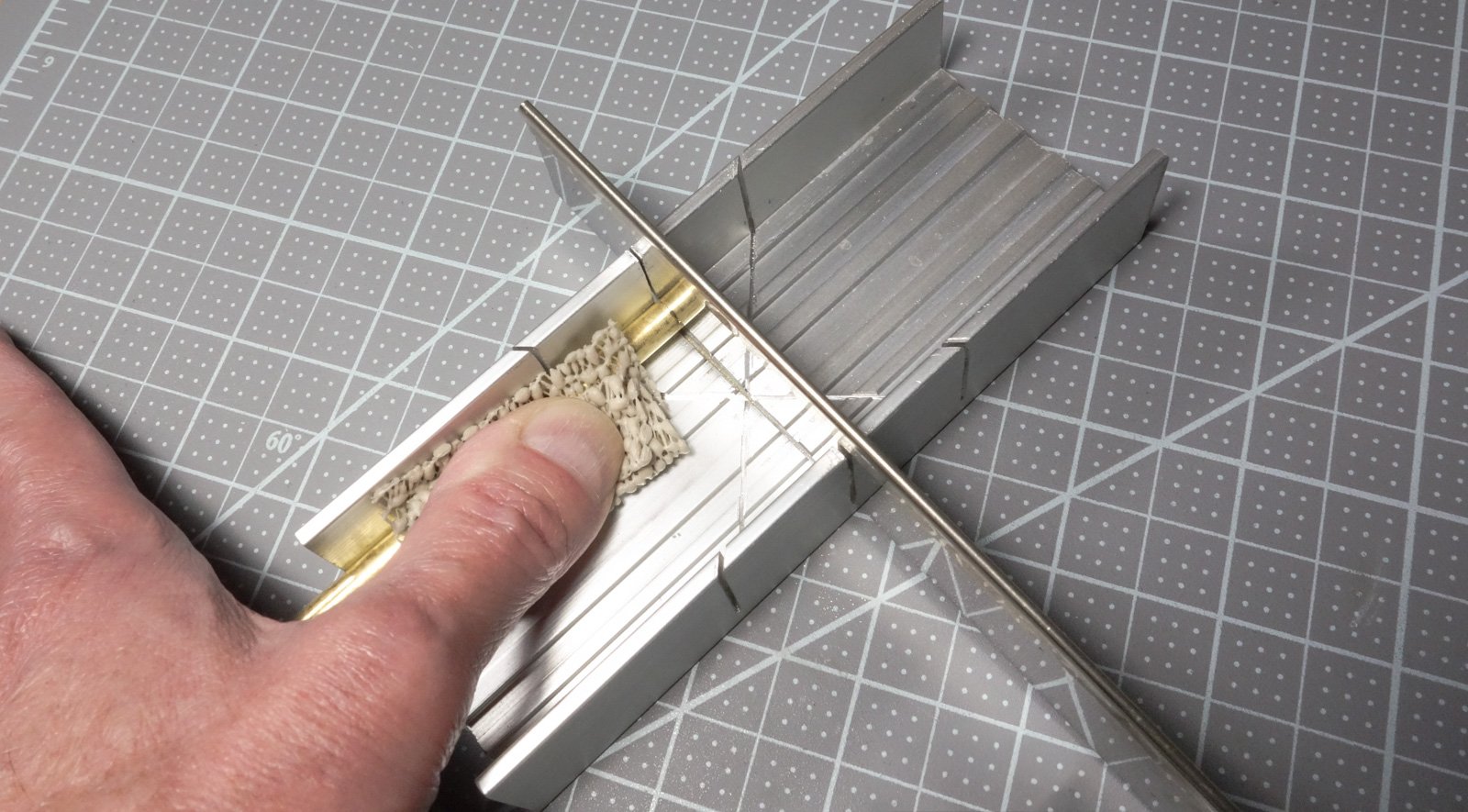
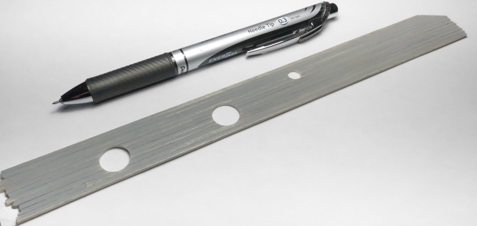
 Keith, Druxey, Paul, Glen, Marc, Bill, John and Tom - thank you very much for your comments and kind words - so appreciated. And of course, thanks to all for the "likes". It's as low-tech as it gets, Bill. X-acto razor saw and miter box. I've been using this same blade for a long time, and I'm actually amazed it's still cuts. I think it's 42 tpi, but not sure. The piece of no-slip shelf lining makes a big difference in keeping the tube from rolling. Hey Tom. I use a lot of purchased wood strips, and I think I spent around $45 on wood for this model. It's all "O" scale (1:43) stuff which is a little larger than 1:48, but that works out OK as I end up shaving, slicing, filing or sanding almost everything before using it anyway. I modify probably 65% of it to get to the dimensions I need. And I'm close friends with my digital calipers. Gary
-
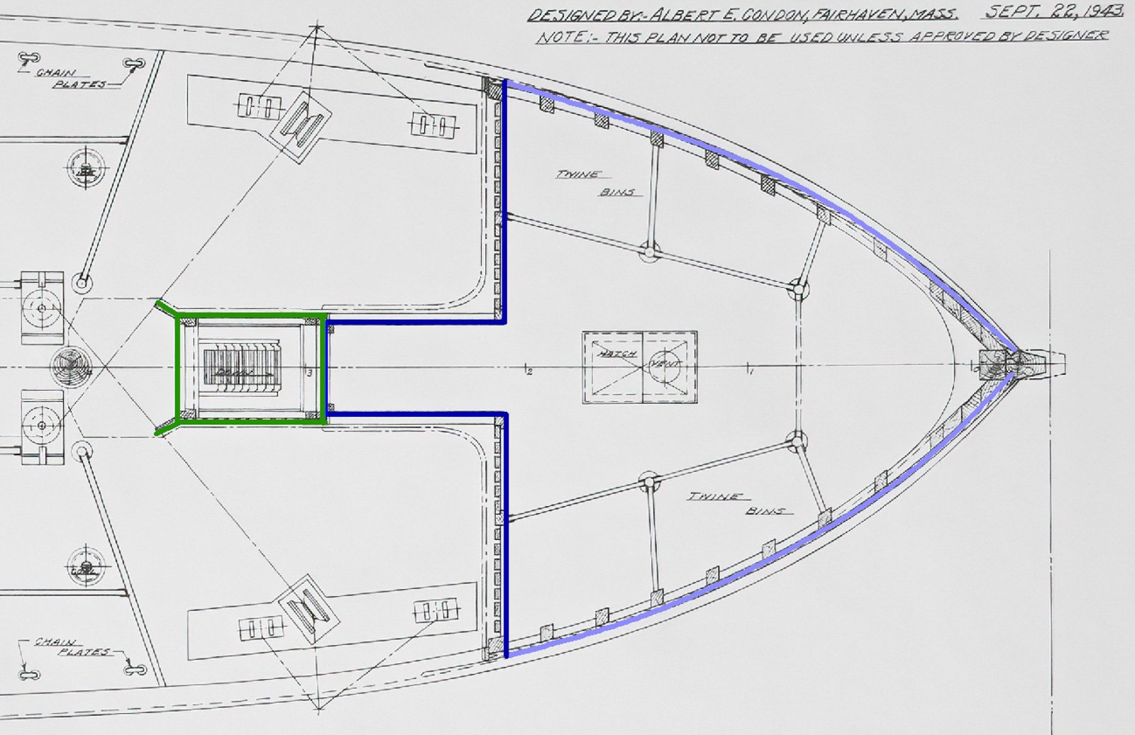
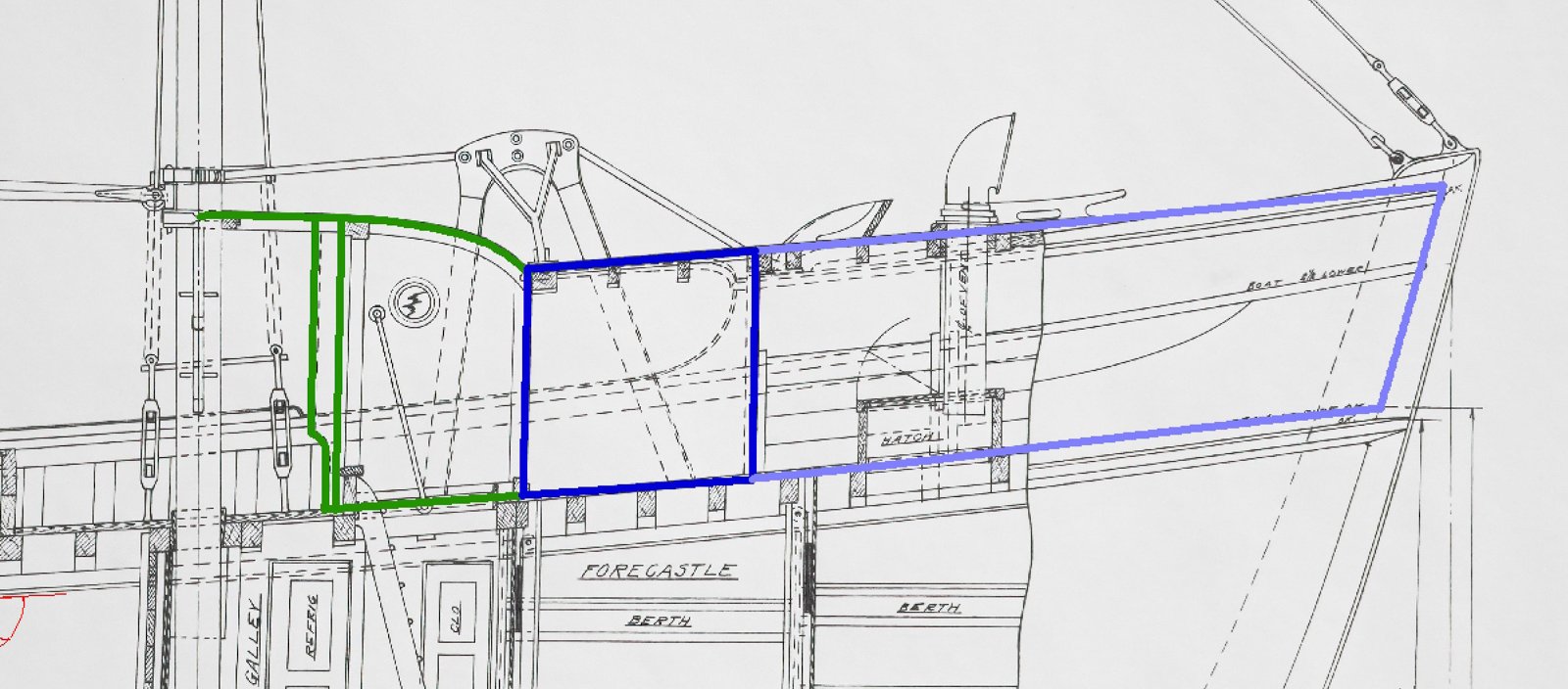
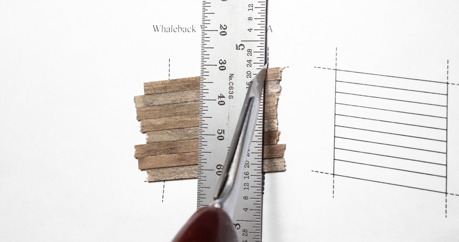
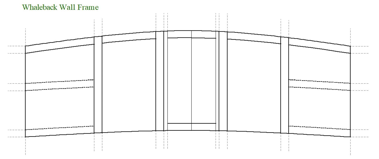
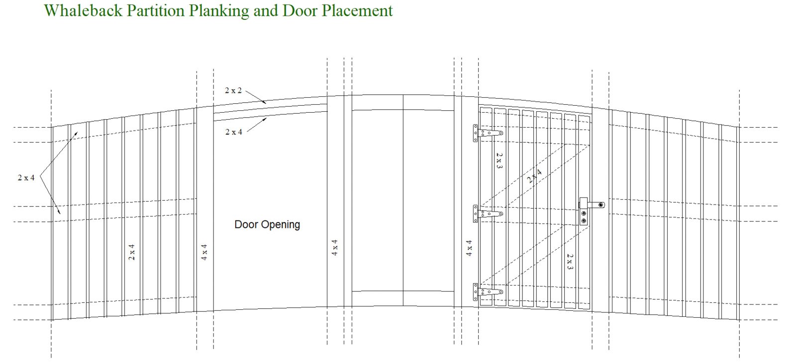
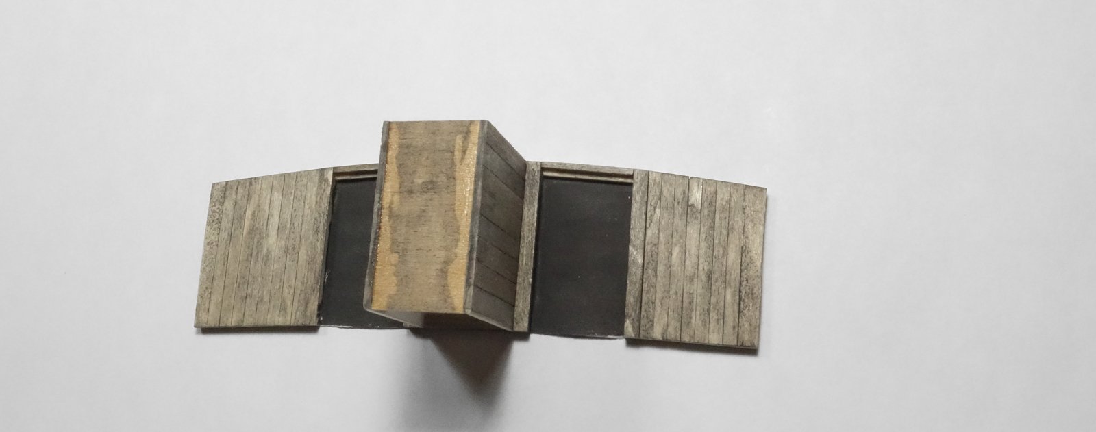
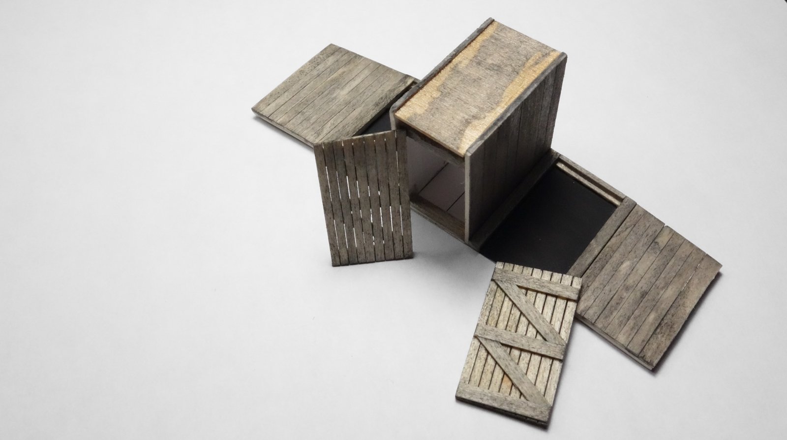
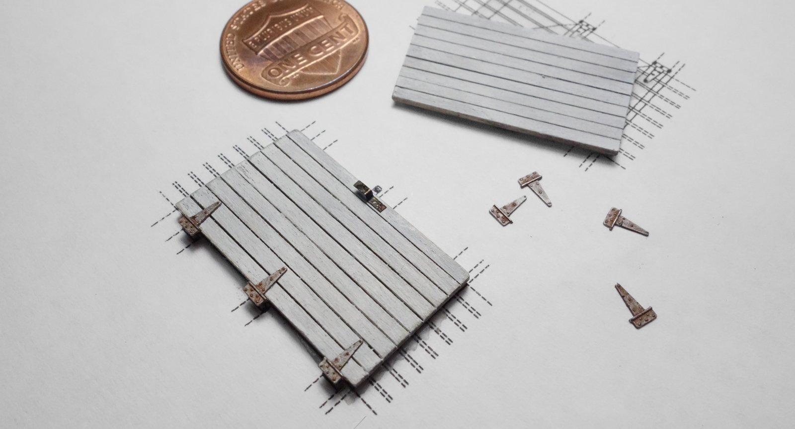
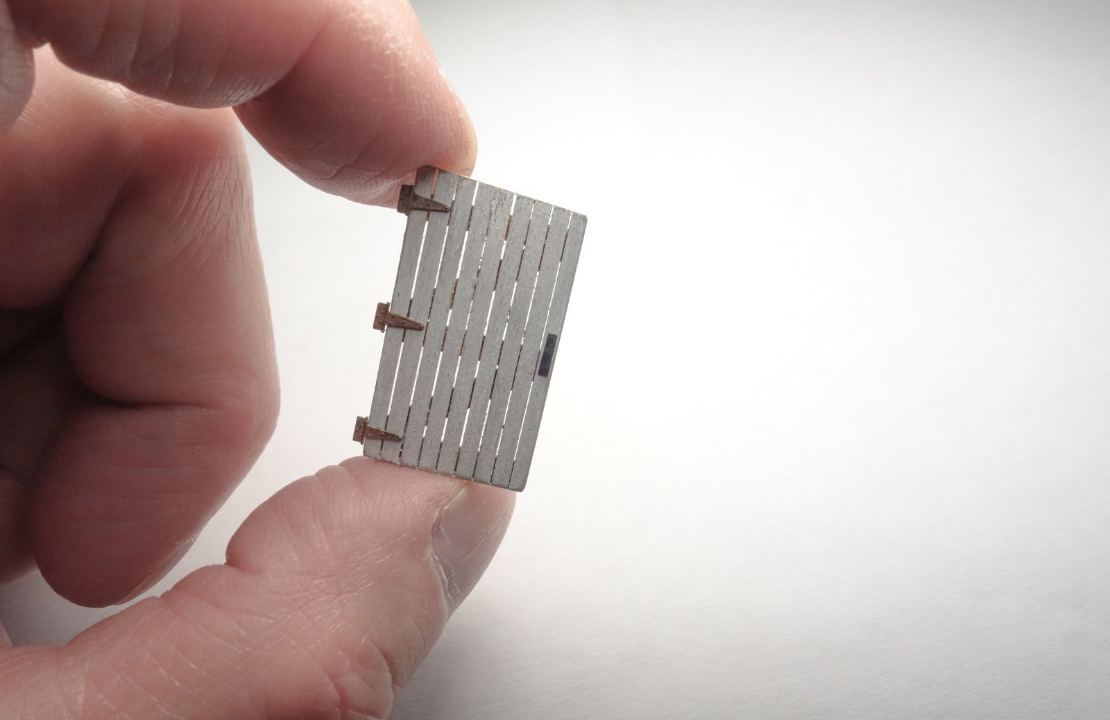
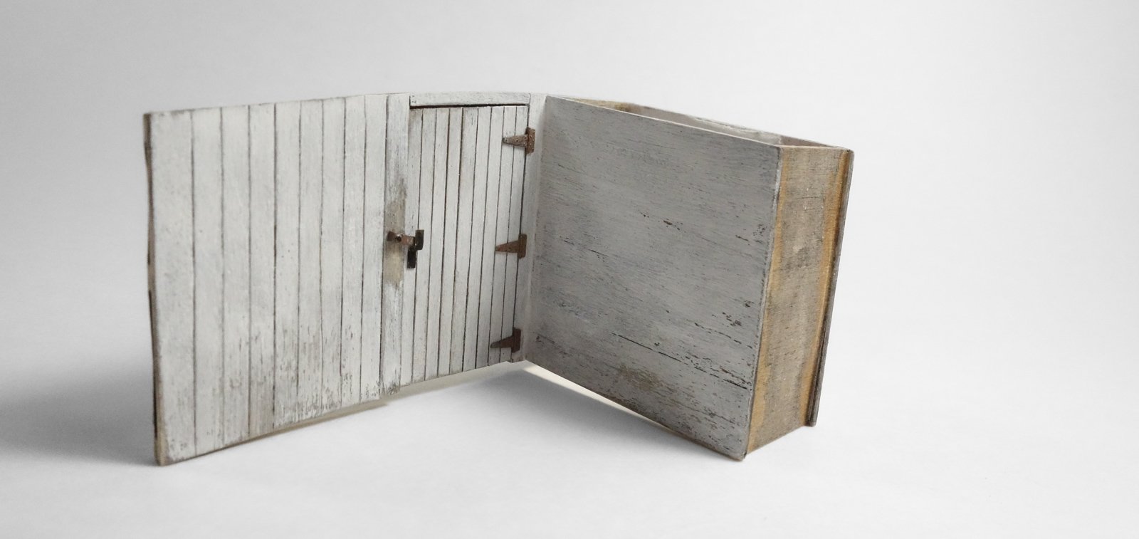
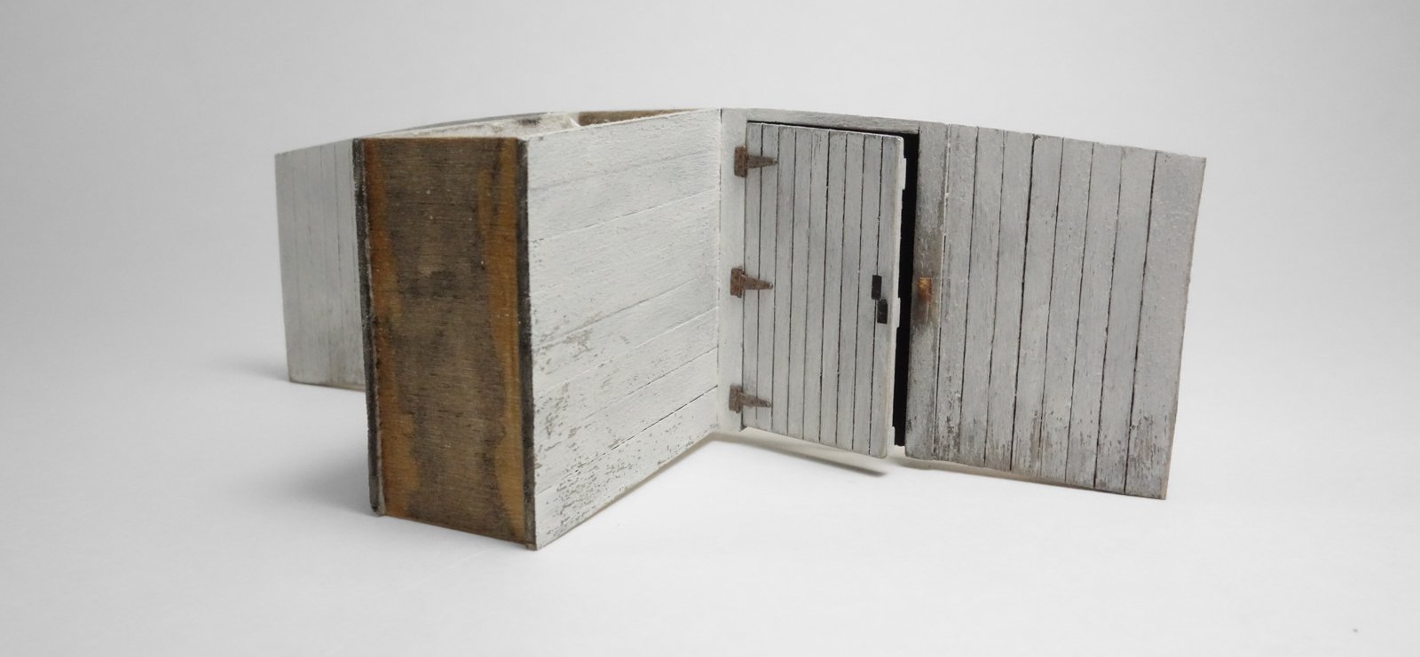
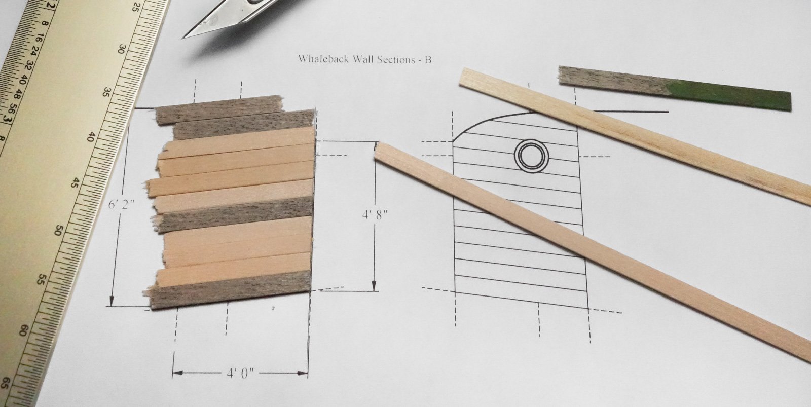
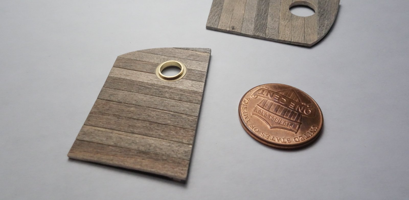
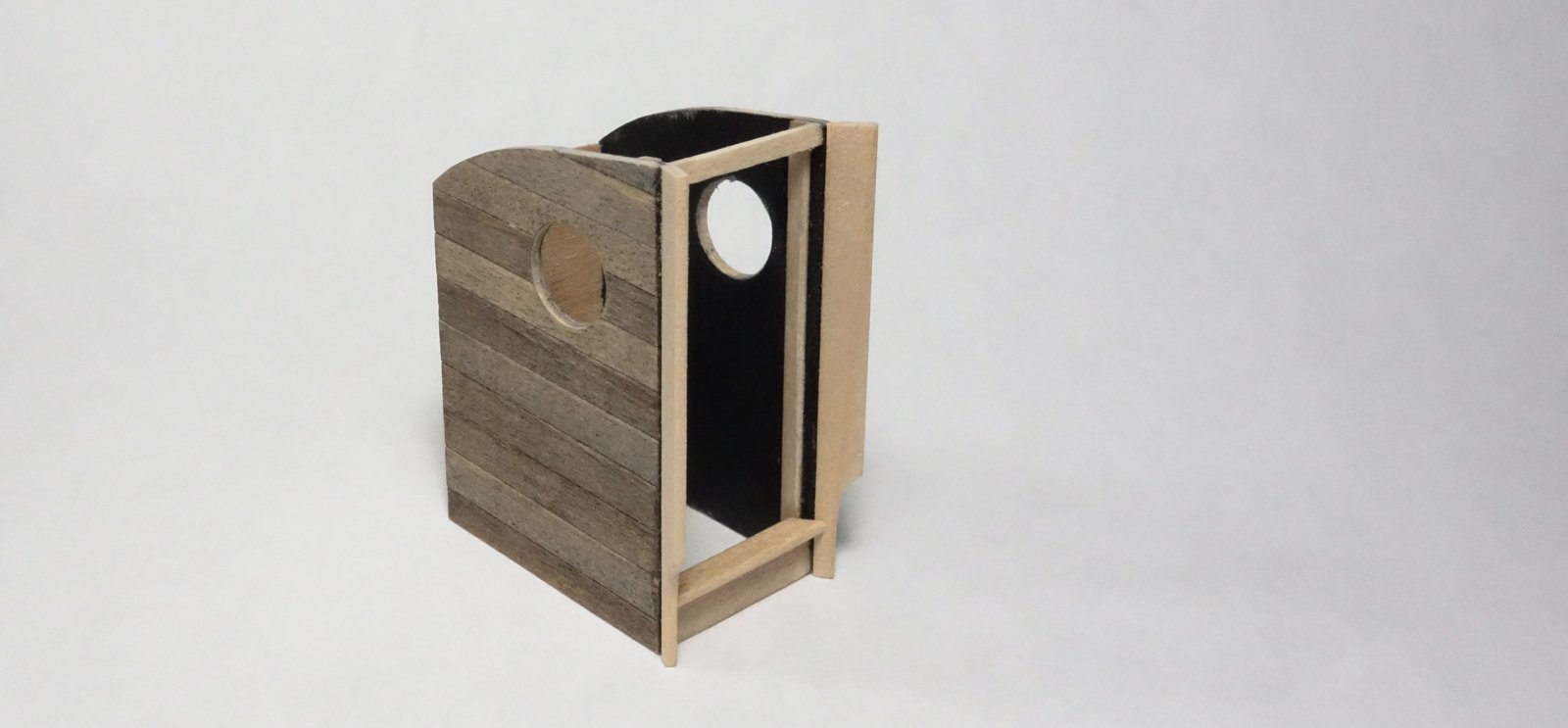
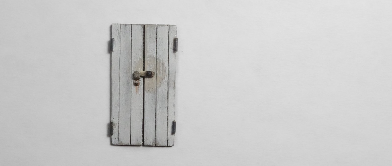
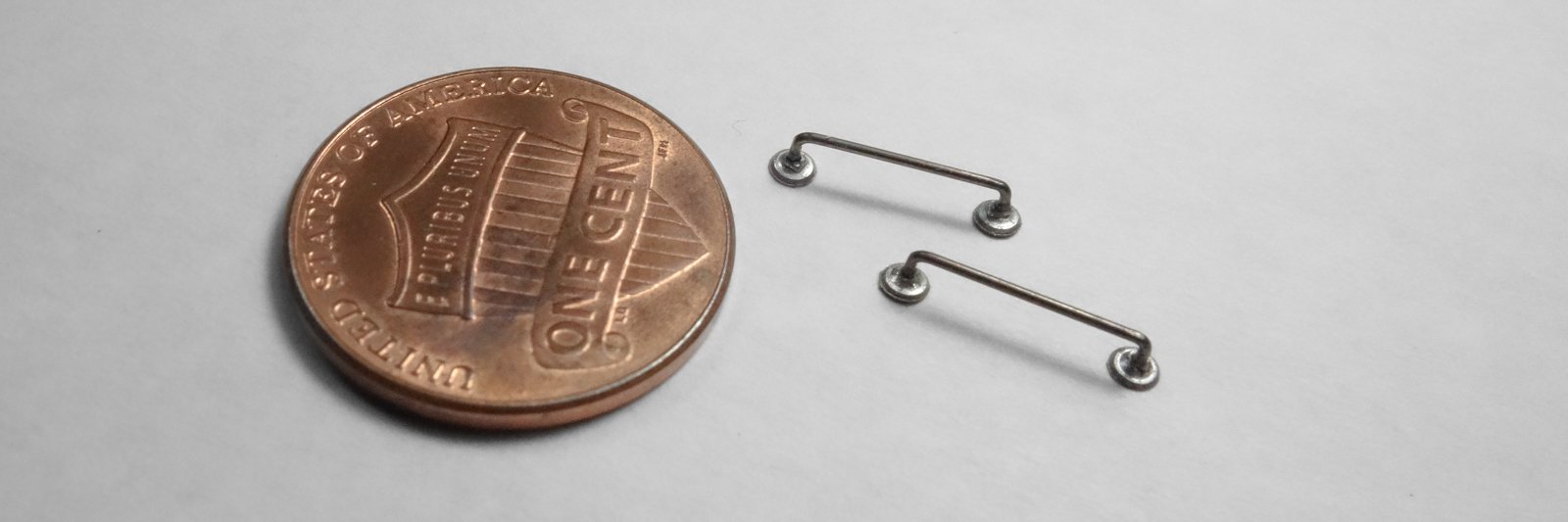
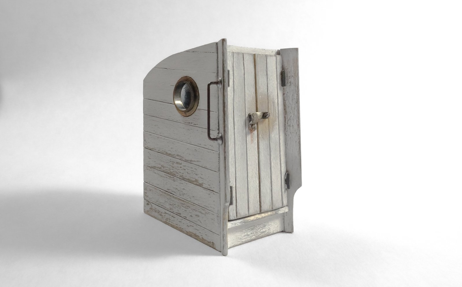
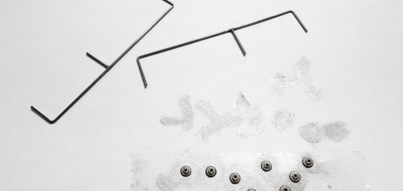
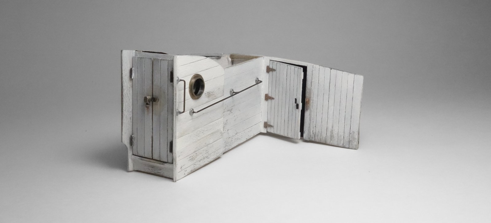
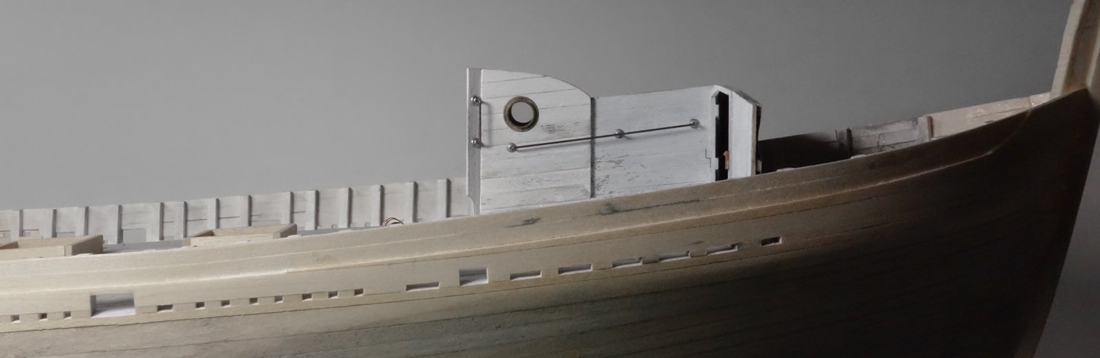
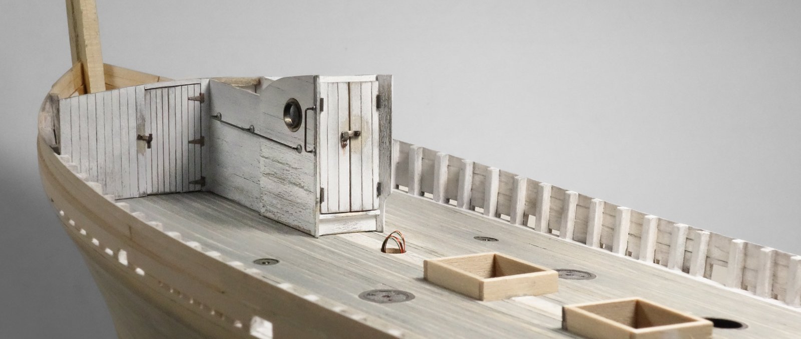
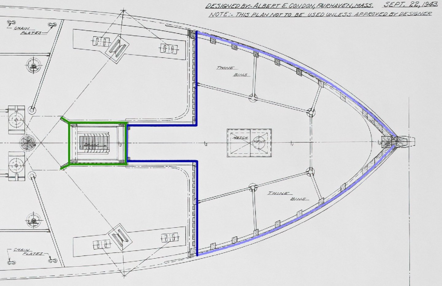
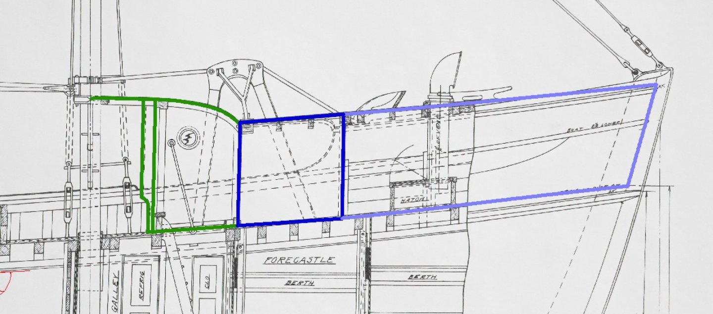
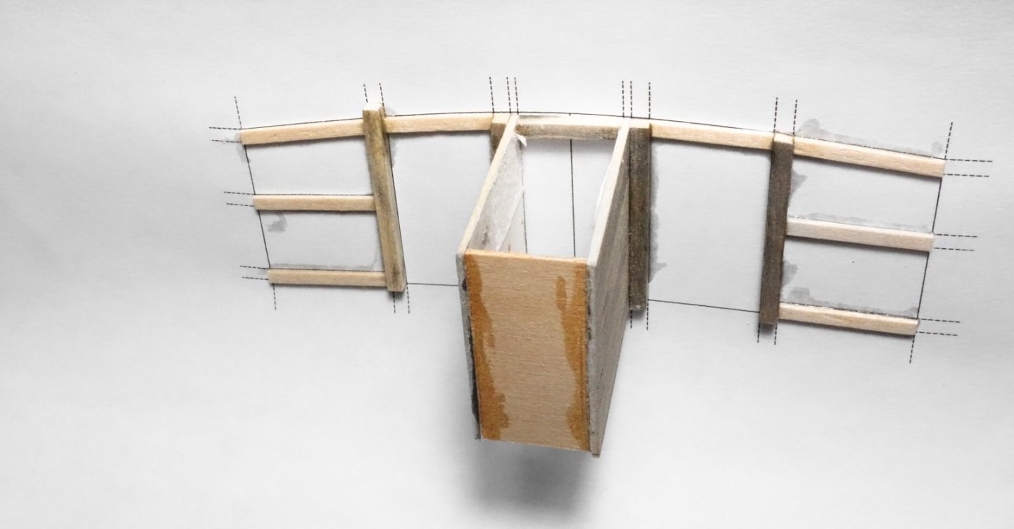
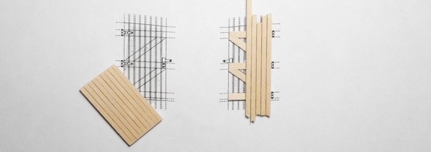
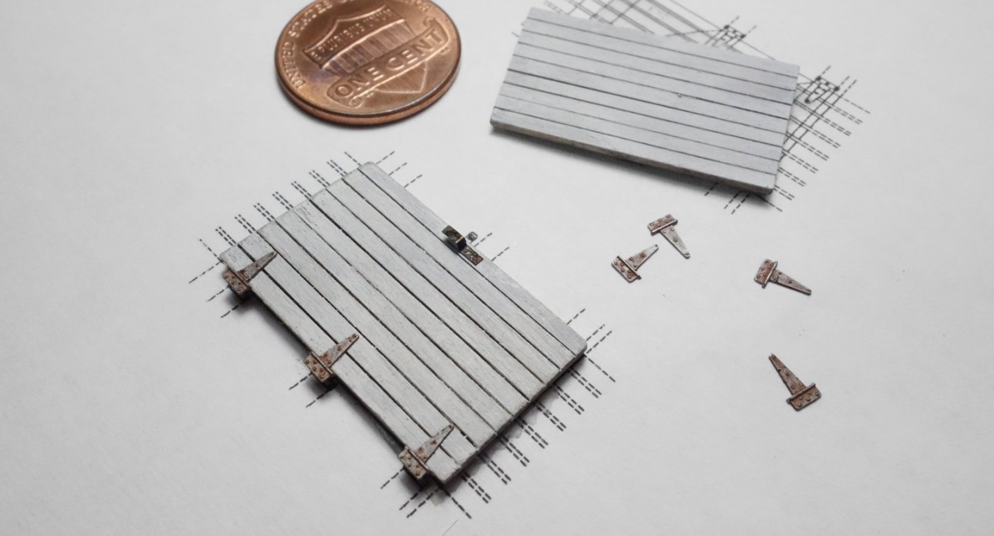
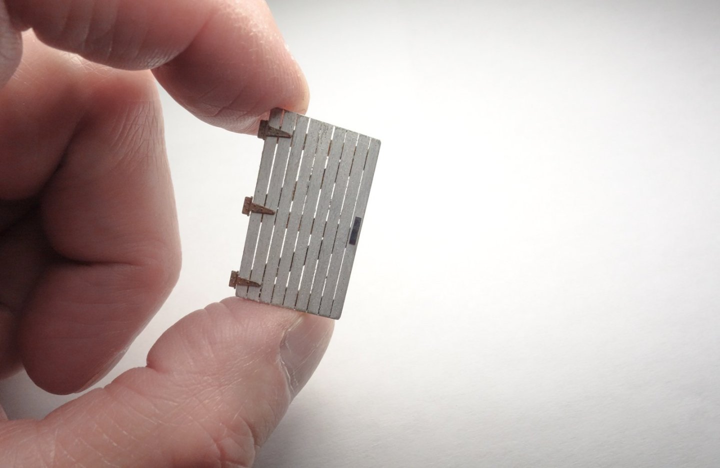
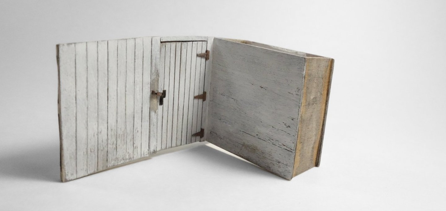
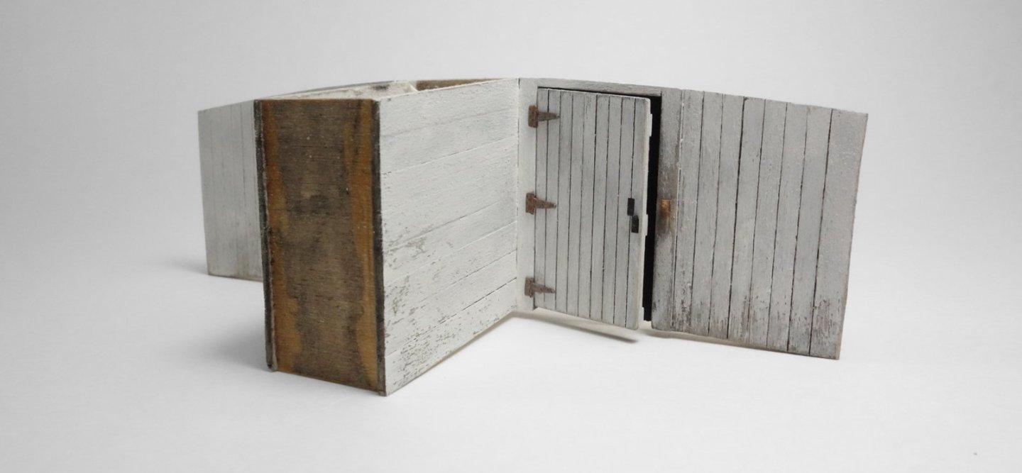
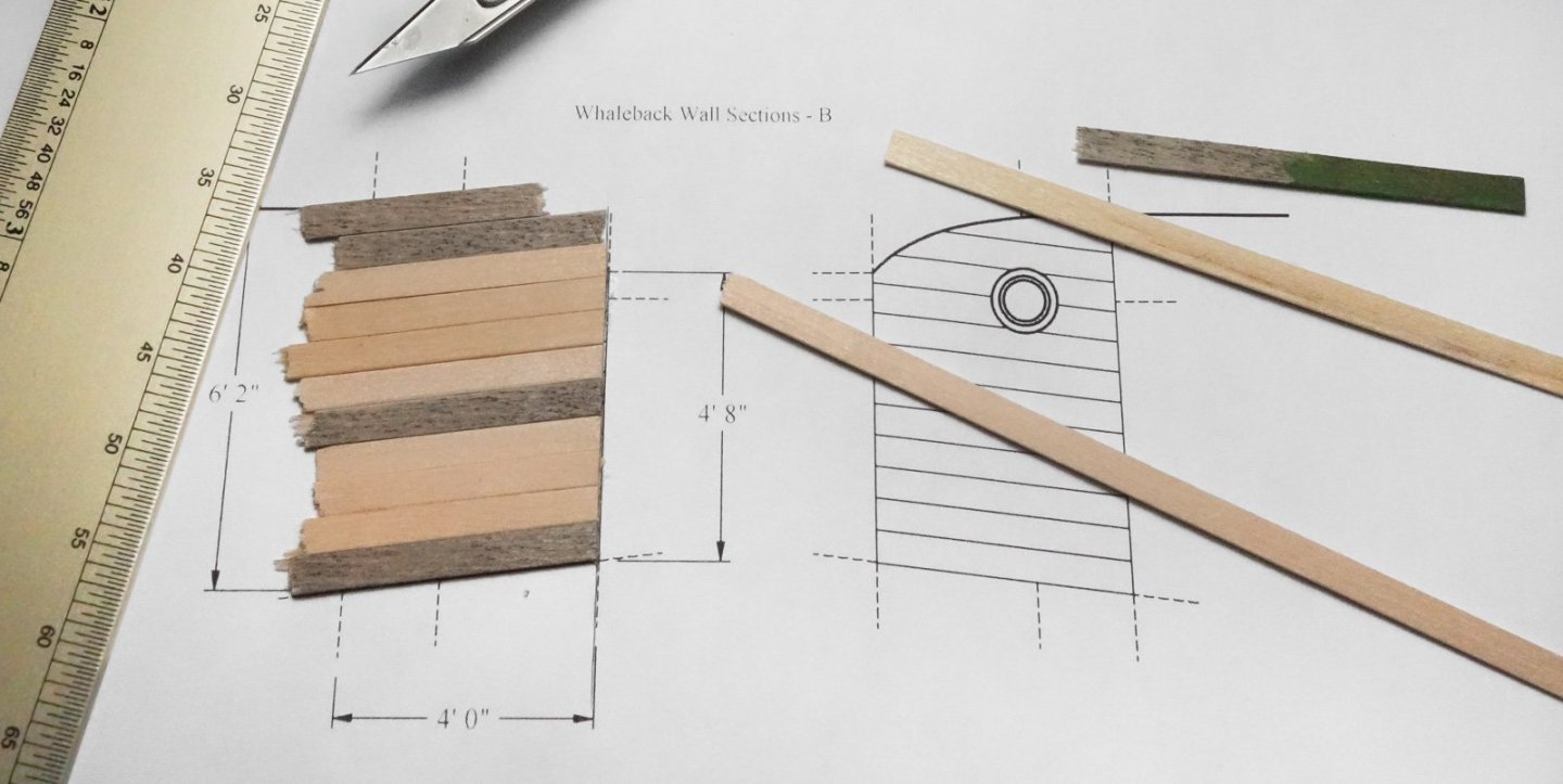
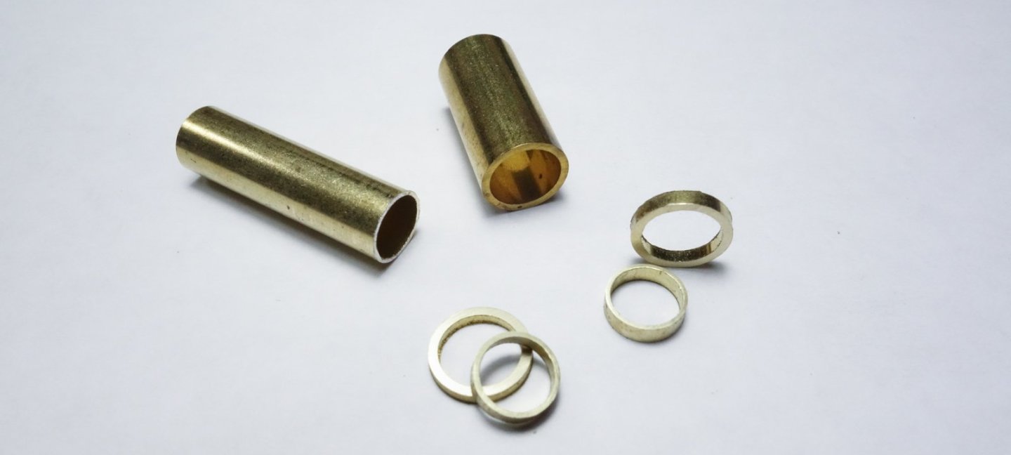
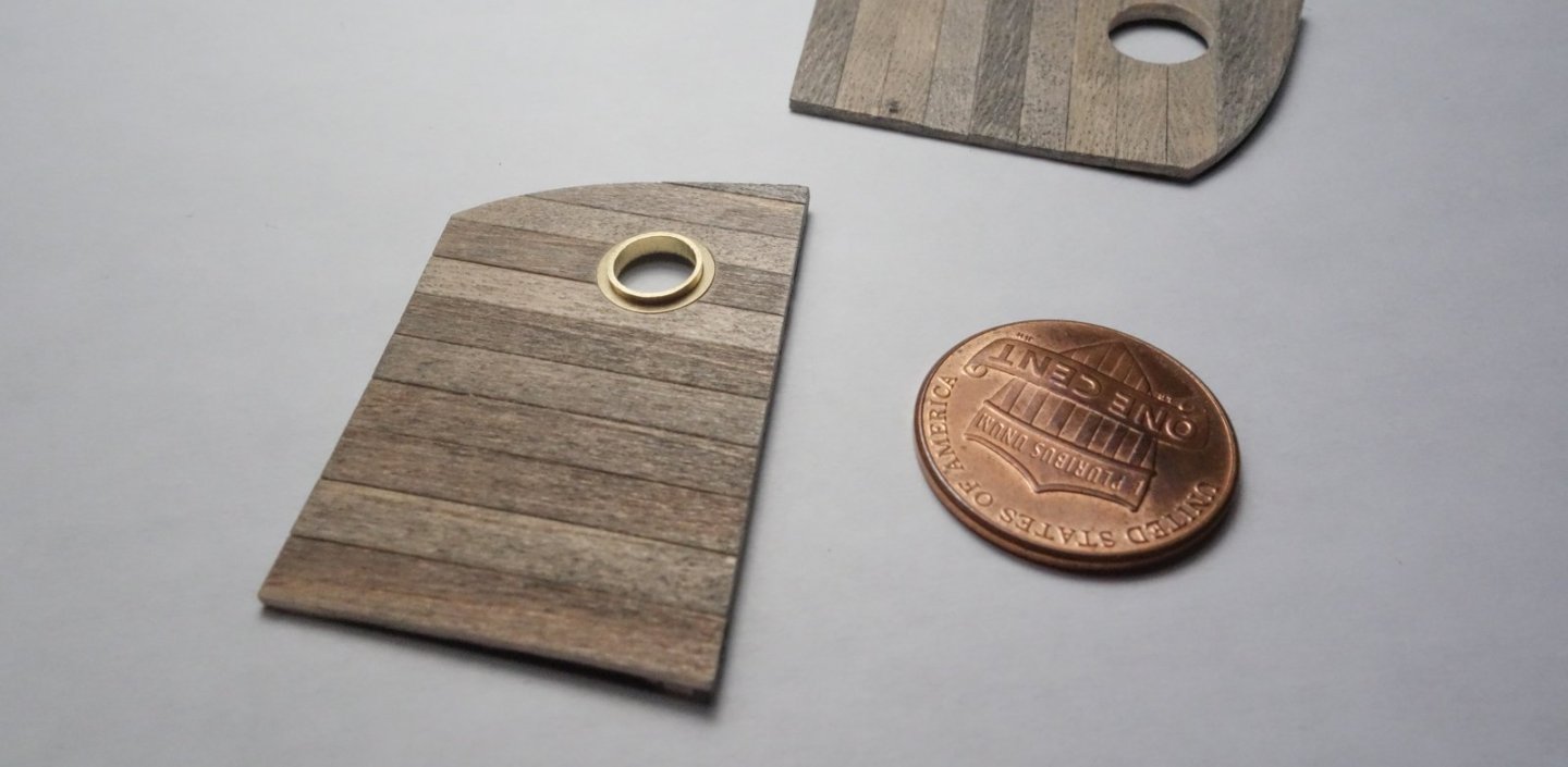
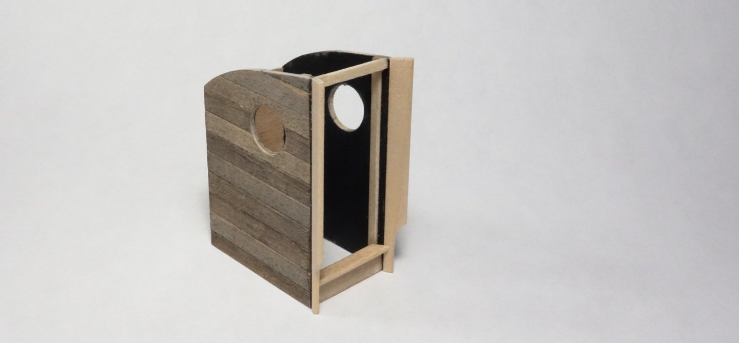
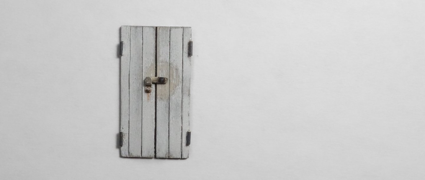
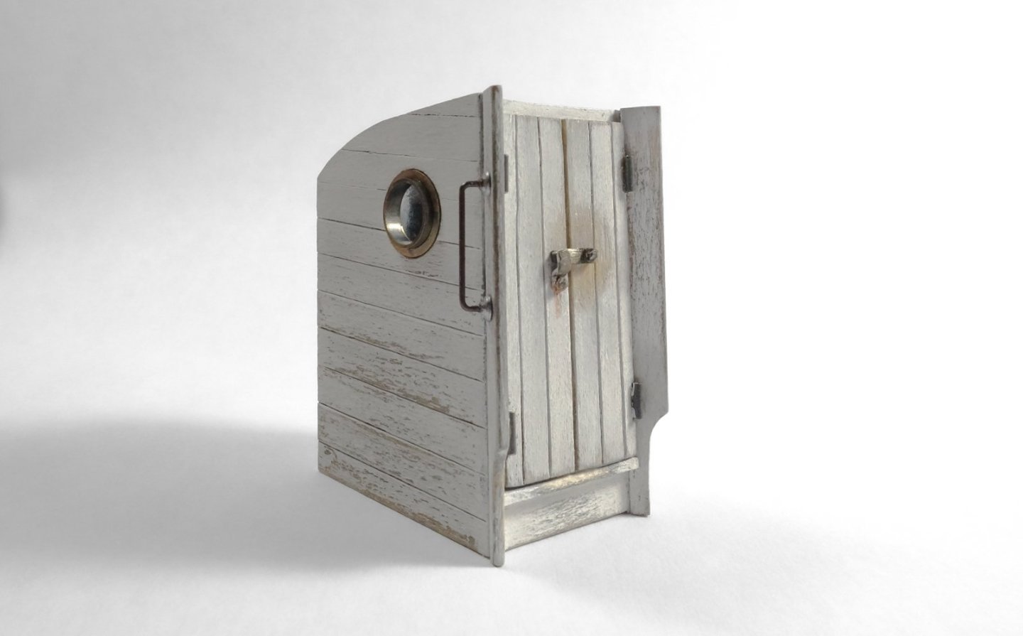
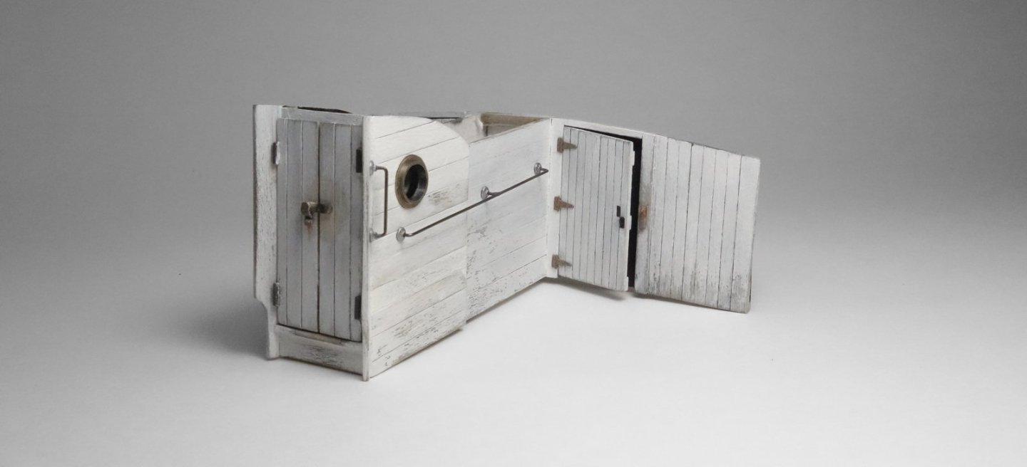
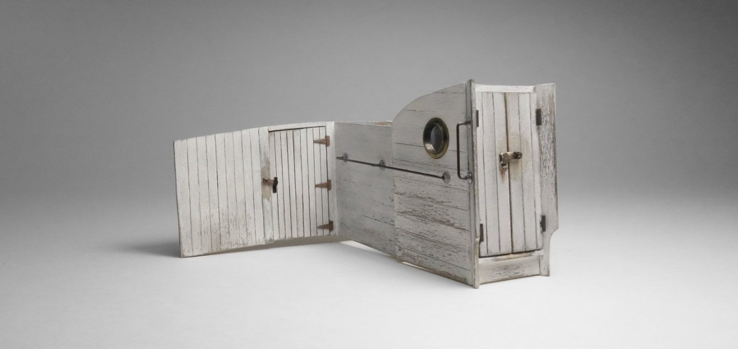
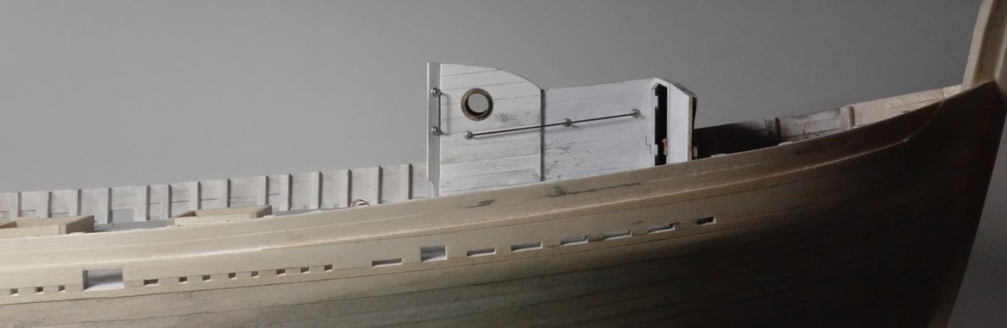
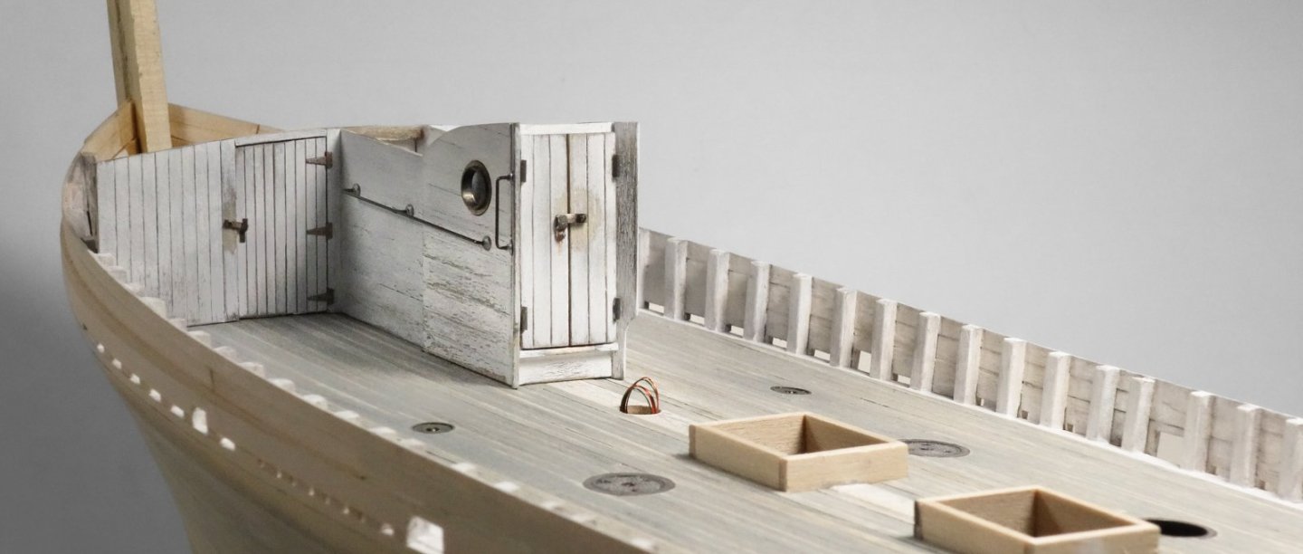
Greetings Fellow Modelers. Thanks for the "thumbs up" and for stopping by. Hey Keith - no I don't turn them on very often at all. And actually, once I finish a model, I rarely even look it again except in passing. The fun was in the building, and I don't need to see things I wish I'd done differently. A few years ago, I started building small shadowbox scenes where lighting is important, and I've carried some of that over into fishing boats. It's pretty quick and easy to do so - why not. And I have noticed that casual model viewers seem to really get a kick out of it. Whaleback -part 1 In the context of an Eastern-rig dragger, the whaleback is an elevated bow structure that provides a measure of protection for the crew when working the open deck in heavy weather. The structure also adds storage space on the main deck for spare gear such as netting, chafing and roller gear, twine, cable, etc. A whaleback was typically only built on larger draggers and sometimes mid-sized boats like the Pelican. In the drawing below, the perimeter of the whaleback is high-lighted in blue. The aft wall sections (darker blue) are what I'll be modeling in this post along with the companionway doghouse outlined in green. I began with the small walled in section that extends aft of the main storage space and butts up to the backside of the companionway doghouse. There is no passage between these two structures. Entry into this space is through the main storage area of the whaleback only. It is a rather curious little space where the crew stored the deck chairs and chilled bottles of chardonnay – or not. Joking aside, in subsequent years this spot held the fuel tank for the galley below, presumably kerosene. I'm a bit surprised that this boat in the mid 1940s was still using coal for this purpose. Anyway, I drew up the wall sections and glued pre-stained siding to the template and cut them free. Like all things in boat model building, nothing is square, level or straight. This structure leans toward the bow mirroring the sheer. The main wall framing is drawn up with its lower edge conforming to the crown of the deck. The top of the wall will be a landing spot for the roof and is more severely domed. The wall is constructed and the previous assembly glued to it. The partition needs planking. And the walls need doors. These doorways are short and potential head bangers, about 4’4” (132cm). The doors (and everything else) were brush painted with Tamiya flat white acrylic with a touch of red and yellow to warm it just a bit. The hinges came out of my junk box without packaging but are undoubtedly from Grandt Line. They're painted with Testors “flat steel” enamel and rust colored pigment powder was daubed on while still wet. The latch bracket is blackened .01” (.25mm) brass. Painted and glued together. Someone left the starboard door unlatched. The companionway doghouse is drawn and assembled using up wood strip scraps. The structure has two small portholes with 8” dia. openings made from slide fit brass tubing slices. The outer tubing has a thicker sidewall and pretends to be a mounting flange. The holes in the siding that accept the lights were drilled through first and expanded with a tapered file, then test fit. The doorway threshold stands 12” (30.5cm) above deck to keep storm water from cascading down the companionway. The structure has 12” wide vertical boards attached to the doorway corners at an angle of about 45 degrees. Their purpose is unknown to me, but because it’s a two-piece center opening door, I suspect they act as stops and keep the hinges from being torn off in windy conditions. Also, they are tapered at the bottom to reduce trip hazard. Speaking of trip hazard, the wire rope cables leading to the forward gallows frames cross inches from these boards about ten inches above the deck (see drawing at top of post.) The structure gets paint, the portholes are glued in, and a small piece of microscope cover slip glass is attached to the backside for glazing. The glass is 0.13mm thick. The brass portholes were only blackened long enough to take the shine off, and the outer ring was left a little proud to represent a surface mounted flange. The door is constructed. It is 26” (66cm) wide by 58” (147cm) tall. Grab irons are made from .02” (.5mm) phosphor bronze wire treated with Jax Flemish Grey. The pipe flange wall mounts are injection molded washer/nut sets from TichyTrain. I filed most of the nut off and drilled them out. Chrome enamel paint. The chipped and missing paint on the siding is achieved by applying cellophane tape and then ripping it off like an old bandage. I burnish the tape down with a fingernail in areas where I want more of the paint removed. By staining all the wood prior to painting, this process reveals wood that looks aged. Soldered railings. Again, phosphor bronze wire. This stuff won’t sag as easily as brass will. Placed on but not glued to the boat. After it is permanently attached, I’ll add base trim. Next comes the roof (or would that be deck?) and a bunch of other stuff. Thanks for looking. Be safe and stay well. Gary


-
Sweet looking hull, Keith - beautiful! Gary
-
Very nice, Paul - everything looks great! Gary
- 201 replies
-
- 5
-

-

-
- Oyster Sharpie
- first scratch build
- (and 1 more)
-
Good progress, Ken! Gary
-
Good to hear you had an enjoyable get-away, Glen. Nice progress on the Constitution! Gary
- 301 replies
-
- 3
-
-
-
- Constitution
- Bluejacket Shipcrafters
- (and 1 more)
-
Fascinating post on planking, Andy. Please feel free to "ramble" with abandon. Very interesting stuff! Gary
- 174 replies
-
- 5
-
-
- Vigilance
- Sailing Trawler
- (and 1 more)
-
Nice to see an update on your model, Bruce. She's looking great and I really like the detailed work at the rudder post. Gary
-
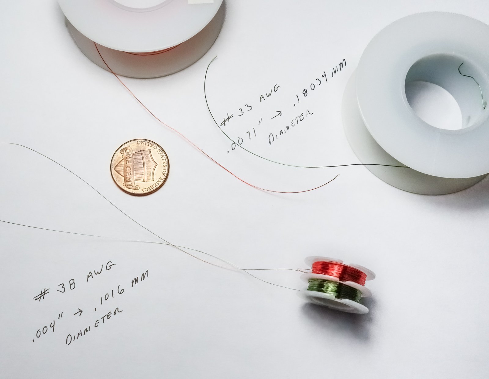
Thank you Druxey, Craig, Mike and Glen for your nice comments and to all for the "thumbs up". Yes, they are copper wires with a varnish insulation which is very tough and doesn't scrape off easily. I've had no problems with this type of insulation. The wire size question is more difficult to answer because there are many variables. I don't want to get into the weeds here, but the wire size needed depends on factors like the number of LEDs used, their size/output, circuit configuration, ambient temperature and even the length and type of insulation on the wire. Every wire/insulation combination has a safe maximum current rating, and every LED has a full voltage current draw, so it's a matter of math to find a proper match for the configuration of LEDs used. For a single small SMD like the #805 I'm using in the fish hold I use #38 awg. One LED only. For a few small LEDs I use #33 wire. But if you're considering adding model lighting, may I suggest saving yourself the guesswork and hassle of soldering your own and simply purchase prewired LEDs. Evan Designs, (who is one of this forum's sponsors) has a great selection of prewired power matching LEDs and other items (dimmers, flashers, remote control, etc.) to fix you up with whatever you need. There are many sellers of prewired LEDs on eBay also, but they don't come with the current limiting resistors you may need to match your power source. Not trying to discourage you, Mike, just pointing out an easier path. https://evandesigns.com Here's another good source of information and products for lighting models. https://ngineering.com/index.htm Thanks to all for stopping by. Gary

-
Nice solution for creating the traveler car, Paul. Ha, funny - but they look good to me even at a standstill and a long stare. Gary
- 201 replies
-
- 5
-
-
-
- Oyster Sharpie
- first scratch build
- (and 1 more)
-
Looking very nice, John! Gary
-
Just read through your log, Craig and enjoying your process and craftsmanship! The model is looking great and your informational and clearly expressed narration is appreciated. Gary
-
Wonderful work as always, Valeriy! Those gears are great, and the warping heads are jewelry. Gary
-
Looking great, Roel. Extraordinary detail - fantastic! Gary
-
Andy, Paul, Keith, Richard, John, Håkan, Jerome and Marc - thank you for your thoughtful comments! And thanks to all for the "thumbs up". Just a short update. The starboard side deck plate section has been attached to the boat and the planking has been extended to the covering boards. The plans didn't show that the planks were nibbed into the side of the covering boards, so I didn't. The deck still needs traffic wear patterns and some weathering, but that will be a bit later. And then a quick test to see if the fish hold lighting peaks out between the planks. It doesn't, which is good because I had no plan “B” beyond reciting a string of expletives to myself. Before I begin the aft deck, I'm going to build the bow whaleback structure next, simply for a change of pace. Thanks for looking. Gary
-
Been reading through your log and I'm enjoying this build very much. Interesting subject and stories, Phil. And thank you for your service. Will be watching for updates. Gary
- 484 replies
-
- 3
-
-
- minesweeper
- Cape
- (and 1 more)
-
Good to hear from you Håkan, and I'm looking forward to seeing updates on Atlantica in due time. Gary
-
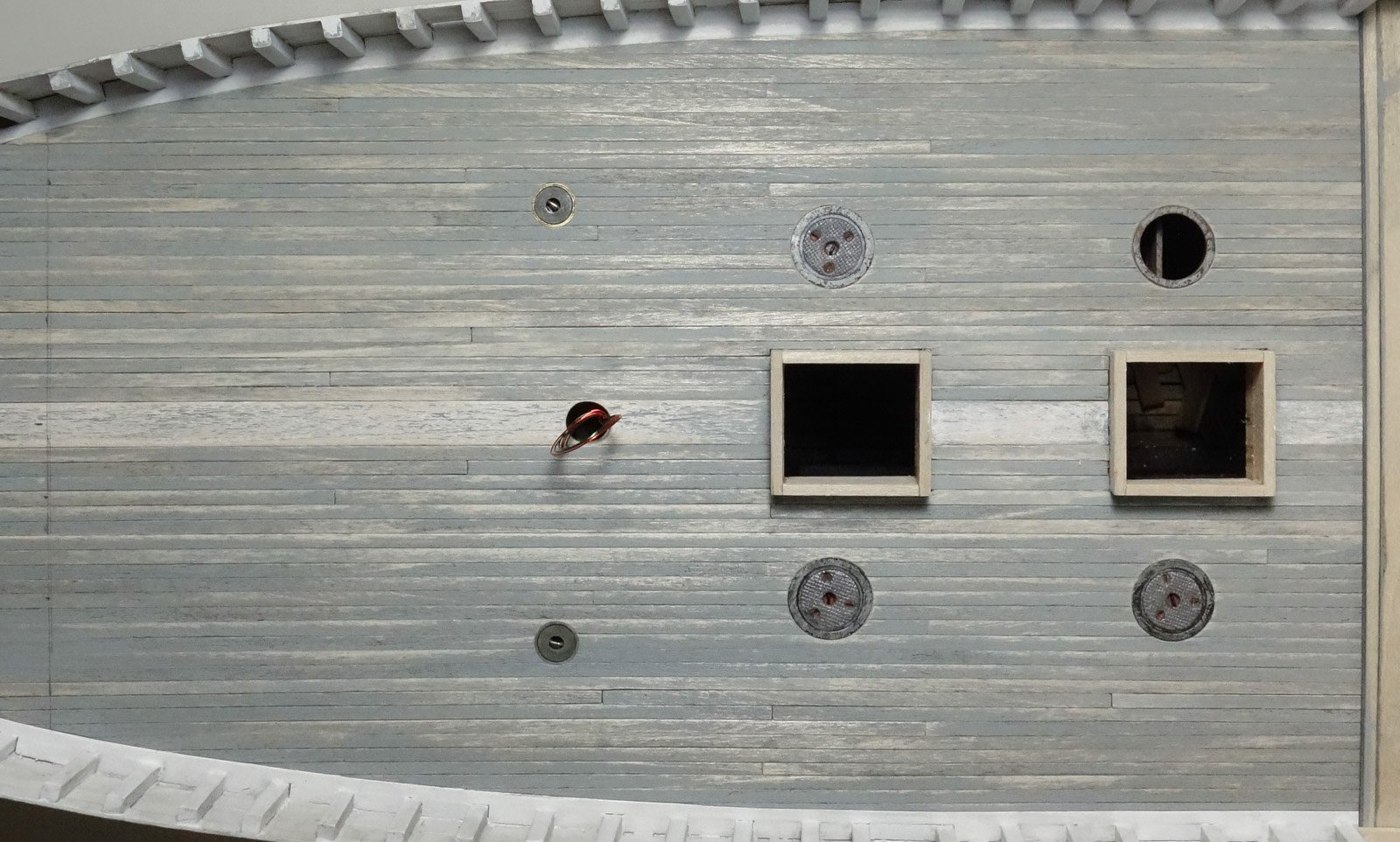
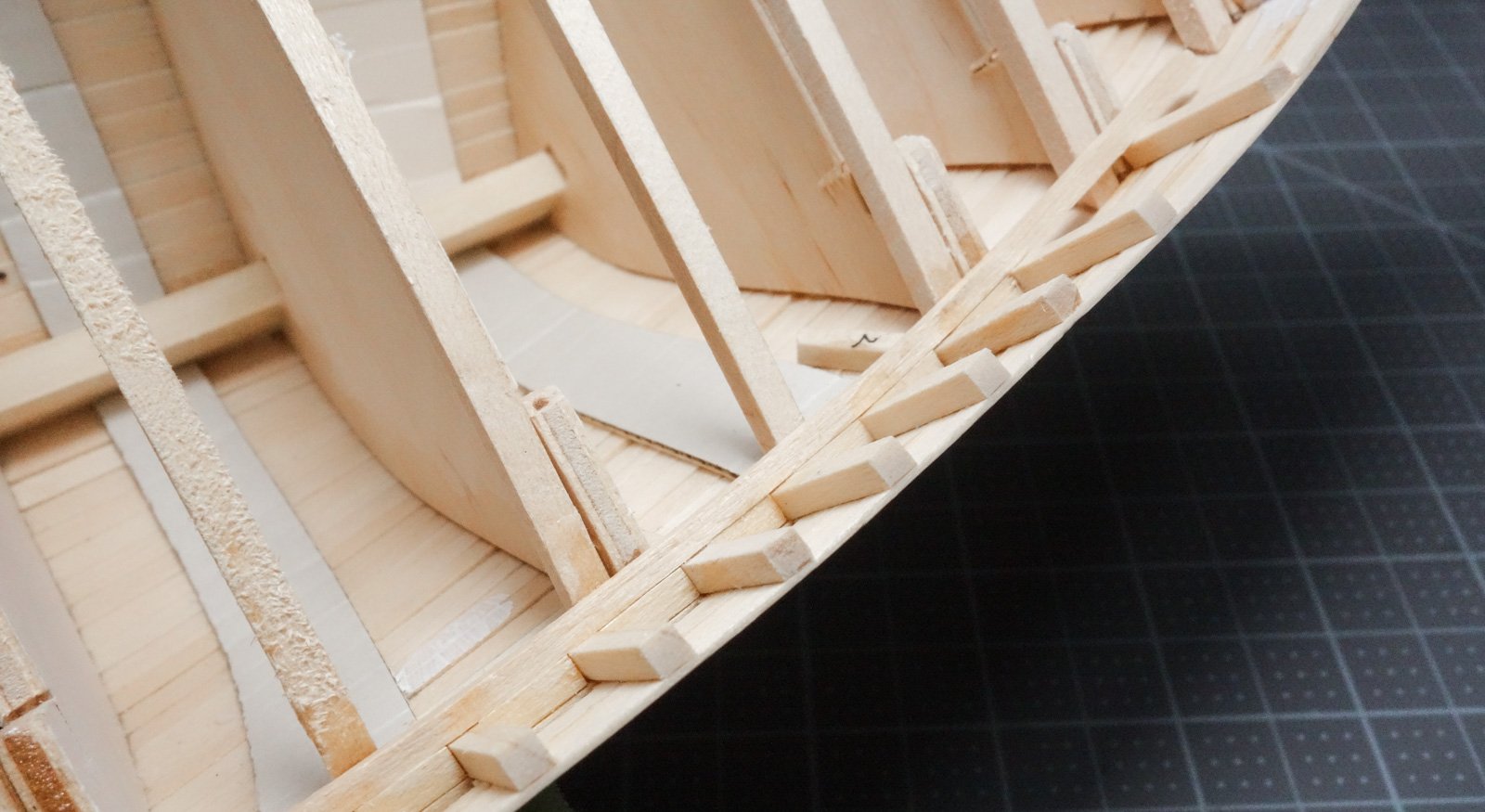
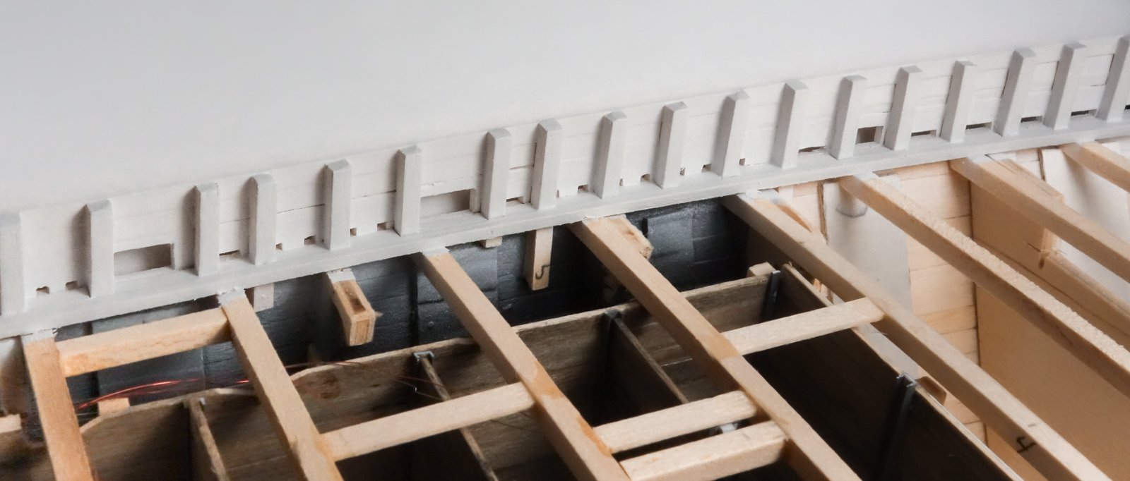
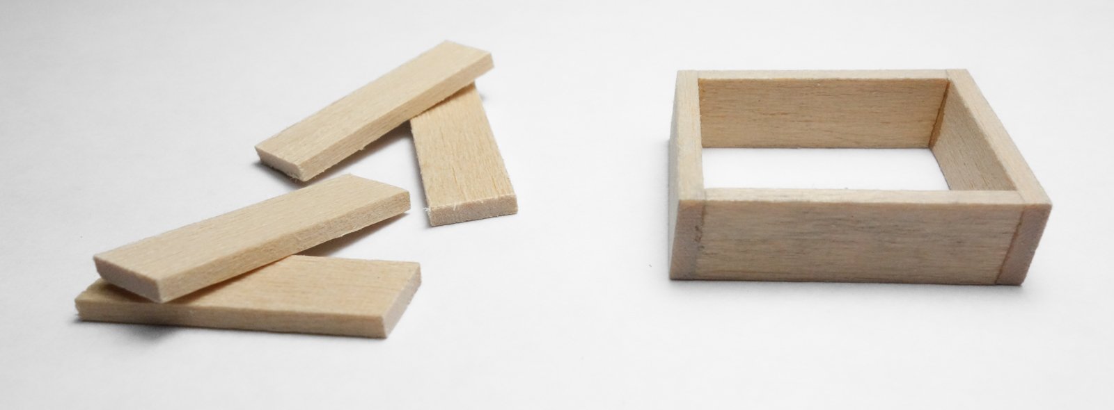
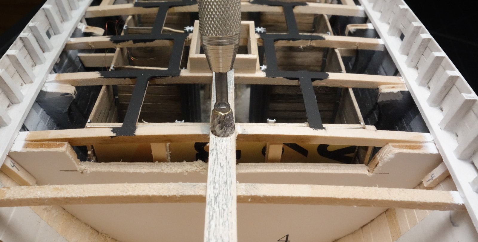
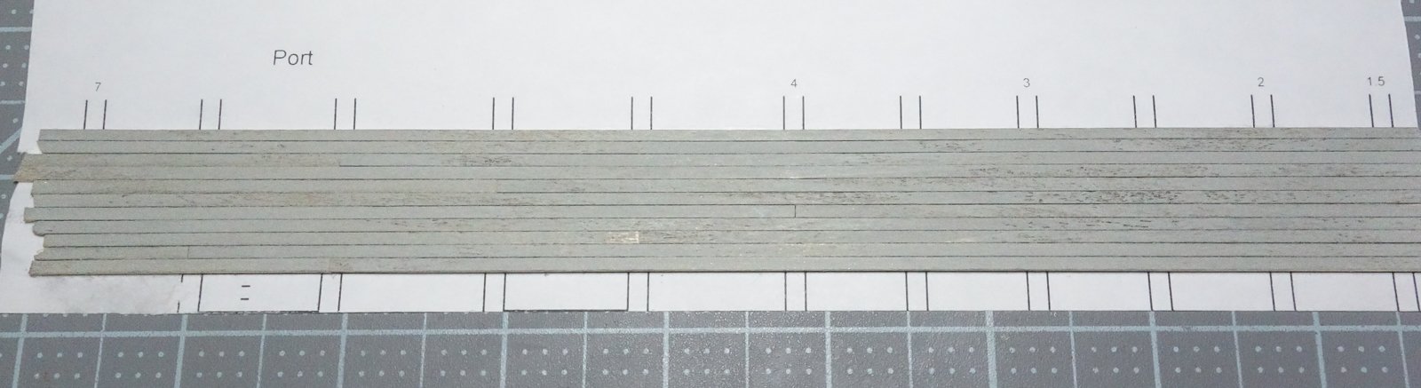
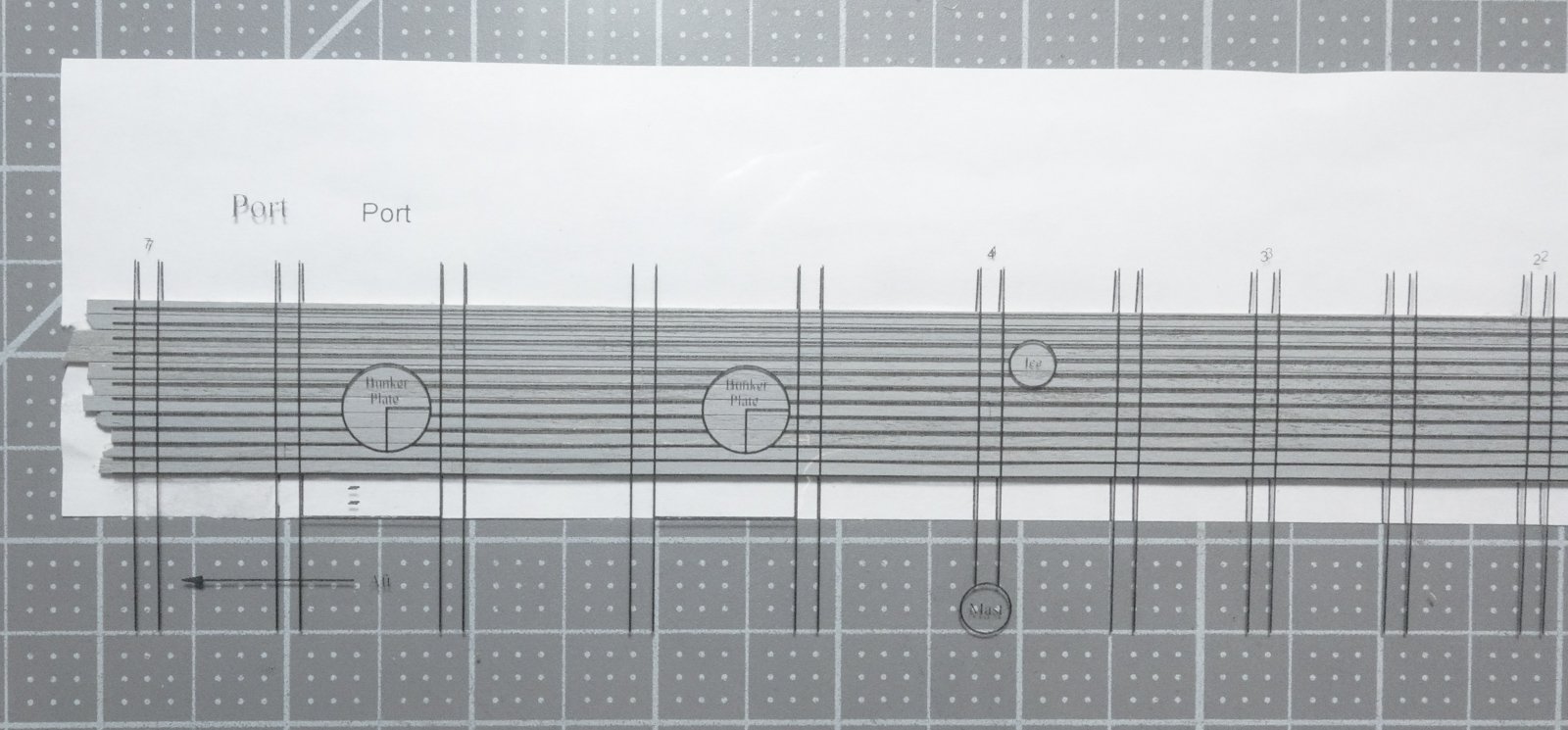
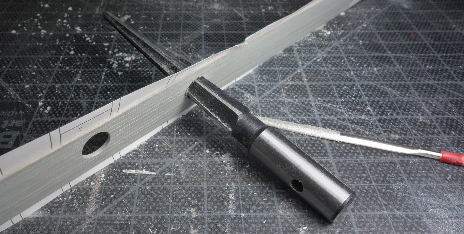
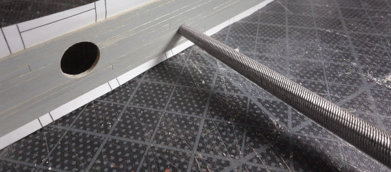
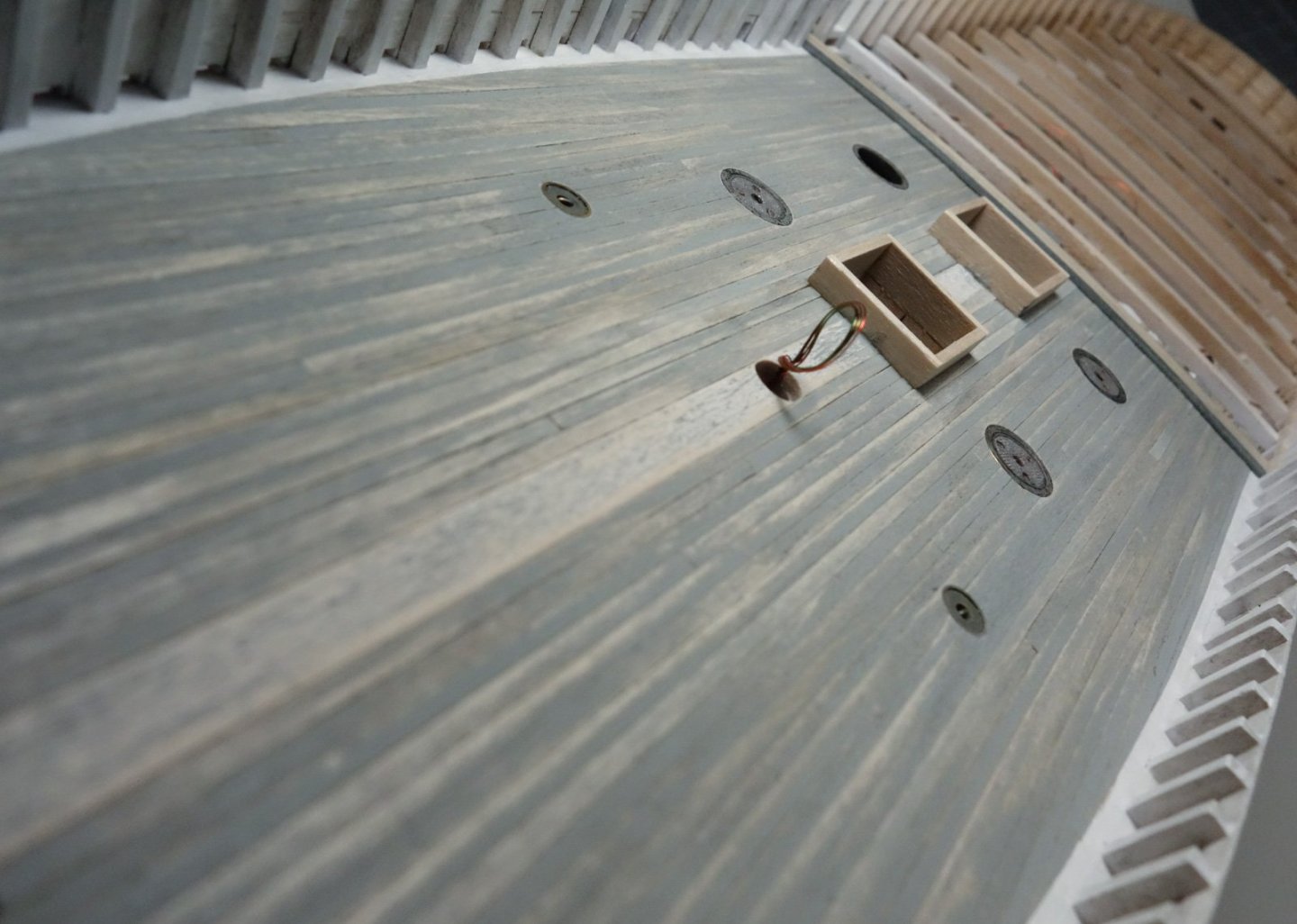
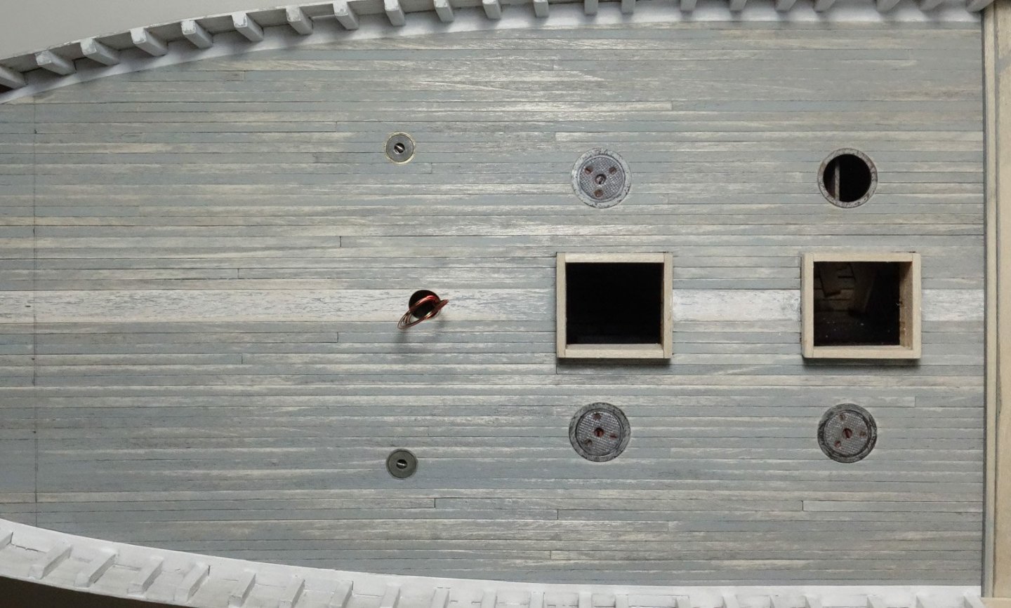
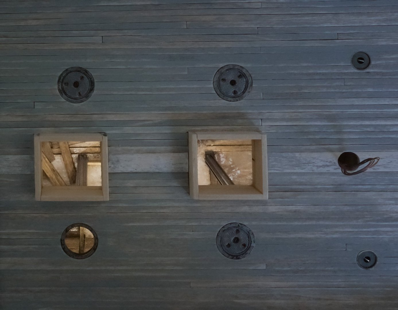
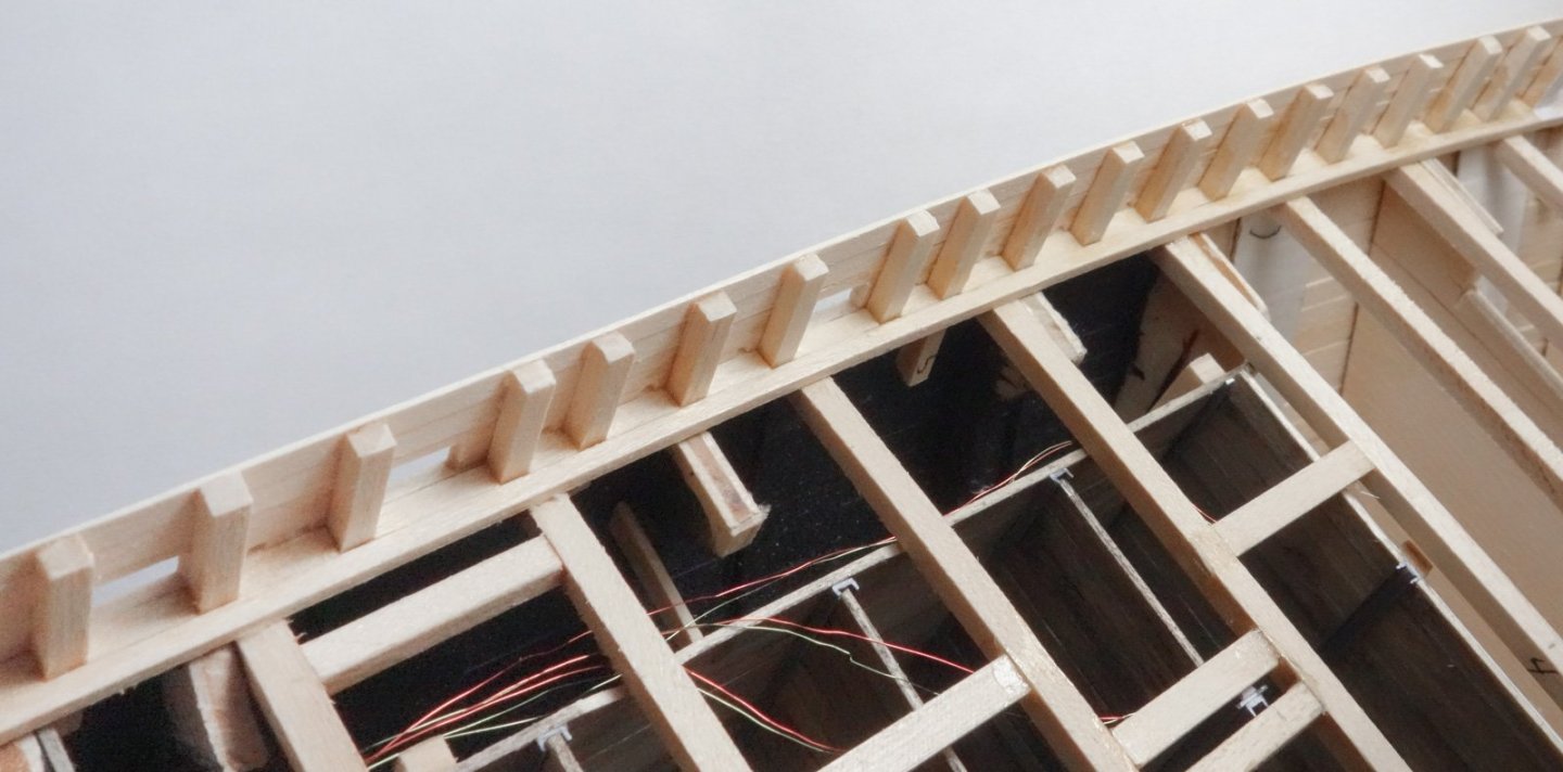
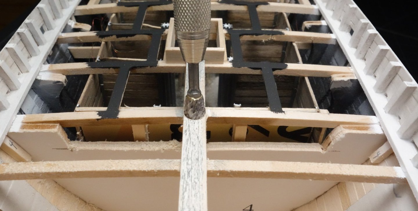
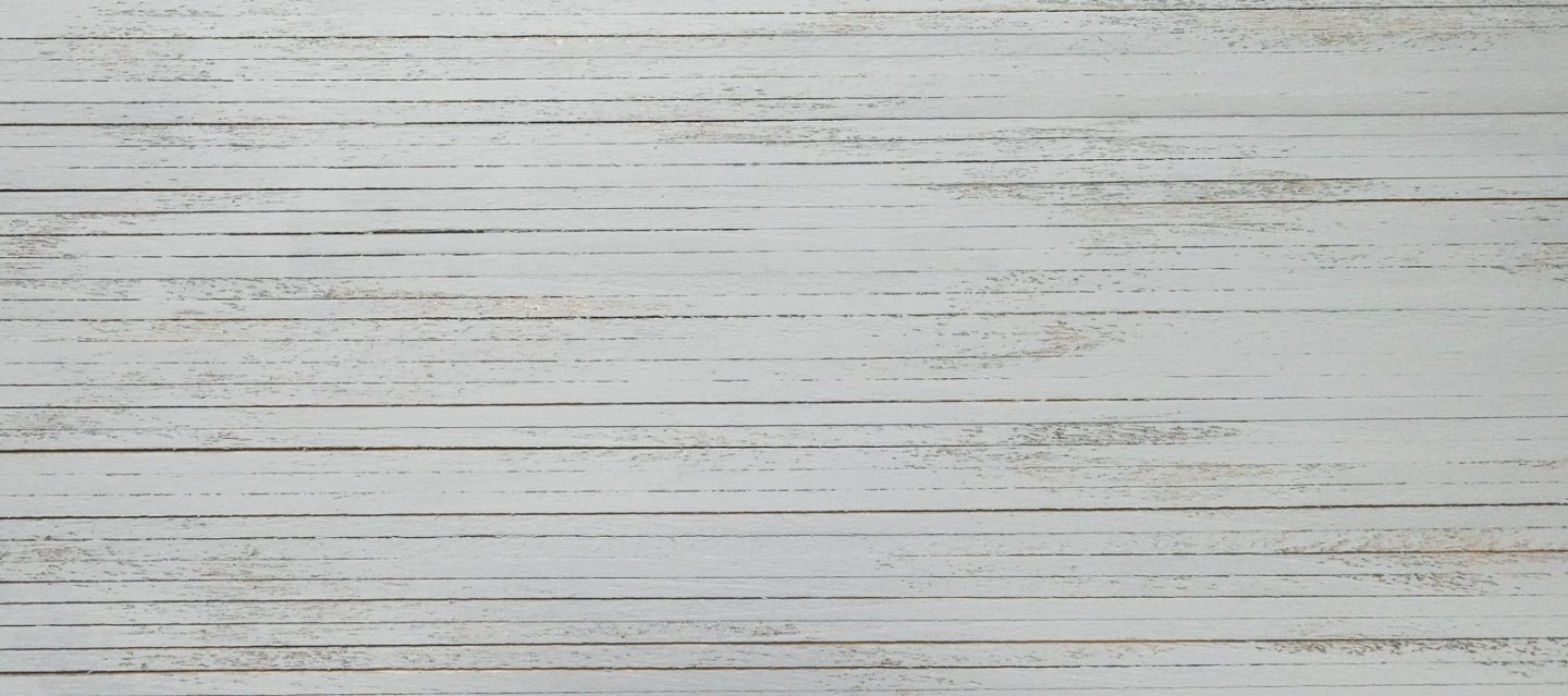
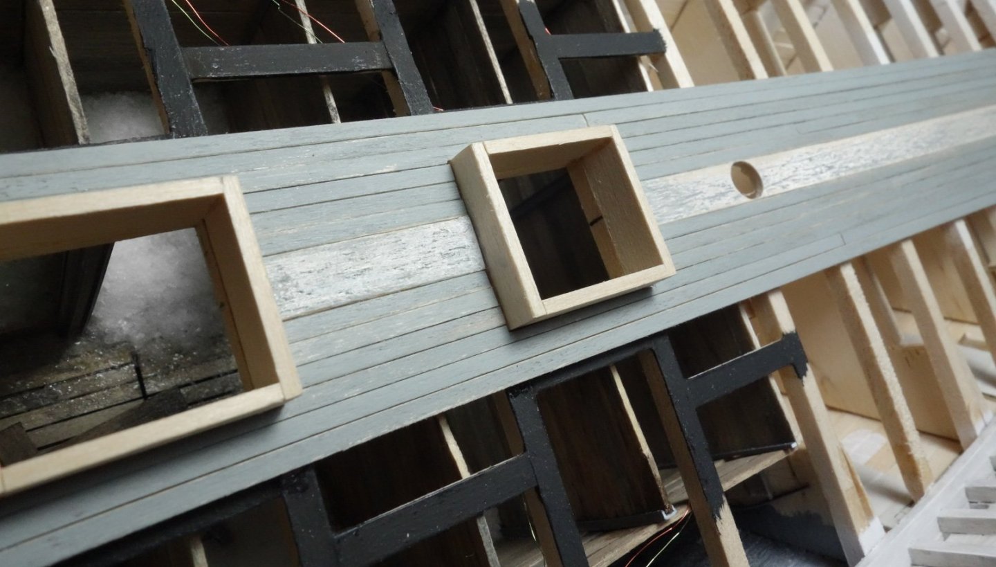
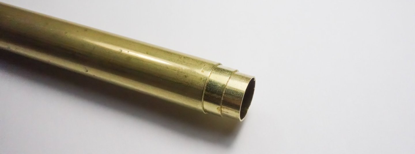
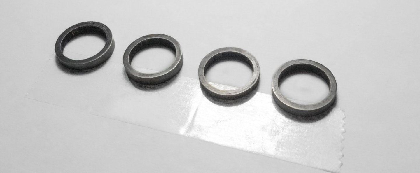
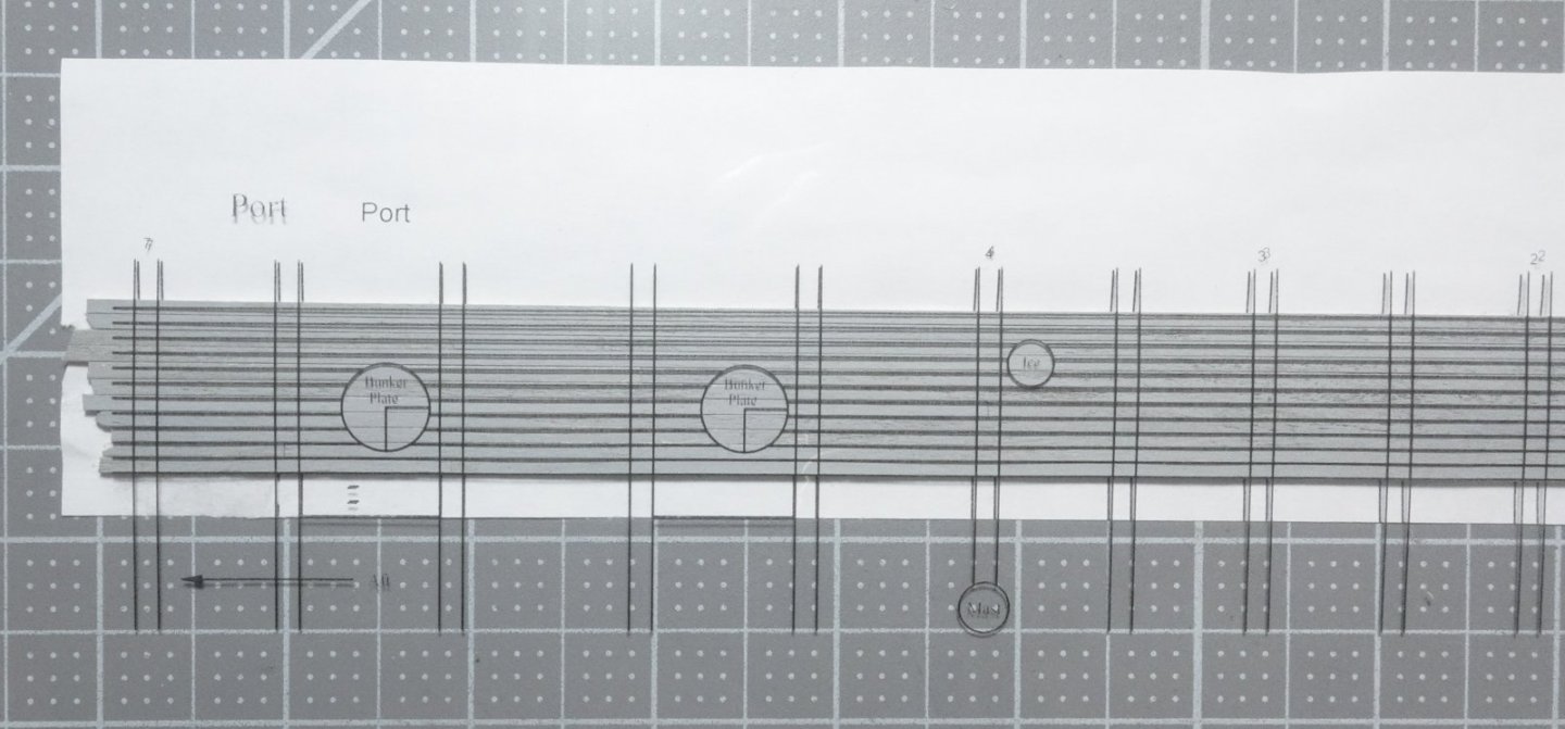
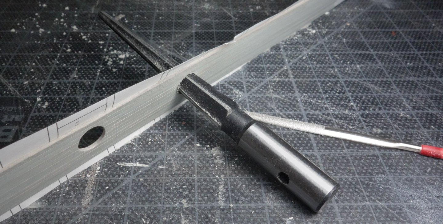
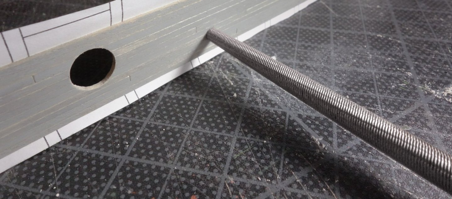
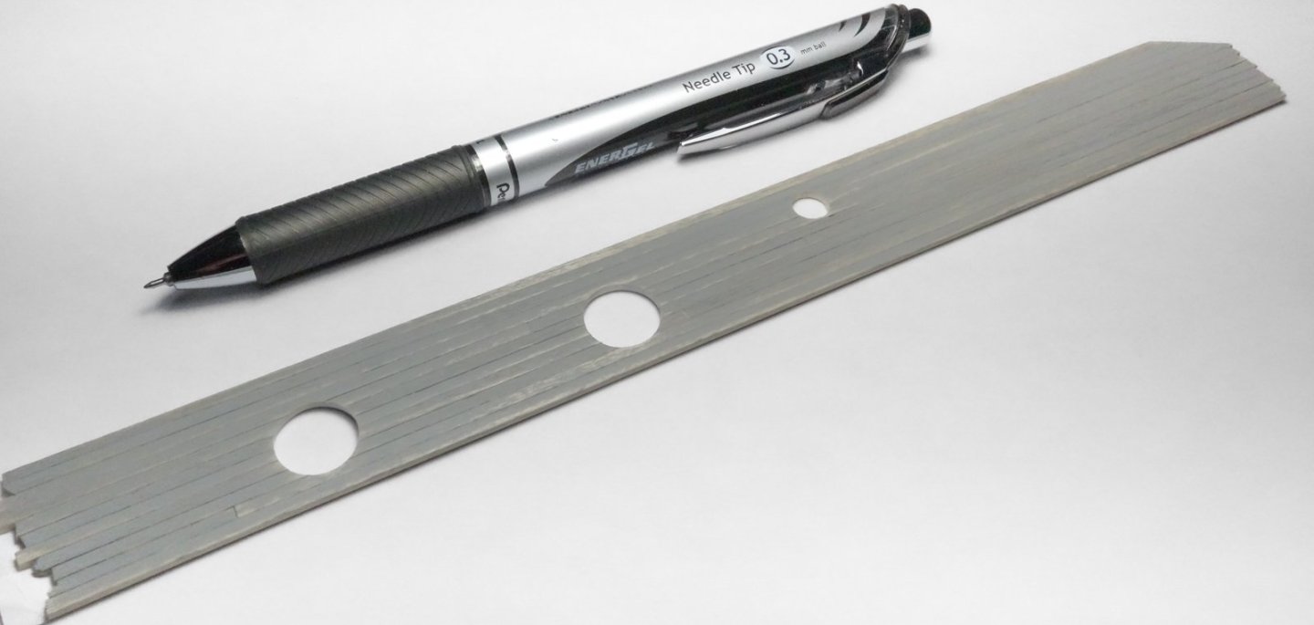
Greetings After several months of doing little on this model, I'm moving forward again. The covering boards have been installed forward of midships. They are pieced together between the top timbers and the inside margin is a single strip. I did it this way because the thick deck planks were difficult to cut crisply around the top timbers. But I would not do it this way again. The top timbers are irregularly spaced in this area to accommodate the freeing ports as per the plans. Airbrushed with thinned Tamiya flat white – 2:1. It looks gray below, but it is white. Later I added a little dirt with pigment powder. Coamings for the fish hold hatches were made from 12” x 3” material. From the side they are parallelograms to compensate for the deck sheer. These are only the lower portions of the coamings, and they will eventually be heightened to 21” above deck. The 12” king plank was placed and a hole for the forward mast was cut. The hole was first pilot drilled then carefully enlarged with a 1/4” burr chucked into a pin vice. The burr cuts too aggressively, so I turned it counterclockwise into the wood. The burr is abrasive enough that even being rotated in the opposite direction still burrows a smooth and perfectly round hole into the soft wood. The plank was painted white on top of gray then scraped with the edge of a safety razor set almost perpendicular to the plank. The deck planks are stained a natural wood color as a base. Then gray paint was scrubbed on top. I added about 10 percent yellow to shift it away from blue. I applied the paint heavier is some areas and practically dry-brushed on in others. I began adding deck planks from the center outward. The planks are 4” wide by 3” thick and were painted black on bottom and sides to help keep the fish hold lighting from escaping. This is not the final deck finish. After all the planking is installed, it will be repaired as needed, scraped, wear patterns added and weathered. This section of deck has four bunker plates and two smaller deck inlet plates. The lids for the bunker plates have already been made and the process that I used is shown back on post #124. They were made from polymer clay and enclosed by a perimeter brass ring. Similar to a manhole cover, these lids fit into ring frames. The frames are made of three slide fit brass tubes that combined provide the wall thickness required. Soldered. Cut from the tube and treated with Jax Flemish Gray. The lids are epoxied into the frames – one will be left open. The deck inlet plates are considerably smaller and have 10” dia. openings. The plans label the port side plate "ice" and is positioned over a walk-in refrigerator. The starboard plate passes coal to a bin in the galley next to the cook stove. The plates are made from brass tube, wire and styrene. I made a section of deck for each side of the boat and cut holes for the deck plates off model. I did this to avoid getting wood chips and sawdust down in the fish hold. I began by creating a positioning template in CAD. I glued planks directly to the template. I could have glued them to a blank sheet of paper, but this insured the edges were straight and the combined width was correct from end to end. I then printed the same drawing on laser transparency and used it to locate the cutouts. The bunker plate holes were drilled through then enlarged with a tapered reamer twisted counterclockwise. The edges were cleaned up with a diamond needle file. With a tapered round file, the same was done for the smaller inlet plates. Plates glued into place. The other side was done the same way. Thanks for looking. Be safe and stay well. Gary


-
Very nice progress, Rob. Hope you're feeling better soon. Gary
-
Very true, Glen. And as a sufferer myself, I was only offering some friendly intervention before it gets out of hand. Gary
- 185 replies
-
- 7
-

-
-
- Flying Dutchman
- Black pearl
- (and 2 more)
-
Very nice progress on Discovery, George. That's most likely about controlling the spread of freshwater Zebra Mussels. They are a destructive invasive species and problematic in many places in North America and indeed other continents. Free swimming larvae often attach themselves to hulls. Gary
-
She's looking really sweet, Paul! I like the base - long and thin like that graceful hull and it doesn't pull attention away from the model. Sort of minimalist. Gary
- 201 replies
-
- 5
-
-
-
- Oyster Sharpie
- first scratch build
- (and 1 more)
-
Such great workmanship, Keith. As others have said, the crew adds motion to the piece. Fantastic job - congratulations! I'm really looking forward to watching you bring Lula to life. Gary
-
Nice progress! Tricky figuring for unfolding the Dutchman. Sails look appropriately tattered - nice. Only a modeler would look at a dryer sheet and say to himself - "hey now, look at this material". You got the disease bad, Glen. Gary
- 185 replies
-
- 10
-
-
-
- Flying Dutchman
- Black pearl
- (and 2 more)
-
Very nice progress, John ! Gary