
Supplies of the Ship Modeler's Handbook are running out. Get your copy NOW before they are gone! Click on photo to order.
×

bruce d
-
Posts
3,020 -
Joined
-
Last visited
Content Type
Profiles
Forums
Gallery
Events
Everything posted by bruce d
-
 Not noticed a pump actually under a capstan before. I suppose it's an anchor boat, anything that works is OK.
 -
Well spotted Allan. Digging in records shows that she was fitted with a capstan while in Portsmouth dockyard between May and June 1745. It was at this time the lines were taken off and despite seeing pumps and stoves we do not see a windlass. Mediator had been roughed up when captured by a French privateer off the Needles and then suffered further bruises when re-taken by the RN the following day. She was needed back in convoy service urgently and repairs were quickly authorized plus instructions given to record her lines. Despite the artist meticulously recording other details (such as the miss-matched stern windows which reconcile with hasty repairs) I saw no hint of a previous windlass in the correspondence or the plans. If it hadn't been for the capture by the privateer and re-capture the following day there would be no drawings. NMM describes her as 'purchased' but this is not entirely accurate. She was owned by a RN officer who bought her in the West Indies and contracted her to the RN for the supply crisis. She foundered and was lost at Ostend in a storm just a few weeks after release to duty from Portsmouth dockyard. I will eventually write the tale and post it.
-
Eberhard, The keel is a little wider than the plywood former so will become a useful part of the puzzle. I am planning on tacking a dummy in place for the planking to be replaced later. Also, I am counting on being able to finish the rabbet with the dummy in place. Very sensible comments on the hardness of the fillers, thanks.
-
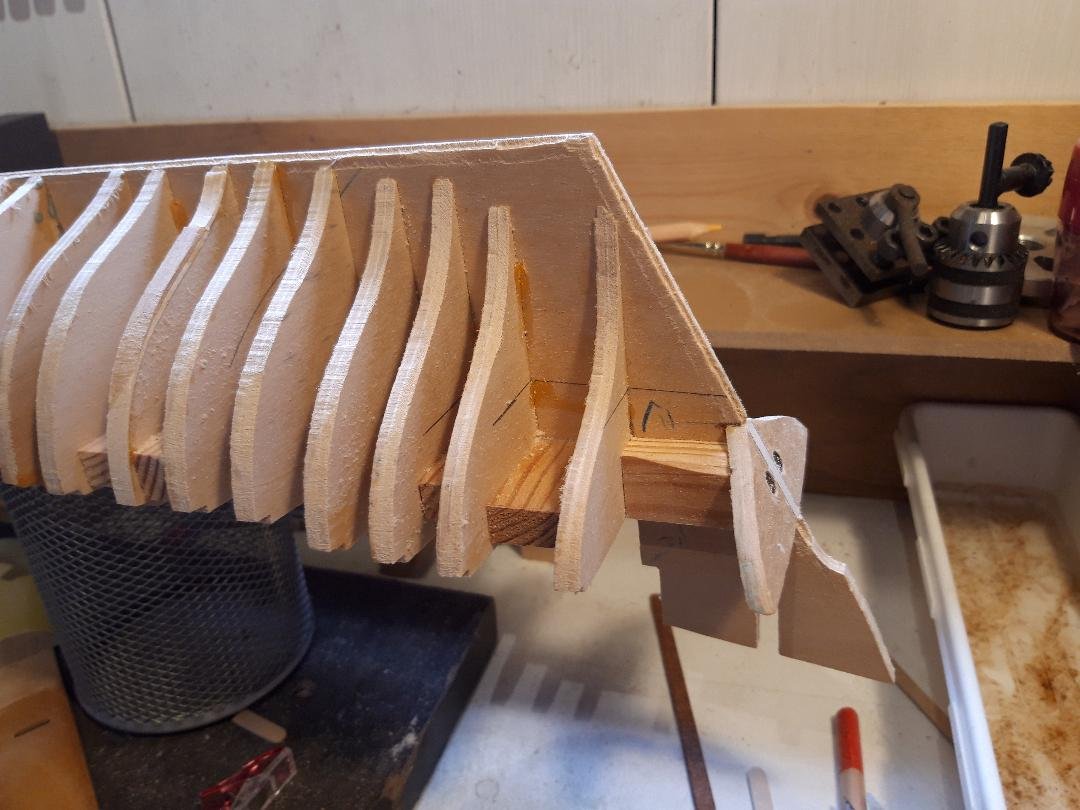
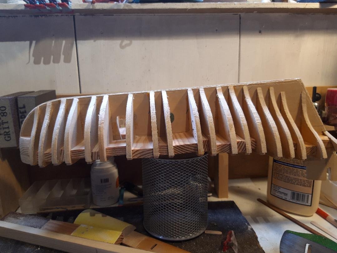
I am doing my first ever fairing of a POB model (scratch built Mediator from Jeff Straub plans). My gut feeling is that I should have fillers between some of the bulkheads where the gap is greatest and/or the lines change. The bow fillers are necessary but my lack of experience leaves me seeking advice about the rest of the hull and stern. As the shape emerges from my sanding efforts it seems now is the time if it is going to happen. Common sense says to use wood softer than the bulkheads. Are there any negatives or cautionary tales about bulkhead-fillers? Thanks in advance, Bruce
-
I agree it would be nice on one level but as Steven says it would be complicated. I believe it is a good idea for everyone to put their location, at least their country, in the spot below their avatar. This helps. What are you looking for?
-
11 anni di modellismo d'arsenale
bruce d replied to MICHELE PADOAN's topic in New member Introductions
Michele, welcome to MSW. Those models are magnificent and I hope you will share a build log with us. I am with everything of course but especially your carving. May I ask what is your method? Bruce -
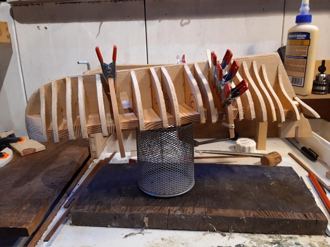
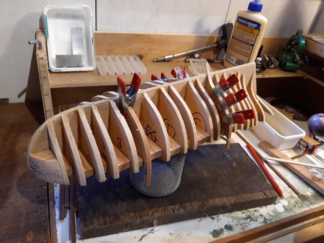
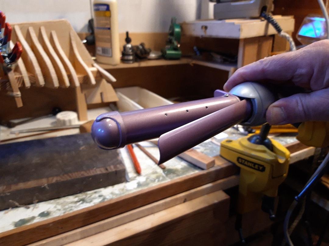
Thanks Guy, cautionary tales are always welcome in this thread but I have already been ambushed by printer-woes, see post#2, and it is possible they have surfaced again (but I am getting a bit ahead of myself). Fairing is moving ahead and has required a bit of fettling: there are a few low spots and I have been adding material. There is something about bulkhead number 5 that is odd. On both the Mark 1 Mediator, the one that I started and then stopped, and now on this second attempt, bulkhead #5 is low. I don't see how it is a printer issue as the piece is the correct height. Bulkhead #A is also affected, again on both Mk 1 and Mk 11, but far less noticeably. I was careful when cutting out the bulkheads for Mk 11 and am satisfied that the piece matched the drawing before I started assembly. Yet, here we are again. At an appropriate moment I will check the master drawings and the scans I made but ... I suggest anyone considering building Mediator leaves a bit of extra material around these two bulkheads. There is nothing obviously wrong with the shape, just that when the formers and bulkheads are assembled #5 is low by about 2mm, #A about 1mm in a short section. No biggie, just something that is avoidable. After trying a couple of different woods and bending methods I settled on using coffee stir-sticks and hair tongs. The results were perfect from my point of view because the wood, which may be birch, is of a similar hardness to the ply used for the bulkheads. This is a useful feature when sanding. I wet the stir-stick for a minute or so and then roll it around the heated tong free-hand. It is quick and effective. Clamps and rubber bands do the holding. One 'top tip' for anyone wanting to do it this way: have a look at the way the tongs were intended to be used. The tubular body of the tong heats up and the moving part that pinches the hair is spring loaded to hold the hair while drying/curling. This moving 'finger' gets heated by being in close contact with the hot tube. Put the wood to be bent between the two hot pieces, making sure the wood stays in close contact with the 'finger', and it heats the wood from both sides making a neater and more predictable result. Now if only I had some hair to try out my new skills ...
- 43 replies
-
- 5
-

-
- mediator
- first build
- (and 1 more)
-
"Evolution in Naval Architecture During the Reign of Queen Victoria." Text of the Watt Anniversary Lecture, January 1887 mrrobertduncano00duncgoog.pdf
-
- 3
-
-

-
Hello Giuseppe and a warm welcome to MSW from the UK.
-
Nils, you would have many friends drop in if you do that! The fish look as good as the boat, well done.
-
You will check in with us occasionally, just to let us know everything is alright? 🤐
-
Absolutely, Ab. Many thanks.
-
👍
-
Hello Mark, Sorry to hear yet another tale on this subject. There are plenty of good suppliers out there but it would help to know where you are since this affects which suppliers are relevant. Bruce
-
...but that was your seat whatever nature throws at you. As I understand it, outside seating was even sold on the longer routes and it was entirely up to the inside passengers (who had paid more) whether they would allow any of these 'top riders' inside even in the hottest or wettest weather.. Hollywood doesn't address this often.
-
ancre Le Gros Ventre by ChrisLBren - 1/36
bruce d replied to ChrisLBren's topic in - Build logs for subjects built 1751 - 1800
Well done, and I am humiliated by your neat workspace. Mind if I follow? -
From Military Collector & Historian: Vol 10 Iss 2 Summer 1958 THE EARLY COLUMBIADS by Colonel Cary S. Tucker, USA, Ret’d.
- 1 reply
-
- 2
-
-
-
Nils, that is a good looking model. What is next 😁 ? Regards, Bruce
- 180 replies
-
- 3
-
-
- pilot boat
- Elbe 5
- (and 3 more)
-
Hello Wieslaw, and welcome to MSW.
-
Thanks, that is clear, but .... at the risk of thread drift, was there anything that specifically covered ships/craft bought into the RN after 1778? In a fleet, such a vessel would potentially be surrounded by ships with their names displayed in one or other of the styles discussed above and it seems likely that conformity would be expected. Anything known about this specific point, such as deference to local command preferences? (Possibly this would be better in a dedicated thread but here we are, sorry about that.}
-
Screwed up
bruce d replied to gregkthompson's topic in Building, Framing, Planking and plating a ships hull and deck
Just an observation: Gorilla as a brand offers several 'wood' glues besides the original urethane bubbling stuff. If the Gorilla Wood glue on your model is PVA based (it will say somewhere on the label) then it can be softened with IPA as described earlier. I have heard the Gorilla range now even includes a seccotine product. Good luck, hope you keep us up to date with your progress. -
Seriously???? You have to ask????? Put me down for a copy, just let me know when it is out.
