DONATION DRIVE - SUPPORT MSW - DO YOUR PART TO KEEP THIS GREAT FORUM GOING!
×

bruce d
-
Posts
3,044 -
Joined
-
Last visited
Content Type
Profiles
Forums
Gallery
Events
Everything posted by bruce d
-
 Absolutely, Ab. Many thanks.
 -
👍
-
Hello Mark, Sorry to hear yet another tale on this subject. There are plenty of good suppliers out there but it would help to know where you are since this affects which suppliers are relevant. Bruce
-
...but that was your seat whatever nature throws at you. As I understand it, outside seating was even sold on the longer routes and it was entirely up to the inside passengers (who had paid more) whether they would allow any of these 'top riders' inside even in the hottest or wettest weather.. Hollywood doesn't address this often.
-
ancre Le Gros Ventre by ChrisLBren - 1/36
bruce d replied to ChrisLBren's topic in - Build logs for subjects built 1751 - 1800
Well done, and I am humiliated by your neat workspace. Mind if I follow? -
From Military Collector & Historian: Vol 10 Iss 2 Summer 1958 THE EARLY COLUMBIADS by Colonel Cary S. Tucker, USA, Ret’d.
- 1 reply
-
- 2
-

-

-
Nils, that is a good looking model. What is next 😁 ? Regards, Bruce
- 180 replies
-
- 3
-
-
- pilot boat
- Elbe 5
- (and 3 more)
-
Hello Wieslaw, and welcome to MSW.
-
Thanks, that is clear, but .... at the risk of thread drift, was there anything that specifically covered ships/craft bought into the RN after 1778? In a fleet, such a vessel would potentially be surrounded by ships with their names displayed in one or other of the styles discussed above and it seems likely that conformity would be expected. Anything known about this specific point, such as deference to local command preferences? (Possibly this would be better in a dedicated thread but here we are, sorry about that.}
-
Screwed up
bruce d replied to gregkthompson's topic in Building, Framing, Planking and plating a ships hull and deck
Just an observation: Gorilla as a brand offers several 'wood' glues besides the original urethane bubbling stuff. If the Gorilla Wood glue on your model is PVA based (it will say somewhere on the label) then it can be softened with IPA as described earlier. I have heard the Gorilla range now even includes a seccotine product. Good luck, hope you keep us up to date with your progress. -
Seriously???? You have to ask????? Put me down for a copy, just let me know when it is out.
-
Hello Nils, it is looking good. Glad to hear you are recovering. Bruce
- 180 replies
-
- 2
-
-
- pilot boat
- Elbe 5
- (and 3 more)
-
Looking for pre-made sails for Mamoli Britannia
bruce d replied to Bob Lowther's topic in Wood ship model kits
Hello Costas, Welcome aboard! Britannia is a popular subject and I am sure you will find someone here has useful advice. Can I suggest you post a bit about yourself in the New Members Introduction thread? Link : New member Introductions - Model Ship World™ A build log will also get attention on your project, that is a great way to chat to other people who can see your progress. Regards, Bruce -
I believe this would be classified under 'non-habit forming activity'.
-
Thanks, I have not used either so must ask: are they the same basic material? It is useful to know that you have used the ModelSpan but the processes described are used on Silkspan, I am wondering if the ModelSpan material would perform in the same way with the same results when the same processes are used. I like the results and would like to replicate them. 👍to Ron.
- 542 replies
-
- 1
-
-
- Sphinx
- Vanguard Models
- (and 3 more)
-
Is there a Silkspan equivalent product available in the UK (or a friendly EU source)?
- 542 replies
-
- 1
-
-
- Sphinx
- Vanguard Models
- (and 3 more)
-
Mariner's Astrolabe, full scale, AON
bruce d replied to AON's topic in CAD and 3D Modelling/Drafting Plans with Software
Alan, you have made something very nice, well done. Also, you may have started something. Here is an astrolabe that was illustrated and described in the Nautical Research Journal vol 2, issue 1 (1950): An astrolabe is not on my to-do list (well, ok, you got me thinking about it), but there is an equinoctial sundial creeping up the queue. Bruce- 36 replies
-
- 4
-
-
-
- Navigation
- Instrument
- (and 1 more)
-
A treatise on the Anchor 1819, by Richard Pering. At the end are tables of weights and dimensions for each rate of ship down to cutters. Pering was Clerk of the Cheque of HM Dockyard, Plymouth. A_Treatise_on_the_Anchor_and_a_Schedule (1).pdf
- 1 reply
-
- 5
-
-
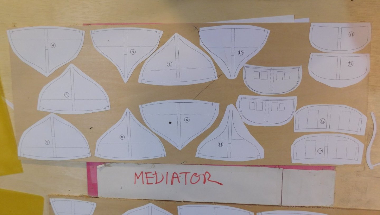
I originally had a set made at a local print shop which I cut up and scanned on my home setup. After some jiggery with the resultant scale issues, I printed off whatever was appropriate for the bits I was working on: card, paper, mirror image etc. Before I pulled the trigger on the re-start I had a new set printed full size. So far, I haven't needed them but we shall see ... Bruce
- 43 replies
-
- 2
-
-
- mediator
- first build
- (and 1 more)
-
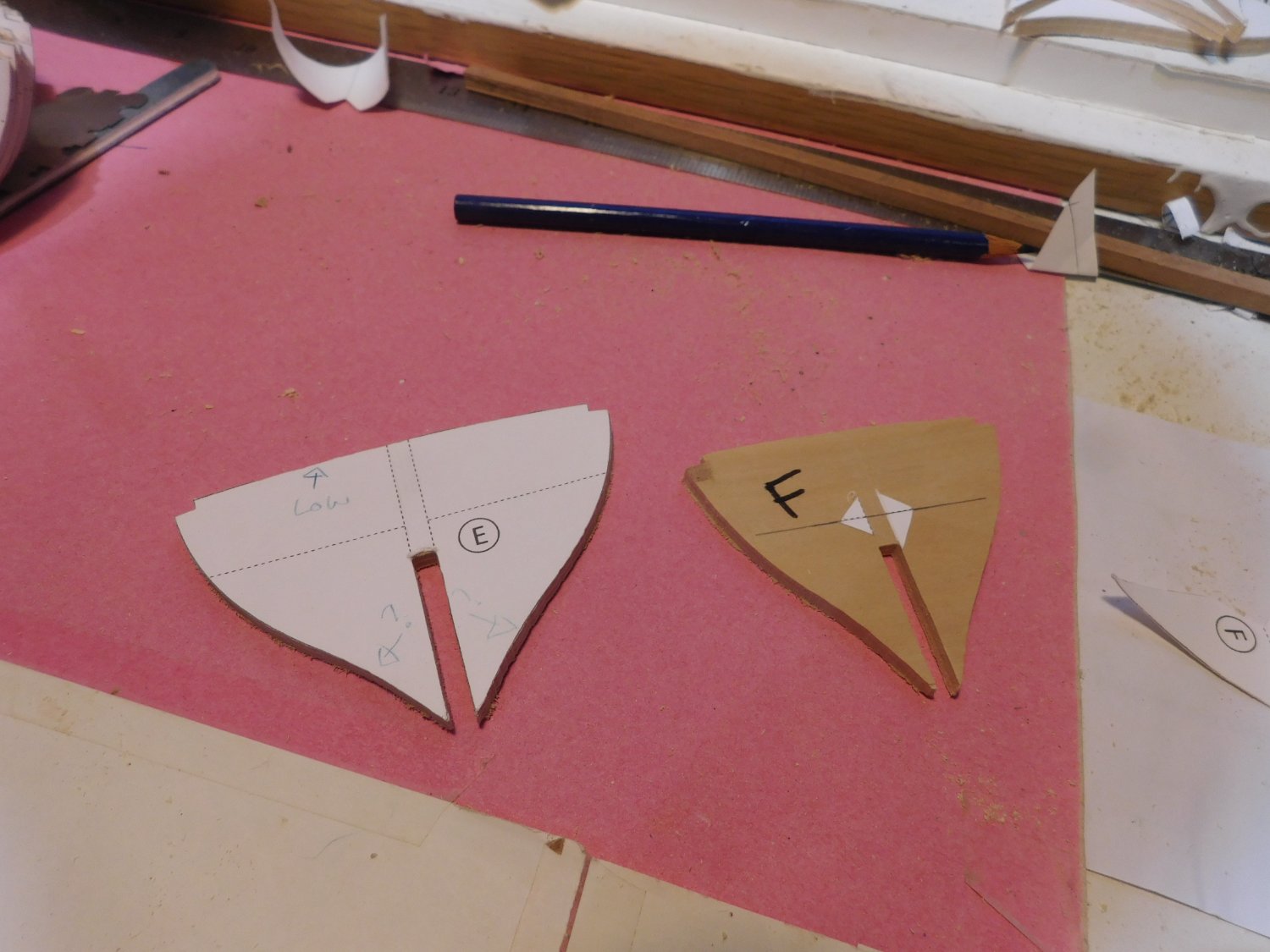
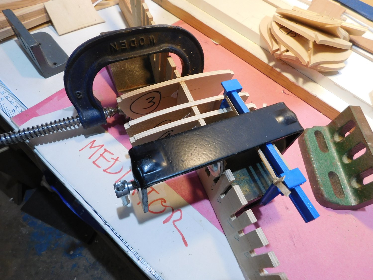
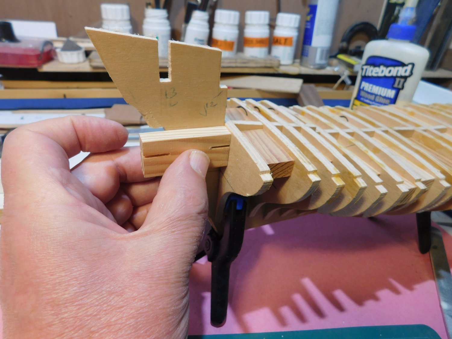
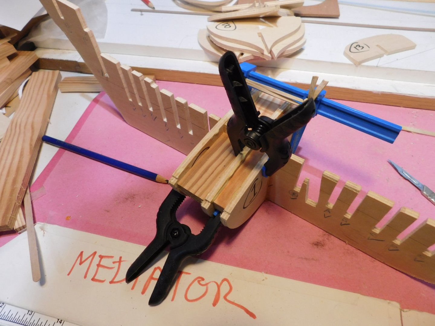
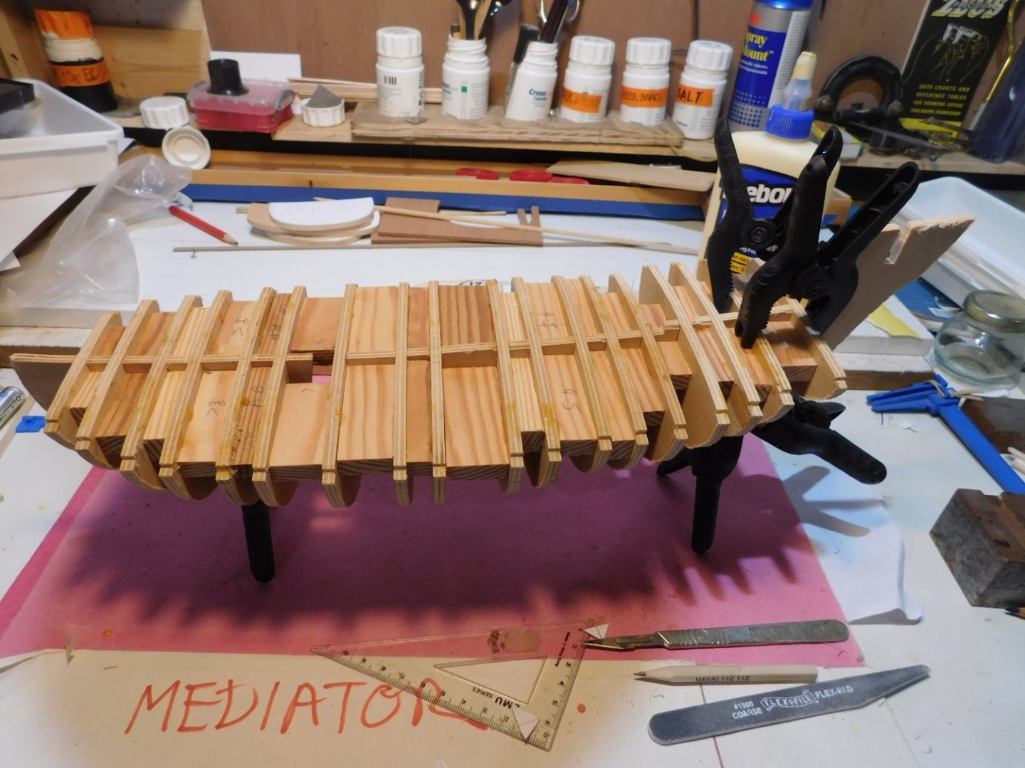
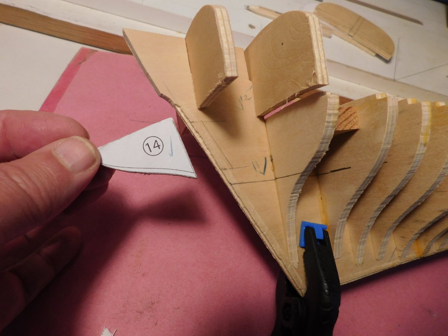
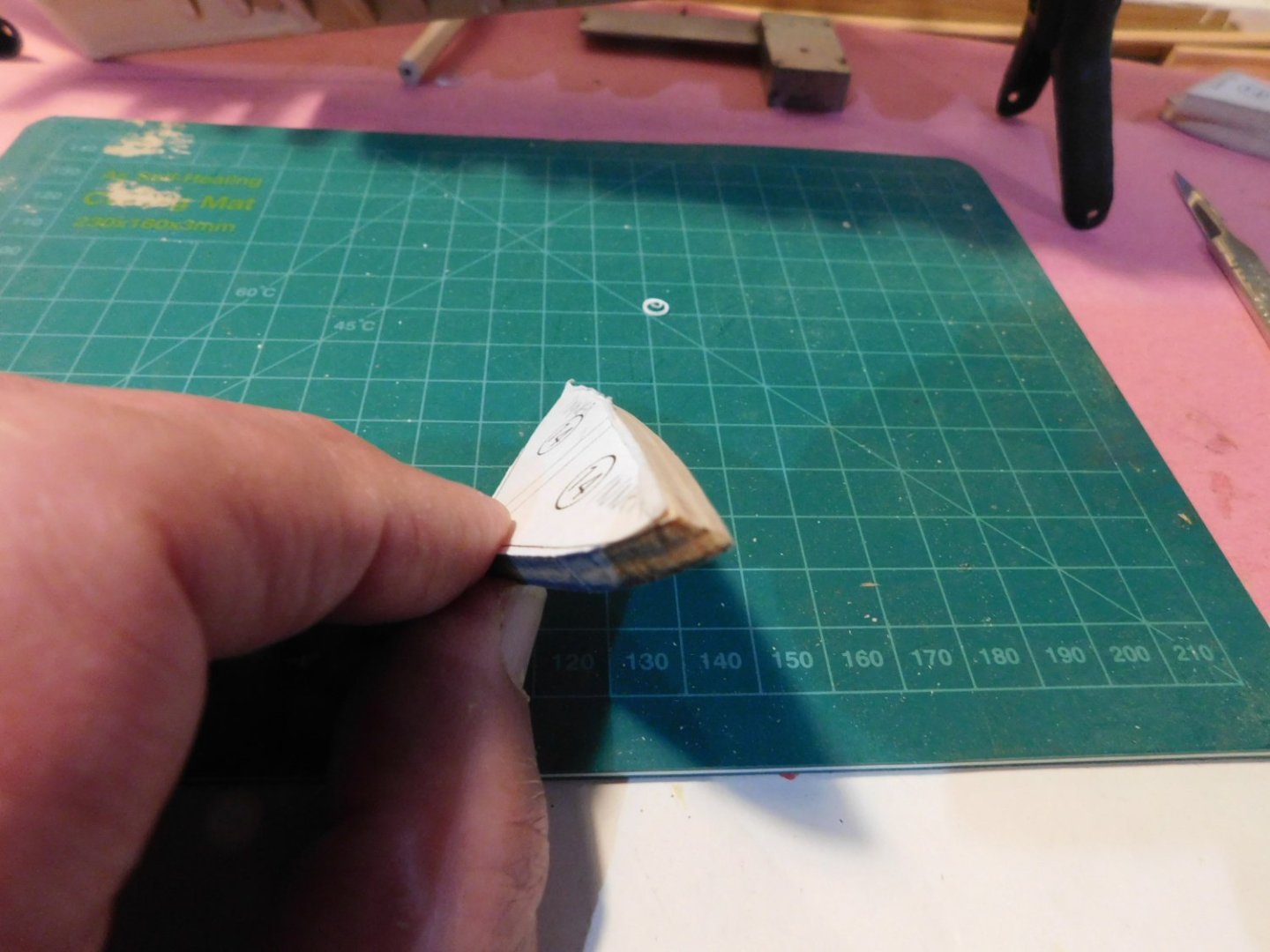
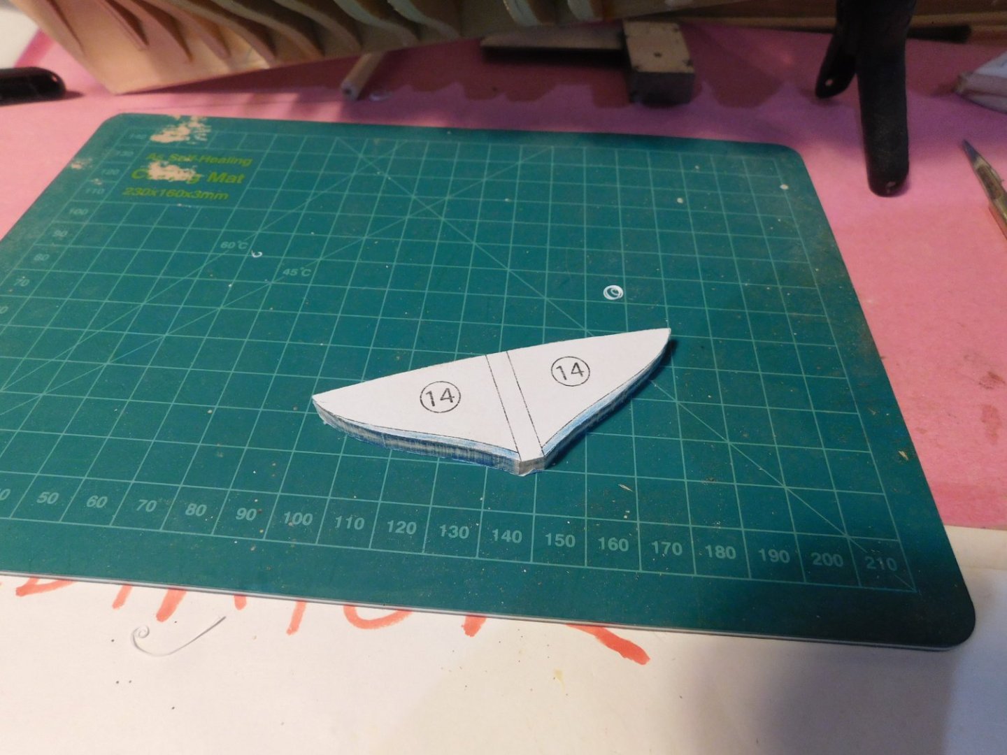
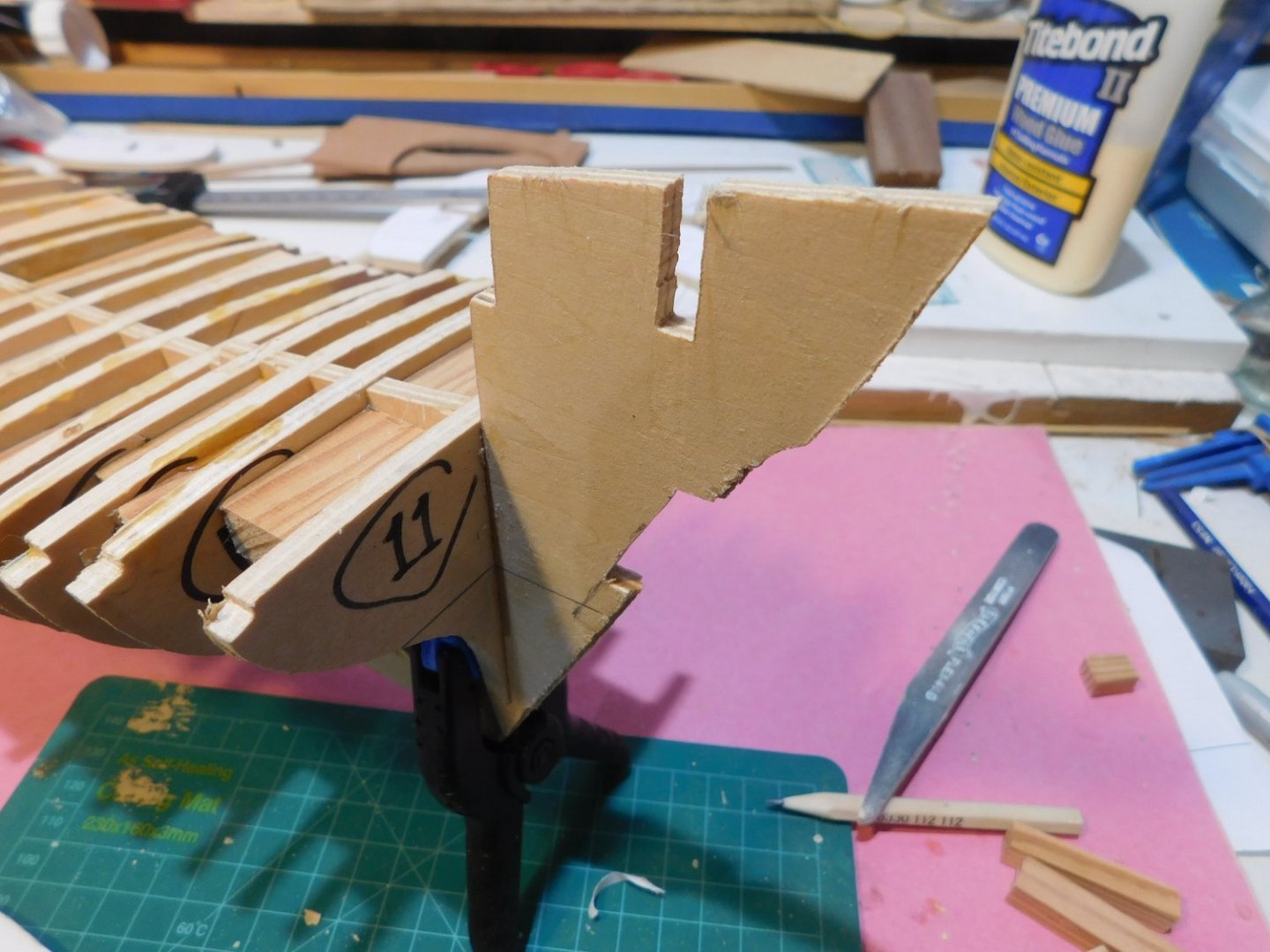
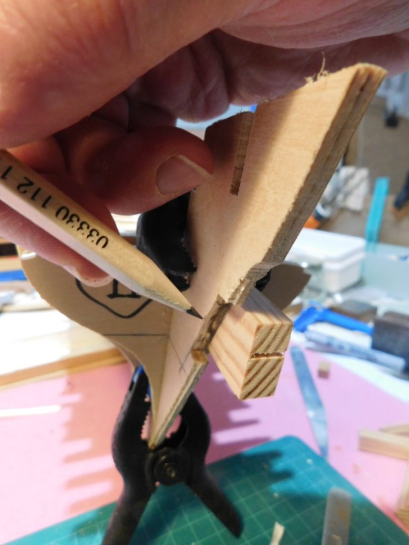
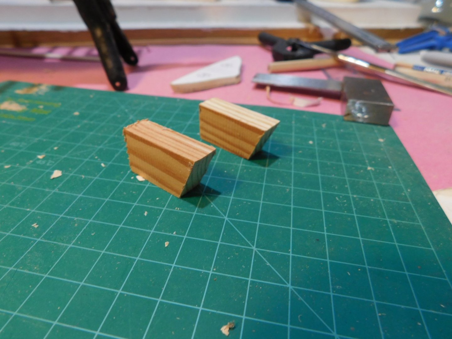
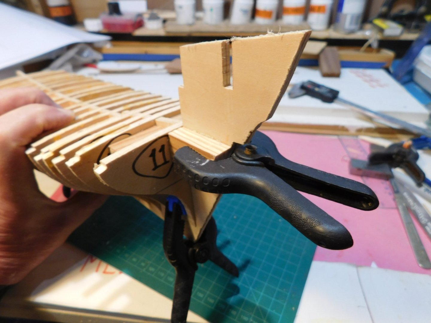
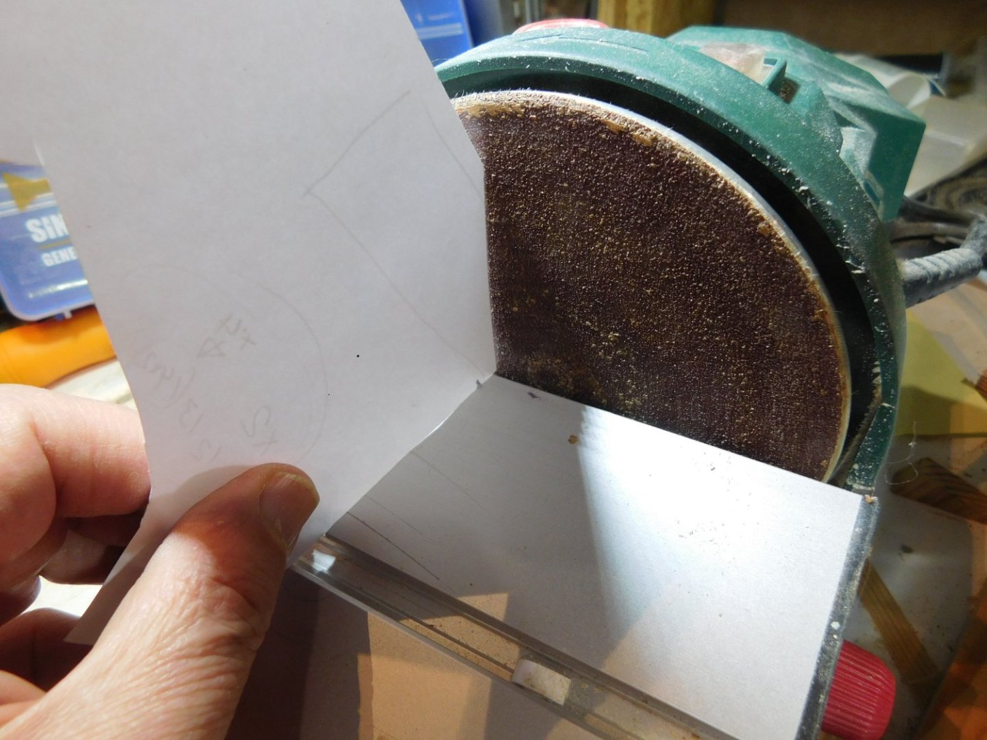
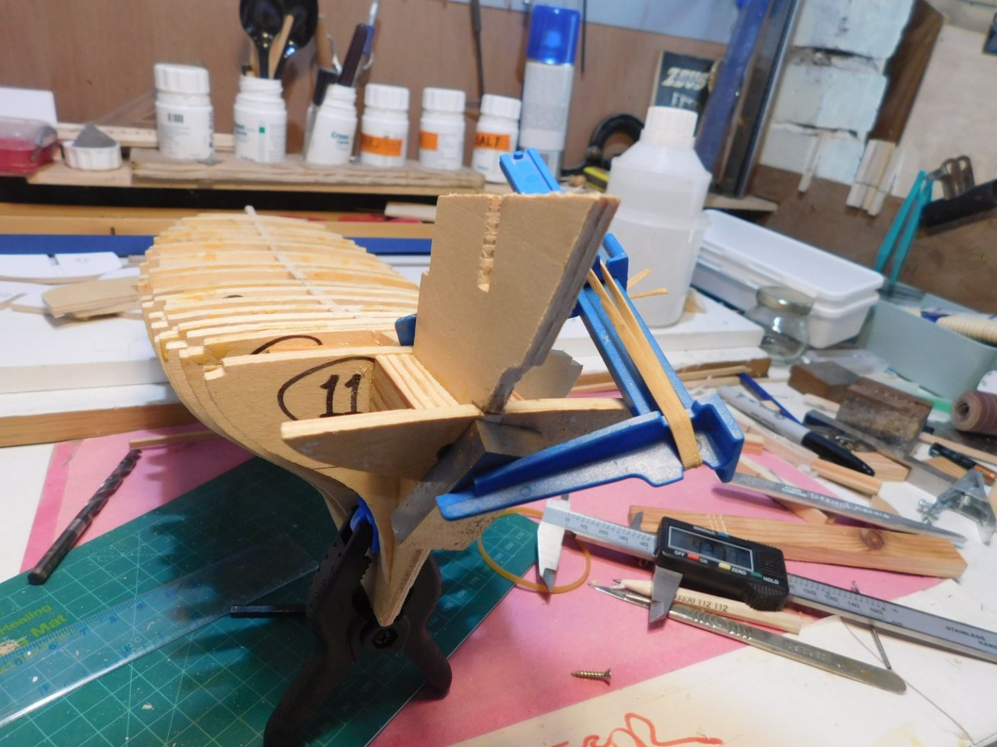
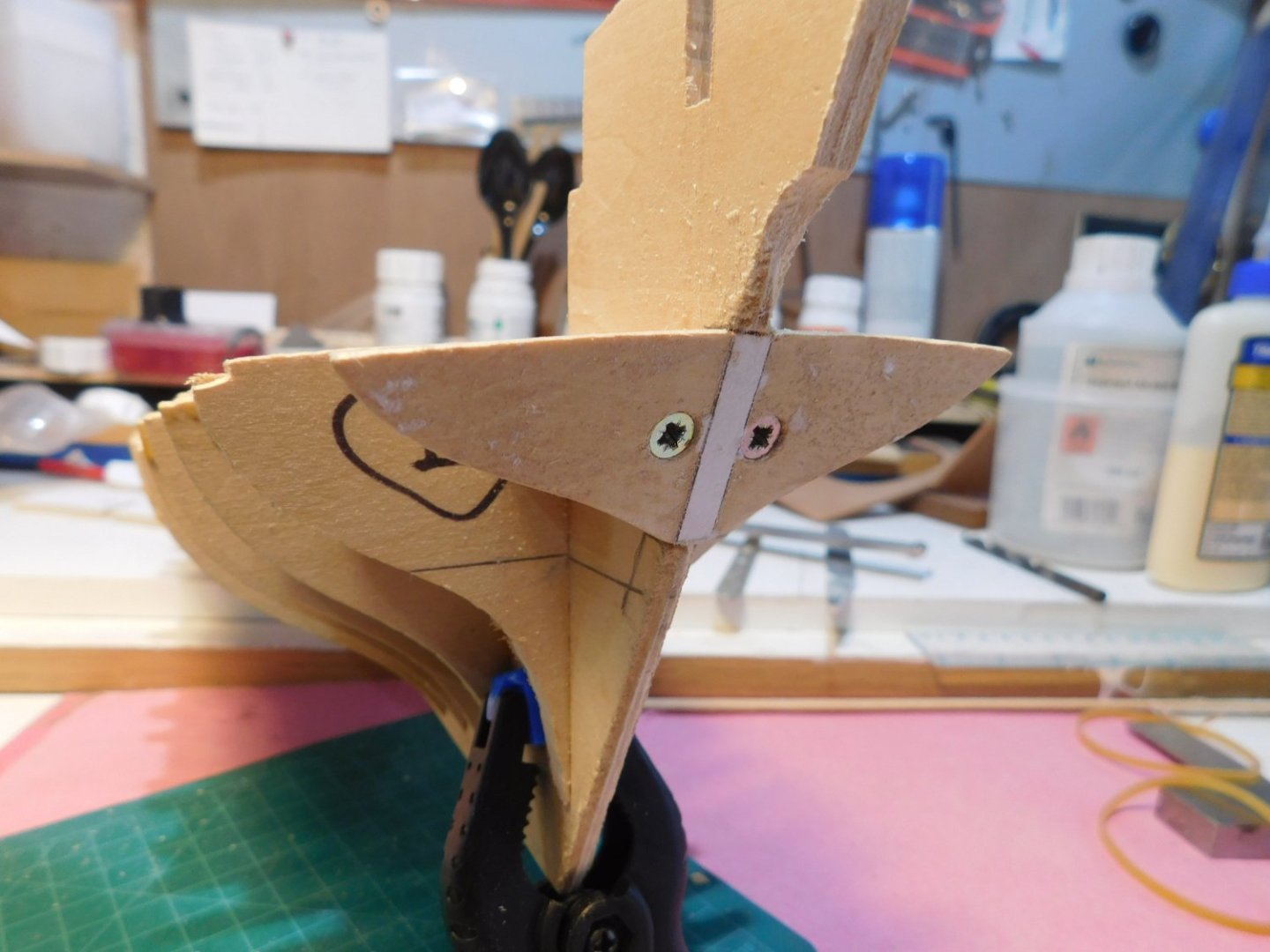
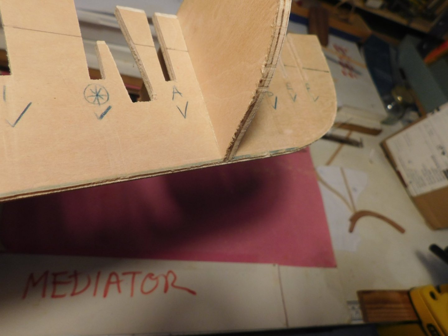
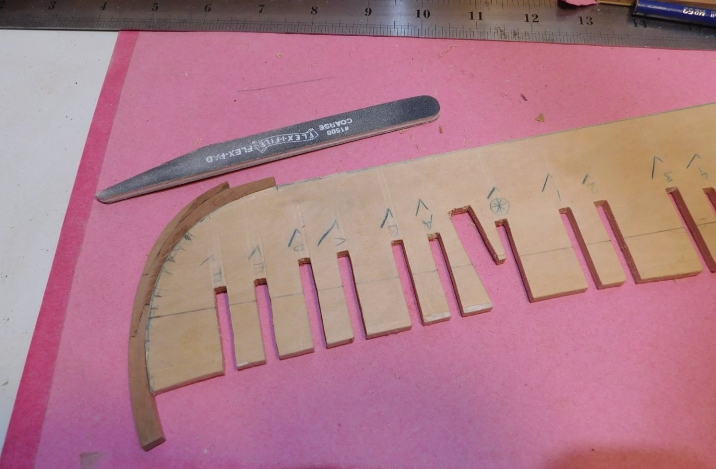
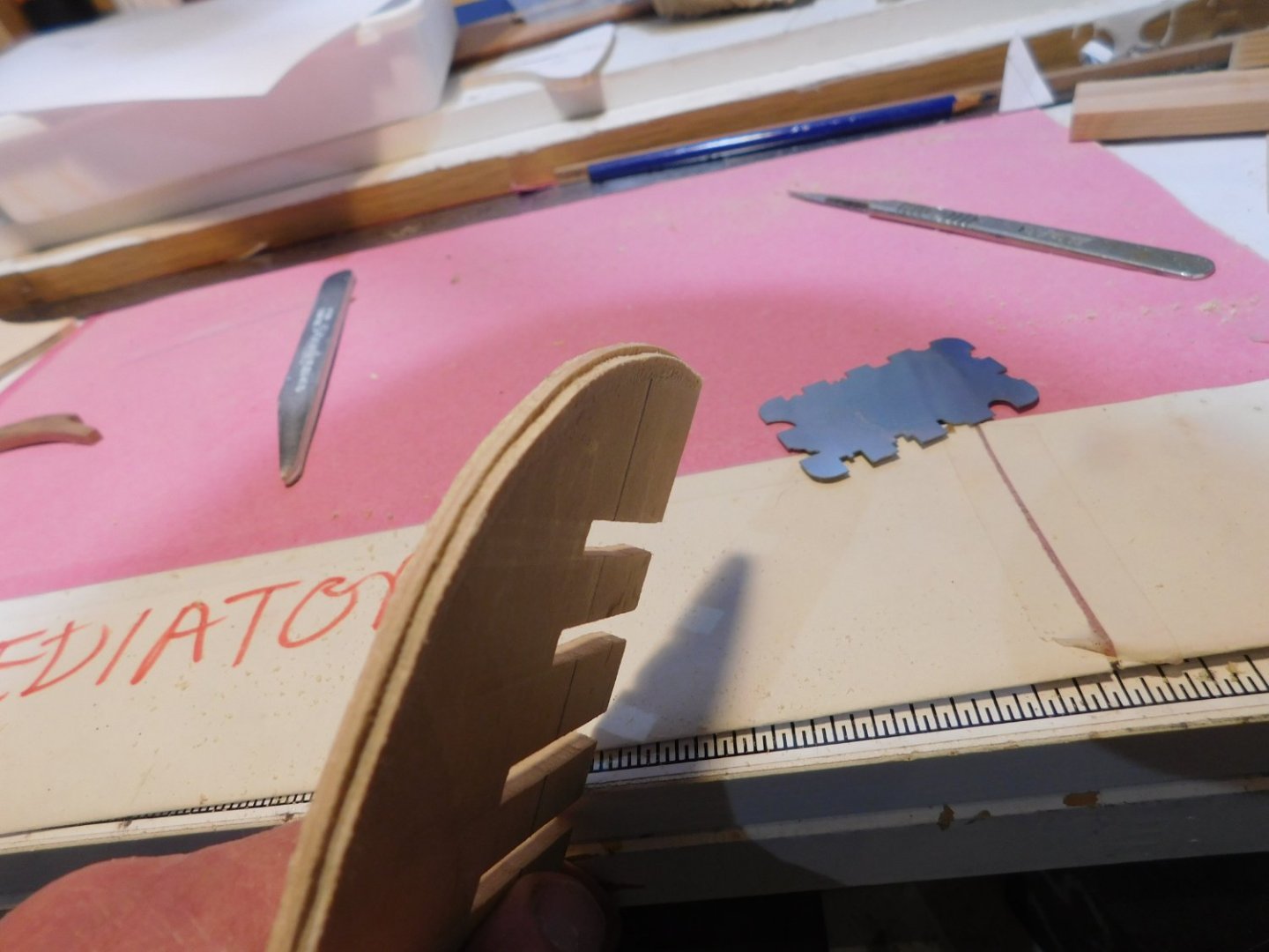
Next, a dry-fit and final fettle of the frames. Passed the test, time to get the glue out. Frames were marked with WL and checked. Fitting the frames dead square Spacers were cut dead square from some stable stock to fit snugly between the frames. The method used was to cut a piece that was a snug fit where the frame meets the hull former and then cut it in two, one piece for each side (good old Byrnes saw). All frames for the main body of the hull in place, square and rigid. The stern-most frames which form the shape of the cabin were worked to shape and tested but set aside until later. Second deviation: The plans call for part #14 to be made as two identical but mirrored pieces to be mounted (how is not explained) at the stern. Thinking about the fairing and planking ahead this seemed fragile so … I made this as one piece and cut a slot for it in the stern. I thought about doing this on the bandsaw at the same time as the rest of the slots for the frames but decided to do it after all the frames were glued up so I could study the lines and shape more closely and do some of the fairing of this ‘new’ piece #14 off the model. The part #14 as drawn: My single piece version: I put paper templates on both sides of #14 and marked what needed to come off top, bottom and sides. Copied the angle of #14 relative to the WL and set the disc sander accordingly. Steady hand and baby-steps, looks like it worked well. Glued and screwed the now beveled #14 in place against wood fillers, should be strong enough to survive my attempts at fairing. Fairing is coming soon, first I have to dry fit the cabin frames to the top-side to get the stern-shape straight in my head.


- 43 replies
-
- 7
-
-
- mediator
- first build
- (and 1 more)
-
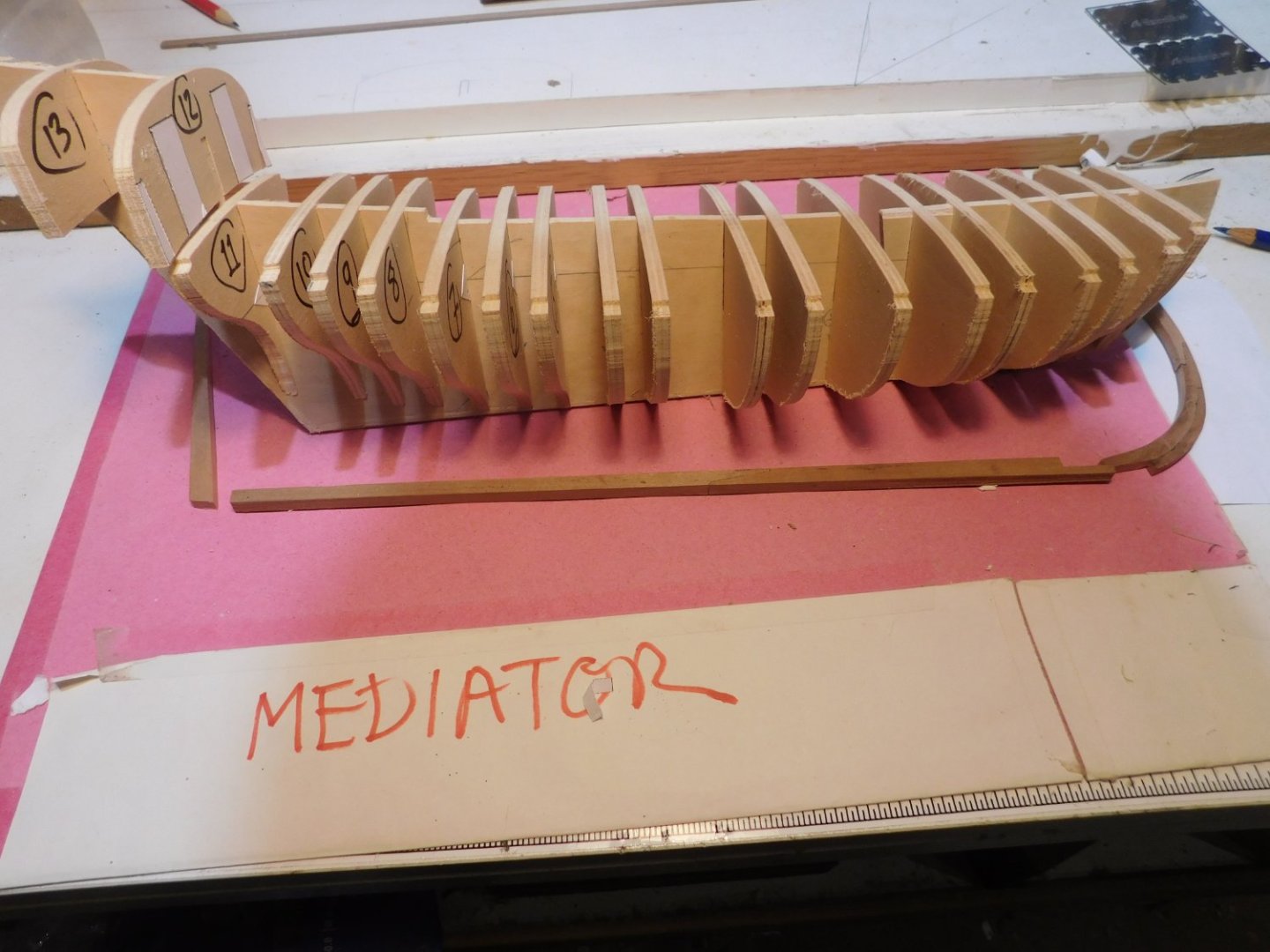
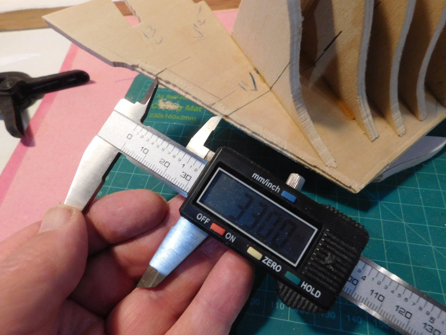
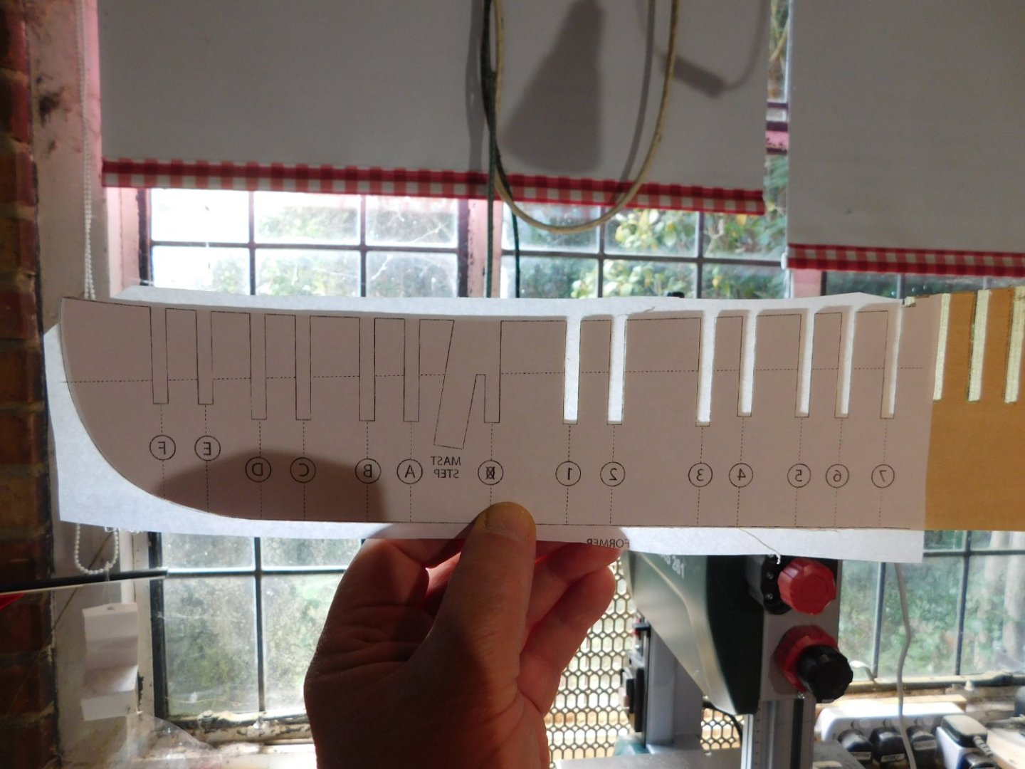
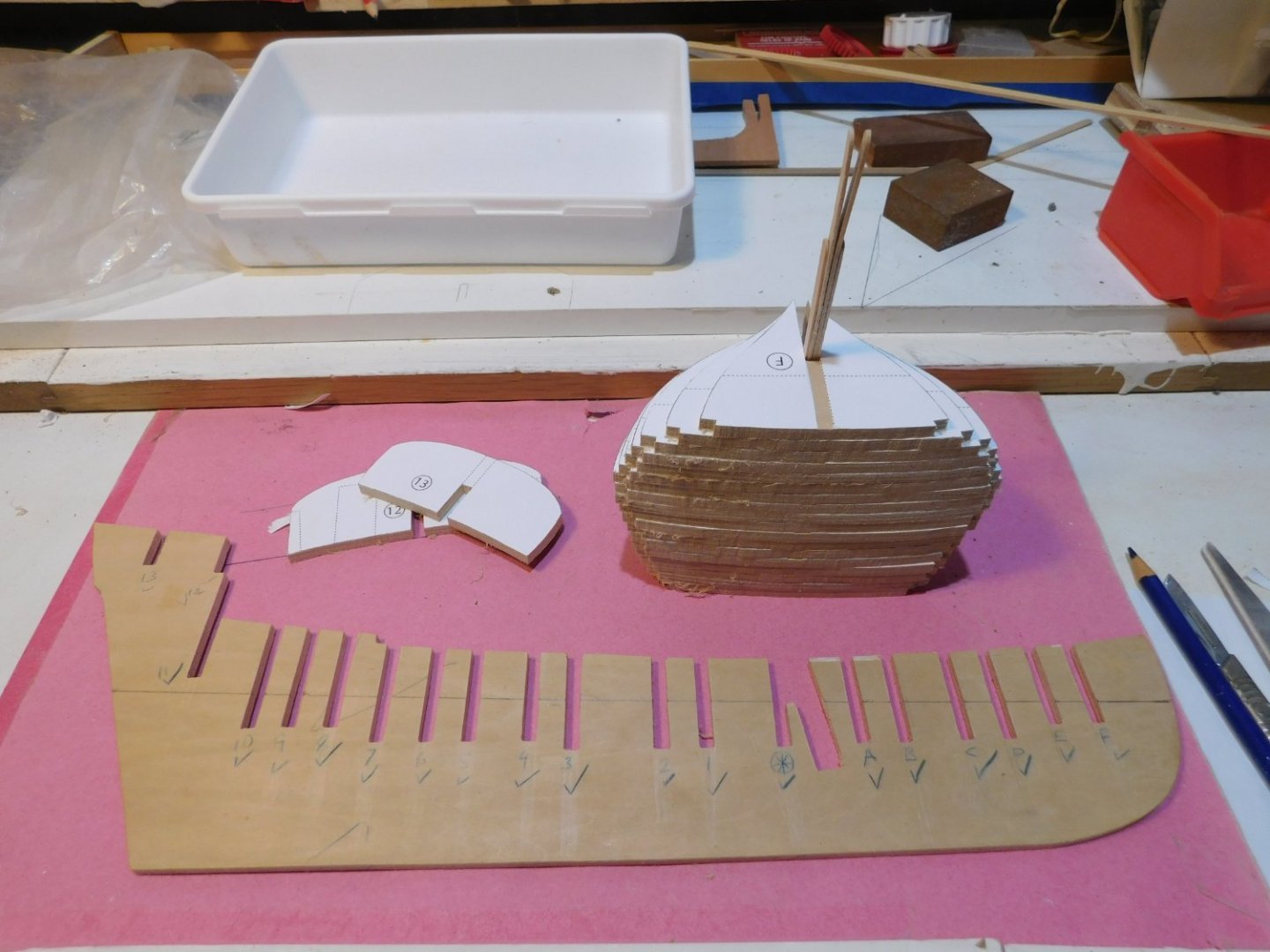
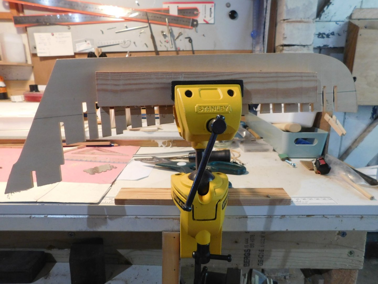
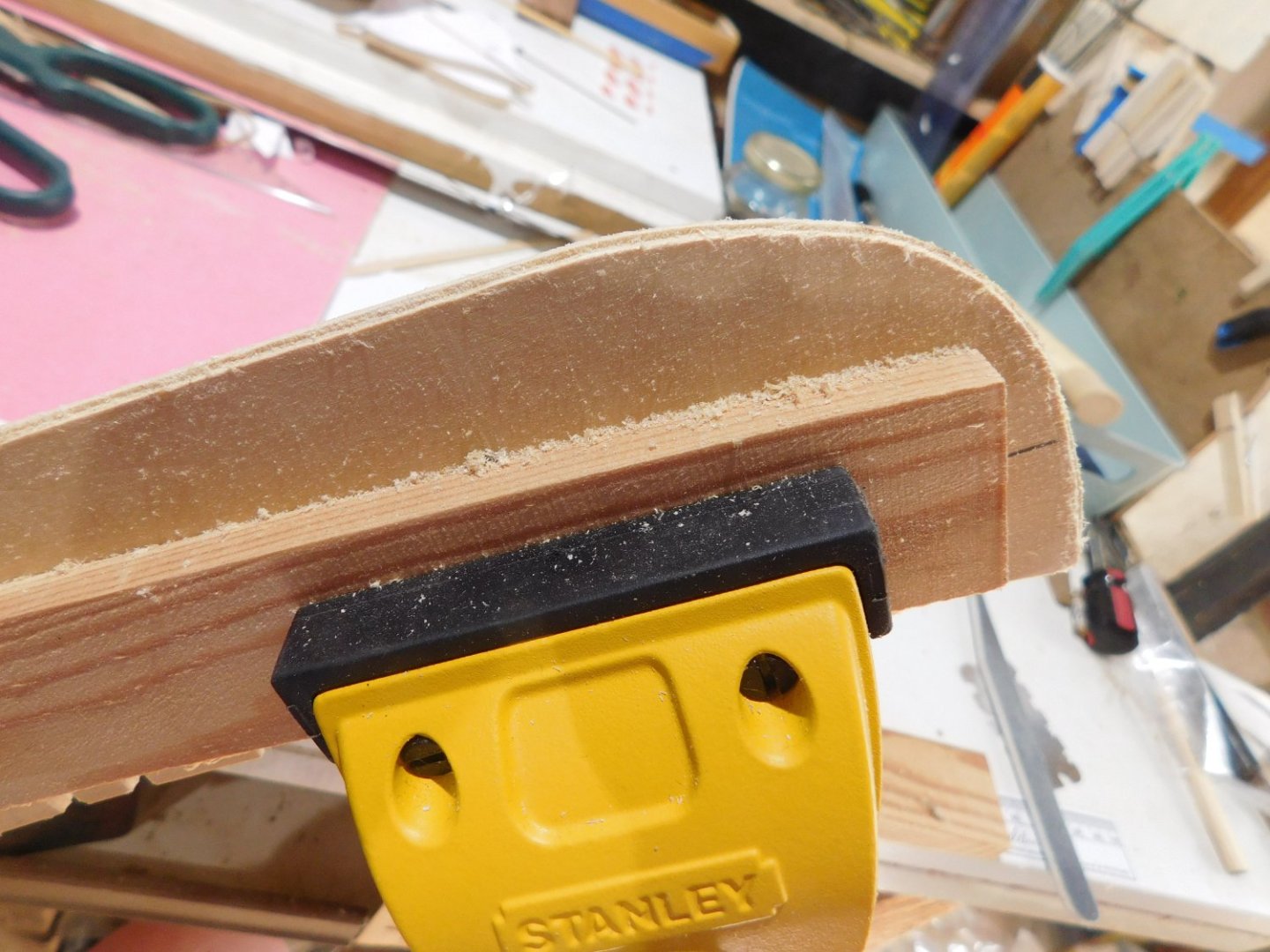
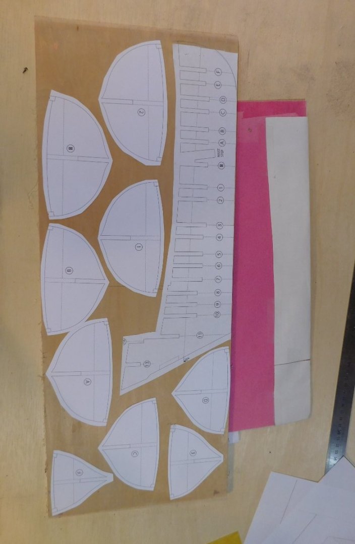
It is time to start again. I looked closely and dispassionately at the hull assembly of Mediator and the quality and accuracy I wanted just weren’t present. The bulk of the problems are down to my choices of materials, such as old cheap ply frames crumbling when fairing was attempted. So, it was time to start over. Let’s call it Mediator 2.0. Using good quality 5mm birch ply I made all new frame sections and formers. The process was basically identical to the first attempt so I will skim through the bulk of the steps and highlight the few differences. The main hull former was, as before, made on the bandsaw by using an A4 plan stuck to the plywood with good quality spray temporary adhesive. I did the aft section first and due to the limited throat size of my bandsaw, then flipped it over and used a reversed copy for the fore-part of the former. A light shining through the already cut-out section made alignment easy. The former with all slots cut (except for piece #14, see later) and waterline marked. First difference: I added a rabbet to the main hull former. This is not indicated on the plans (there are no instructions as such) and the small difference in width between the former material and the keel-pieces did give a lip that may have been adequate for much of the planking, but I feel the addition of a ‘proper’ rabbet can only help. The rabbet lines up with the bottom of the dry-fitted frame. This was the first time I had used the Stanley swiveling vice properly and it was very useful, glad I got it (thanks to another user on MSW). The scraping tool is an Artisania Latina scraper, did a first rate job. First passes were with the 3.5mm x 5mm profile then I carried on with the 5.5 x 5mm profile for another mm or so. The previously made stempiece and forward area of the keel piece were fettled before the frames/bulkheads go in place.
- 43 replies
-
- 6
-
-
- mediator
- first build
- (and 1 more)
-
Guy, glad to hear of the progress and glad to have you back aboard. The plans are pretty good, but I have a suggestion or two which will be in upcoming posts. Nothing big or sinister, just a couple of things that may be worth considering. Hello Pat, thanks for the encouragement. Re-reading my earlier posts, I did moan a lot, forgot to say I was enjoying it. Lessons have been learned, it's time for an update ... watch this spot!
- 43 replies
-
- 2
-
-
- mediator
- first build
- (and 1 more)