tlevine
-
Posts
2,033 -
Joined
-
Last visited
Content Type
Profiles
Forums
Gallery
Events
Everything posted by tlevine
-
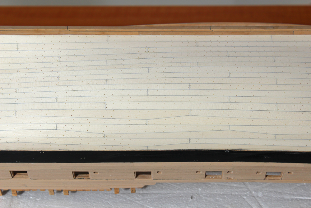
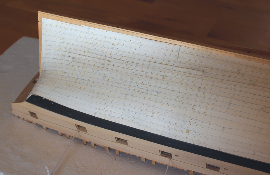
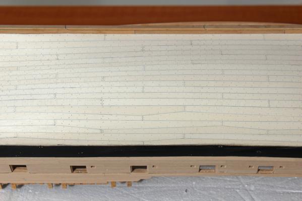
 I have decided to use a finish that will not yellow the holly. In TFFM David mentions a solvent-based sealer for his finish. For those of you who own his Comet book or have seen the photos, that is the look I am trying to achieve. The bottle of solvent-based sanding sealer I have was quite a few years old so I purchased some from Midwest Models, as well as a bottle of flat finish. I have not decided whether to stick with just the sealer or put a coat of finish on as well. The pictures are taken after two coats of sealer, the first sanded down to 320 grit and the second sanded to 400. Later this week I will test applying a coat of the finish on some scrap wood. One of the nice things about the sealer is that the drying time is very fast but as this is solvent based the smell is pretty strong. Unlike a oil based finish, the odor dissipates quickly.
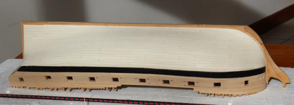


-
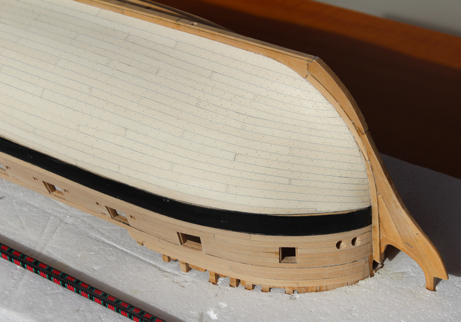
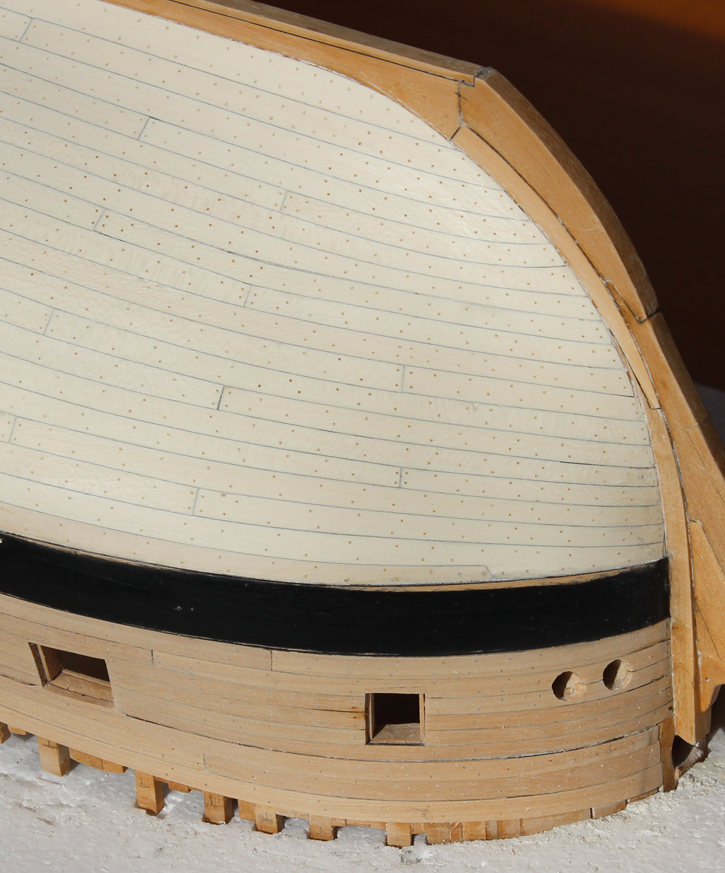
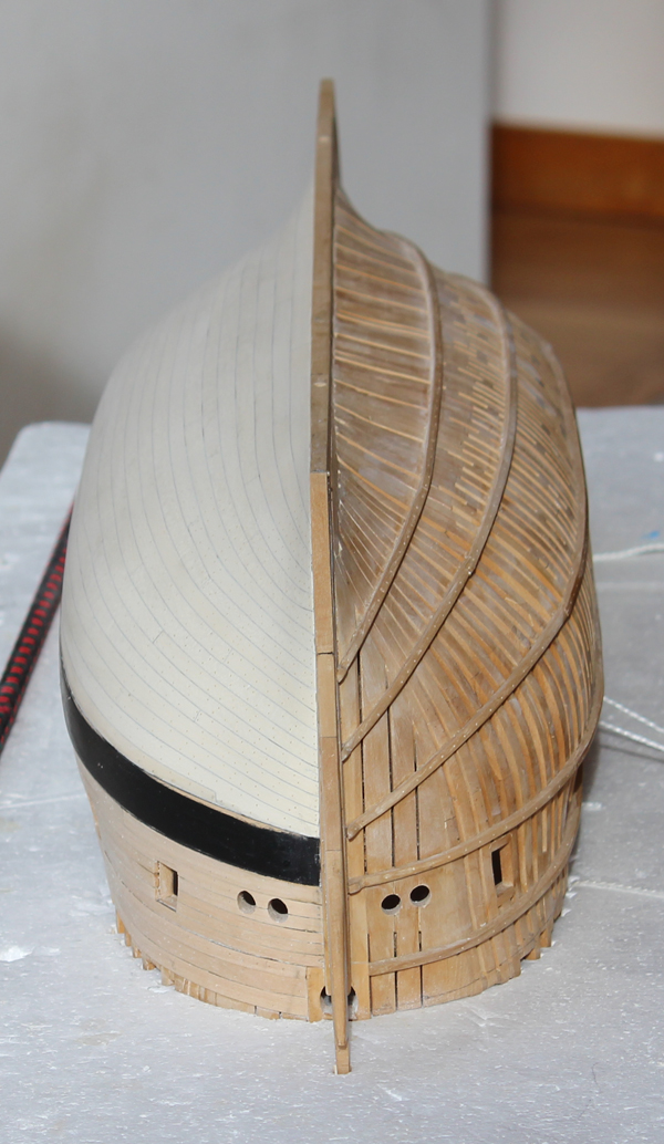
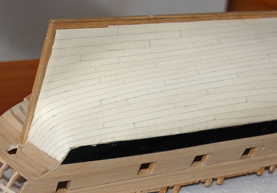
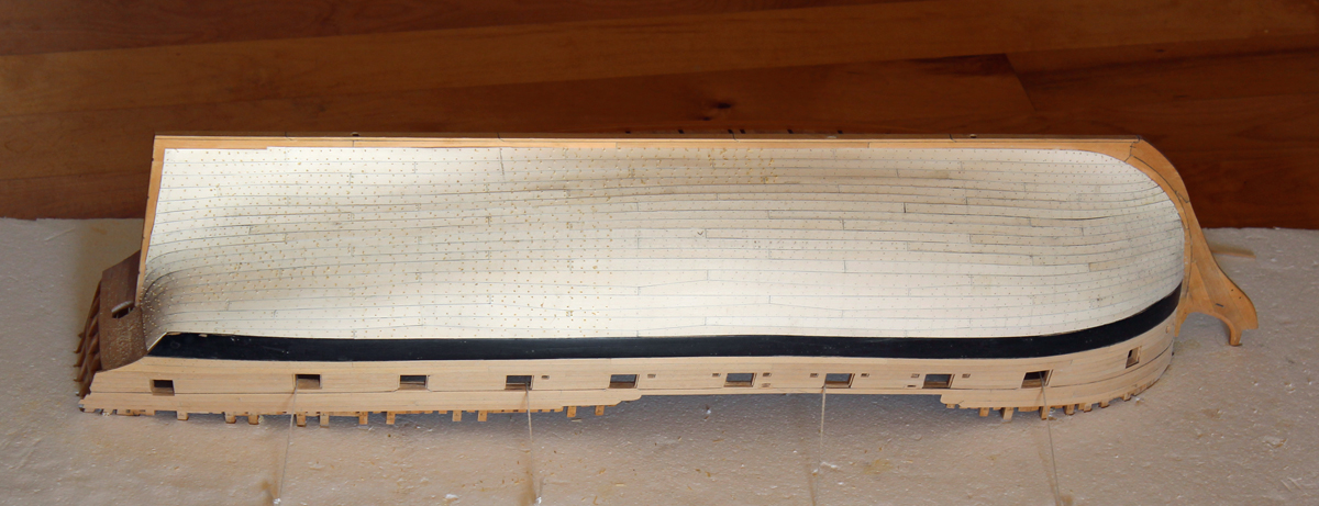
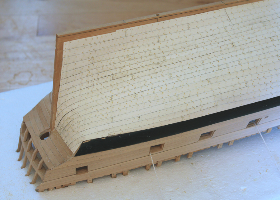
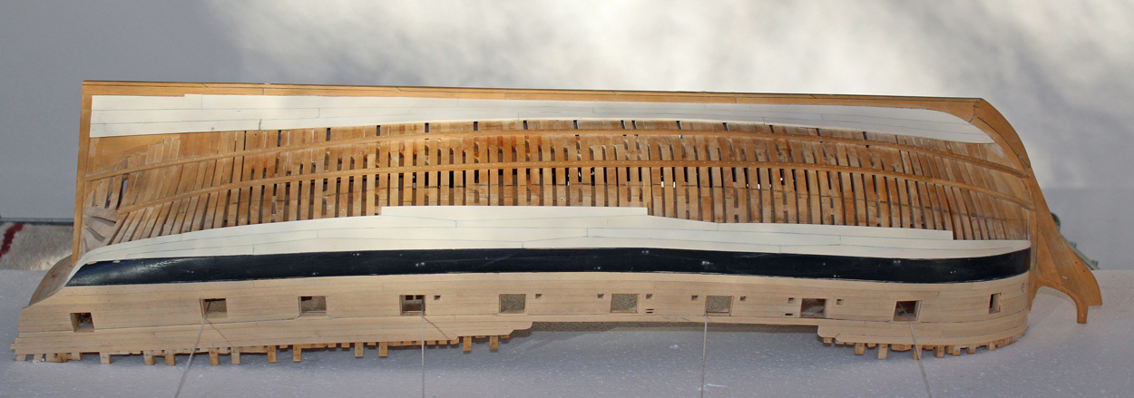
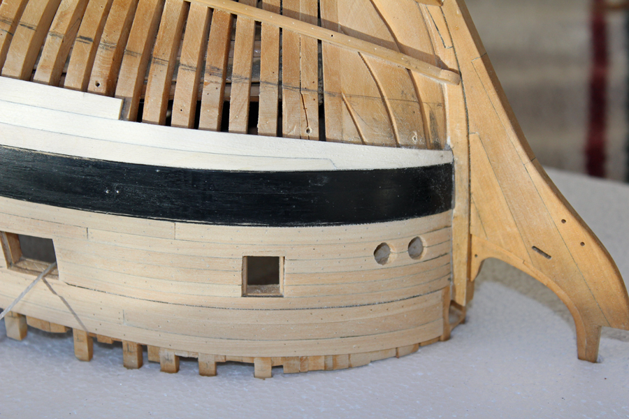
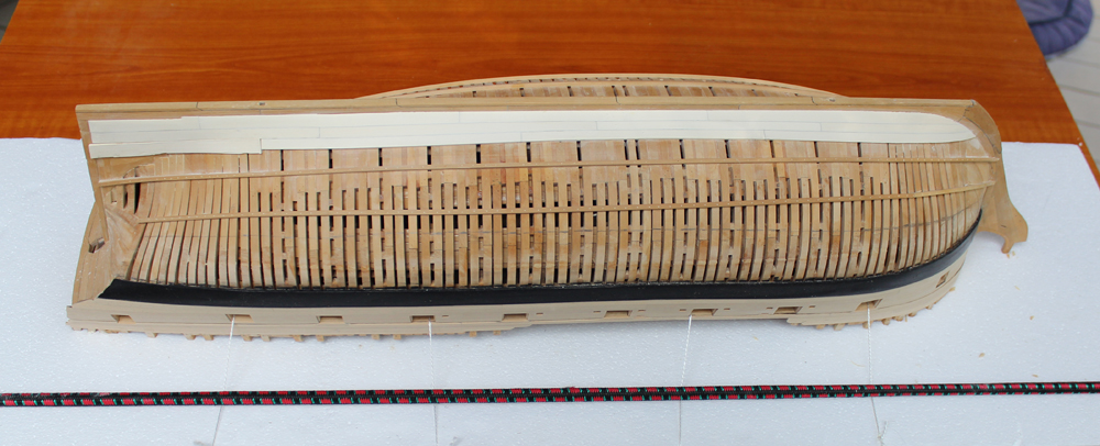
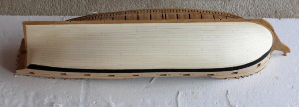
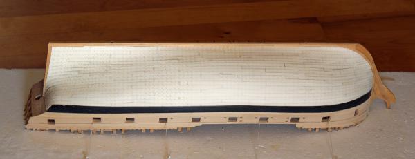
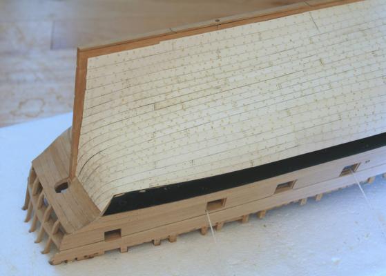
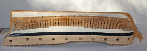
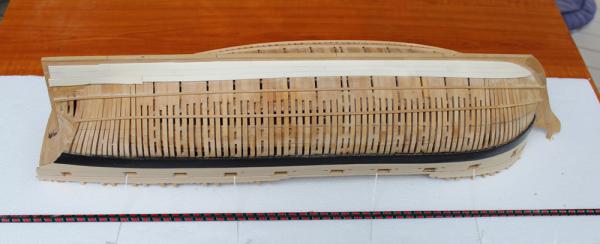
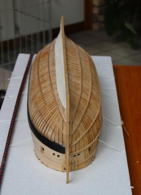
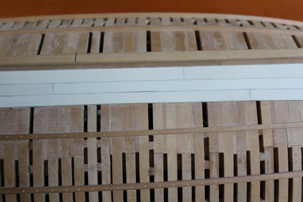
Thanks, everyone for the comments and the likes. I have finished the treenails. I estimate that the whole process consumed about 25 hours of my life. So my ugly duckling is now in the process of becoming a swan (class). Sorry, couldn't help it. I removed the hull from the board for the sanding process. I find it easier to sand a curved object while holding it in my lap. This gives me easier access to the various rabbets and the intersection with the wing transom. In the process, despite using masking tape, the main wale has gotten fairly scuffed up and will require another coat of paint. In the pictures the hull has been sanded down with 100 grit. The treenails are hard to see because no finish has been applied yet.


-
Medic, welcome aboard!
-
Beautiful construction. Thank you for demonstrating the process.
- 662 replies
-
- 1
-

-
- bonhomme richard
- frigate
- (and 1 more)
-
Medic, I have a few suggestions for you. First, become a regular member of the Nautical Research Guild. http://www.thenrg.org/join-the-nrg.php A subscription to The Nautical Research Journal is included as part of the membership. The NRG also sells CDs of the Journal going back to Volume One. http://www.thenrg.org/the-nrg-store.php#!/The-Nautical-Research-Journal-On-CD/c/2719574/offset=0&sort=normal Over the years there have not been many magazines devoted to our hobby. Let's face it, there are at least 20 model railroaders for every one of us. In the US, the only other ship modeling magazine not directed at the RC crowd is Ships in Scale. But they have CD's of back issues available for purchase. If I am not mistaken, they also sell CD's of Model Ship Builder which went out of business 10+ years ago but was a superb resource for our hobby. Except for the RC ship modelers, ours' is a static hobby (no pun intended) so reading journal articles that are 10, 20 or even 50 years old is still relevant.
-
Druxey, it was either plucked poultry or measles. I went with the less contagious analogy. Dave, if I did that sequence I would be admitted to the asylum post haste! And don't forget adding a scratch block in there as well. John, thanks for looking in. Since the posting I got a little more accomplished. Only 25% more to go.
-
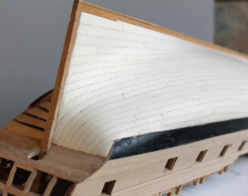
I am not sure which is more tedious, treenailing a hull or tying ratlines. At this point I am over halfway done with an estimated time so far of 15 hours. This includes marking the locations for the treenails, drilling the holes (#75 bit), drawing the treenails (hole 20 on the Byrnes drawplate) and finally inserting the treenails. I have used bamboo for these to give me the least color contrast with the holly. I usually dry-fit treenails but for extra strength these are all dipped in dilute yellow glue. I hope to finish them up next weekend and then start sanding the hull. Right now it is pretty ugly, covered in lines and holes and little bumps which make it look more like a plucked chicken than a ship.

-
I see you used the same scientific method I did in determining the pedestal height!
-
Today I laid the final hull plank. No pictures coming for a bit as I have everything lined off for the treenailing to commence and it looks rather messy as a result.
-
Echo by Maury S - FINISHED - Cross-Section
tlevine replied to Maury S's topic in - Build logs for subjects built 1751 - 1800
It just keeps looking better and better. -
Thank you Druxey, Maury and Ben. And thank you everyone for the likes. You're right, Danny. In laying the hull planking, the tendency is to make the planks too wide. This becomes a cumulative error which would result in one or two rows of skinny planks. Hopefully, only a few more weeks to go before the wood worms go to work.
-
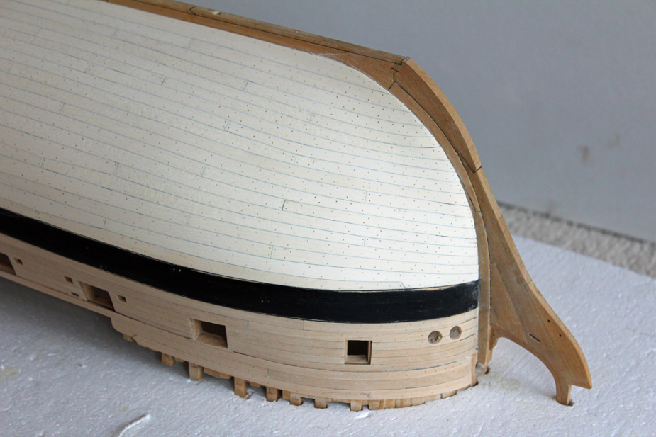
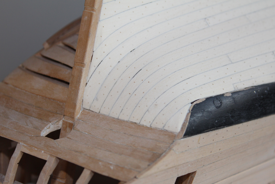
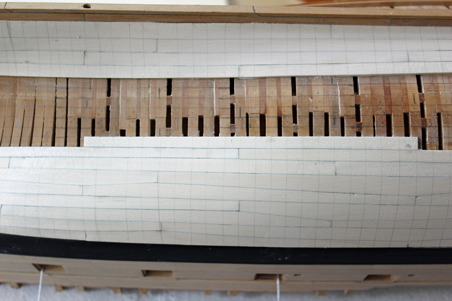
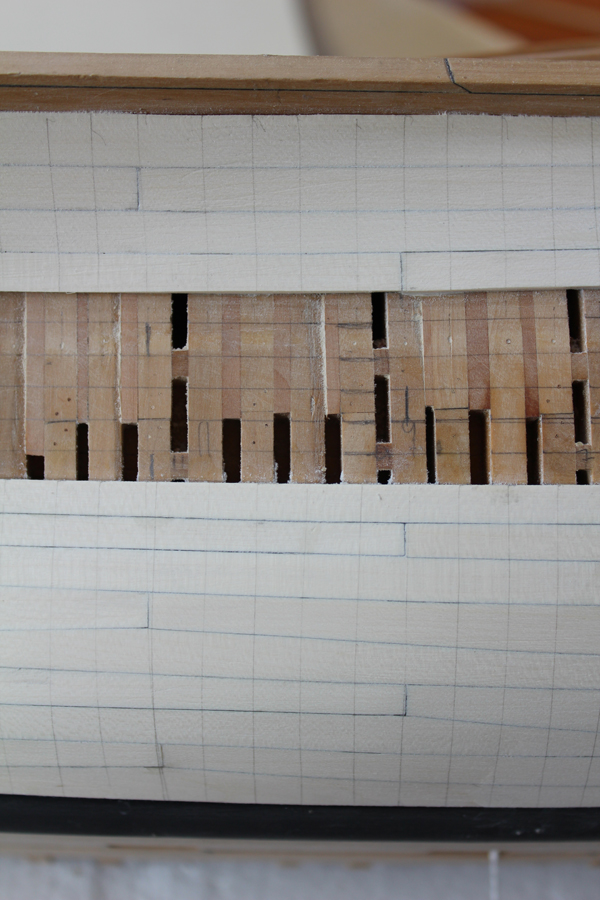
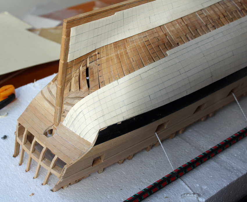
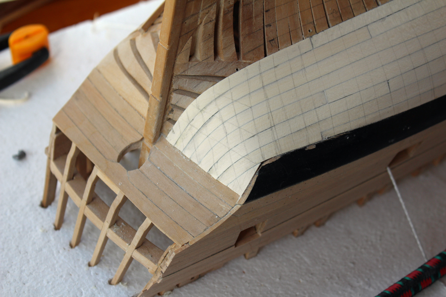
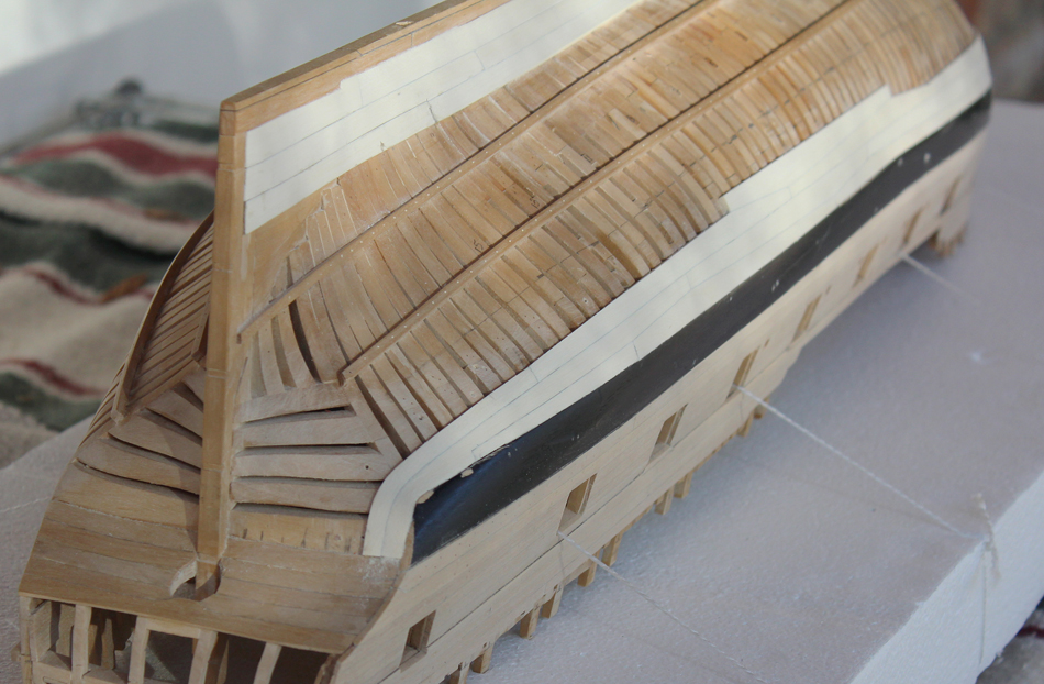
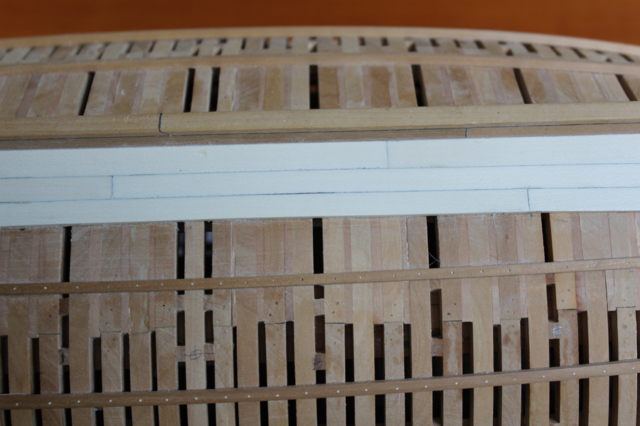
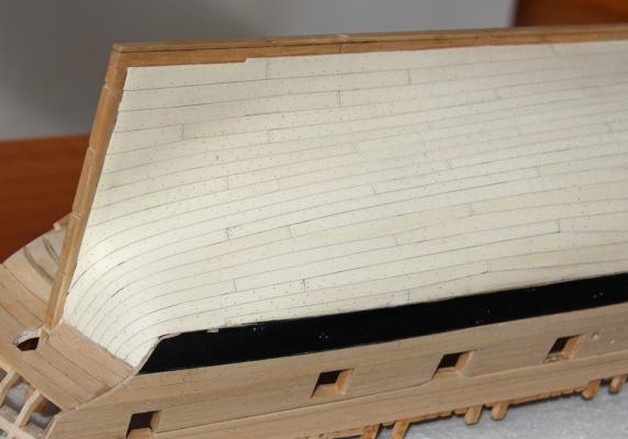
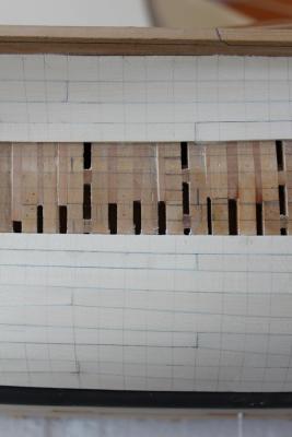
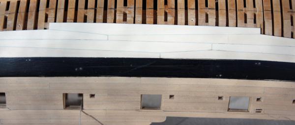
Thanks to everyone for their input regarding the planking below the transom. Obviously, somewhere along the way, a measurement was off by about 1/8" (6" full size). I decided to make up for this by making the planking below the transom look like it was designed to have a filler piece and not a correction for an "oopsie". I am pleased with the look so far. The same number of planks end on the wing transom as shown in TFFM. The difference is that there is no need for a slight flare at the end because of the filler piece. After installing the first row of planking below the "gang of six", I decided to lay out on the hull the rest of the runs of planking. Tick strips were used at every station to obtain the remaining width. This was divided by nine (the remaining number of rows) and the width was transferred to the hull with calipers. After all the station marks were drawn in, the marks were connected in a fair line to show the run of the planking. I also marked out the butts of the planks. This makes the rest of the job much easier. While there was a significant amount of framing visible, I decided to mark their locations on the planking so the lines of treenails would be fair. At the stern this involved also marking out the fashion pieces and the location of imaginary cant frames going up towards the wing transom. Everything looks a little rough at this stage, having only lightly sanded with 100 grit.


-
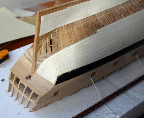
Ed, thanks for clarifying. The most inferior row of lower counter planking extends to the margin line of the wing transom, so the bottom planking ends below that point. The black paint (and marginal photography) does obscure some detail. The other thing is that I have left the aft end of the wale long until I am happy with how things look. I do draw the line at replanking the wale! It may not end up perfect but it will look ship-shape. Good to see you posting again David. Juergen, I am happy Ben alerted us that it has been found. It is interesting to see what items are shown and which are omitted. For example, the only scupper shown is the large one for pump discharge. I was looking at a contemporary model of Atalanta in the NMM collection and noticed that the friezes have a red background, not the blue I had expected to see. How common was this color palette? I certainly want to be true to the original ship but I find the red to be cheap looking and ugly. Any direction would be helpful.
-
I may be misinterpreting what you are saying, and if so feel free to correct me. The horizontal planking on the counter does go down to the wing transom. I went back to the plans as well as to some photos of other Swan class models. In a lot of ships the lower edge of the main wale is close to or at the same elevation at the inferior edge of the wing transom. And in fact, Hahn's model of Kingfisher is built just this way. On Atalanta, the inferior edge of the wing transom bisects the main wale so there is going to be some moderate bending of the plank as it comes up the stern. This is seen in the contemporary model of Atalanta at the NMM. In that model it appears that the filler has been painted black to simulate the upwards sweep of the main wale. I am including a link to the model. http://collections.rmg.co.uk/mediaLib/317/media-317109/large.jpg I have just installed a new plank (pictures this weekend) and with a filler piece there is only a gentle bend required.
-
I think they look fantastic. And with the naked eye they probably look even better, subtly blending into the background. I'll take your "affright" any day of the week!
- 1,215 replies
-
- 1
-
-
- sloop
- kingfisher
- (and 1 more)
-
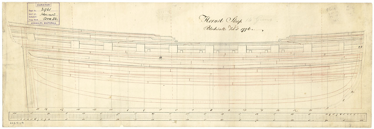
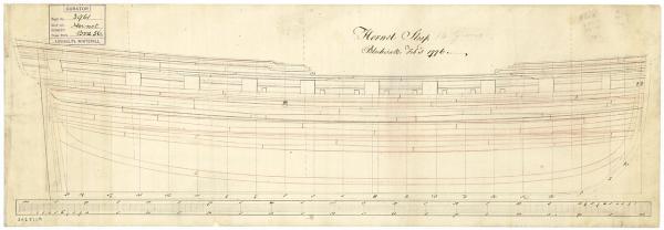
Tom, you'll see the filler piece in a few days. I have attached the Hornet planking scheme from the NMM. It is plan ZAZ5119.
-
Hi Ben. Funny thing about the tuck of the stern... It's wrong. Druxey was kind enough to point out that there should be a filler piece between the outer wale and the first full plank. This would result in a 45o angle where the counter and the planking meet. So I have debonded all of the planks aft of dead flat, remaking a few planks and hopefully salvaging the rest. Unfortunately, I had already installed five rows of planking, not the three rows seen in the photos. I did not know that the Hornet planking scheme was available. I am using the one from TFFM. For these six rows of planking, all you need are three measurements, the fore and aft width and the width at the widest spot. One side is essentially straight and the other is two straight lines intersecting at the widest point.
-
Thank you, Druxey. Maury, I wasn't too sure about the holly at the beginning. I was afraid it would be too stark a contrast. But now that there are a few strakes in place I really like the look. The finish will also tone down the "whiteness". Its handling characteristic is what I am surprised about. It bends very nicely and keeps a good edge.
-
Not much to show for the last few weeks. Last week was devoted to the NRG meeting. It was great to put faces to some new names. Hope to see you again next year in Mystic. I started the planking below the wales. The first 6 rows of planking are anchor stock and the rest is standard planking. The first strake is 3" thick at the wale, tapering down to 2". The rest of the strakes are 2" thick. I laid the first row of strakes full thickness and then tapered the lower edge after the second row of planking was completed. The extreme fore and aft planks are dropped. I marked out the landing spots for the planks terminating at the counter to prevent any uneven plank widths. Holly is a pleasure to work with for the hull planking. Gentle curves can bent by hand. The extreme bends require a 30 minute soak in water and are pinned in place with clamps and planking screws. After they are completely dry, final shaping is done and the plank is glued in place with almost no pressure. I like to rough sand the planks every few rows to check for any problems. It is a lot easier to pop one or two problem planks now rather than several planks after the hull is completed. The wale has gotten scuffed with handling and sanding. It will get a re-paint after all the planking has been installed.


-
I received my autographed copy of Comet this weekend at the NRG show and have made it through the first few chapters. As one would expect, the book is well written with numerous sketches and full-color photos of the completed hull. There are six sheets of plans which include all of the frames fully lofted. A great addition for anyone interested in 18th and early 19th century military ships.
-
The NRG annual Conference in St Louis 2014.
tlevine replied to Chuck's topic in NAUTICAL RESEARCH GUILD - News & Information
I'll be at the registration desk Thursday evening. See you all at the bar. -
I went back to the build log and found the following: May 23, 2012. I have finished the filling pieces. I used Swiss pear to give a little contrast with the boxwood. In contrast to the pear that Danny is using in his Vulture build, this is less pink. Maybe it is the age of the wood; these billets are 25 years old. I initially installed port and starboard pieces simultaneously to prevent warping of the keel (thank you Danny for that lesson!) but once everything felt solid, I removed the hull from the building board and added them where ever they would fit. I deliberately left out the filling pieces on the frames that had spacers for aesthetics and to allow a little light to enter the lower hull. The pictures show them roughly faired in. They will be finished after the gunports are completed. There's your answer Ben. Don't mind the hijacking at all. We all learn from it and isn't that the point of MSW?
-
Maury, I got the table at Hobby Lobby. They always have 30-40% off coupons on line. Ben, I did not insert floor filler timbers where there were spacers (every fourth half-frame). I honestly don't remember why I did it this way, it was so long ago.
-
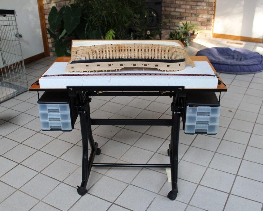
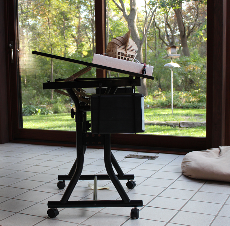
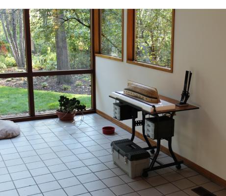
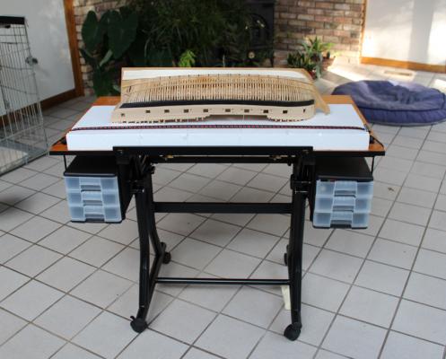
Thanks for following this build, Christian. Not much got done this weekend, between Fall cleanup and getting my Hannah cleaned up to take to the NRG meeting next week, there was not much time for building. When I bought the styrofoam for the base, I found a hobby-quality drafting table. It elevates and tilts, important to me since I prefer to work standing up (I guess it's the surgeon in me). And at 30% off, what girl could say "no"? A bungee cord across the base keeps everything in place, even at an angle. And the casters allow me to follow the sun. The second two rows of planking are almost completed. When I return, I will start the planking below the wales.

-
Looking good. The rabbet is no more difficult than the aft deadwood. Mark it out first and then take your time. If you find yourself getting hurried then stop and come back later. I start my rabbets with an 11 blade that the tip has been broken off of and either a steel ruler for the straight sections or a french (or ship's) curve for the stem. You can grind the angle for the rabbet into a straight-edge razor blade and use that as a scraper to deepen the rabbet and avoid oopsies.
- 969 replies
-
- 6
-
-
- hahn
- oliver cromwell
- (and 1 more)