


garyshipwright
-
Posts
916 -
Joined
-
Last visited
Content Type
Profiles
Forums
Gallery
Events
Posts posted by garyshipwright
-
-
-
-
-
-
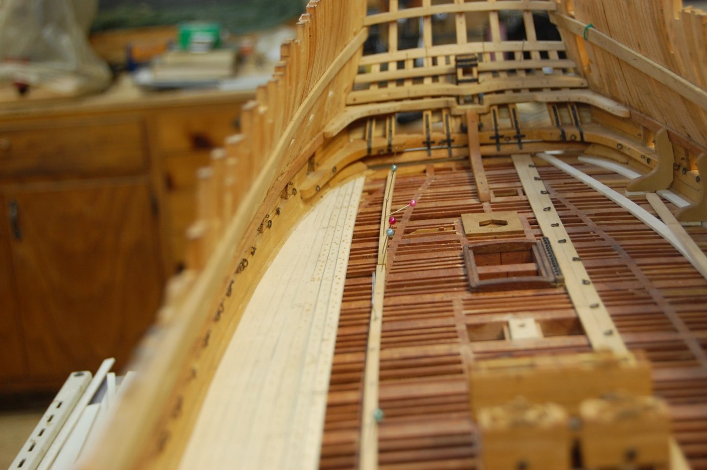
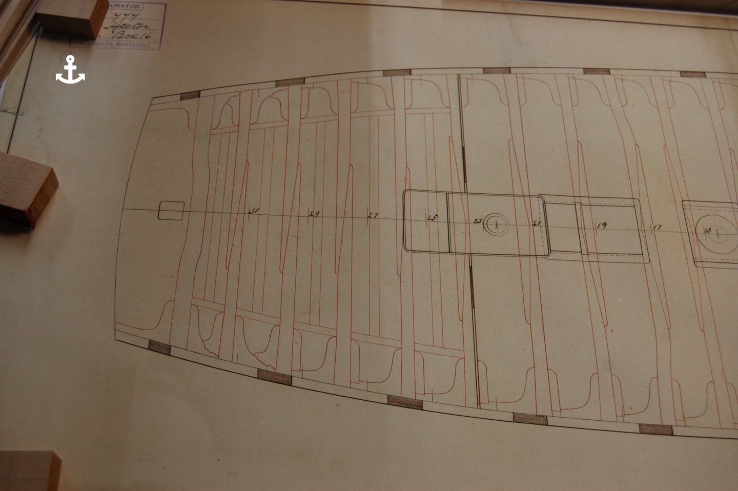
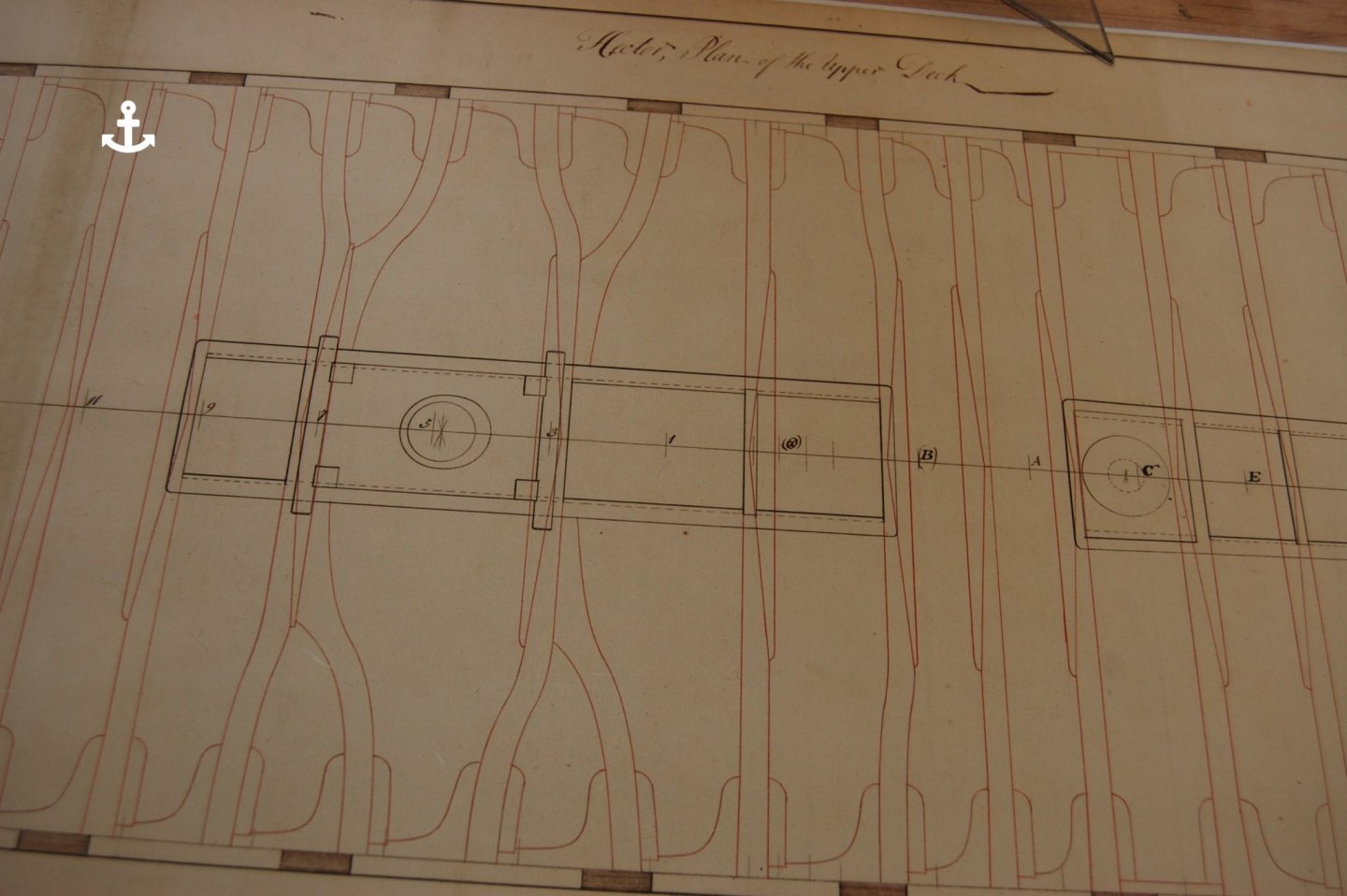
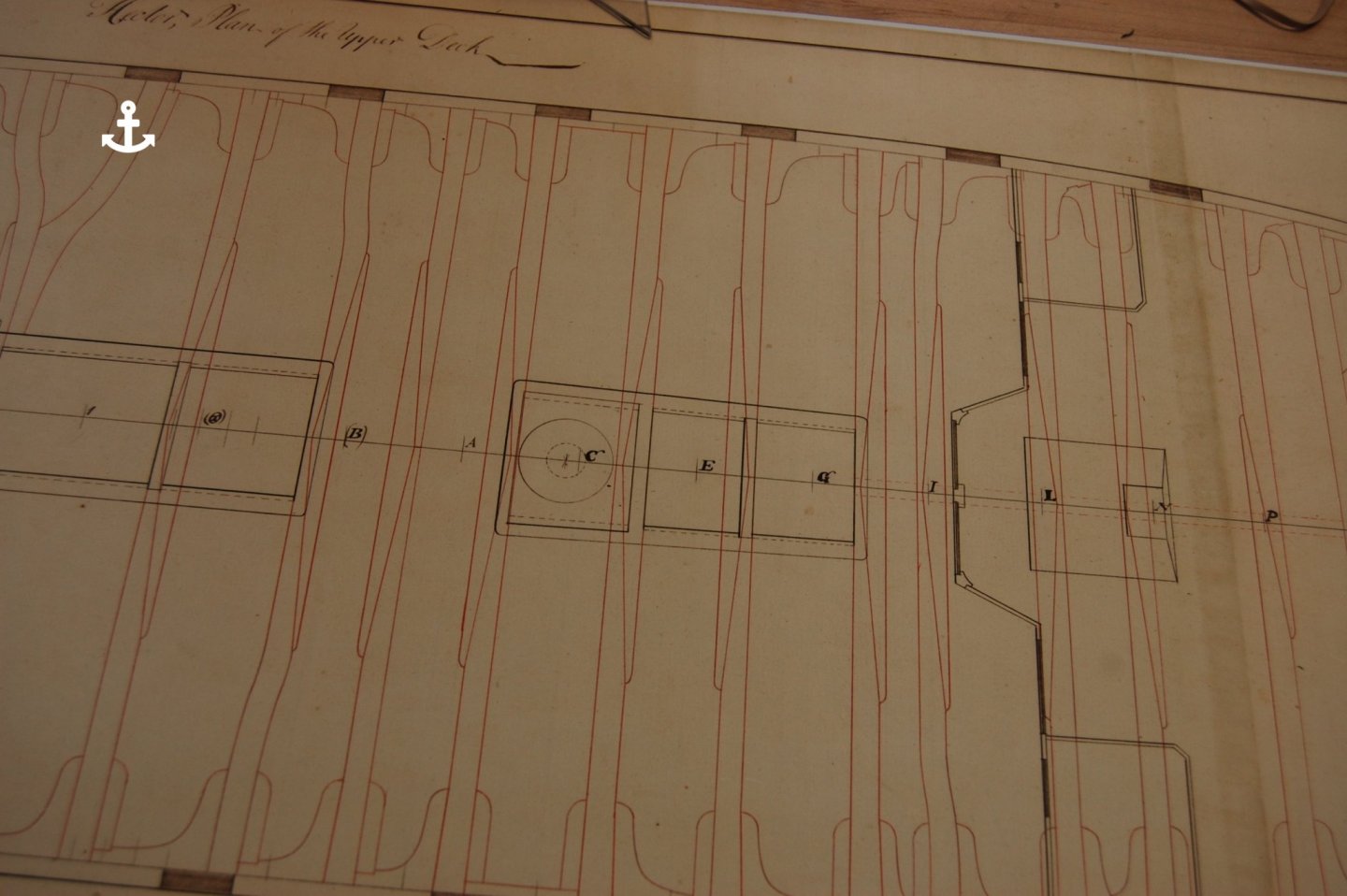
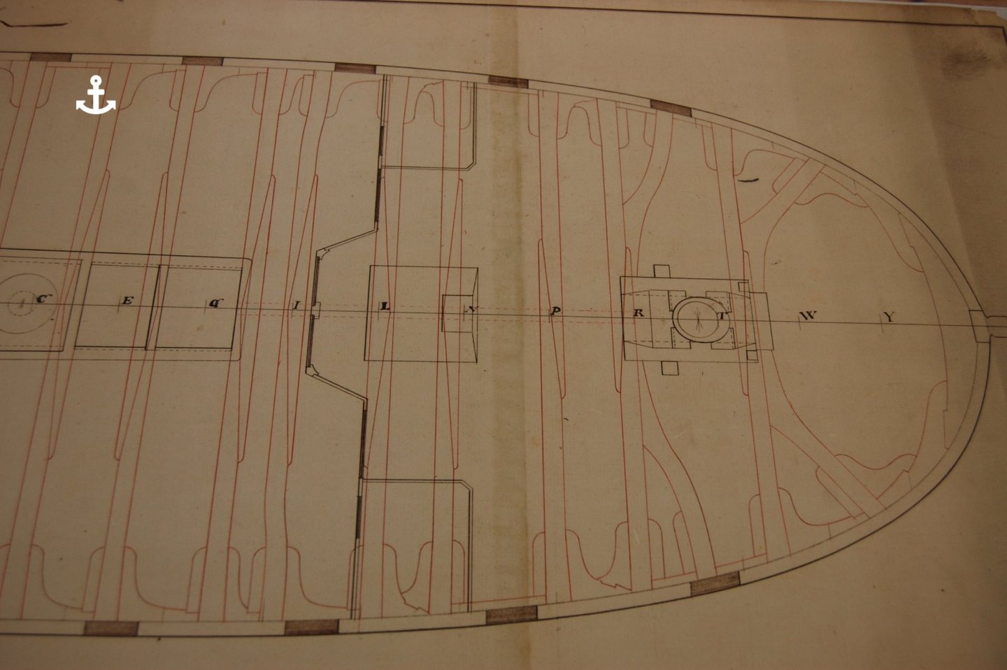
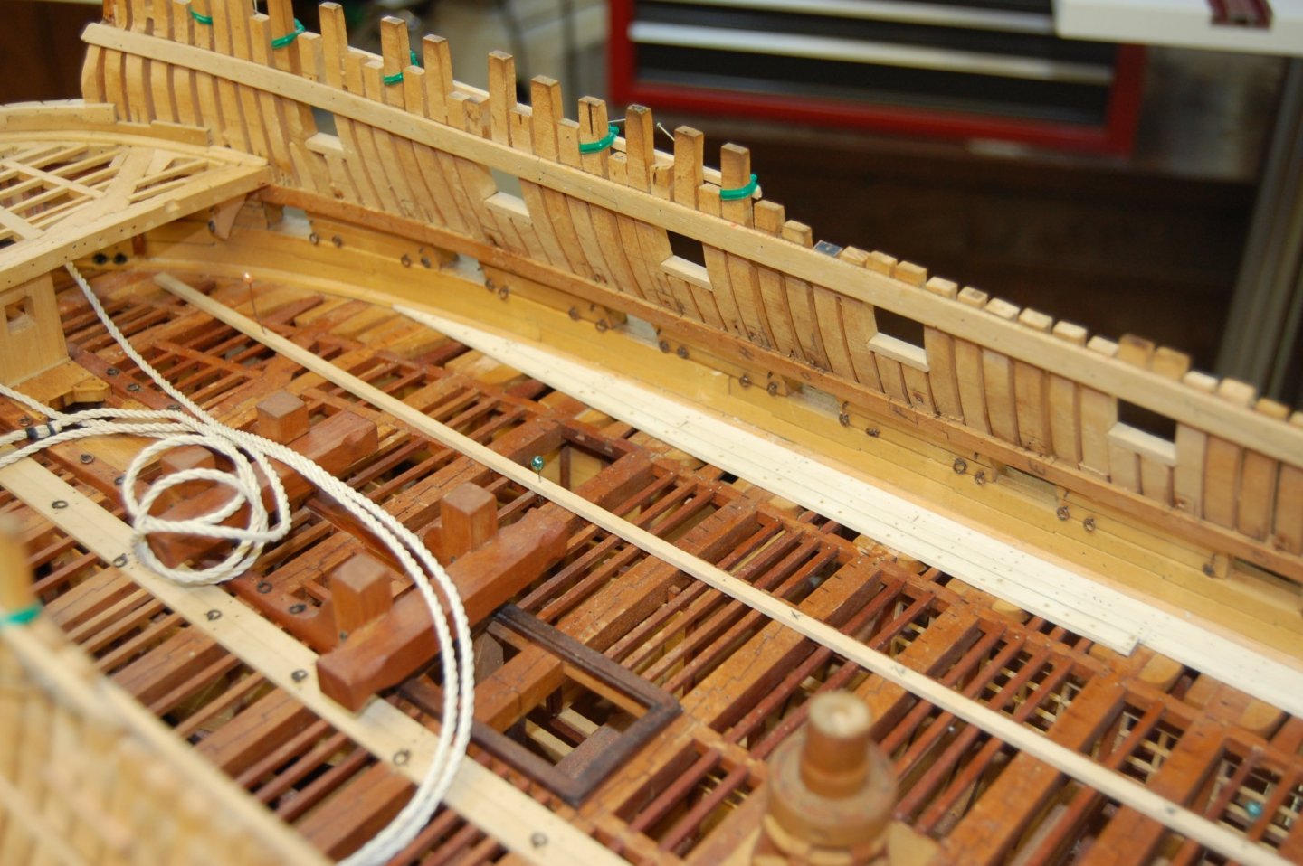
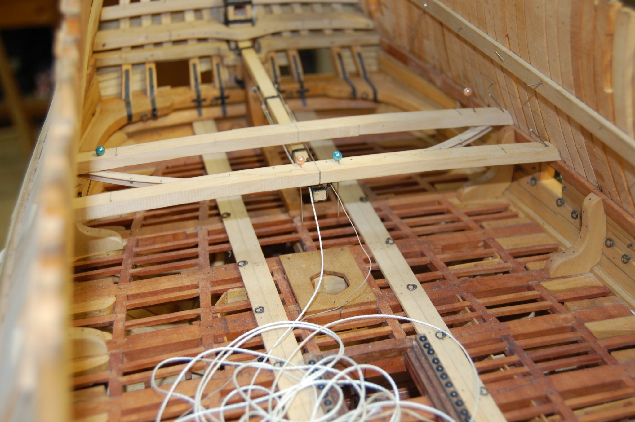
Hi Mark. After looking at your knees lay out at the last couple of beams of the upper deck I found out that fitting hanging knees in the last 3 or 4 beams that it was not possible for me and it was because of the knees that fit the helm port and wing transom. They are big knees which stuck out from the side, and would have may it just a little on the hard side fitting hanging knee's. It made of been the way I fitted them but can think of no other reason why Hector plan show's them that way. When you look at the plan of the Hector you will noticed that they used double lodging knees between the last few beams because of those transom, at least that is what comes to mind. Here is a photo of those knee's on Alfred that show those knee's. Any way it does give you some thing to think about when you get to this point. I looked in your log for those knee's on Bellona but doesn't look like you have added them yet. Just some hind sight for you. Gary
-
Hi Mark. I just checked some of the contracts I have and the one in 1755 gives the Hanging knee arm against the beam as 3 feet 7 inches long and the Lodging knee arm against the beam as 4 feet long. The contract of 1763 says the same thing accept the hanging knee arm is a inch shorter. They also say that the lower end of the hanging knee has to run down at least 6 inches past the upper edge of the spirketting. This is what am using as a base line for making mine on Alfred upper deck and doesn't seem to have changed much up to Steel's time and looks like it increased in only a inch or two.
-
Guys being that we are talking about the aft part the Dorsetshire had a different set up of those aft carlings so I take it that those half beams may of been shorter then the one's on Hector being she was built in 1757 right around the time of Bellona? Mark forgive me for talking about this on you log but figure it would be interesting to talk about. Gary
_RMG_J3114.thumb.png.b5e83574fbd3b69fd221f59cdf29f506.png)
-
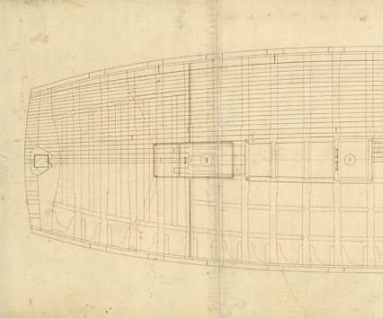
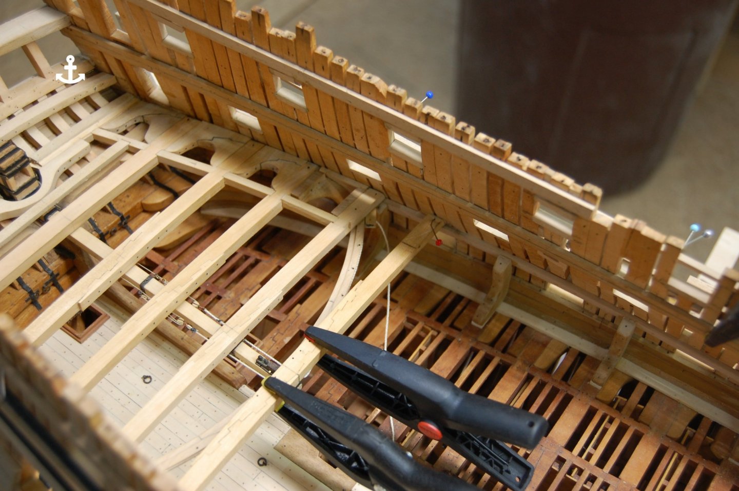
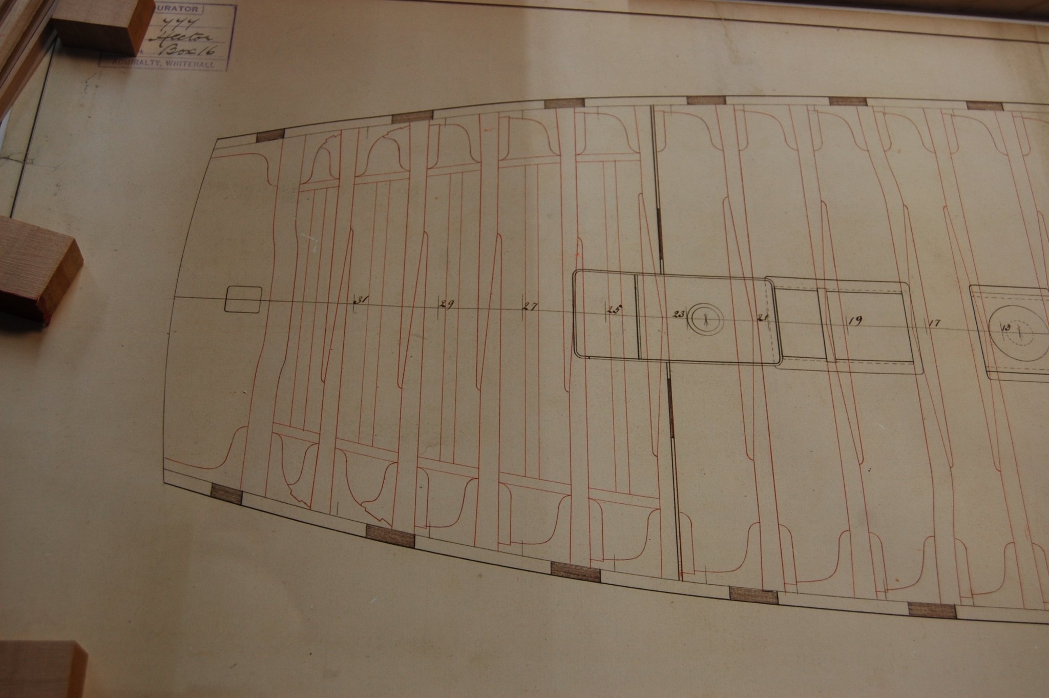
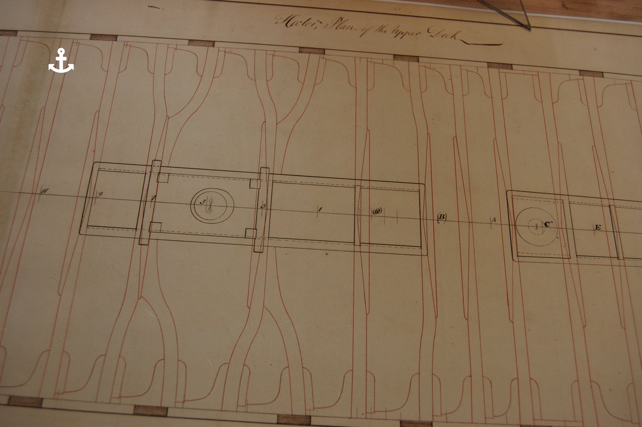
Hi Mark I don't think Siggi is talking about the half beams but the knees at the side being cut off at the ends. I think if Mark moves the carlings in closer to the middle line they would not need to be cut off at the ends. I up load a photo of aft part showing how this was set up. Its for a 74 but not sure which one.Also added one of Hector. Forgive me if you know this which am sure you do🙂 More for others to see what we are talking about then us old timers like my self.

-
-
-
-
-
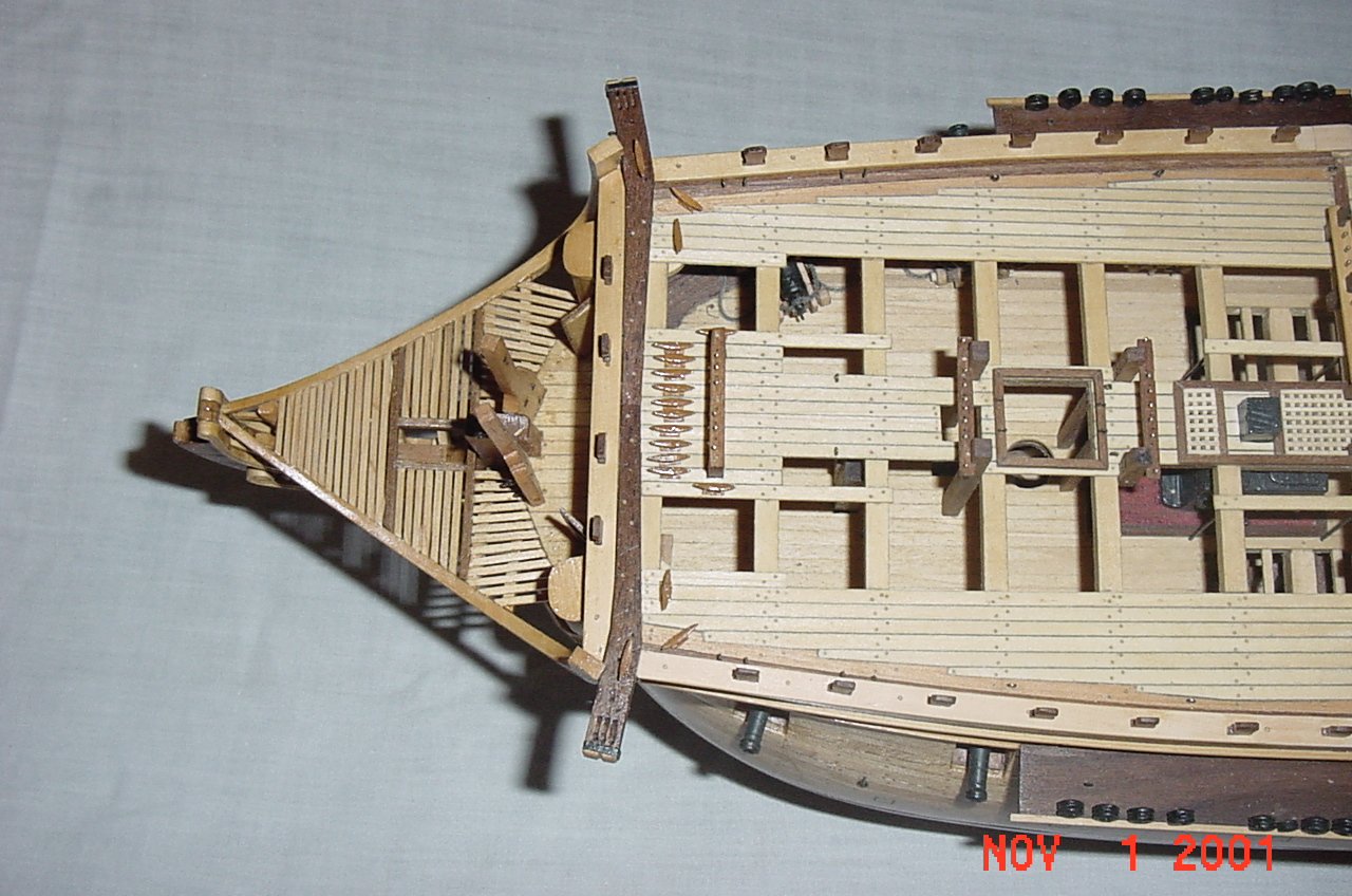
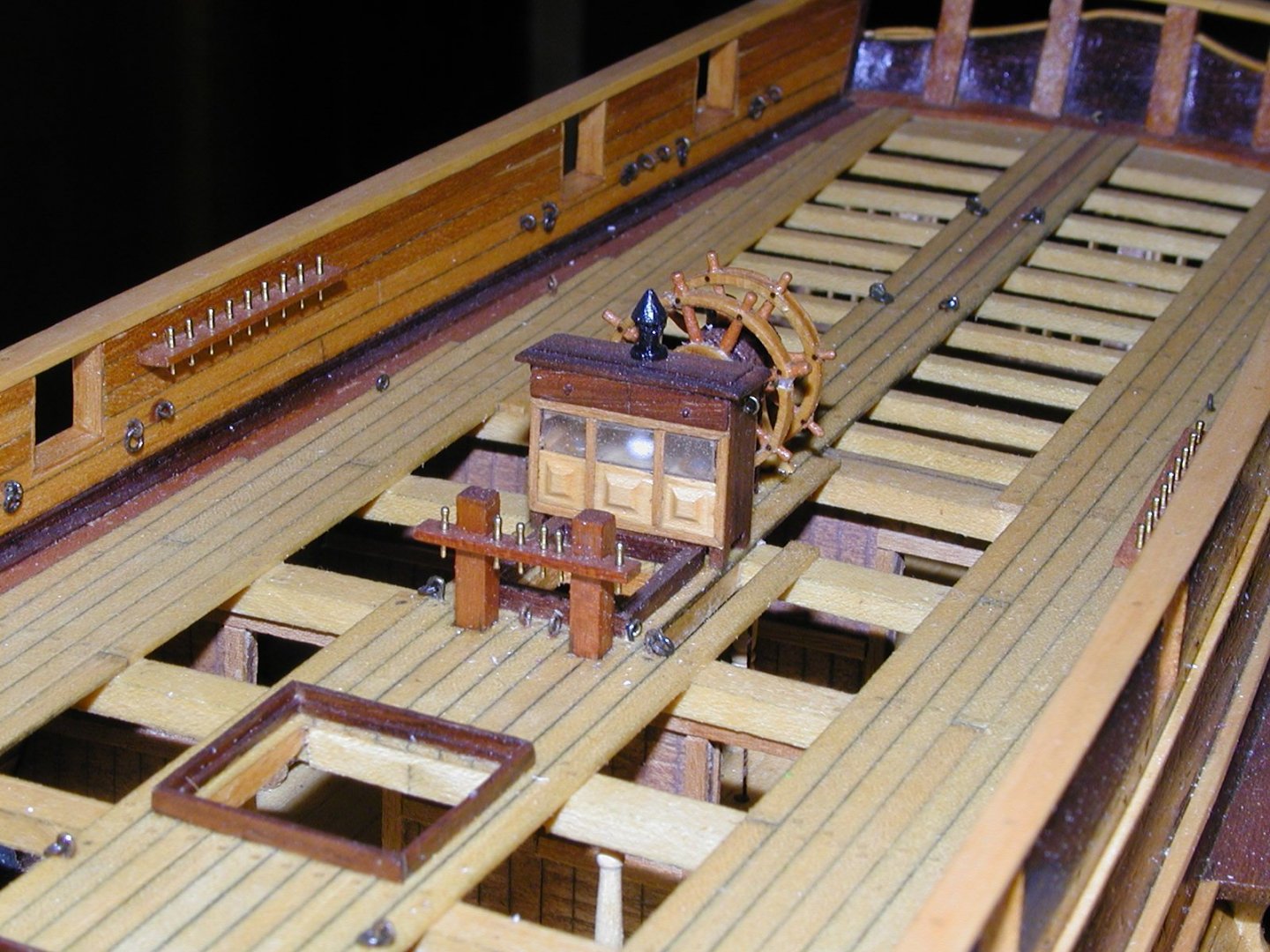
Hi Mark. Am not sure but in the AOS Bellona shows on page 65 that the sweep is set back by one beam compared to what you showing and maybe that is were the goose neck fitted on the back side of the sweep. It shows blocks further forward on the end of the tiller and looks like the tiller rope is going from those blocks, through a eyelet then to a block at the side. Finally going fwd to be guided up to the wheel. How right this is am not really sure. Will see what I come up with. I added a photo of my sweep with the rollers. You just make them out on the far right and far left side with bolts holding the rollers in place. Gary

-
-
5 hours ago, SJSoane said:
Gary, thanks for the note regarding how to handle the tiller ropes. I would have been in some difficulty getting around a central carling a few months down the road. Isn't it great to share ideas on this website!
Mark
Mark being able to exchange information and note's with your self and other's is outstanding and I for one really like sharing what I know to any one who is open to it. Being able to give some thing back is my way of thanking others who have given this to me.
-
Hi Johann. Thank you for the how to post on making those tiny blocks and your work still leaves me on the speechless side. I took a look at the reference you gave on the Atlas du Génie Maritime and think am going to hang on to that one. Do you know off hand if they have published the Atlas in book form since then? Could be a good one to get. Only item I have that comes close to this is the Encyclopedie Methodique Marine, 3 vols set and 1 vol of plates. Thank you. Gary
- Keith Black, mtaylor, archjofo and 1 other
-
 4
4
-
Thanks Alan for the info. . As far as being a beginner at ship modelling have a deep feeling that we are both in the same boat and learn a lot from watching your build log as many others do. Do believe you are far from a beginner good sir and thank you for helping the student. Gary
-
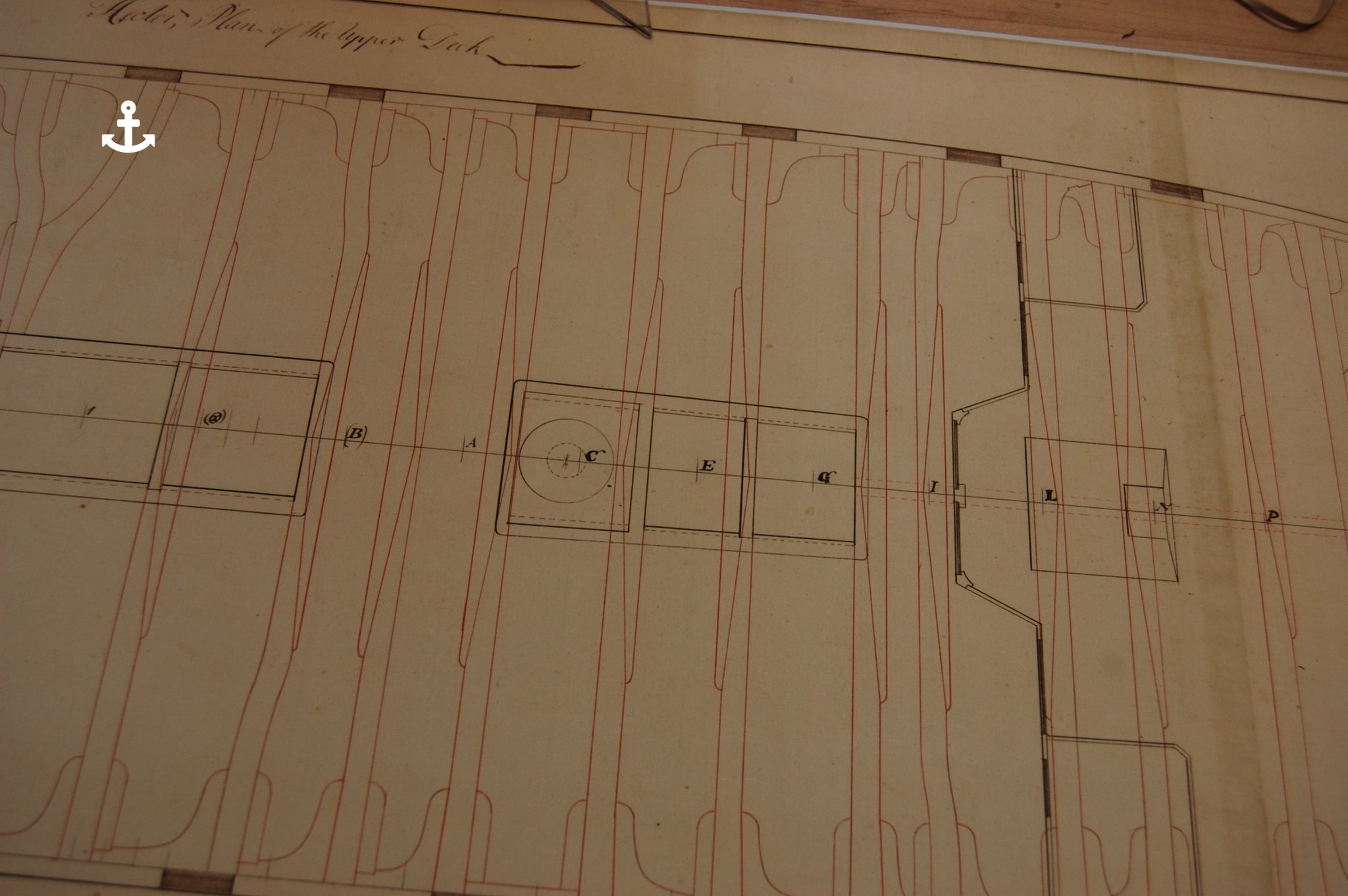
Hi Alan. I noticed that you have three carlings per side from the fore hatch to the second beam aft of the stem and was wondering if this was done in Elephant's time. From what I have read in the contracts I have it would of been something like what Mark shows on his. The contracts I have says that their was only two per side from the fore hatch to the stem. They did have one in the middle from the fore hatch to the back of the fore mast partner with the carling stopping at the aft beam of the mast partner. Believe it was called the furnace/stove carling and was 12 inches wide but don't hold me to the 12 inches. This one was put up underneith those beams and believe it was set in to the beams by 2 inches. They also installed short carling on top of that long carling between the beams and filled the space above that carling. If elephant was different would love to know how they did it during her time frame. You can see that carling in dashed line running below the beams in the 6th photo in the Hector plan above. You probably already know this so forgive me if you do. Thank you sir. Gary
-
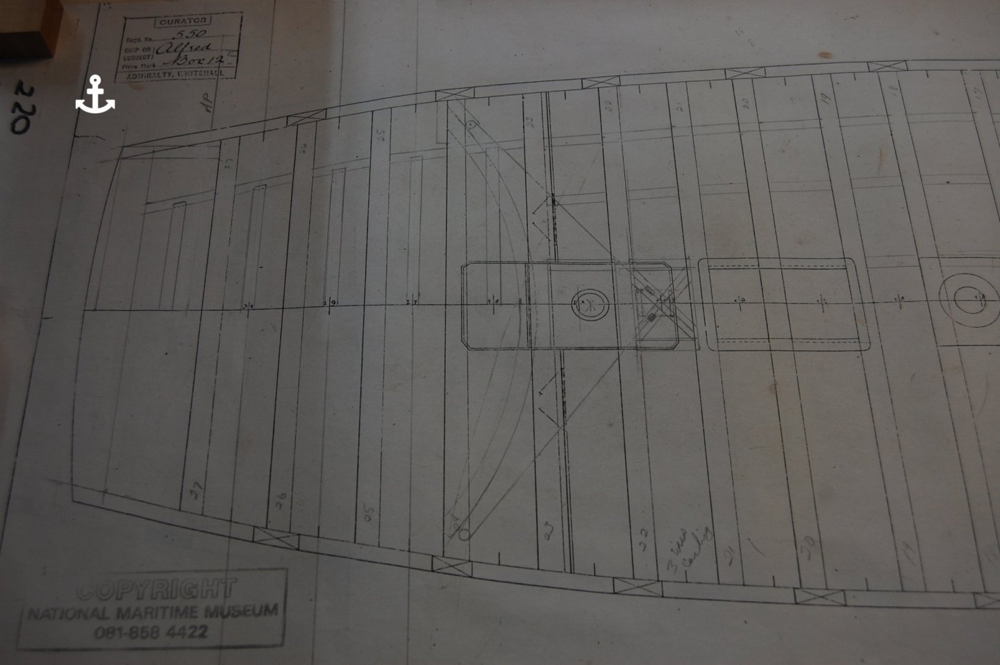
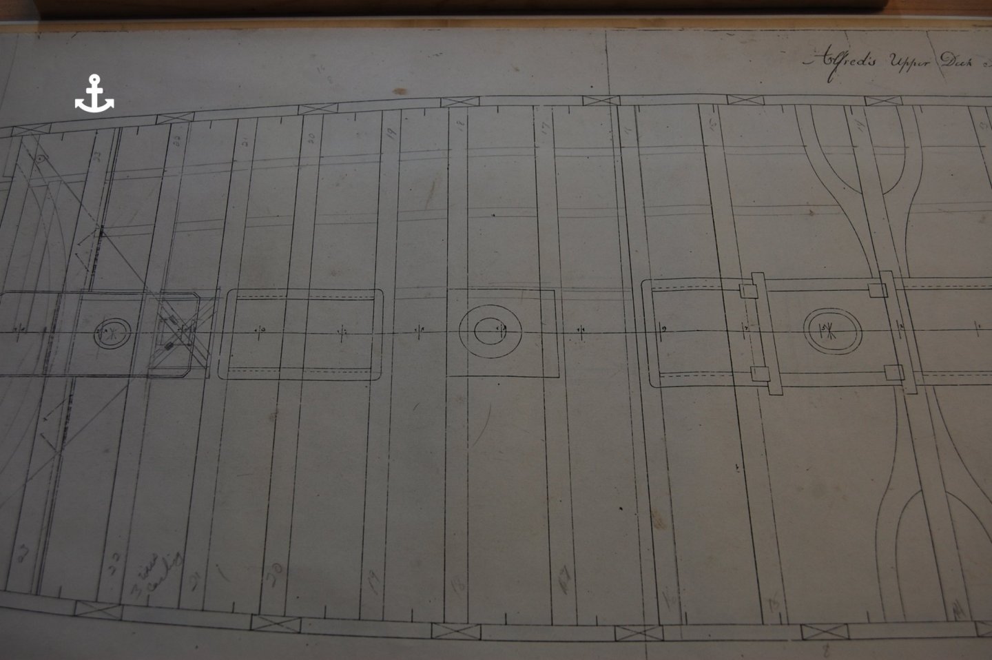
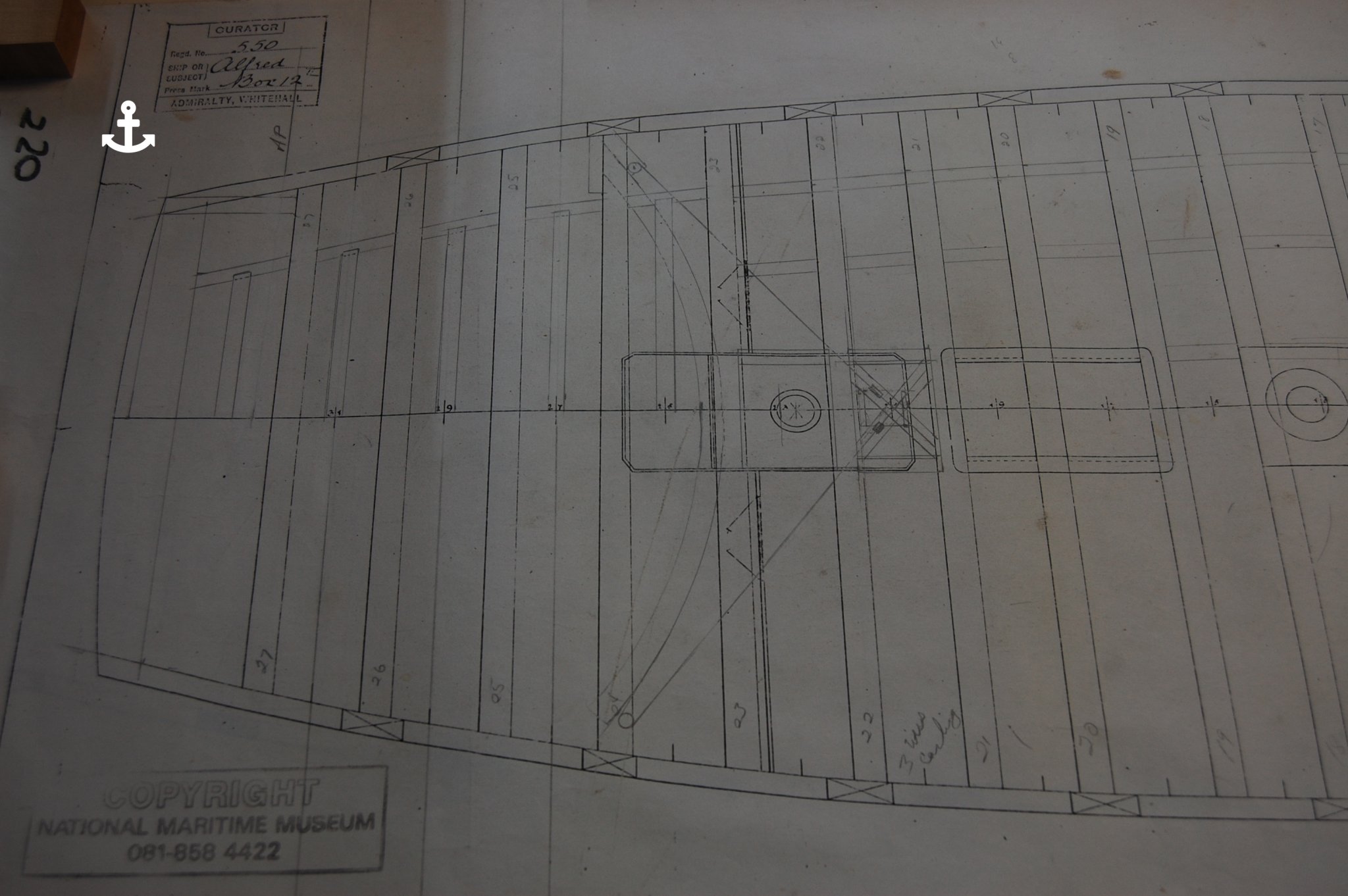
Hi Guys do you mind if I crash the party. What you have put on the log just goes to show us that the decks were all done just a bit different and like your's self's it really hard to figure them out. On Alfred it shows that she has one center deck beam with two arms per side but the two most forward beams have the same as what you show for your deck's. Now coming up with hanging and lodging kness, now that is were the real fun starts. Am using Alfred deck plan to lay out the beams but using Hector to fill in the knee's and the way the aft part was laid out. Now on the carling and ledges am using the contract's to figure out how they were laid out. Hoping that maybe am on the right track to how they may of been done. Hay Mark, Alan your plan's of the upper gun deck is out standing but have a question and you may of already address it. Mark the carling you have forward of you mizzen mast may get in the way of the fitting's for the rudder ropes which go up to the ships wheel. When I work Alfred's out I used a x set of carlings with sheaves to guide the ropes up. Of course with out looking back am not sure if this was done the same way. Seems French way of doing this was one piece attach to the beam with two sheaves at different angles I believe. Mark when you said Conway what book are you talking about? You know me I just love books. Thanks guy for letting me in on the party😊Gary
-
-
John according to Peter Goodwin the water way and the margin plank was two different pieces of wood. . The waterway was a strake of specially fashioned plank worked fore and aft along each side of the ship across the ends of the deck beams. The function of the water way was to form a watertight seal between the side of the ship and the deck. If water was able to enter at this vulnerable area of the ships structure both the ends of the beams and the ships timbers to which they were joined would become rotten. It was in the shape of a L as a easy way of looking at it shape. The margin plank ran parallel to the ships side and fayed to the waterway. The function of this was to pre vent the normal straight deck planking from being tapered to a fine angle where it met the curvature of the ship's side at the fore and after ends. The margin plank was thus fashioned to receive the butts of those planks. I added a couple of photo's showing how I did this on my Confederacy and a photo showing the Alfred. John if you put the waterway plank at the bottom underneath the bulwark planking and then butt the margin plank up next to the water way that would be my way of doing it. I am not sure but am thinking that the bulwark planking and the spirketting are the same thing. Hope this helps sir.
- bruce d and Ryland Craze
-
2
-
John could you share a photo or two of you deck? It would be a big help to us to be able to help you? Gary
- mtaylor and Old Collingwood
-
2
-
Hi john this may help you. The drawing came from Model Ship Wright and the author was David White.
.thumb.jpg.99ae0fad138373de0418539f9280b798.jpg)
.thumb.jpg.eb31ae1e6fb484f0525f62079fe0e15a.jpg)
- Ryland Craze and mtaylor
-
2
-
Hum wait till you ask your daughter were your phone is and she tells you your talking on it. I was a bit red face over that one. Well good sir am going to hold you to that part.😊 Gary
- cog, Canute, Keith Black and 6 others
-
9

_RMG_J3114.png.e23f23de7dd76d4871aaf16bf4d2f37c.png)


.jpg.47d07d9a5211c3a0ebccbae84a82b553.jpg)
.jpg.c287a6d92f05ecf54f6a9453897c1eaf.jpg)
HMS Bellona 1760 by SJSoane - Scale 1:64 - English 74-gun - as designed
in - Build logs for subjects built 1751 - 1800
Posted
Mark here is a draught of the Glory of 98 guns showing what I believe is the way her pillars were laid out. On her gun deck and middle deck looks to have all her pillars and seems there is one on each side of the capstain on the fwd side. I know its not a 74 but at the moment its the best I can find. Hope it help's. I also added one of the 64 gun ship Standard. Gary