


garyshipwright
-
Posts
901 -
Joined
-
Last visited
Content Type
Profiles
Forums
Gallery
Events
Posts posted by garyshipwright
-
-
8 hours ago, hjx said:
Hi everyone!
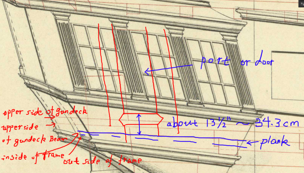
Maybe garyshipwright is referring to this? I found a draught of 3rd rate 64gun. The minimum measurement of this height is about 13 1/2", which is almost 34.3cm. It really needs a step or ladder to ensure safety. It's a tricky problem,there seems to be no model or book ever mentioned here with steps or ladders...
I will refer to Franklin's model to simplify this part - the so-called 'gray-zone'.

HJX
Hi HJX Thank you sir.I do believe that between what you have shown along with what Druxey said makes a whole lot of sense with the steep angle of the bottom stool. With the false floor shown in your drawing the steep angle had no affect on a person climbing down and falling forward. Gary
-
10 hours ago, allanyed said:
Druxey,
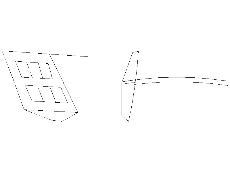
I understand the comment of the stools but not sure about the quarter gallery. Is the attached simplified and exaggerated sketch what you are referencing?
Thanks
Allan
Hi Allan. I believe what Druxey is saying is that there is a floor in the lower gallery above the stool which would have been at the sheer of the deck line and had the round up of the deck beams. Most of the time we think that like the upper stool which was not only the deck of the upper gallery but also the roof of the lower gallery. This also would keep the floor from having such a steep sheer to it like the stool. Make sense to me. Wish I had thought about the floor. Gary
-
On 6/7/2019 at 1:49 PM, druxey said:
Gary: The stool sits at the angle of the sheer. The floor of the quarter gallery is at the same angle and height as the sheer and round up of the deck inboard. Bend your mind around that! Fitting the floor to the inside of the gallery at the correct angles will amuse you for some time....
Thanks David.
-
Hi Mark and thank you very much. Yes sir there are a lot of pieces that seems to be floating. The form and how accurate the gallerys look, are based on the lower stools and how accurate they are placed, which is depended on the rails of the counter along with the sheer of of her which is based on the curve or sheer of the wale and the planking . Once you get all that right, and all the angles, in that order starting with the wale then every thing else seems to fall in place at least for the moment. O boy is this a mouth full. I do believe that I finally some thing right but looks good to the eye. I got a couple more pieces to place then I post up a couple of photos of the lower stools and its parts and pieces. Gary
-
Thanks druxey. Seems good sir, that getting the geometry right and looking good is the most time consuming and seems one moves at a snail pace when building this part. Of course you already know this. ;o) I thought building the head and its rails was a little on the hard side but working on Montagu stern has changed that. One has to have answer's to 50 question before shaping and cutting one piece of wood. Oops 30 pieces. On a question on the bottom lower stool that you and other good folks may be able to answer. The lower stool seems to set about 2 feet or so, have not measured it from the door but one would have to climb down in order to step on the stool. Is there a possibilty that a step was added? I looked in Boudriot 74 gun ship and its lower stool was just as low but didn't show a step for . Thank you
-
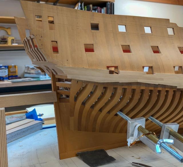
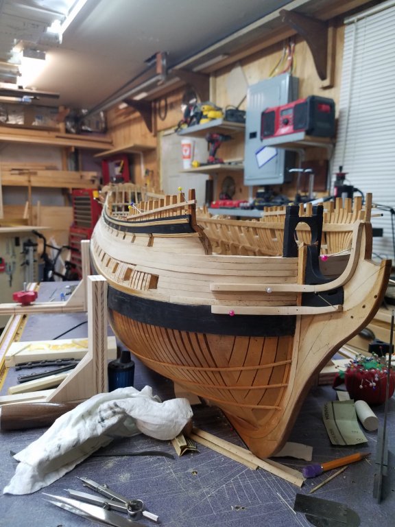
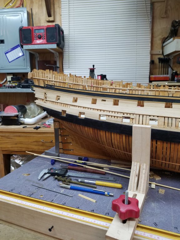
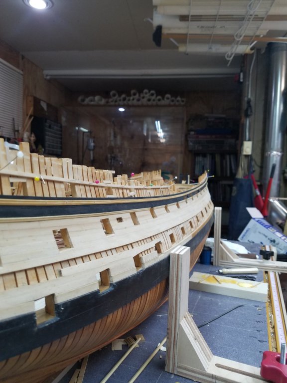
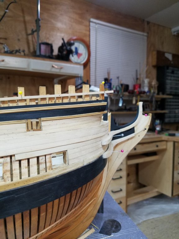
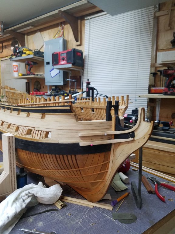
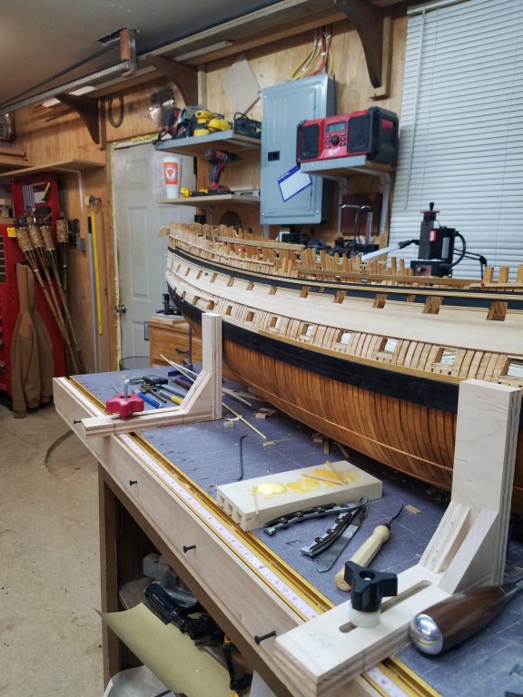
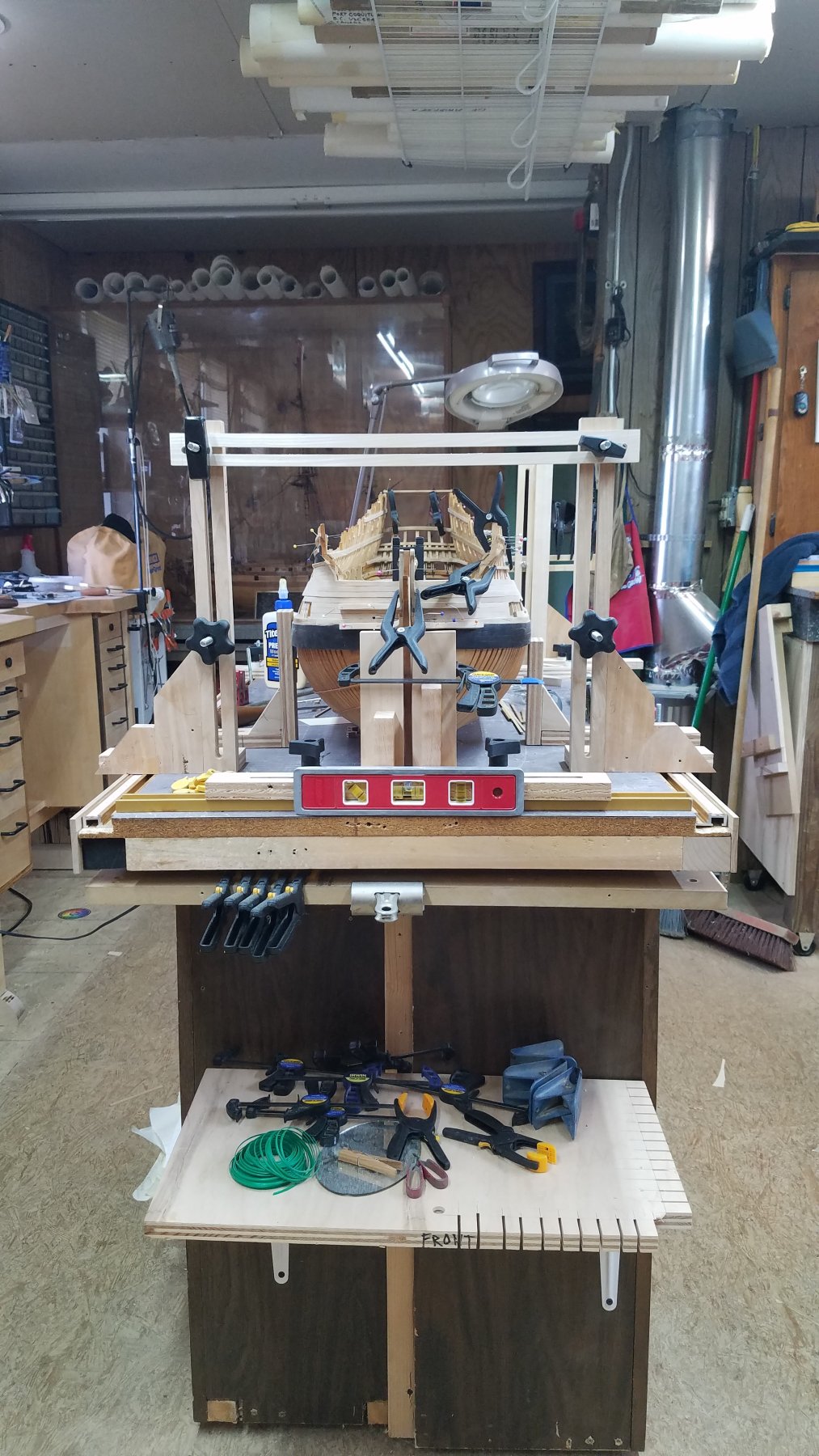
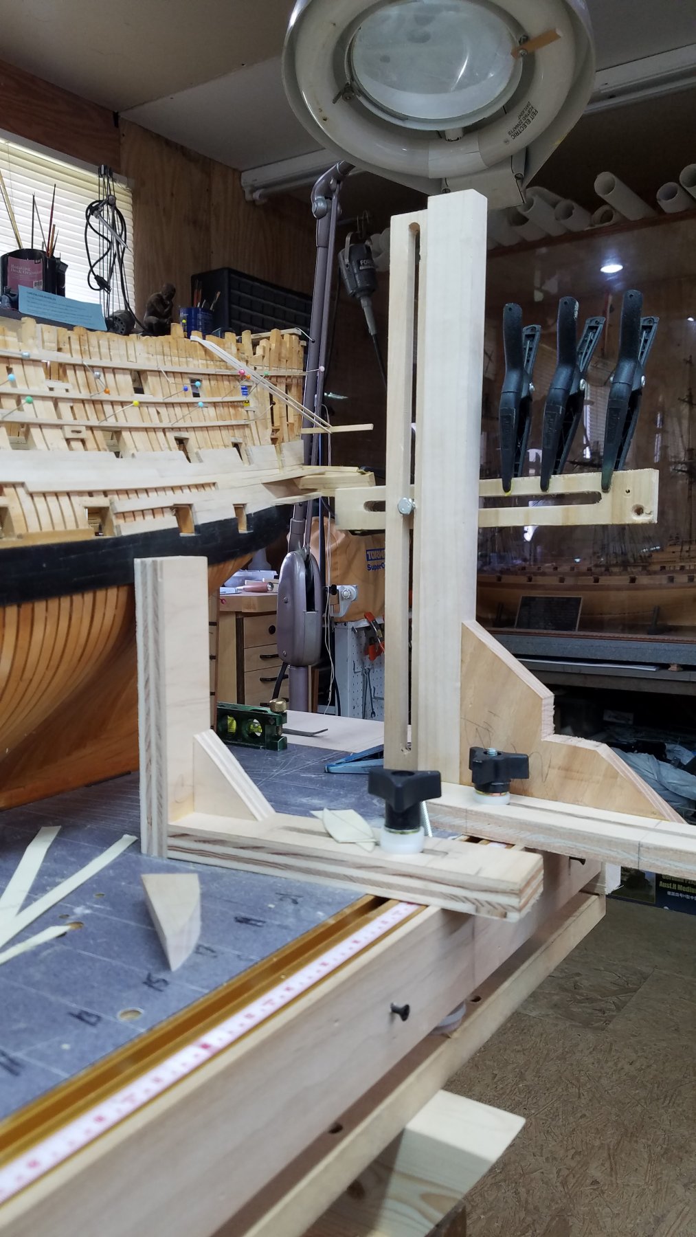
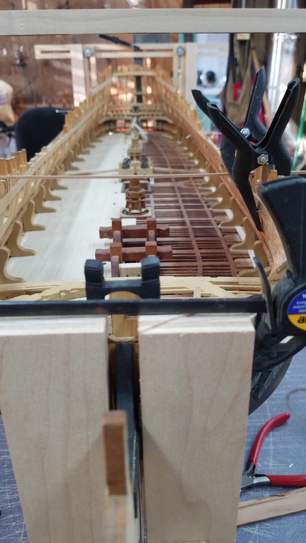
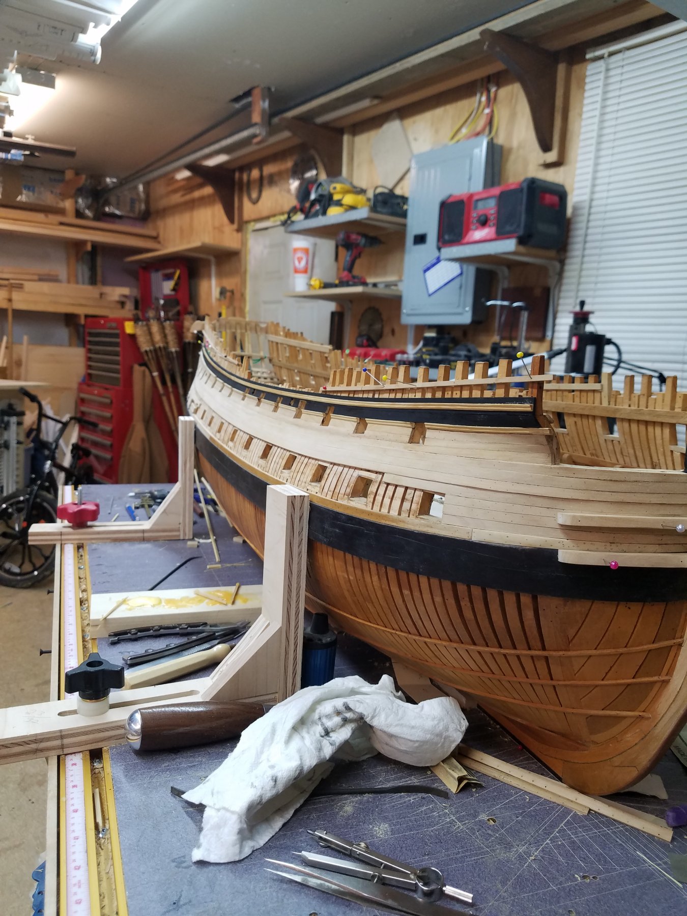
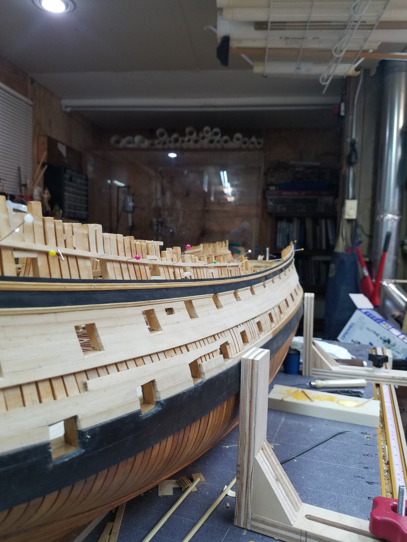
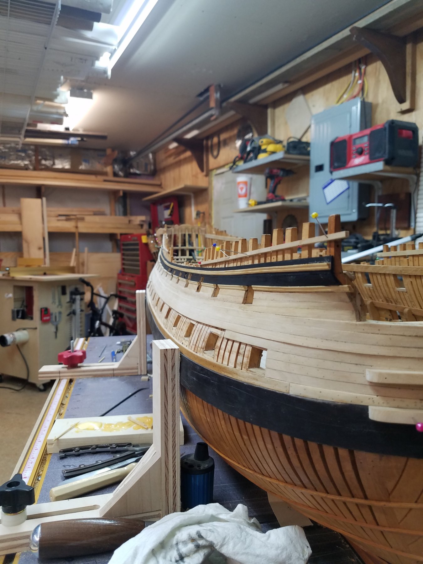
Well good folks I have been working on Montagu stern, probably on and off for the last couple of weeks and looking back seems that from the photo's it doesn't look like much as been made, that is untill you look at the parts and pieces that have been discarded. Sorry but I didn't take any photo's of them but did want to make sure that I recorded this for others who might undertake the Stern of their own 74 with a balcony trying to figure out they parts that made up the stern. It does at time's seem like a total up hill battle and lots of research on what is what on the stern which I am still trying to figure it all out but have some good builders that with out them my understanding would be a lot slower. Hope you enjoy the photos, just remember it a work in progress. Gary

-
-
-
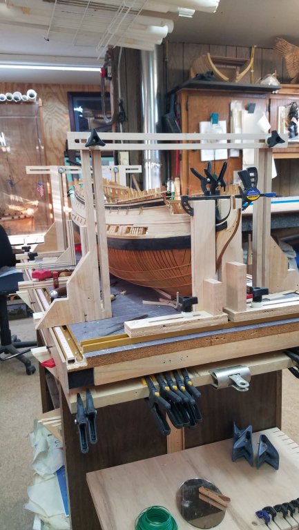
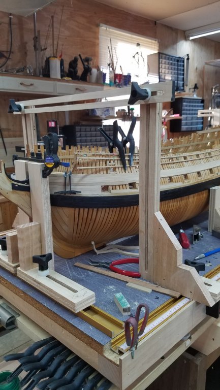
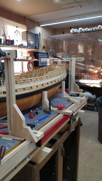
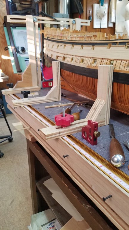
Hi Guys. Here is some photo's of Montagu at the moment with new items to help me get things square on her and to help with her stern and quarter gallery. Gary

- yvesvidal, marktiedens, druxey and 10 others
-
 13
13
-
Hi Bob. The protractor sounded like a good ideal so I order on and should be here early next week. Should really make the chop saw a whole lot more accurate. Thank you. Gary
- mtaylor, thibaultron and Canute
-
3
-
I just picked up one at Harbor freight yesterday and been playing around with it. It seems to be a good one, but time will tell. I have a 12 inch chop saw which I use as much as my table saw so figure that this little chop saw should fit in really nice. Now all I have to do is figure out how to make it a little higher so I can see what am cutting. Maybe a table on top of the table. . Gary
- mtaylor and thibaultron
-
2
-
Hi Druxey and Mark. You may be right druxey. Does seem that Montagu dimensions are different which keeps one on one's toes. Mark you are probably right sir. When you look at it, the cove doesn't seem to exist, the part that's right above the upper window's, which looks like curtains that go all the way across and unlike others such as her sister's which had good looking stern's. Her's looks a little on the flat side. ;o} O well, at the moment am having a blast and its nice to hear from you guys. Thanks for your respone. Gary
-
Hi Mark. Thank you sir for responding and does give one something to think about. Doing my research on the stern I found that model's of the Warrior and the Canada both 74's, have a taffrail fiferail. If you look at the plan its not there which doesn't mean much, that is untill you see the model which does show one. you will see that it has the fiferail but seems on the plan of Alfred her self doesn't show one. I do believe these plans are as build but not sure why the Warrior has one. Hahn didn't add one because it doesn't show up on her plan. Went through the plans and seems that there was more ships that had one then there was that didn'tll seems like there is a reason and hope to find out. . Gary
-
Hi every one. Just a quick question. It has to do with the taffrail and its height from the top of the keel. Steel gives the height of the taffrail at the middle, of 50 feet 6 inches from the top of the keel, are they talking about the trim also that goes around the top of the taffrail ? The reason I ask is in Steel plate he shows the taffrail fiferail which is setting, guess wise 6 inches higher, is this included in that height. Where does the taffrail starts and where does it stop? Thank you. In the mean time I check a few more things to see what I come up with. Gary
-
Hi Mike and Oskar24. Mike will do on the photo's sir. Oskar If I understand right Alfred and a few others are building Plank on frame like the real ships back then and the other method I believe is plank on bulkhead, which a lot of people builded. I believe that plank on frame is harder due to building up frames and other internal parts of the ship and plank on bulkhead is that the frames are plywood bulkhead installed on a keel and then planked on the outside once the bulkheads are sanded to accept the planks. There is a lot more to both types of building depending on were your interest ln the two. I have seen some really good Plank on bulkhead, but my interest is trying to build them like they was. Hope this helps. Gary
-
Hi Mike. Thank you and will do the same. How is your Agamemnon coming? If there is any thing I can do let me know sir. Seems like its been a long time. Gary
-
Thank you good sir. Gary
- Kusawa2000 and mtaylor
-
2
-
-
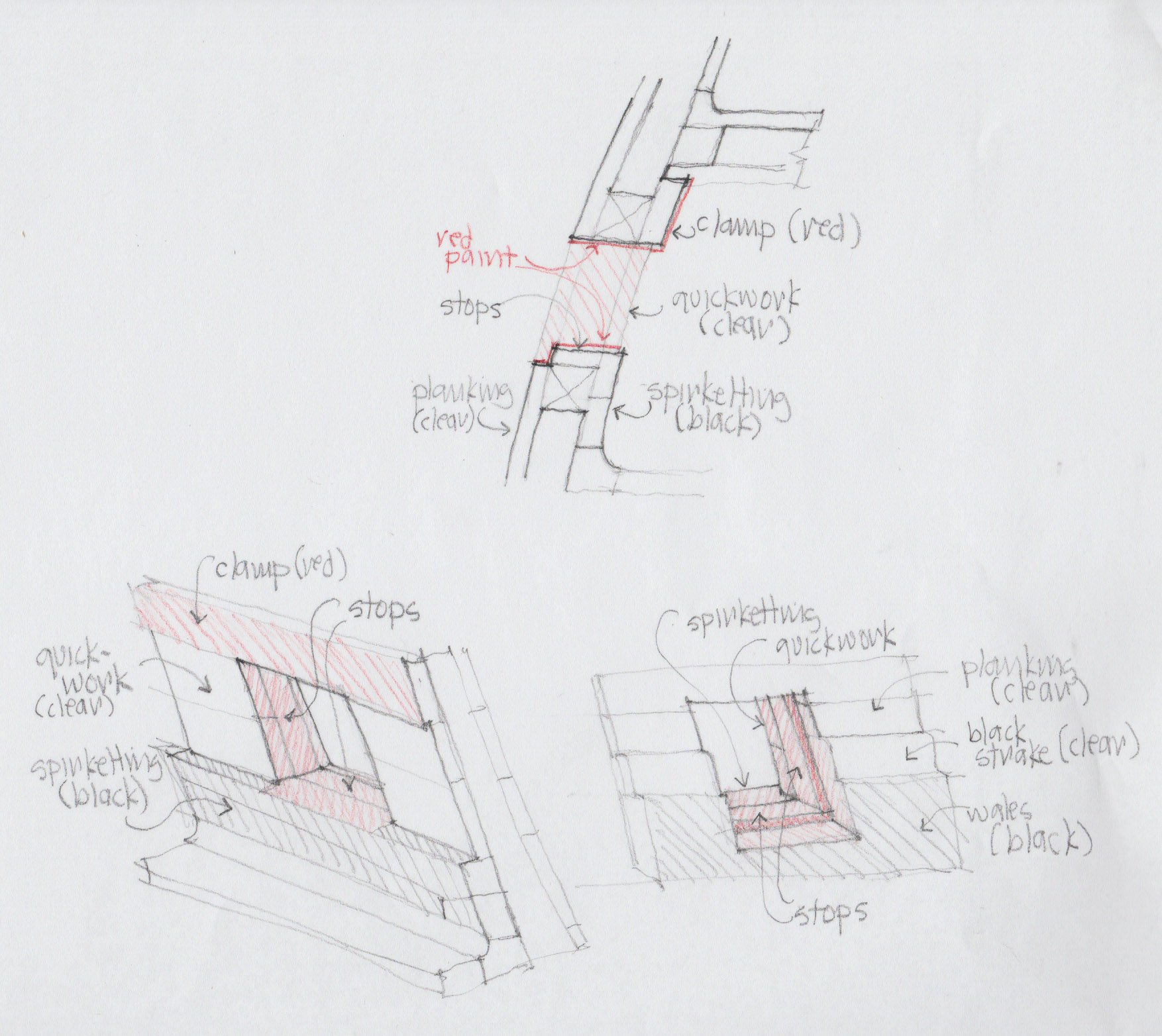
2 hours ago, SJSoane said:
Thank you, Amalio, for your kind thoughts. I have mostly learned from books and especially from the great modellers on this site. And a lot of mistakes!
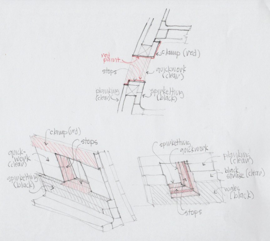
I am having to carve/shape the last two planks, and while taking a break from this, I looked more carefully at where paint/stain will meet edges and surfaces around the gunports. I have drawn a little sketch to think this through. I was surprised to see that the red paint comes over the top of the spirketting, meeting the black of the spirketting on a scribed line; and where the wales cross the last two gunports, I will have the black of the wales meeting the red of the gunport on the edge between the two, on the same piece of wood. And, the edges of the clear outboard planking will meet red paint on their outside corners at the edge of the port. These are the real test points of whether stain will work, or whether I need to edge these points with paint matched to the red stain elsewhere. Now I know what my test pieces need to look like.
Mark
Hi Mark. Nice job sir and I must say your drawing our outstanding. Mine comes out looking like a first grader in art class. Keep up the good work sir. Gary
- mtaylor, aviaamator, minimini and 2 others
-
5
-
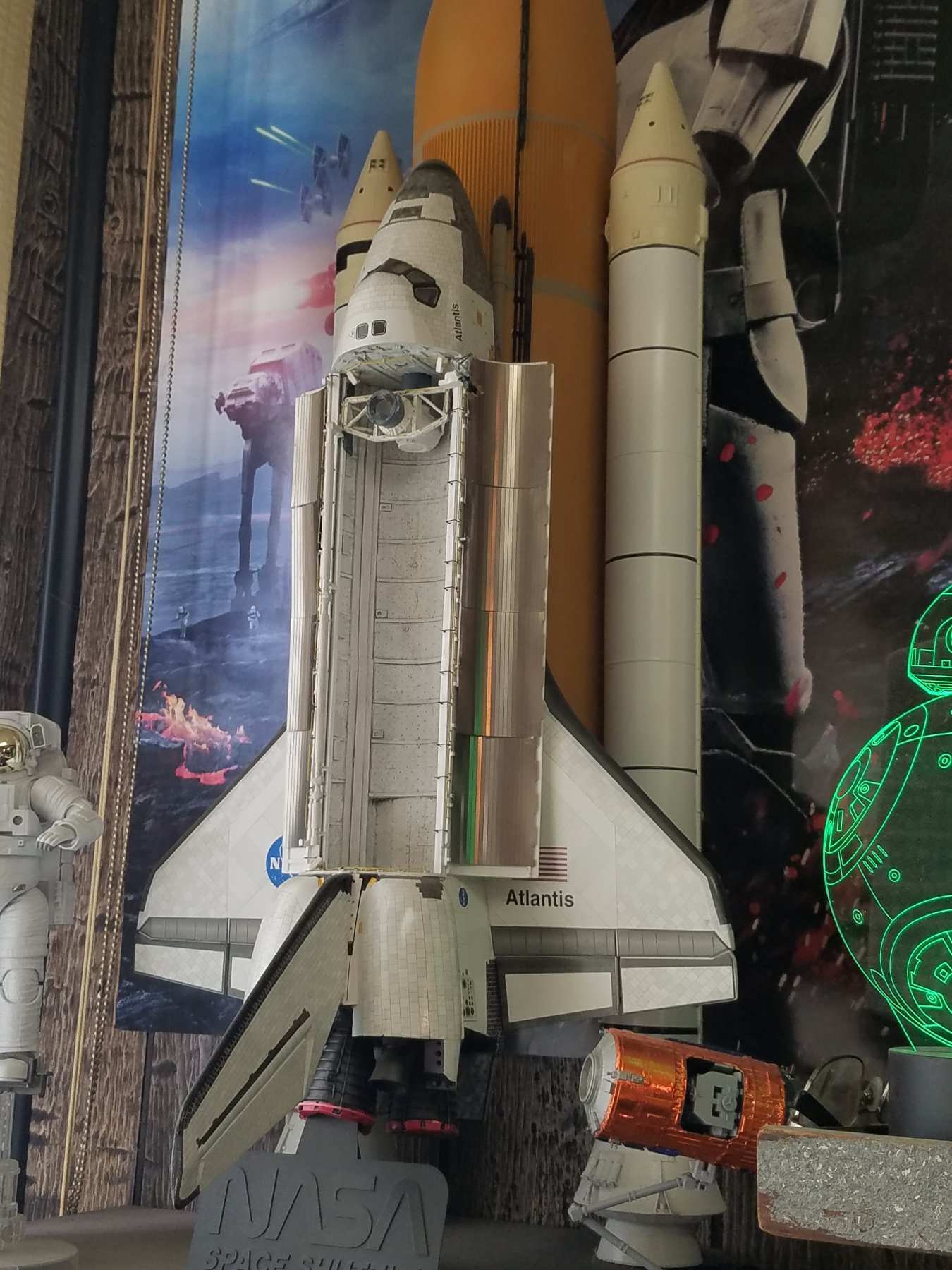
Hi Mark. how about air brushing the paint on. Tape up what you don't want paint on and spray on the paint. You can also cut in above the tape edge and it will stop the spray paint from seeping below the tape. Works good for me. You can even paint dye this way. Practice on scrap till you get it they way you want it. As they say practice makes perfect.Here is a space shuttle I painted and built from a kit. I think it came out not to bad. Gary

- aviaamator, Archi, dvm27 and 4 others
-
7
-
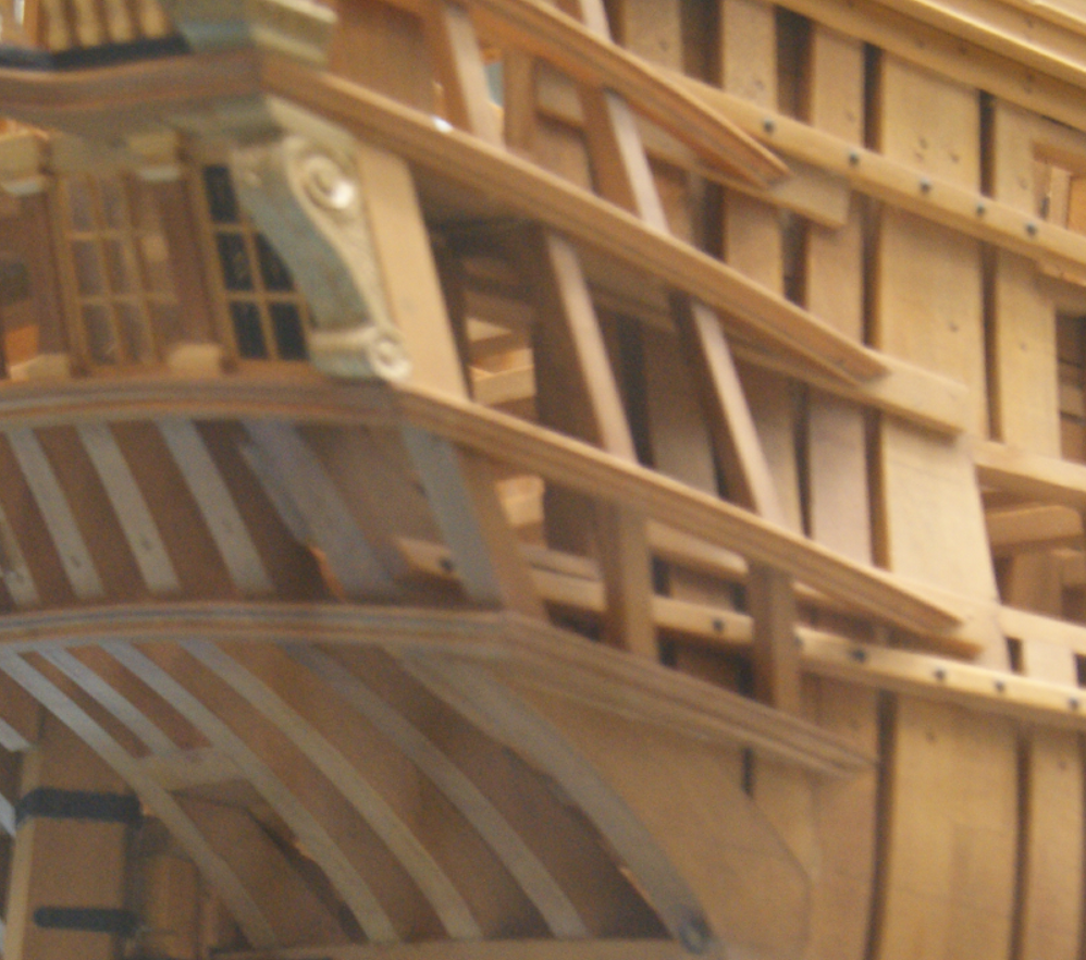
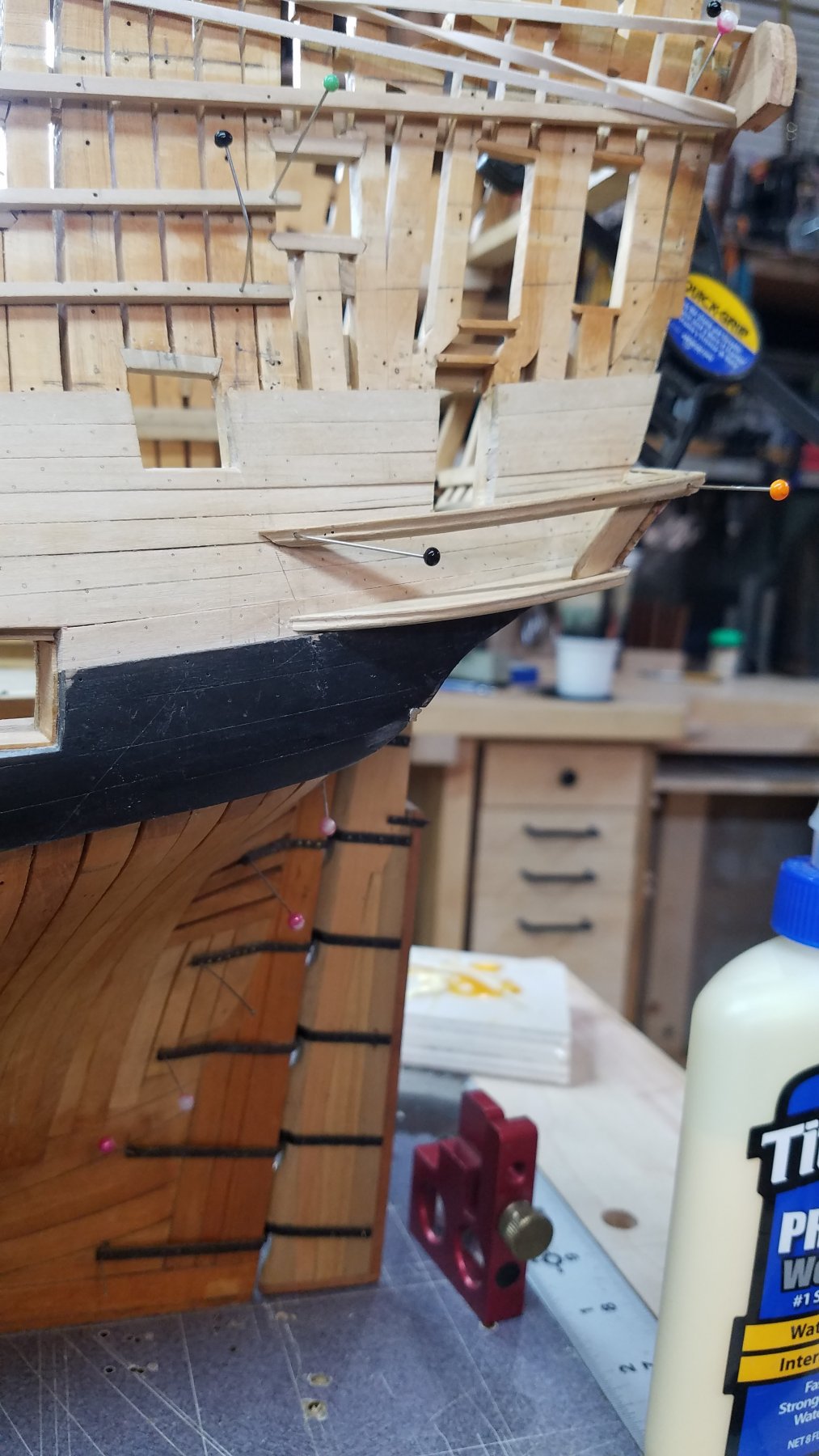
Hello Everyone. Seems its been awhile but some times life hits you between the eyes but I did get a little bit down on Montagu. Hope you enjoy the photo's. Gary


- Wintergreen, dvm27, JOUFF and 26 others
-
29
-
-
Hay Mark. Your doing good sir and druxy I do believe that model ship builders are some of the most humble, just look at their scrap box. Gary
- paulsutcliffe, druxey, mtaylor and 1 other
-
4
-
Hi Siggi. Went looking in the library and only came across two, one that shows the joint and one that talks about the hook and butt joints. The book 18th Century Shipbuilding, remarks on the Navies of the English and the Dutch, by Blaise Ollivier,1737 done by David H. Roberts and published and distributed by Boudriot. The other is The Anatomy of the ship The Bomb Vessel Granado1742 by Peter Goodwin. On page 52 he shows in figure 6/3 through6/6 the make up of Granado wale made up of 3strakes showing the upper and lower put together like your bottom drawing. Some would say the Anatomy of the Ship is full of mistakes, which I have found some but doesn't stop me from using what I think is right as long as you can back up what your using.I look and see if I can come up with some more for you. It also shows that the middle one as just having a butt joint. Gary


HMS Montague 1779 bygaryshipwright - 74-gun Alfred-class
in - Build logs for subjects built 1751 - 1800
Posted
Hi Siggi. Thank you sir. Your infor makes a lot of sense and if you was to measure up in your one photo from where the stool line is to the bottom of the door it probably would come out to be about two feet. That is a big drop down only to have to climb out of the quarter gallery. To me it makes sense that they added a floor which would of be laid at the same height as the deck it self. This way all one would have to do is step over the sill on to the floor and use the bathroom. Being they were the higher ups the higher ups would do their best to make them fill comfortable and jumping down would have been a pain in the butt. Gary