Hubac's Historian
-
Posts
3,304 -
Joined
-
Last visited
Content Type
Profiles
Forums
Gallery
Events
Everything posted by Hubac's Historian
-
 This is yet another marvelous creation in my “favorites” folder. I’m glad to see work resume!
 -
Will you cut away the lower hull for your waterline display, Europapete? If so, I will advise you to assemble the hull, whole at first, and then attach sturdy bracing beneath the lower deck, before cutting. I learned the hard way that cutting before assembly makes it very difficult to fair to a true waterline, for one, and it also introduces distortions to the upper hull that do not become apparent until much later in the process. It was nonetheless necessary for what I was doing, but for the Victory these problems can be avoided.
-
Thank you Kevin - I appreciate the kind words, and I can assure you that with sheet plastic, anyway, this kind of scratch-work really is not that difficult. The main thing is staying in scale. This is the first model I have made where I have attempted any of this sort of modification. Mostly, I’ve spent a lot of time thinking about how I want to go about it, and often enough - it works out. Sometimes I have to throw away and take a different approach. I had some prior experience with the Modelmaster acrylics when I did my first SR, so many years ago. I liked them so much, and knew I could achieve reliable results with them. The rest has been a process of trial and error. I did a number of sample mock-ups with the un-used portions of my vulture-carcass hull (that I extracted extension pieces from). Part of the reason this has all gone on for so long is that I am very deliberative and methodical. I don’t really care too much how long it takes.
- 2,699 replies
-
- 7
-

-
- heller
- soleil royal
- (and 9 more)
-
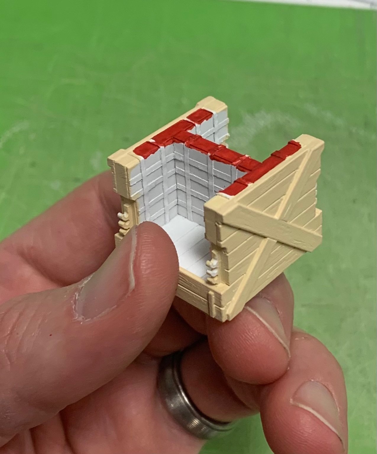
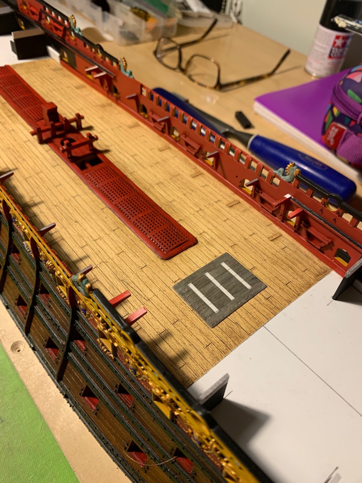
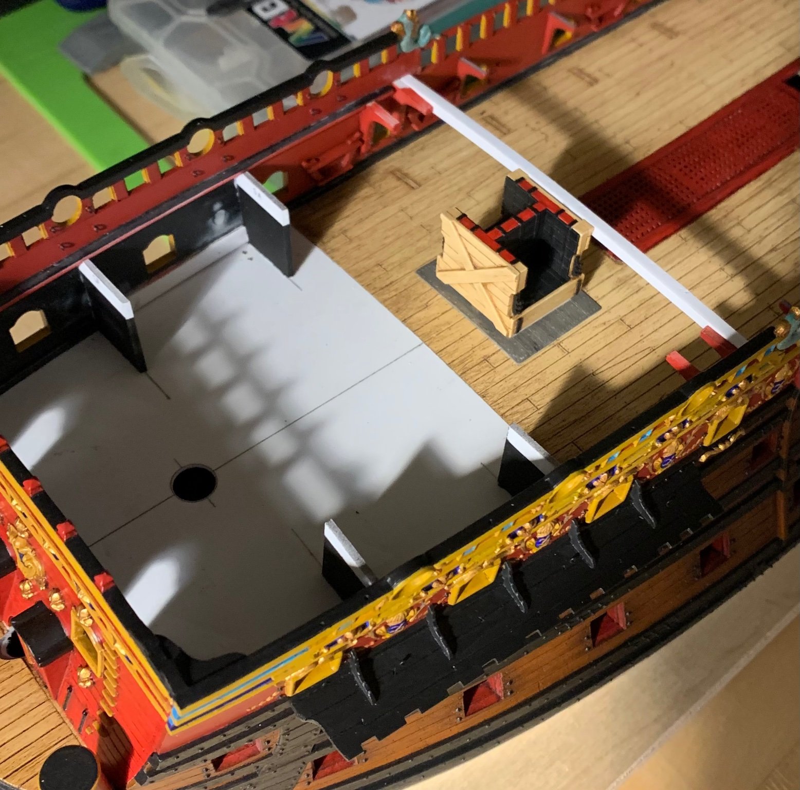
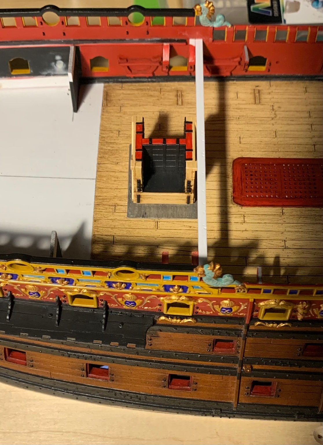
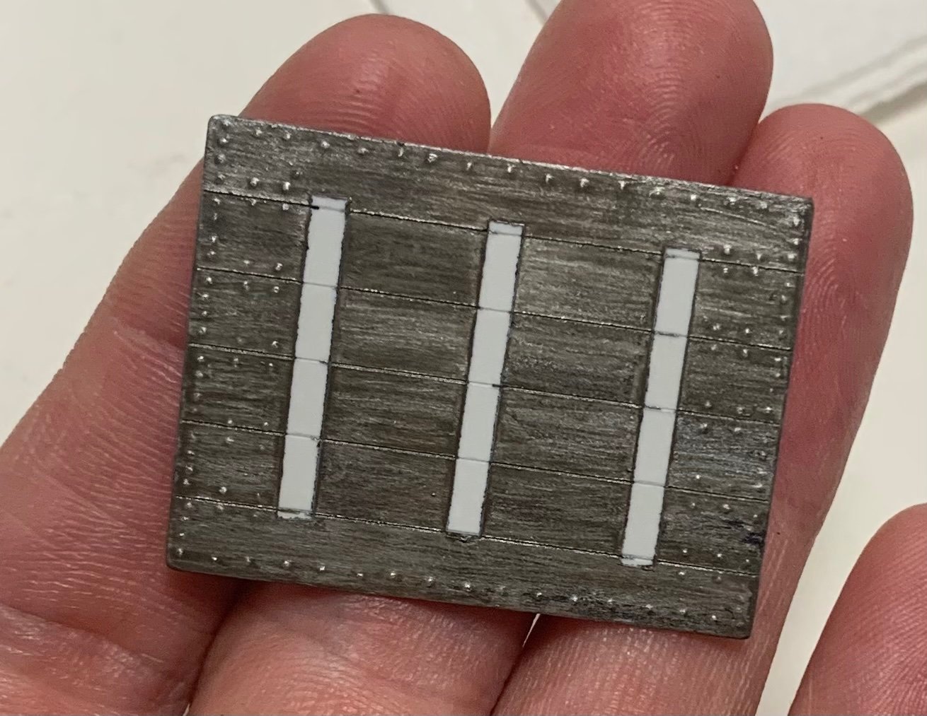
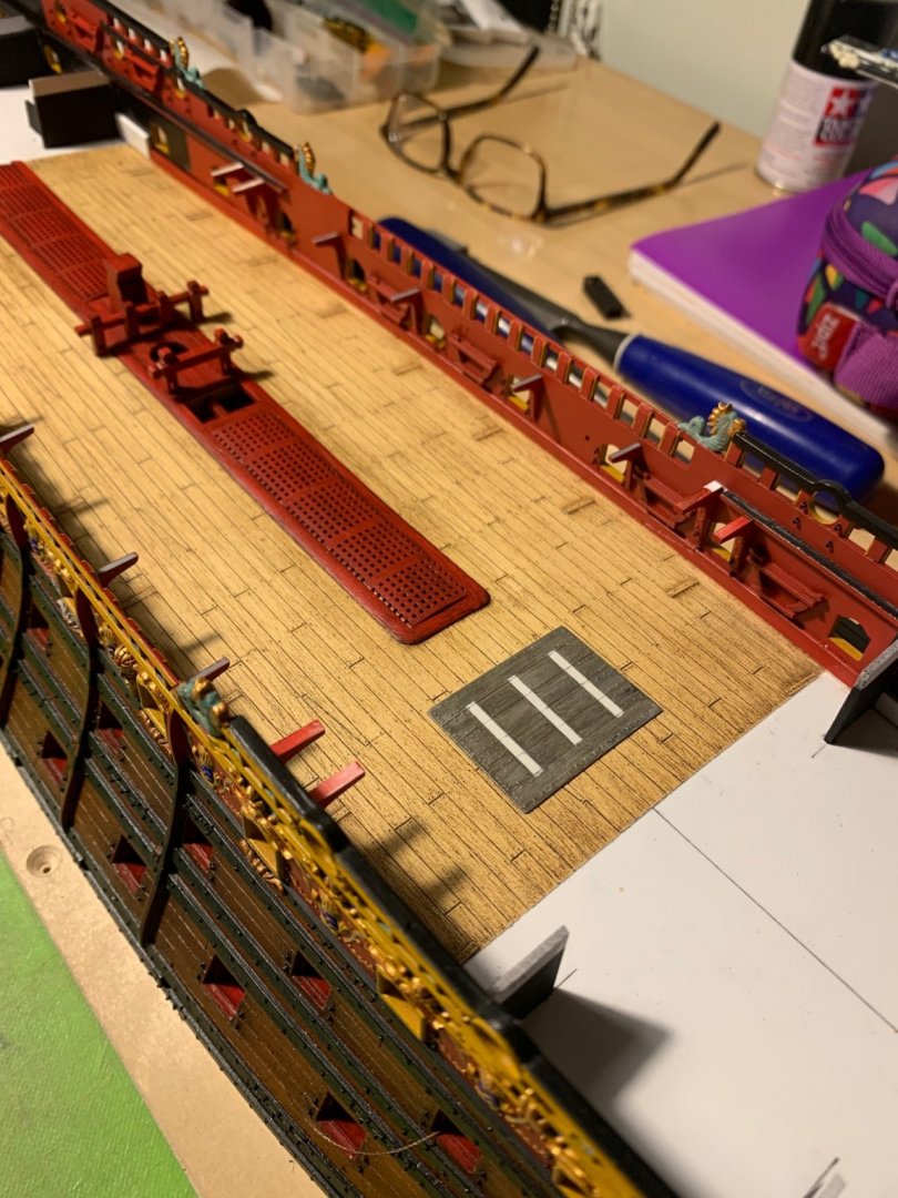
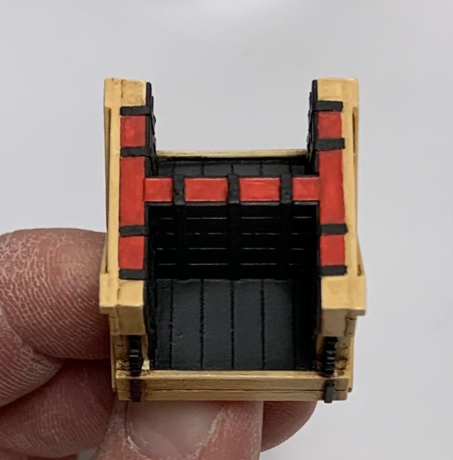
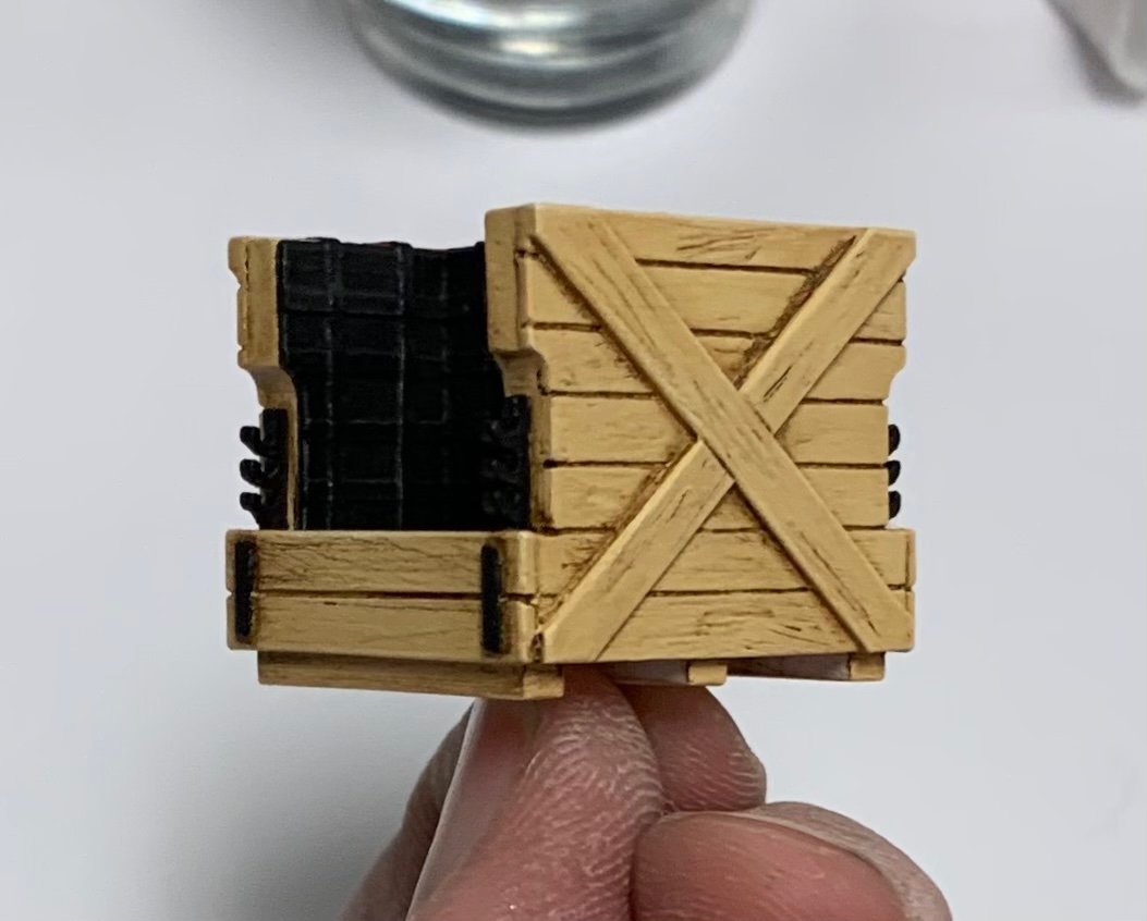
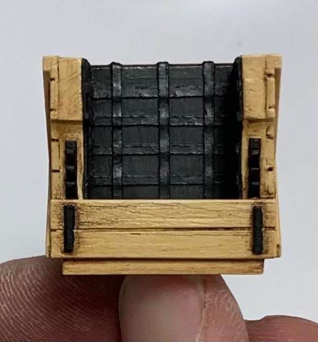
We’re literally coming down the home-stretch with Dad. We moved his furniture and belongings, this past weekend, and we will move him this coming weekend - HUZZAH! Naturally, work on the ship is fairly meager, but I did get the deck sheathing and stove painted, and I did manage to make-up and fit the forecastle beam that will be visible at the break of the forecastle deck. A montage that shows my paint processes, particularly for my natural “oak” finish: For some reason, I can’t load the other two pics of the sheathing because of an “unknown server error”. Anyway, the process is pretty straightforward; flat black spray primer, followed by Citadel silver (allowing some black to peak through), finished with grey enamel wash. The enamel wash picks up all the nail heads and sheet seams nicely, while giving an oxidized metal finish. The white stripes are masks for where the stove glues down. The stove begins with Modelmaster Random Tan as my base coat over white enamel primer: Although it will never be seen, I chose to represent the brick work that is sandwiched between iron and wood. Next, I slather the whole thing in Windsor and Newton medium grey oil, and allow it to sit for five minutes, or so, before wiping most of it away. This paint gives the wood a pleasing silver-ish cast, like newly oxidizing oak, and it gets into all the plank seams and grain structure: Next, after allowing it to cure for a few days, I do the same thing again with W&N Van Dyke Brown. This is what restores a sense of woody warmth to the surface, while enhancing texture and depth: The plate mounted to the deck: The iron blacked-in: I decided to rub some powdered graphite over the black, so that the lattice would pop a little. Again, this will never be seen, but I wanted to play around with powder effects. It is subtle, but effective: Lastly, the stove on-board: The stove gives me a central glue connection for that beam, which will lend some rigidity to the whole deck structure. In other news, I have 2 of 3, aft bulwark gussets fitted and installed. All the prep work on the last bulwark is done, so I will resume painting soon. I hope all are well, as the holiday approaches. Thank you all for stopping by. More to follow!


- 2,699 replies
-
- 19
-
-
- heller
- soleil royal
- (and 9 more)
-
The only issue I can anticipate with your proposal for mapping the quarter gallery join is that - at least as far as the Heller SR is concerned - the hull wall thickness does not seem very consistent from one side to the other, nor from one level to the next. The Vic, though, is all around a better kit and less plagued by fit issues. It’s been a while since I fiddled about with my un-built Vic, but I remember thinking that the hull pressings were somewhat thinner-walled and that the quality of the moulds was very high. i know you will figure if out.
-
That is an enviable shop set-up, Frank. Congrats on this transition in your life. As always, your work is impeccably clean and progressing nicely. Glad to see you back.
- 510 replies
-
- 3
-
-
- reale de france
- corel
- (and 1 more)
-
Great tip with the poly! My son is the skateboarder, and he likes to convey himself from one room of the apartment to the next on his skateboard. He stopped riding it outside because - I don’t know why, actually. The funny thing that dawns on me about the Heirloom Furniture Project, as we presently are consolidating our Dad’s house-load of large (but very nice) furniture, is that I wonder whether my daughter will have the space or interest in taking the bookcase into her home, after we are gone. I am only taking one small Hepplewhite table from my Dad, eventually. I guess I could hardly blame her if she sent it off to the auctioneers.
-
Very nice!
-
The Speedwell is an excellent subject, IMO, and a really good melding of draftsmanship and kit design. I wanted my first POF build to be of a smaller subject, and this really fits the bill. I am excited about this!
- 1,784 replies
-
- 1
-
-
- winchelsea
- Syren Ship Model Company
- (and 1 more)
-
This is just incomparably better and more crisp than the stock stern plate and quarters. Mega-impressive!!
-
Yes, John, it is often noted of Laurent Hubac that he was among the most intransigent of the First-Marine shipwrights. And while the review between SR and the Royal Charles seems to favor the RC, SR was regarded as a maneuverable ship under sail, and a stable gun platform. Despite the additional width - that the building councils were trying to move away from, in favor of length - Msr. Hubac must have known a thing or two about building warships. As it pertains to deck access to the poop and poop-royal decks, that is definitely a problem that neither Tanneron nor Heller addresses with SR. However, Tanneron does address it on Le Brillant, albeit in an un-satisfactory way: Here, the foot of the poop deck ladder falls directly in front of a gunport. My answer to this problem will be to extend a short gangway from the poop and poop-royal decks, so that I can drop a ladder (oriented East/West) between the guns. I will likey craft a vestigial, inboard rail for these short gangways, that is ornamentally consistent with whatever I make up for the deck railings at those levels. As for the waist gangways, you raise an interesting question that I don’t really know the answer to. On the one hand, there is the outboard timberhead railing that would have been about waist high, in reality. I don’t think it would necessarily be wrong to craft a light stanchion railing, on the inboard side. I can’t say for sure, though, but I will look through my image files. What is lovely to look at is Marsalv’s amazing build of Le Gros Ventre. I am particularly intriqued by his treatment of the waist gangway. Just scroll to the more recent posts: What does seem sensible to add, for sure, are support stanchions, between the guns. I also like his lightly ornamental stool steps to the f’ocsle and quarter decks. By the way, you might recognize the stove, here. Although it is from a later time period, I chose Marsalv’s stove as the model for my own, as it was not wildly divergent from what is suggested in the SP monograph, and it seemed simple enough in its construction to be plausible for this earlier time. Regarding the discussion of exotic mouth meats, I suppose I’d be game. It isn’t as though the animals have a mean tobacco habit, or any other nasty things happening in their mouths. I’ve not yet tried it, though.
- 2,699 replies
-
- 7
-
-
- heller
- soleil royal
- (and 9 more)
-
Wow - those are some sweet rides that you’ve brought back to life! Cars are a dream of mine, as I’ve never owned one I could be proud of. Cocktail brunch - you are welcome any time!
-
What eras of cars interest you, Keith?
-
UhOh! Are you inviting me to take you on a tour of Marc’s museum of wooden objects? AKA, the “Heirloom Furniture Project,” AKA things my children think of in terms of “all that careful surface prep, so please mind your skateboard in the house?” Those things that I’ve been diligently repairing and refreshing because they are my only true professional legacy? Back before my return to ship-modeling - when I was still making furniture - I kept a page on Fine Woodworking’s members’ gallery: https://www.finewoodworking.com/tag/marc-laguardia Interestingly, they appear to have taken down my Maloof rocking chair copy. The online edition of the magazine once used a picture of my rocker in a brief article exploring intellectual property theft. While the chair I made IS very faithful to the Maloof design, it was not made for sale; it was a gift. Further, I patterned the chair from Sam’s own video explaining how he goes about making them, and also with the help of a few coffee table books of his furniture. Anyway… THOSE WERE THE DAYS! Eric, I’ve always wanted a nice set of Stanley socket chisels, just to have them. I like that you finished your Dad’s project.
-
I think that the Captain’s supper was often a dish served cold, as galley cooking likely only happened when swells were manageable. That might be why Tourville was such a determined man - hell or high water, he wanted to run through the teeth of the enemy and get back to his warm hearth at home 🙃 C’est possible.
- 2,699 replies
-
- 4
-
-
- heller
- soleil royal
- (and 9 more)
-
Hi Keith, Your question is a good one, and I can only surmise that the fore and aft faces of the stoves are boarded-up to provide a buffer from the following wind. I wonder, also, whether the tall stern structure doesn’t provide some additional buffering effect for beneath the forecastle deck. The trouble, as far as I can see, with placing the stoves further aft is that there is less hull beneath the stoves to support their weight, and there is already a heavy super-structure above them. I am always happy if anyone can provide hard knowledge on this subject, as I am really just reasoning through it in my own mind.
- 2,699 replies
-
- 2
-

-
-
- heller
- soleil royal
- (and 9 more)
-
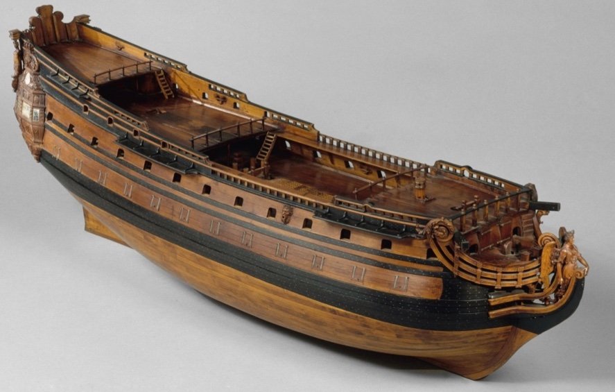
Hi John, On the SP, there is no forecastle deck to provide cover, so the stoves would need to be placed on the middle deck. For SR, it makes sense to place the stoves in the center of the main deck because there would be forecastle guns above where the vents need to be. Also, from a practical standpoint, this heavy counterweight is better managed - if it does need to be higher up on the main deck - along the ship’s centerline, as opposed to the ship sides, which are already balancing the weight of the guns. The other practical problem with placing the stoves between the guns is that it would make working the guns in that area that much more cramped and difficult. I’m really relying in the English dockyard models as evidentiary proof that the stoves on a French First-Rate, with a forecastle, should be placed centerline, beneath the forecastle deck.
- 2,699 replies
-
- 3
-
-
- heller
- soleil royal
- (and 9 more)
-
I am definitely interested in a POF model, but it isn’t something I would take on any time in the next five years, or so.
- 1,784 replies
-
- 2
-
-
- winchelsea
- Syren Ship Model Company
- (and 1 more)
-
Few people are, and at best - I’m making an educated guess, here.
- 2,699 replies
-
- 3
-
-
- heller
- soleil royal
- (and 9 more)
-
Very nicely done! I appreciate your fail-safe approach to glueing. I am similarly inclined.
-
Thank you, Mark. As best I understand the time, the stove would have had metal sheathing on the deck. The sleepers provide some extra separation from the stove box, and the box would be packed with sand, then a brick layer, and finally the bricks would be cloaked in these iron plates.
- 2,699 replies
-
- 4
-
-
- heller
- soleil royal
- (and 9 more)
-
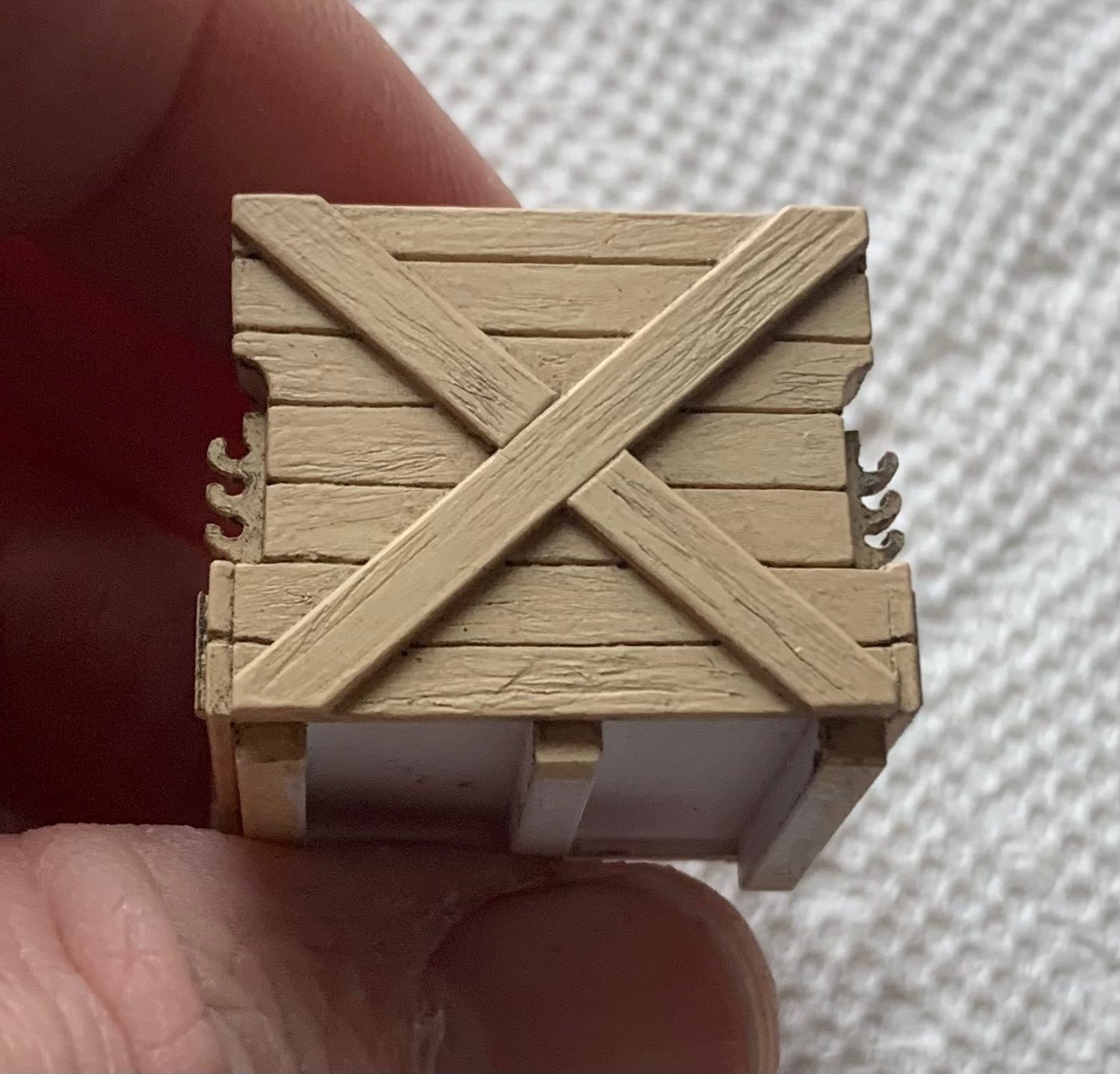
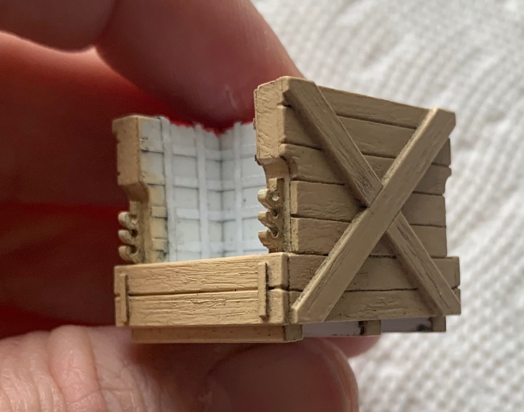
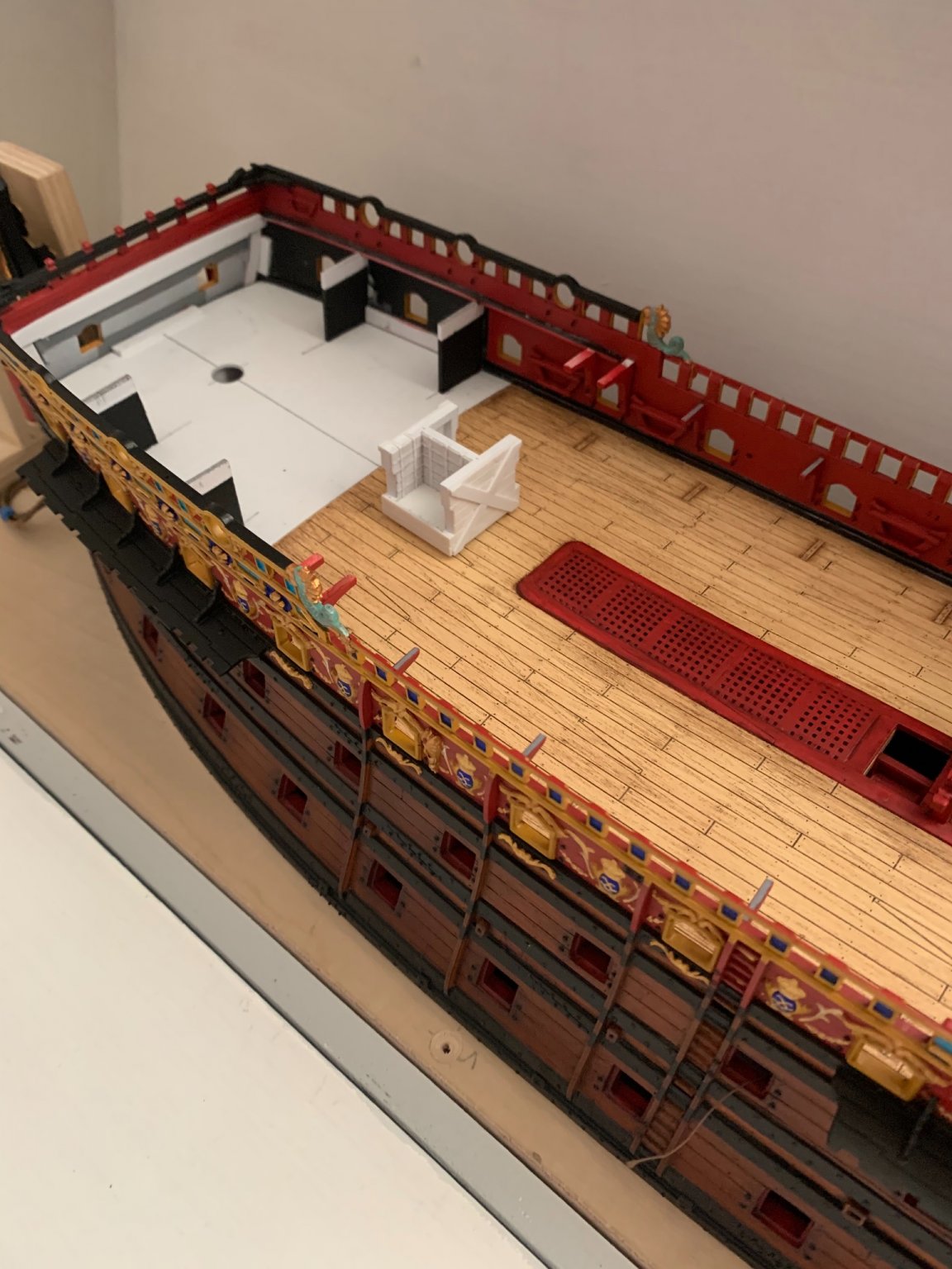
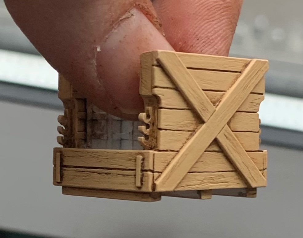
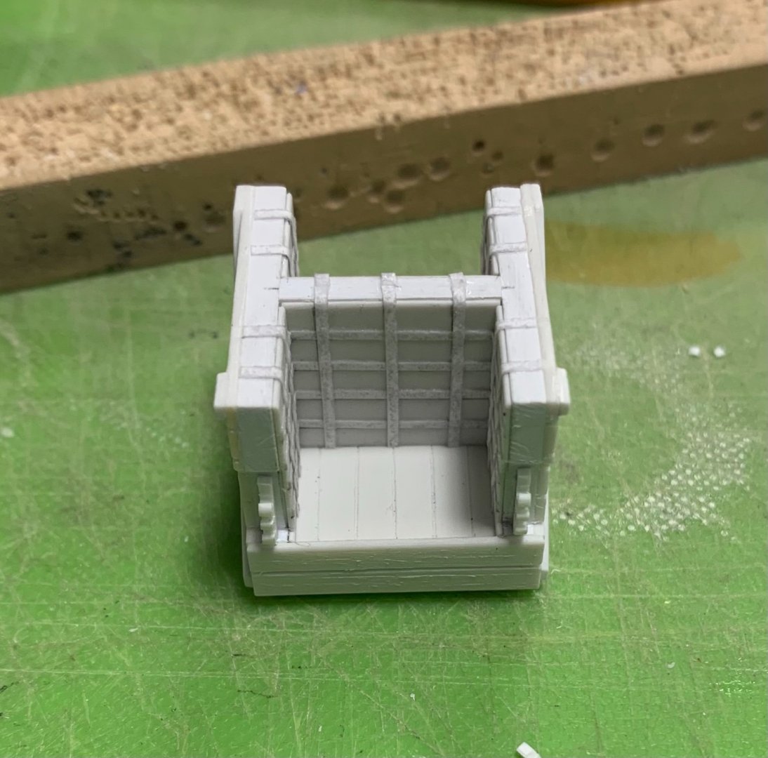
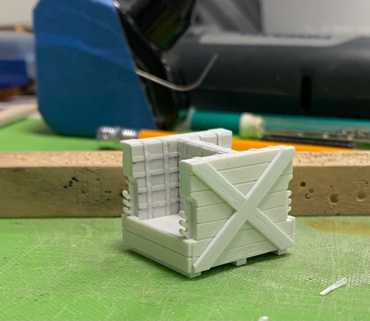
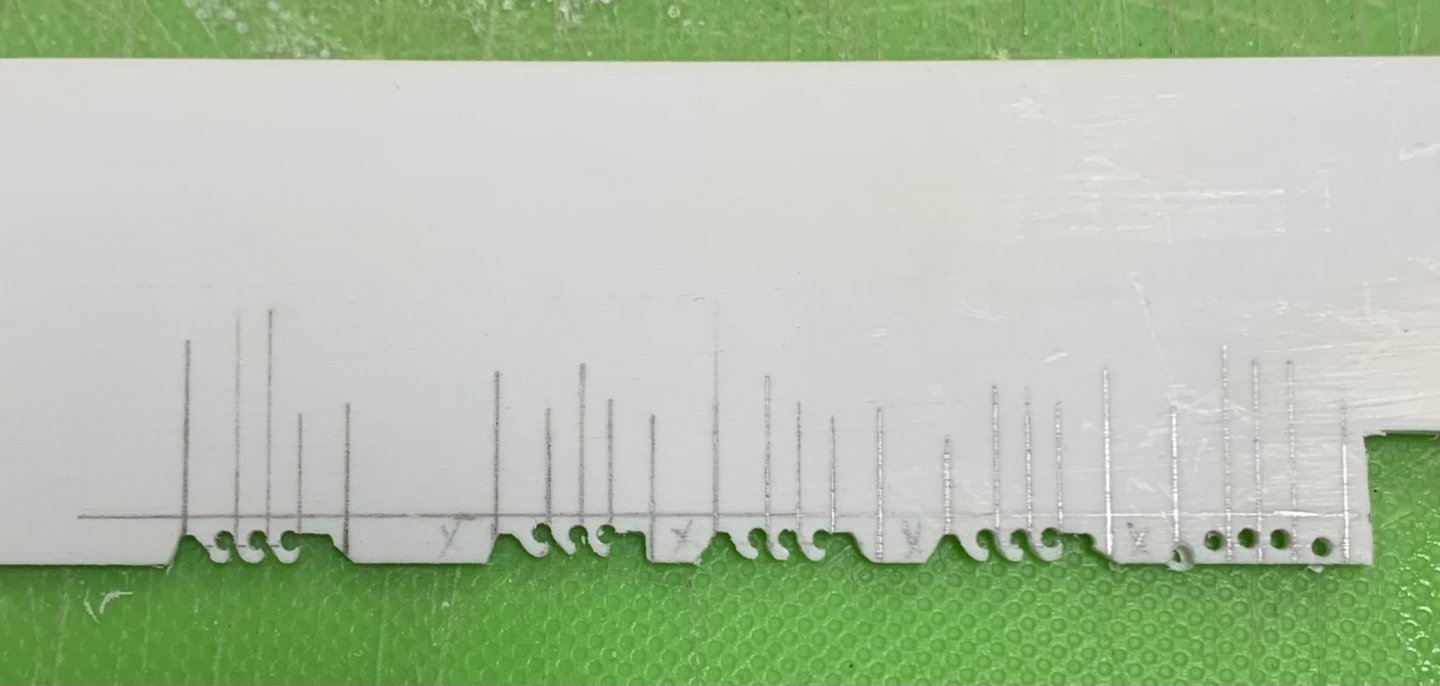
The stove is ready for paint: The best scale effect for the lining plate lattices was pedestrian typing paper cut into narrow strips and CA’d in-place. I sanded coarse scratches into the planking, so that the exterior will pick up the Van Dyke Brown distressing well. I still need to make the “metal” deck sheathing that goes beneath the stove sleepers, but that is a simple thing. I’m close to being ready for paint on the aft, starboard bulwark. I took even greater care in fitting this last piece because I did not want to deal with any putty at all, on the outside seam. Paint touch-up was a real pain for the three bulwarks prior. More to come! Thank you for your interest and for stopping by.

- 2,699 replies
-
- 15
-
-
- heller
- soleil royal
- (and 9 more)
-
Wow - what a collection!
-
You are, by far, your own worst critic. This all looks wonderfully crisp and clean. Forge ahead with confidence, Mark!