


gsdpic
-
Posts
523 -
Joined
-
Last visited
Content Type
Profiles
Forums
Gallery
Events
Posts posted by gsdpic
-
-
Thanks to all for the likes, comments, tips, etc.
I've taken a little break for a photography trip along the coast of Maine and Acadia National Park, but I am back now. And yes I stopped at Bluejacket to check out their finished America and all the other finished models in their store.
As for mine, I am working on shaping and cutting the deck beams. Once I get a little farther with that I will do another post with a picture or two. Not sure when though....I am sure I have fallen farther behind at work and I have a ton of pictures from my trip to post process yet.
- Nirvana and Duanelaker
-
 2
2
-
Thanks for the comments, replies, clarifications and likes...
Tim, I recall your build log is one of the ones here that I looked at when I first got this kit. I am sure that I'll be referencing it and the others more as I get into deck fittings and rigging and finishing. And thanks for the suggestions...I've heard a lot of good about the Syren products so that is a definite possibility. As for painting vs staining vs coppering....I don't have to decide until after I see what my planking looks like and how many mistakes I need to hide. Sails might be interesting, though that decision is even farther down the line.
-
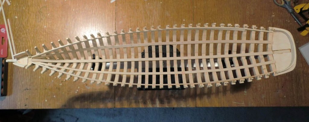
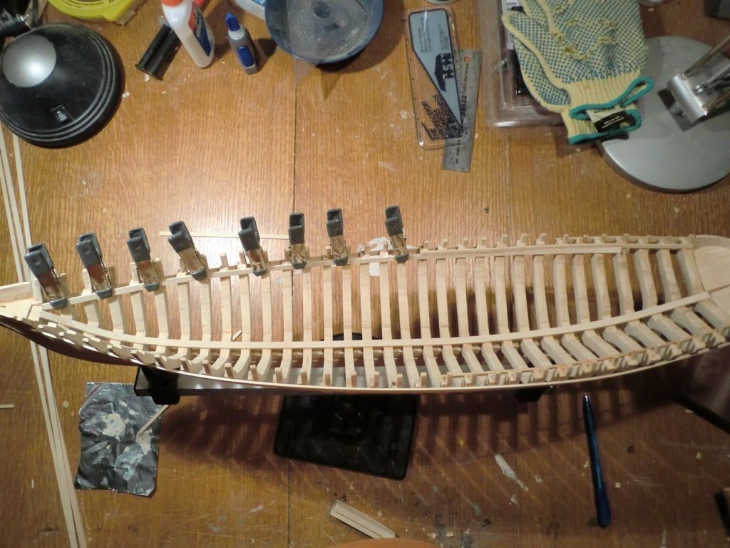
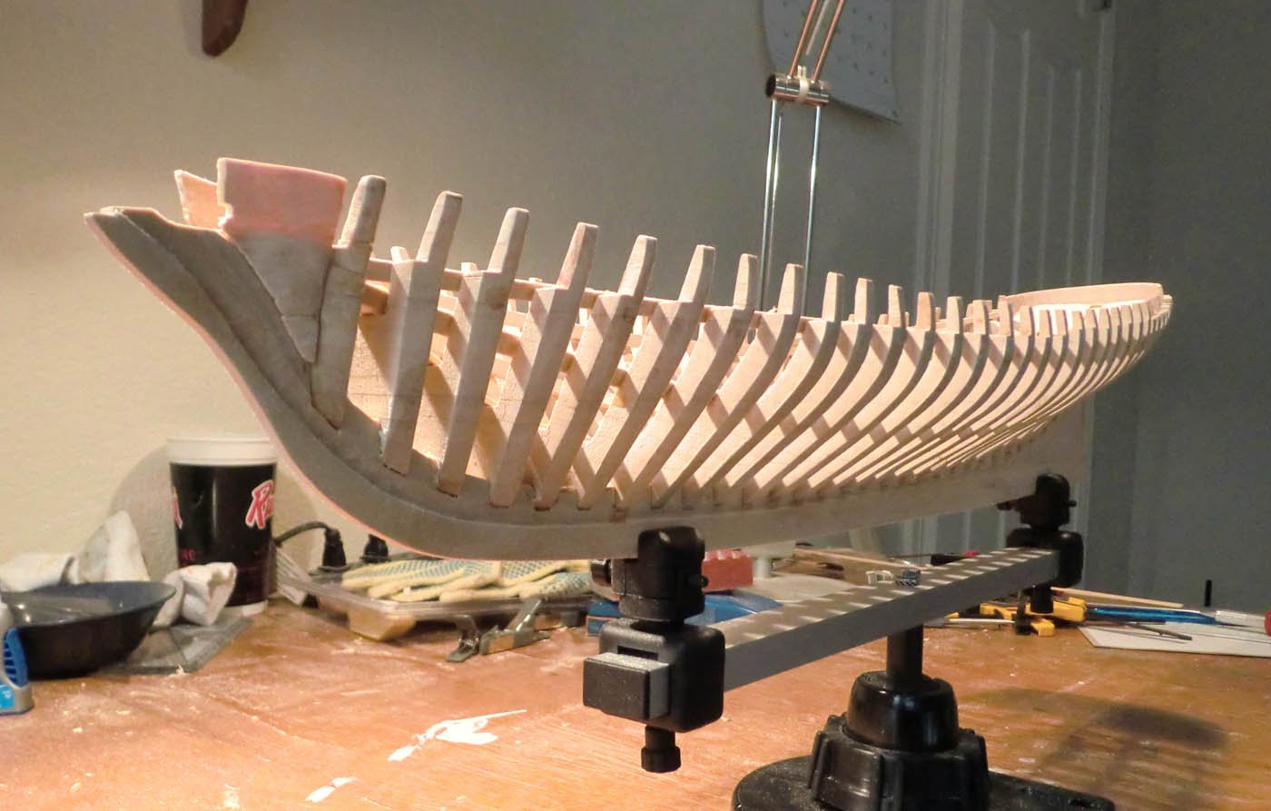
Another quick update....I finished putting in the sheer clamps and bilge clamps. I have done more fairing of the hull, especially the port side, but have a bit more to do. A couple of the frames have some low spots that I need to shim a bit (e.g. in the first photo, you can see that the second to last frame on the starboard side is not wide enough). I also have a bit more trimming and tweaking of some of the timber heads. And I am sure I have a bit more accidentally breaking off and gluing back on some of the timber heads as well. The carved bow piece is pretty rough....I'll have some repairing and filling to do there.
According to my log, I am up to about 63 hours of work on this project.

- Robin Lous, coxswain, Papa and 8 others
-
11
-
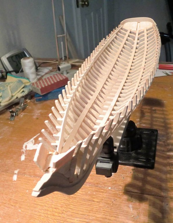
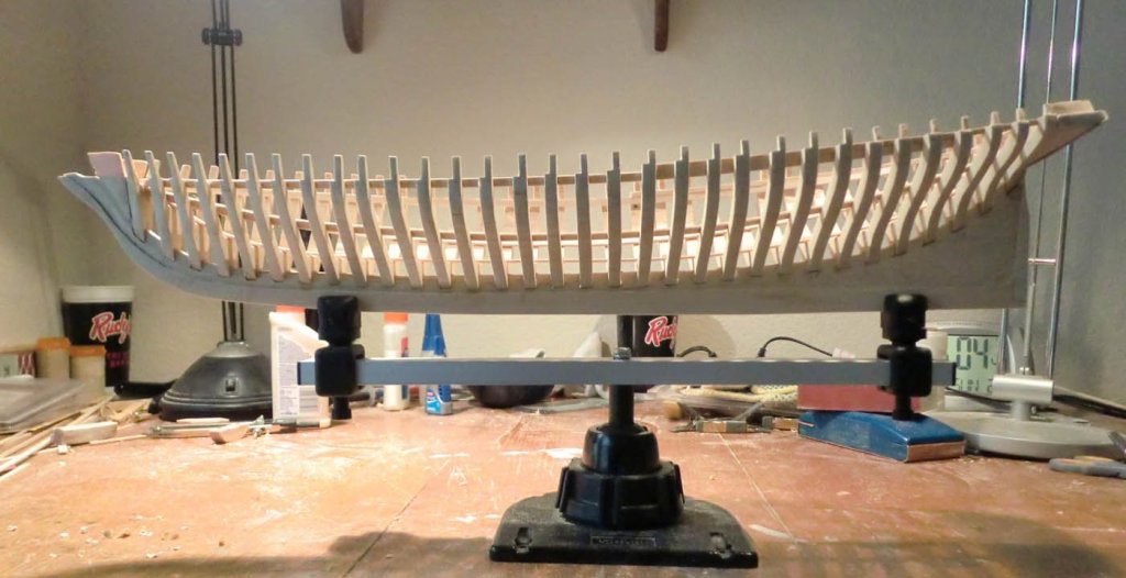
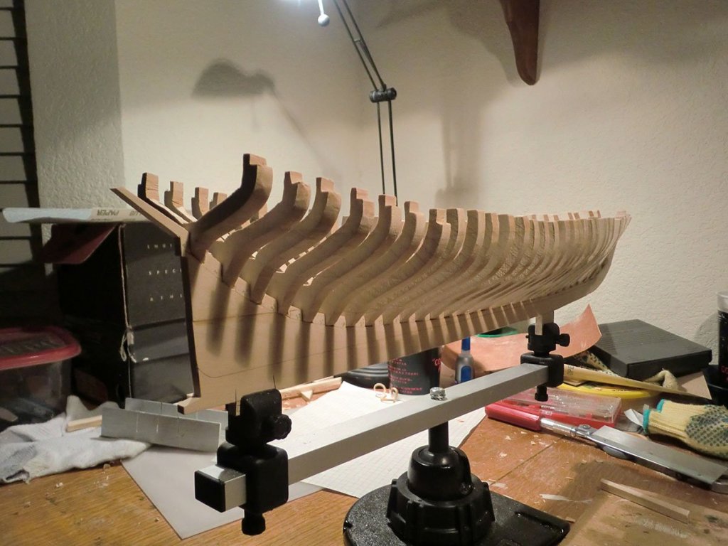
Been a while since I posted. Progress has been very slow, mostly due to not finding much time to spend on this kit. I have finished carving the bow and stern/transom pieces and affixed them to the model. I put a temporary lengthwise stringer on either side on the outside of the frames, attached to about every third or fourth frame, to keep things somewhat aligned, then began working on the permanent ones on the inside of the frames.
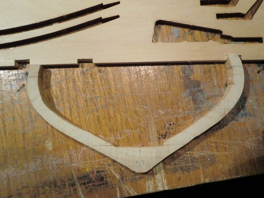
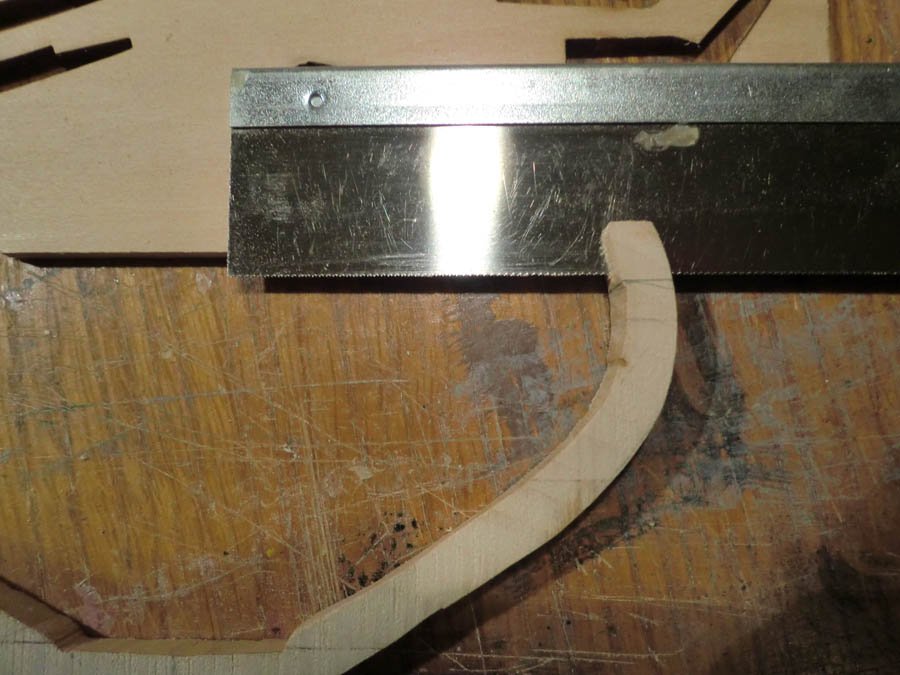
Here is the mostly complete stern piece. I think I did a bit more carving after this, but it is pretty close here. Compare to the rough shape supplied in the kit shown above. I did deviate a bit from the kit here.....I cut a carefully shaped, symmetrical transom piece from 1/16th inch thick basswood and attached that to the bottom of the carved stern piece, rather than trying to get the shape just by carving it. Can't really see it on this picture though.
And here it is attached to the keel and last frame:
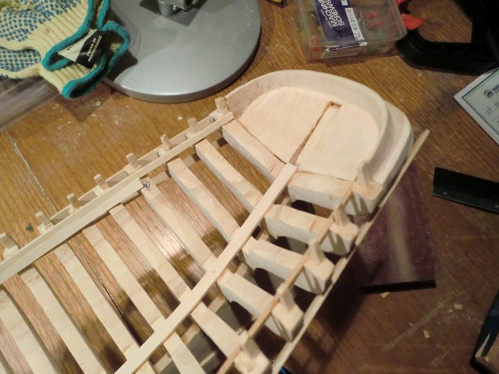
And finally, this picture shows the keelson (across the bottom of the frames) and the starboard sheer clamp being clamped on. The sheer clamp is made of two pieces...the lower one was supposed to go all the way to the stern but it was difficult to twist in place and seemed a bit pointless so I ended it on the fourth to last frame. I still need to do the second piece of the sheer clamp on the port side, then there are two "bilge clamps" to be put in, one on each side, half way between the keelson and the sheer clamp. Once I have those on, the frame should be more solid and I will likely do a bit more fairing of the outside of the frame, as well as trimming the tops of some of the frames to make sure every thing is level (i.e. some of the tops of the frames stick up slightly from the top edge of the sheer clamp), and the tops of the timberheads are not all perfectly even. Then it is on to making the deck beams.
- modlerbob, Duanelaker, coxswain and 5 others
-
8
-
I continue to enjoy watching this build. Very impressive progress.
But I am really posting to compliment the HDR eclipse photo in your blog....one of the best I have seen!
- thibaultron, jablackwell and Canute
-
3
-
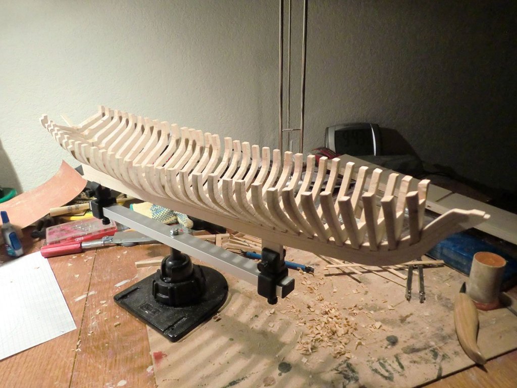
So I have now glued all the frames into the keel. I felt like I spent a lot of time shaping and faring the frames, but now wonder if I should have spent more time doing so, as there are a few zigs and zags and wobbles in the hull, though nothing too bad, I think. I am hoping that as I glue in the lengthwise stringers (keelson, bilge clamp, sheer clamp) that will help to even things out. I might also have to do some shaping of the top part of the frame where it goes from full size to one quarter size to form the timberheads. I generally cut those parallel to the water line but the ones for and aft really should have been angled a bit. None of it is a disaster, but it may make things a bit tricky and take a bit of extra time. The frames are pretty springy and flexible, so doing much cutting or sanding on the frames now is a bit awkward, and can easily lead to the frame snapping (don't ask how I know). Here are two pictures of the current state:
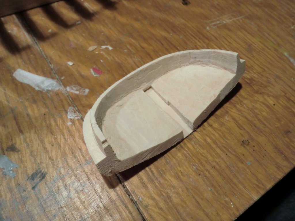
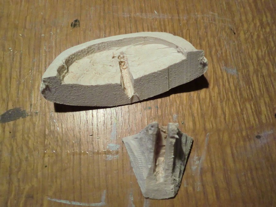
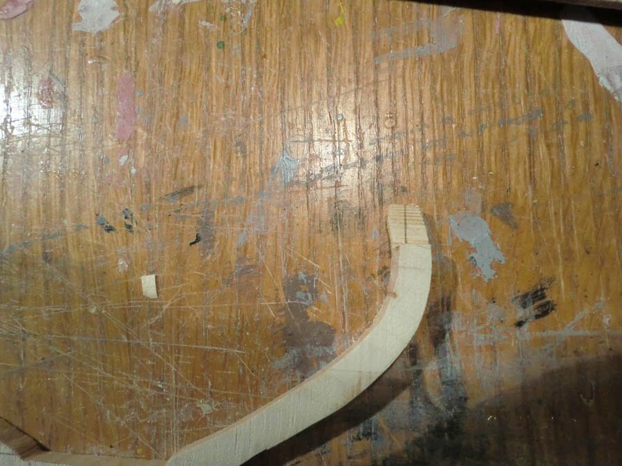
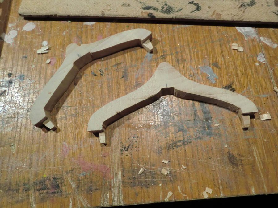
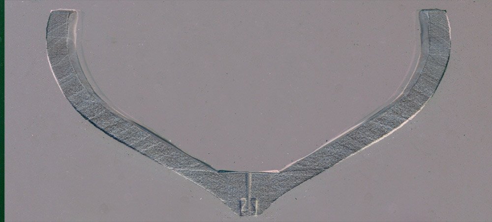
Next up is working on shaping the bow filler block and the stern piece/transom. The kit provided these pieces carved very roughly into shape. The pictures below are pretty much what they looked like coming out of the box.....at this point I have done only a little work cleaning up the slots that fit on the stem and stern parts of the keel.
For some reason, the bass wood used for these pieces seems to be unusually hard, only making it more difficult to work with. On top of that, the plans and pictures only give a rough idea of what these should look like, especially for the bow piece. On the stern, the top of the carved piece is pretty flat (parallel to waterline) but the plans show the back of it kicking up quite a bit, so that is a bit of a mystery. I guess I'll just wing it and see what happens.
And for the curious....my log shows that I have worked about 55 hours on this kit so far.
-
Thanks for the likes and follows. Kevin, I have watched some of your videos.
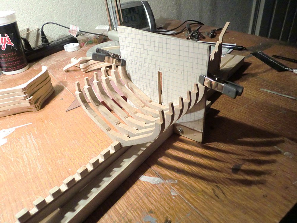
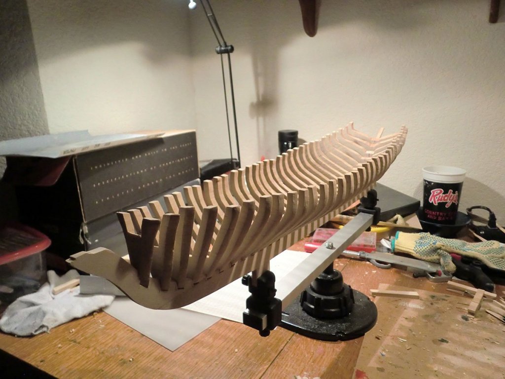
I've created my jig for holding the keel and lining up the frames, and have started to glue the frames in. For some reason the instructions suggested starting in the middle, and so I did. Here's an image showing the first few frames glued in. It is a bit nerve-wracking, even with the jig, wondering if things are lined up right and even from side to side.
- Duanelaker, Papa, GuntherMT and 3 others
-
6
-
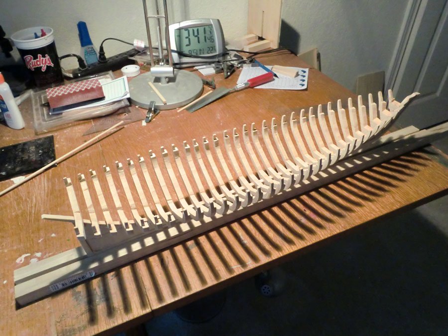
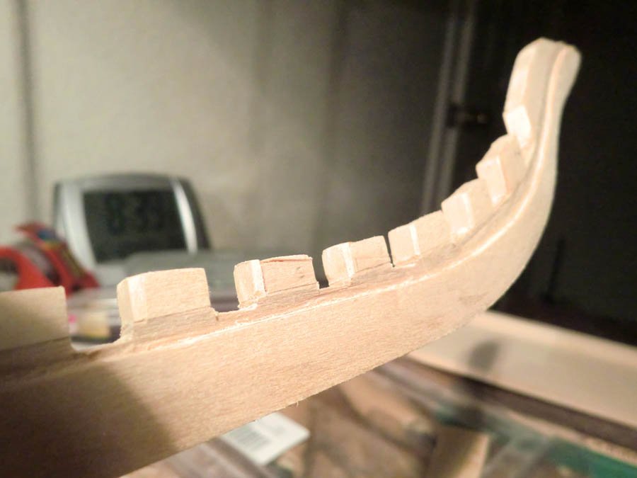
I have continued to cut the timberheads/bulwark stanchions from the tops of the frames, and have all 32 frames done now. I did not exactly follow the recommended order in the instructions; here's how I did it.
1. Marked all frames to indicate the height of the stanchion/depth of the cut down from the top.
2. Used a scrap of 1/8th" basswood from an earlier project to create a simple jig of sorts. I cut a couple notches in it to help hold the frames in place as I made the cut down from the top. Then, holding the frame and basswood jig against the table, and the saw against the jig, I cut down from the top of the frame to the mark. I made sure to always have the "aft" side of the frame down against the table (well, not really....I made that mistake once, and after that I made sure to always have the aft side down!)
3. I then cut down on my mark to free that top half bit of the frame, and made another mark showing the width of the stanchion.
4. Then I cut on the new mark, and made one last small horizontal cut to free the remaining bit of wood. On some frames I did a little bit of additional shaping or clean up using the carving knife or sandpaper.
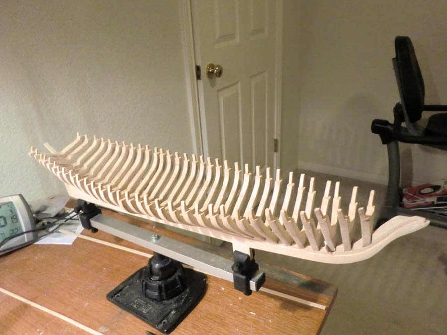
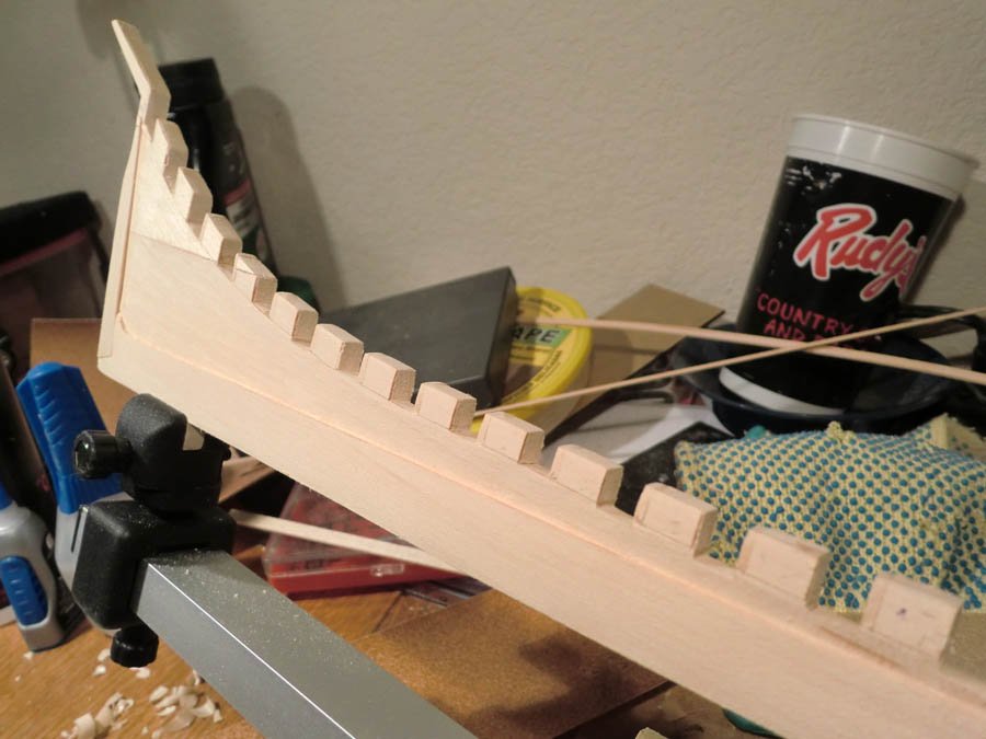
And here is the end result....the frames are all still just "dry-fit" into the keel so are not all lined up correctly. Finally I am just about ready to glue the frames to the keel. I need to get some supplies for a "framing jig" that I have a mental image of, to help me get everything square and true.
- Duanelaker, coxswain, russ and 6 others
-
9
-
Cool build. I've seen this kit on the website and been intrigued by it, but do not have it. Your progress all looks really good, but I am most impressed by the prop. Seems it would be tricky to get it symmetrical but you seem to have accomplished that. Following along...
- thibaultron, CDW, Canute and 3 others
-
6
-
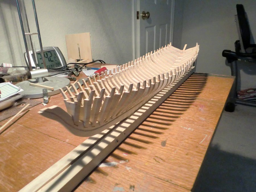
Unsurprisingly, progress has slowed. Since the last update, the main thing I have done is carve the rabbet from the keel. I followed that by doing more fitting of the frames. I carved the rabbet along the lines marked on the keel, but in the middle of the boat especially, the distance from the bearding line to the rabbet line seems to be too great. The bottom most plank would not lie anywhere close to flat against the frames. I have been compensating for that by deepening the notches in the keel that the frames sit in. I probably have more work to do there to make sure things are all even.
I am also not real happy with the shape of the last 7 frames, where the bulwark notches in from the rest of the frame. The notch should be more progressive than it is...instead it is about the same depth on all the frames. I may need to glue on some wood there to correct this. Meanwhile, I have started marking and carving the tops of the frames to form the timerheads. I have just the last two frames done.
I still need to decide how much, if any, of the planking and decking I am going to leave off to expose the frames. I am leaning toward "none" but if I do decide to leave some off, I want to make sure the visible frames are finished nicely, and perhaps even detailed to appear to be made from multiple pieces.
Below are two pictures of the rabbet and one of the timberheads carved on the last two frames.
- Duanelaker, Nirvana, Elia and 2 others
-
5
-
Dry Fitting the Frames
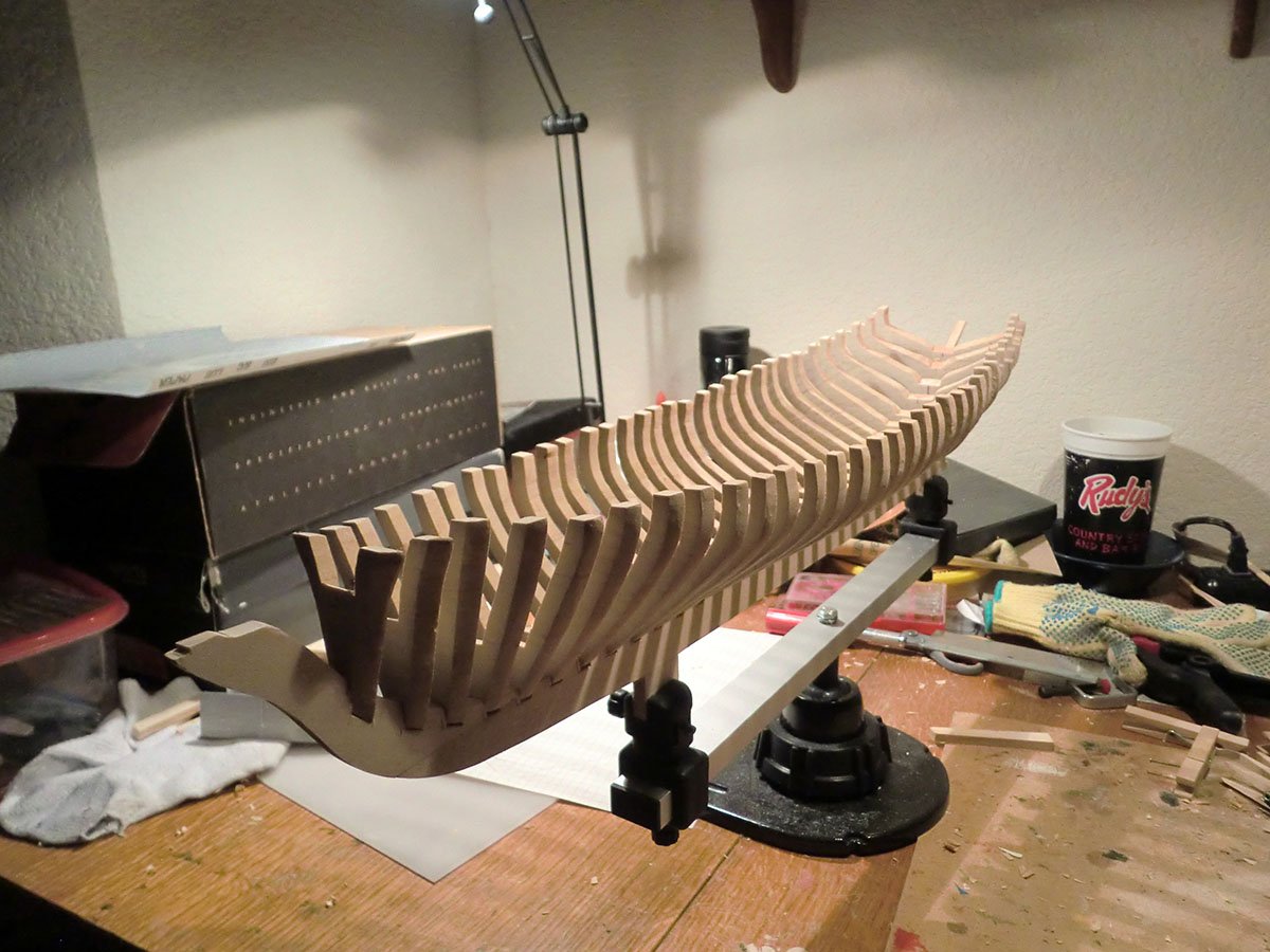
Yay, it is starting to look like something. I pretty much have the frames to their final shape inside and out (minus carving out the timberheads/bulwarks stanchions from the top 3/8ths of an inch or so), and have press-fit them into the notches in the keel to get an idea of what it will look like. Obviously when I glue them in I will be much more careful about getting them straight and level. I still need to do some work on the keel before that, such as carving the rabbet and tapering the keel a bit.
- Elia, russ, Tim Curtis and 6 others
-
9
-
I mentioned earlier trying to scan the frames and use photoshop to help show where the frames were not symmetrical. Now that I am farther along, I tried this again, and improved my technique to the point where it is useful, so I thought I'd explain here. This would probably be most useful to the scratch builders out there; I presume most kits with laser-cut bulkheads would be pretty symmetrical out of the box. This works best for the frames in the middle...the end frames with a lot of bevel get a little bit more difficult to see what is going on. Even in my image below, you can see some ghosting on the inside top section of the frame from the bevel there. When there is a lot of bevel, that ghosting can make this technique more difficult.
Here's what I do....I assume anyone continuing to read has some knowledge of photoshop
")
1. Scan the frame. I used a piece of green plastic behind it to provide better contrast.
2. Load the scanned image in photoshop and use the crop/rotate tool to ensure the image of the frame is perfectly level. I compare the tops of the frame with the grid lines that the crop/rotate tool overlays on the image.
3. Duplicate the background layer and select that duplicate (top) layer as the current layer
4. Turn the top layer into a negative...Image->Adjustments->Invert
5. Reduce the opacity of the top layer. If you set it at exactly 50% your image will be a solid gray.
6. Flip the top layer....Image->Transform->Flip Horizontal. Sometimes at this step or the next one you realize the frame may not have been quite level. Go back to step 2

7. Select the Mover tool and use the left and right arrows to move the top later so it lines up as closely as possible with the bottom layer.
The resulting image looks like the one below. Any brighter and darker areas are places where the frame does not match between the two sides (The bright and dark areas are mirror image of each other). The bright areas are the parts of the frame that are excess compared to the other side....i.e. trim off the bright areas to get the frame perfectly symmetrical. You can see with this frame I did a pretty good job with the graph paper technique. Just a little sanding or shaving would get it perfect. If I was really particular about this, I could scan the other side of the frame and repeat the process.
Hope this makes sense, and hope it is useful to someone out there.
-
Thanks for the likes and follow.
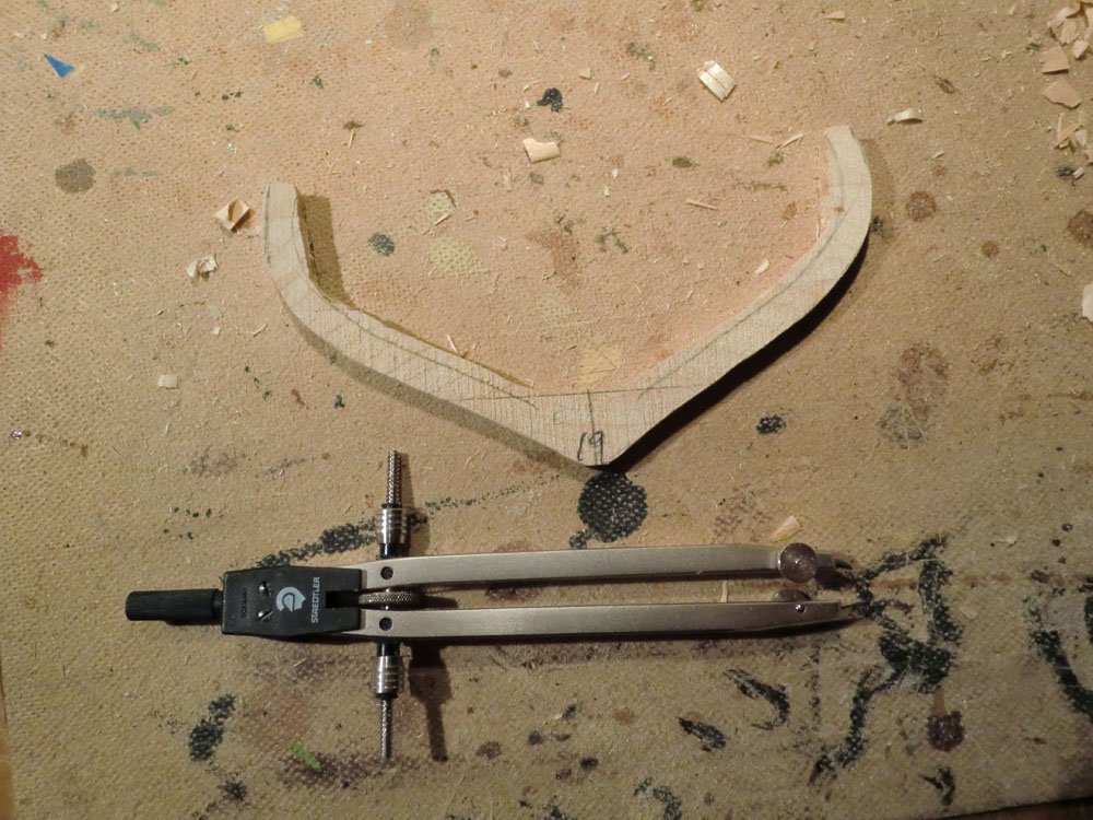
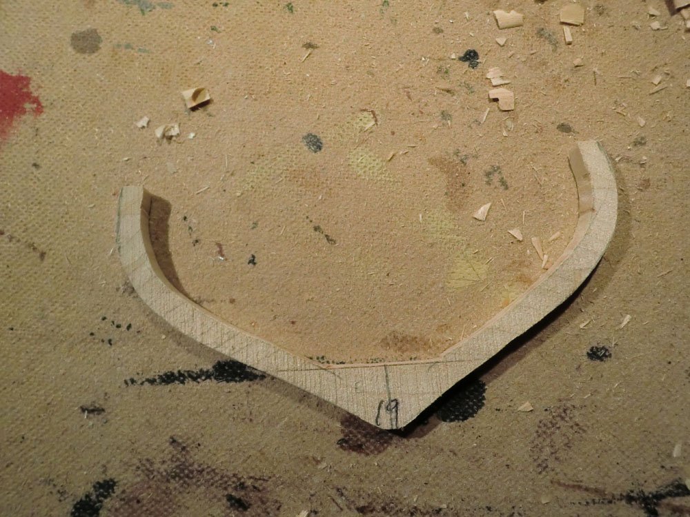
Here's a bit more detail about my current step. I have the outer profile of the frames pretty well done now, I think. I have been going through them again, comparing frame "N" to frame "N-1" and frame "N+1" and tweaking as needed. I then drag the point of a drafting compass along the outer edge of the frame to draw a line to define the inner edge, and repeat that on the other side of the frame. That provides a guide for carving the frame down to size, and to make them all consistent width. The first picture below shows the line drawn on the rough frame; the second is after the frame has been carved down to the line. I have this done on 20 of the 32 frames. After that, final sanding of the frames and carving the timberheads at the tops of the frames.
-
Progress So Far
As mentioned above, I have worked about 30 hours so far, including spending a fair amount of time reading through the instructions a couple times.
I cut out and glued together the keel, stem, and stern pieces, and I made my first mistake. I cut the notches in the top of the keep trusting the lines, instead of making sure the notches were the right size for the frames. They are all too large, so I have added a shim piece to every notch to narrow it. As for the tabs on the bottom of the keel....the photos in the instructions show all the extra wood at the bottom of the keel left in place until well into the building of the hull. I thought it would be difficult to cut off at that time. But the bottom of that piece of wood does provide a reference for "level" and reference to which the frames are perpendicular. I compromised and left those two tabs to give that reference and to give something to hold on to, but they will also be easier to remove when the time comes.
Otherwise, all the time has been spent on shaping the frames. The pre-cut and pre-bevelled frames were not necessarily symmetrical, and they were too thick from the outside toward the center line. I spent a lot of time carving them to shape and trying to make them symmetrical. At times I felt like I was turning the 1/48th scale model to 1/50th! To make the frames symmetrical, I attempted some techniques involving scanning them into the computer and flipping the image in Photoshop. But it was easier to just trace the frame on graph paper and count squares. I have made several iterations of trying to get them symmetrical and trying to get frame N to flow nicely to frame N+1, and trying to get the shape to match the lines on the plan. Once I felt like the outer shape of the frames was good, I started working on making them constant thickness by carving away at the inside. I have done the latter task on about a third of the 32 frames. After that, the timberheads are to be carved out of the top little bit of each frame. Below are several more pictures of the frames during this process. And that's where I stand today on this project.
-
Decisions, Decisions
There are a few other decisions I'll need to make as the build progresses....
1. The kit is supposed to be a more realistic plank-on-frame kit, though as I understand it, the exact construction of America is unknown. But it sort of begs to have some of the planking and decking left off to show the work that was done on the inner structure. But I am more of a "complete looking model" fan. And, the kit makes no provision for the sub-deck.....if one were to leave some of the planking and decking off, it seems like the subdeck should be represented as well. For now I am leaning toward completely planking and decking the boat but we'll see.
2. The other decision is how to finish the model. I generally like the looks of models that are left with a natural wood finish...stain or oil rub or whatever...but also like a more realistic finish. I see some of the builders of the Mamoli kit used actual copper plates on the hull. The Bluejacket instructions advise against that, indicating that the makers would have tried to make the hull as smooth as possible with tiny gaps between the plates and no protruding fasteners, so any embossed plates that have such features are out of scale. But real copper would look nice. I suspect I will wait until I see how well the planking goes and at that point decide if I need to hide any mistakes with paint or copper.
3. As mentioned, I may or may not use the supplied blocks and rigging line. I also will need to decide how to rig, but the common thing seems to be the unrealistic but more pleasing method of having the spars positioned as if sails were present, with the rigging providing something of an outline of the profile of the sails. Again, plenty of time before I get there.
-
Thoughts On The Kit
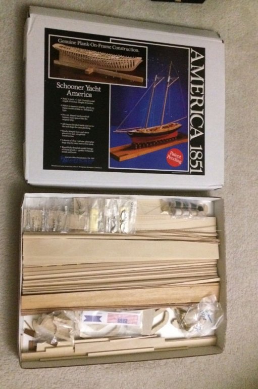
The kit is interesting and appears well made. In the picture above, you can just see bits of a few of the frames. The kit comes with a set of pre-cut frames. They actually carve a hull, slice it like a loaf of bread, and (I presume) make two kits from it, giving each kit every other frame.
The keel, stem, and stern are printed onto one quarter inch thick basswood, but must be cut out, and there are no other laser cut parts. There are pre-carved bow and transom pieces. Overall the quality of the wood seems very good.
The kit also comes with quite a few metal components, both brass and britannia. They look good, but I am unsure about some of them. In particular I am not crazy about the britannia metal blocks instead of wood blocks, though I can see both pros and cons, and the plans do indicate that the blocks were painted white. The brass ring mast hoops also seem questionable. I have plenty of time to decide if I will use them or replace them.
Also the rigging line is black and white, instead of the more traditional tan. Again, I have plenty of time before I decide to use or replace that.
But overall, the kit leaves a good impression.
-
Hi All. This is Gary from Austin, Texas making my first post. I have recently acquired the 1/48th scale America kit from Bluejacket and hope to log its build here. I have been lurking here a bit, very impressed by the knowledge and craftsmanship shown in many of the build logs. And frankly I am a bit intimidated as well. But I did not find any other build logs for the large Bluejacket America model so I hope my efforts add to the community, if only because of that. I have seen several build logs of the Mamoli version, and I am sure I will reference them more in the future.
Over the last many years, I have built a handful of wooden boats and ships. The most ambitious project was Model Expo's Niagara. Sadly while building that I realized two things: 1) I do not enjoy rigging 2) I am more interested in small work or pleasure boats than warships. The Niagara has spent maybe 8 years in my closet with the standing rigging half done while I went on a boat building hiatus.
Then in October, 2015, completely by accident, I drove by Bluejacket's HQ/Store/Gallery in Searsport, Maine while making my way from Boston to Acadia National Park. I made a quick U-turn and stopped in. I guess I left there inspired, as since then I built their Swampscott Dory and their Lobster Boat. Around the beginning of this year I decided to challenge myself a bit and ordered their plank-on-frame America. And yes I realize it requires some rigging, but it is minimal enough that I should get through it!
Don't expect quick progress. I still work full time and have too many other hobbies. I've had the kit for about 2 months and have worked on it less than 30 hours so far. Progress will appear to be quick initially as I'll make posts to summarize those 2 months of work.
But first here is a picture of the freshly opened box when I got the kit:


America by gsdpic - FINISHED - BlueJacket Shipcrafters - 1/48 scale
in - Kit build logs for subjects built from 1851 - 1900
Posted
Deck Beams
Like the hull, the construction of the deck of this model is very much in keeping with plank-on-frame. The kit calls for making a bunch of deck beams that run across the width of the hull, with the planking then placed on top of the beams. In a detail that I suspect will be almost imperceptible on the finished model, the deck is crowned so that the centerline is about an eighth of an inch higher than the edges.
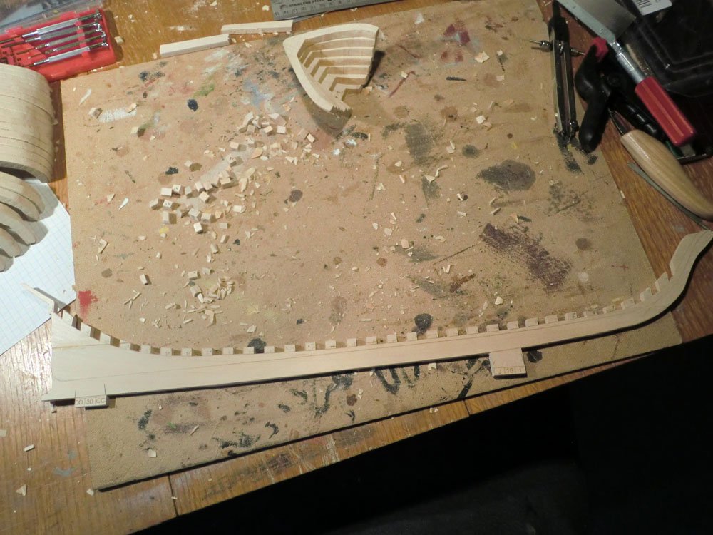
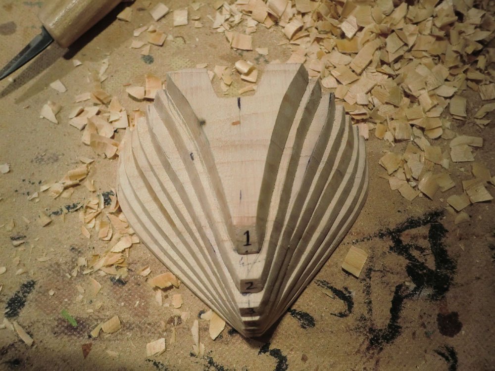
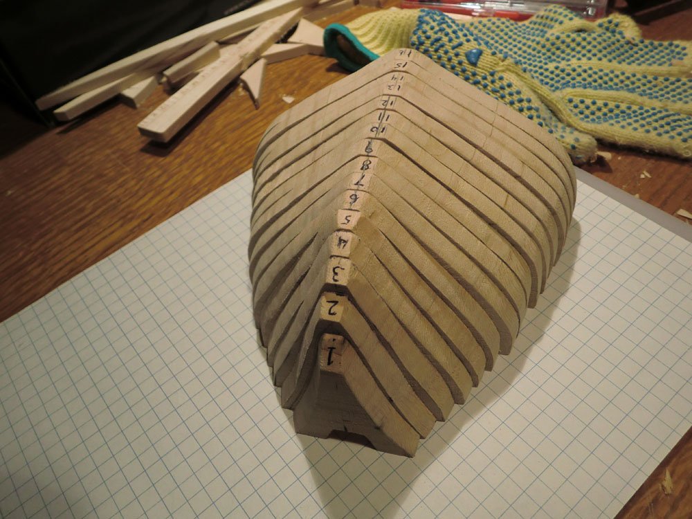
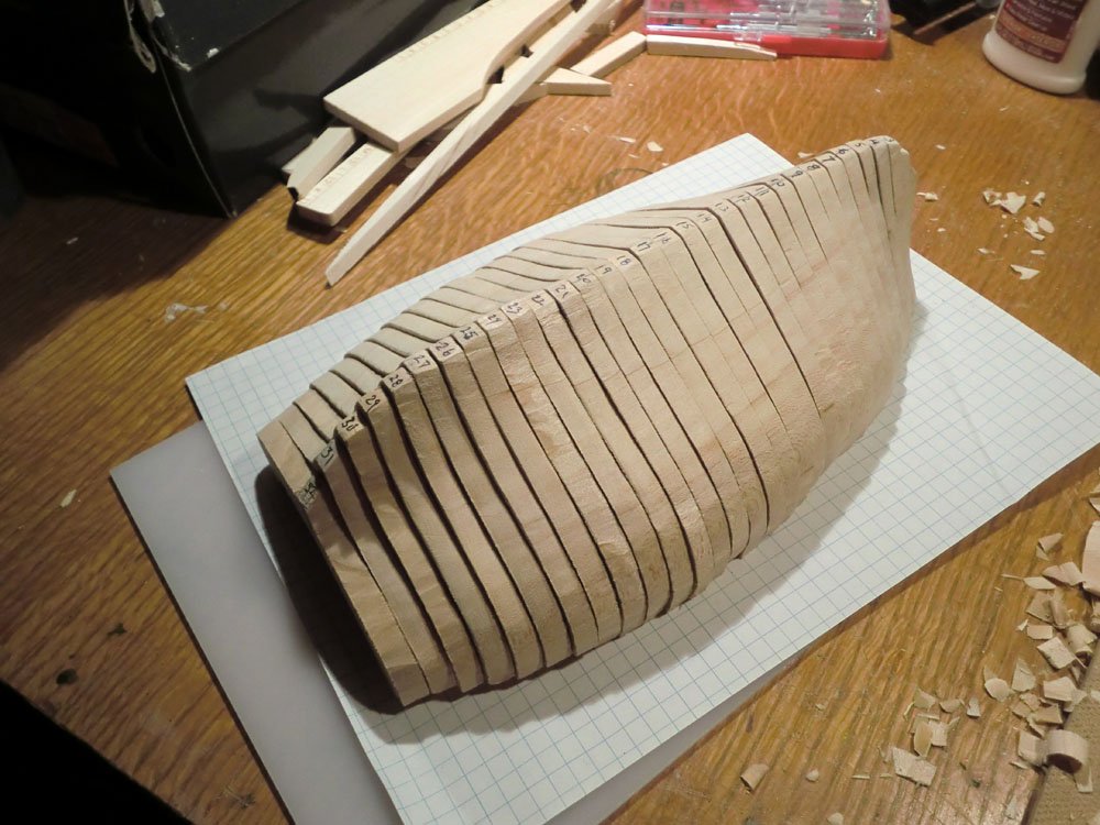
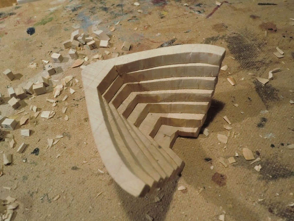
To accomplish this, you first glue edge-to-edge 5 pieces of quarter inch thick basswood, to give a block that is 5.5 inches wide, 10 inches long, and a quarter inch thick. Then using planes, rasps, files, and sandpaper and such, you create the crown on this larger block. Finally, you cut 1/8th inch strips across that block to create the deck beams.
Pictures of this process are shown below. To help, I created a special sanding block that also had the shape of the crown, to try to get the curve consistent along the block of wood and from side to side. I also drew a couple reference marks on the block that may help later in construction.
The initial 10x5.5x1/4 block and some tools...
Initial crown on one side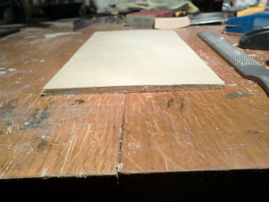
Both sides crowned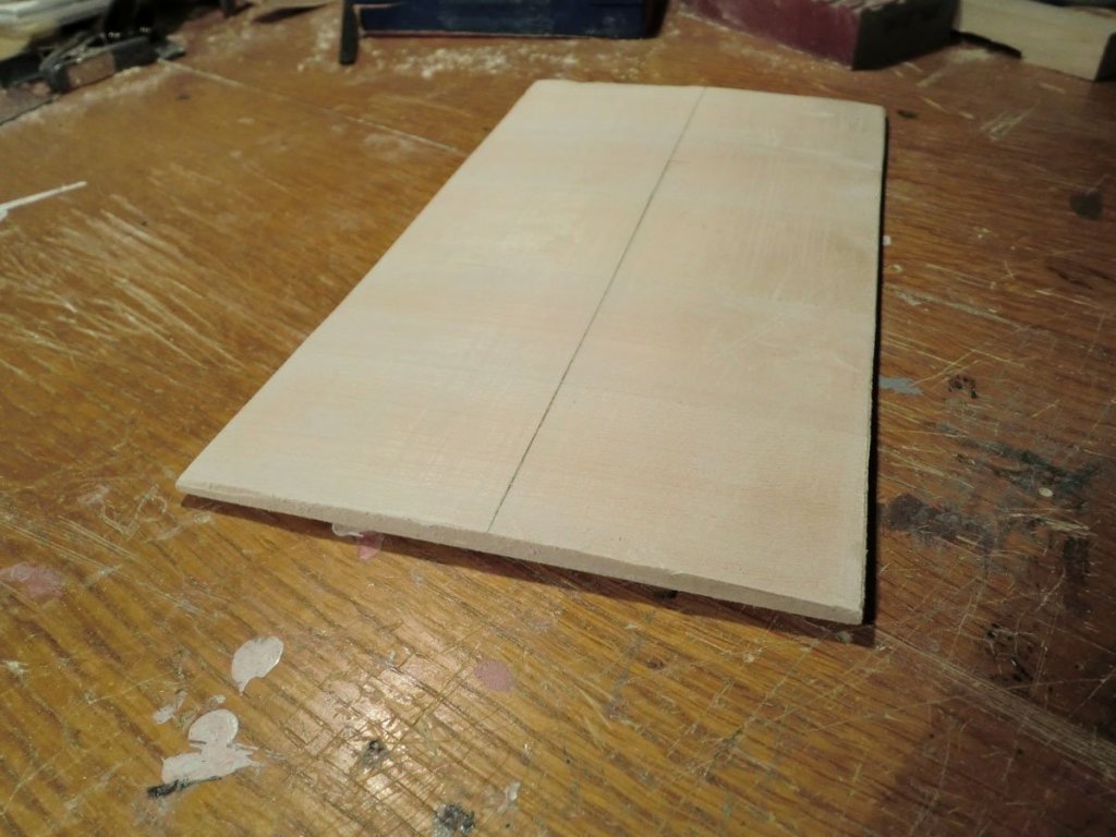
Special sanding block
Block with a few beams cut from it. Clearly I'll need to clean these up a bit with some sandpaper.
I suspect that my block may not have quite as much of a crown as intended, but I guess I got tired of shaping it and anxious to cut the beams. Either way, like I said, I don't think this feature will really be noticeable on the finished model. The booklet calls for cutting about 40 beams....I have 15 cut now. I am using a scroll saw with a guide fence, which is probably not optimal, but is what I have available.