


Heronguy
-
Posts
863 -
Joined
-
Last visited
Content Type
Profiles
Forums
Gallery
Events
Posts posted by Heronguy
-
-
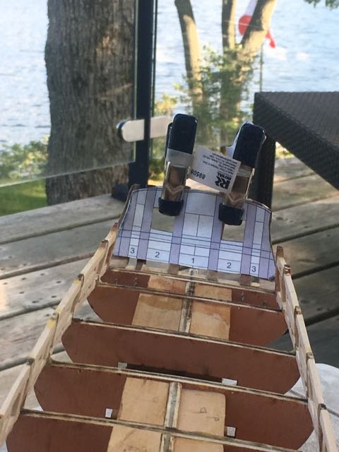
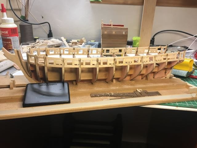
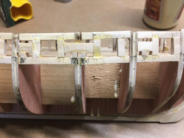
Installing the gunport framing proceeded with only minor issues. The 1st time I attached the template it was too high but I caught it using the cannon cutout.
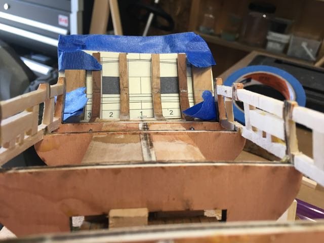
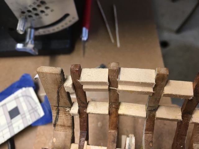
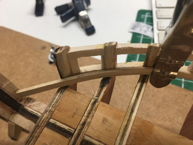
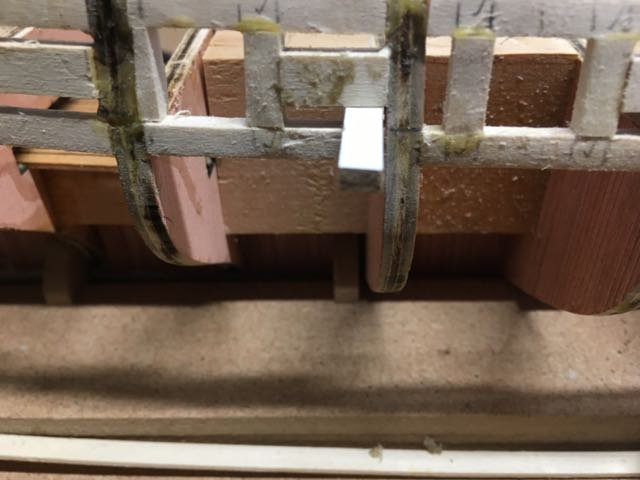
I wasn't sure from the instructions or other build logs how to frame the lintels - the instructions suggest glueing 2 3/16"x1/4" pieces together. I ended up installing them in "stair-step" fashion so that the top of the gunport would be parallel (bow to stern axis) with the sill.
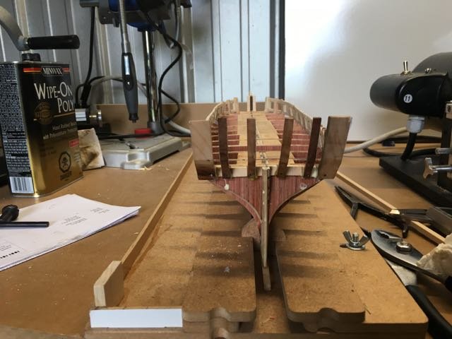
I trimmed the template to get the top of the transom marked on the stern.
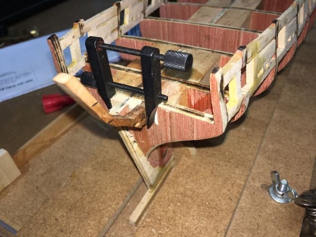
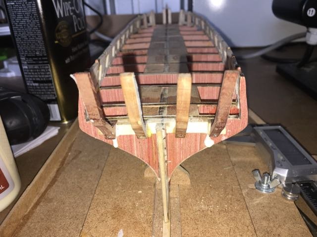
As I hoped the use of hardwood stern frames, pinned to the hull, proved to be very robust. OI had no mishaps sanding the stern and sanding the hardwood did not prove to be at all difficult. I did have some problems with the glue joints for the filler blocks holding. When I first received my second-hand ship modelling library I decided to start reading "Plank-on Frame-Models" by Harold Undersell. Early in the volume he writes:
" ... I never leave anything to adhesive, but ever single item, no matter how small, is always pinned or dowelled. That is one of my pet obsessions."
At the time I thought that quite quaint and old-fashioned. I'm reconsidering - perhaps it will become one of my obsessions given the experience I'm accumulating!
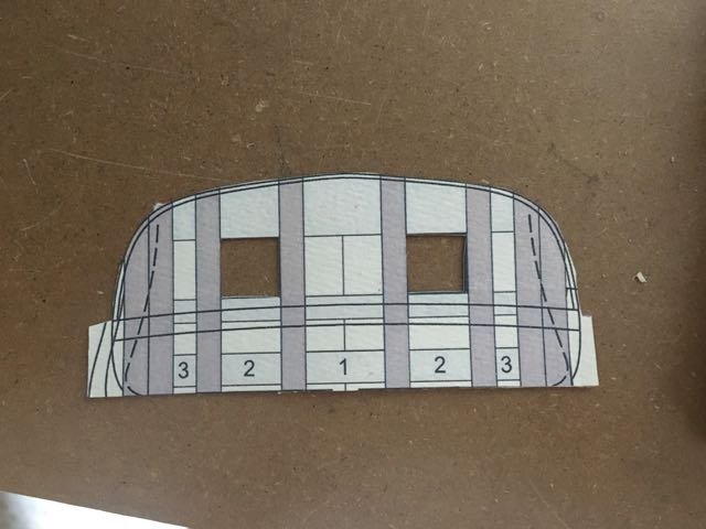
I trimmed the template again to the planking curve and compared it to the marks that I made by using a plank to give a fair run at the stern as outlined in the instructions.
Some more sanding and I'm almost there!
- Tigersteve, David Lester, piter56 and 6 others
-
 9
9
-
Enjoy your summer Derek. It's great to spend time with your kids while they're young enough to enjoy it! The ships will be there in the fall.
-
Joe,
The log is hiding in Scratch Builds - I had to hunt to find it too.
-
4 hours ago, reklein said:
Doug, I'd recommend just sanding the exterior first. Then plank the exterior before sanding the interior. After planking the structure is very strong. Specially on the stern where it is really flimsy until you've got planking on it.
Thanks for the suggestion Bill. We'll see how mine hold up on the exterior sanding - I'm hoping they'll be strong.
-
Hi hamilton, I read of your injury. I'm scarred on my hands from my various encounters with the blades. I probably should stay away from scalpels - sounds like they cut deep!
I'm just at the point to starting to sand my hardwood stern frames - I'll soon know whether the strength vs sandability trade-off pays off!
-
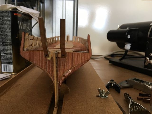
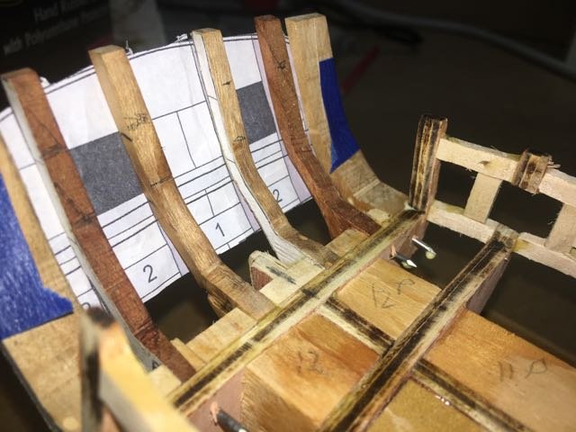
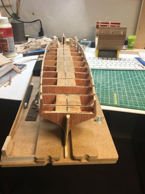
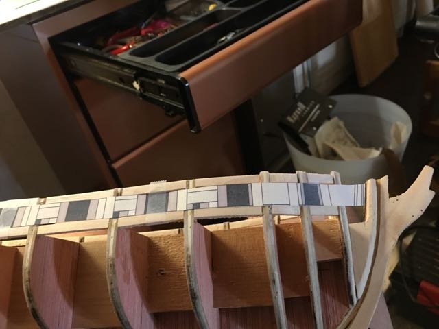
Chapter 4 - stern framing
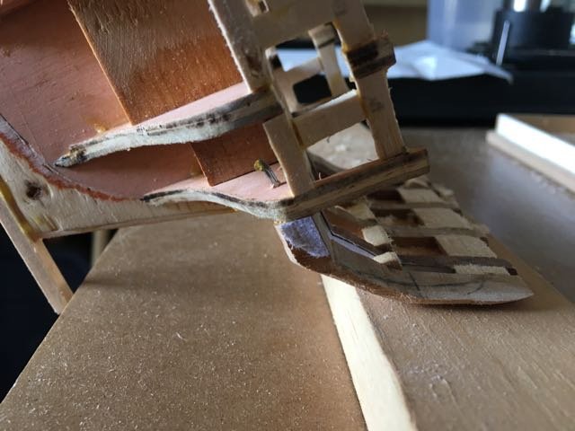
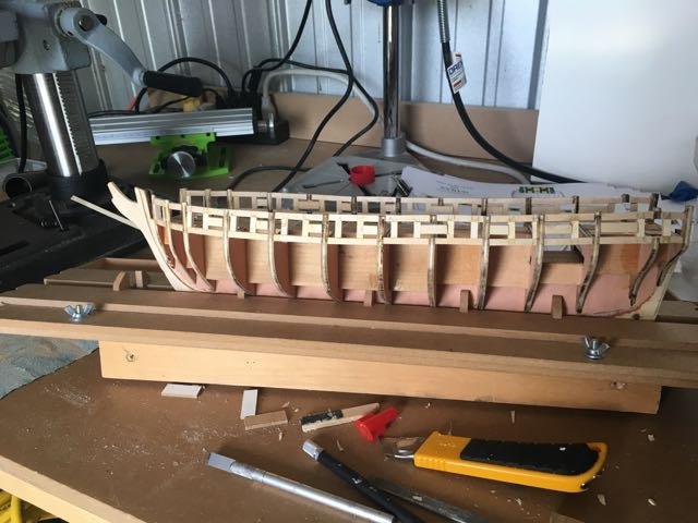
I'm looking forward to seeing how the hardwood stern frames work out. Because of all the comments about the fragility of the structure while it is being built I decided to pin the frames as well as gluing them.
I used a drill press and a 1/16" bit to drill through the frame. Then I clamped it to the filler block and ned a hand drill to drill a continuation of the hole through the bulkhead. the pin was a finishing nail trimmed to length.
An added bonus (besides the expected strength) is that it hold the frame in position very nicely while the glue sets.
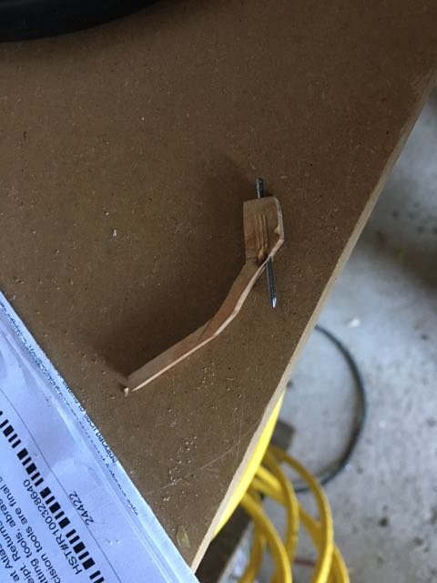
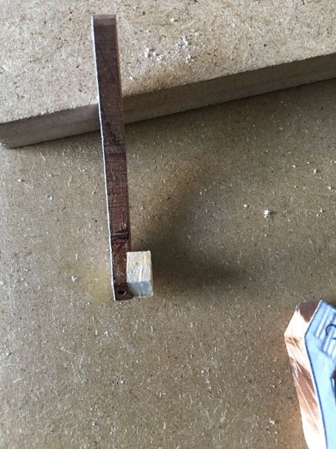
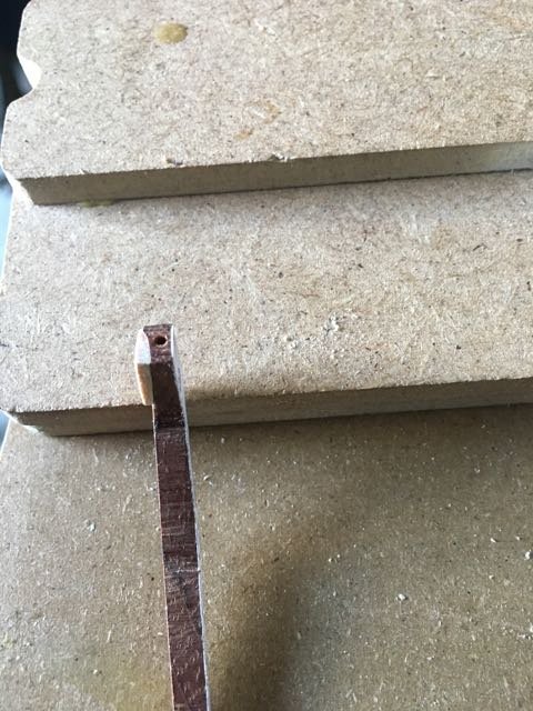
When I got to the 'B' frame I discovered that I must have damaged it on the sander because the bottom cornet was thinned down.
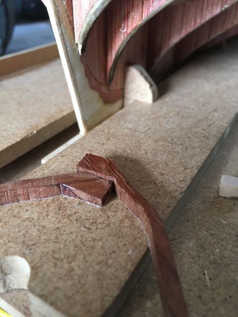
Two simple choices - make a new one or fix this one. The fix was easiest and it turned out just fine.
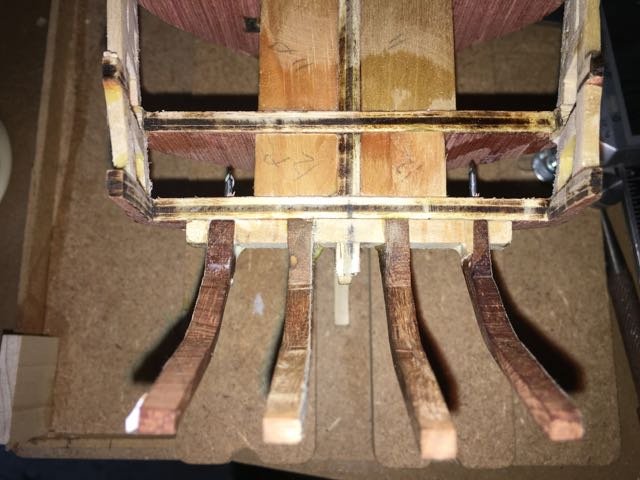
Added the 'C' frames which I'd cut double width when I fabricated them.
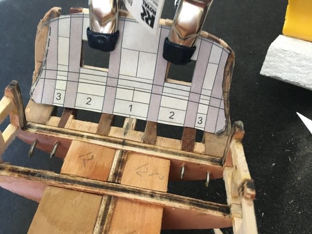
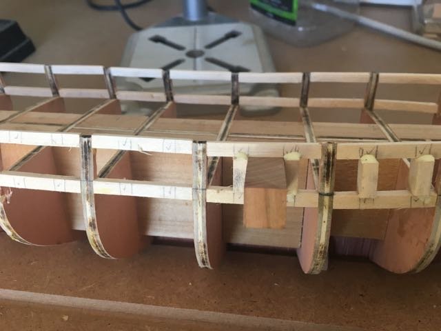
The template is attached to the frames so the gunport sills can be located.
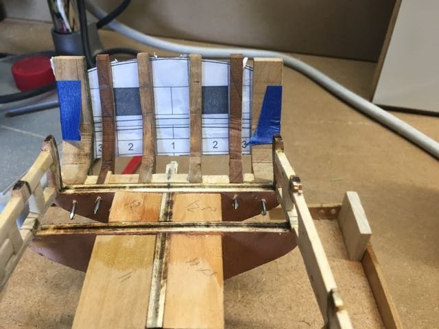
The sills are attached
-
When I see prices like those on not-rare books I always figure that the seller doesn't actually have a copy. They put up a crazy value to keep a listing and if anyone actually pays for one then they have a lot of margin to pry one out of the library of someone willing to sell. Just my theory but I'm certainly not going to try to test it out! Although maybe I'd sell my copy for $195 if someone were wealthy enough to offer it!!!
Good hunting Michael - if I stumble across a good price I'll let you know.
-
-
Thanks Don, That clears up my question. I didn't realize there was also a starboard stern view - just couldn't see how you knew from the single view!
- EJ_L, Canute, popeye the sailor and 1 other
-
4
-
-
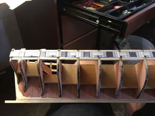
Bloody but unbowed I continue with the battle - sorry a bit melodramatic!
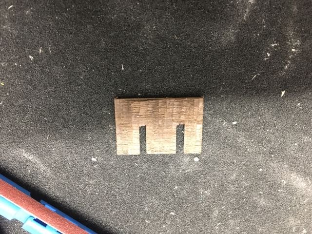
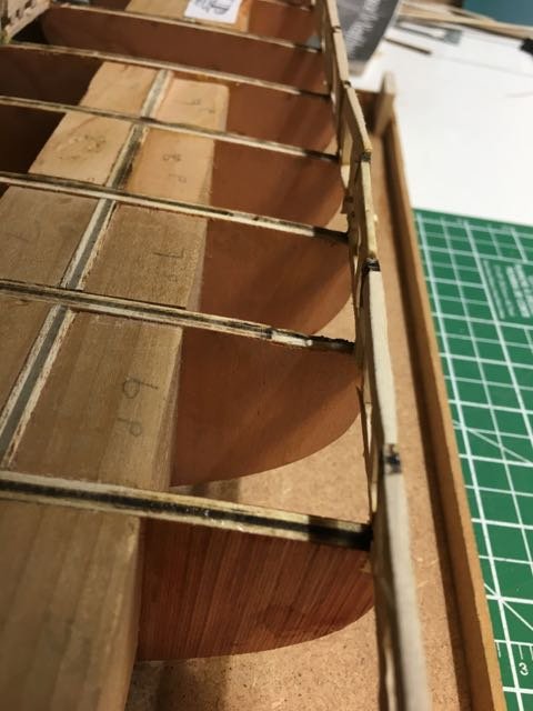
Back to fairing the bulwarks structures. I cut a 1/8" slot and a 3/32" slot in a piece of scrap to gauge the thickness of the sills and lintels. It made it easy to find high spots that needed a bit more sanding.
And after some time I got to this stage.
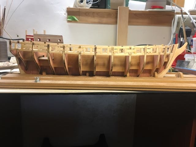
Checked the fairing at deck level and the top of the bulwarks with a pre-bent planking strip.
The photo above convinced me to take a bit more off the 1st bulkhead extension - it lies closer now.
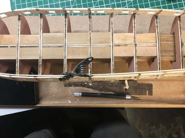
I believe everything is now within reasonable tolerances so I am ready to go on.
- _SalD_, reklein, CaptainSteve and 9 others
-
12
-
Oops - Missed that sentence. It always amazes me that I can read things 3 or 4 times and yet miss information.
Edit: When I checked the instructions I also found advice on page 7 - the bottom photo where he suggests inner bulkhead extensions to be faired. I guess we can have it either way - which is our prerogative anyways!
-
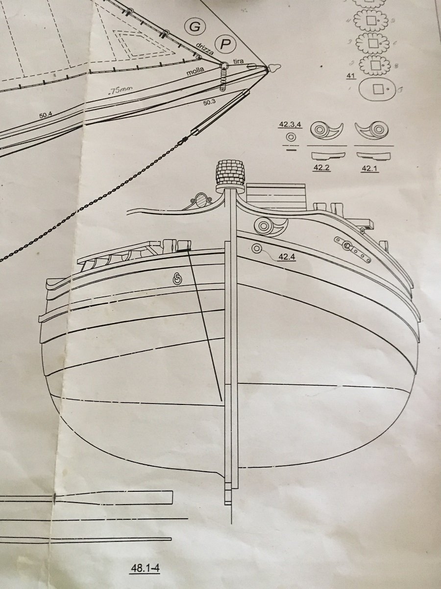
On 7/7/2017 at 1:55 PM, donrobinson said:
It was brought to my attention by a good friend of mine, Zoran, that I did the rigging on the rudder a little wrong. I went back to the plans and sure enough what I have done is not the same as what is shown
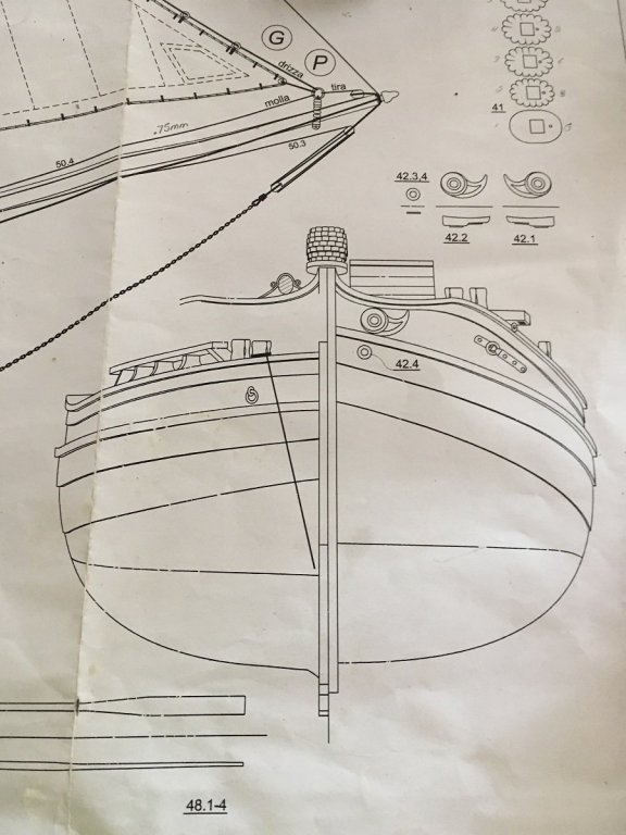

As you can see the plans show only a rope on the port side tied to the rudder and on mine I have blocking on both sides. Now I know my way is wrong and not historically correct, however, I'm thinking in real life this rudder is almost 17 feet long, 4 feet at it's widest point and 6 inches thick. Given these dimensions this rudder would have weighed a ton (figure of speech) and raising it in shallow waters would have been some feat of strength. I'm thinking why not give this crew all the advantage possible and let them have a four block system
 Or should it be done the right way? Given the temperature today and this problem I am considering a trip to the refreshment fridge. Please help, or better yet come over for a cool one
Hi Don,
I'm not clear how you tell from the plan that it is intended only to be blocked on one side? Just trying to understand so I can do a better job of interpreting plans myself.
By the way, has anybody mentioned on how terrific your build is?
")
-
A tour de force! Beautifully done E.J.
-
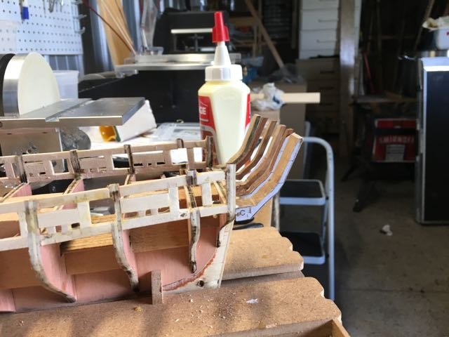
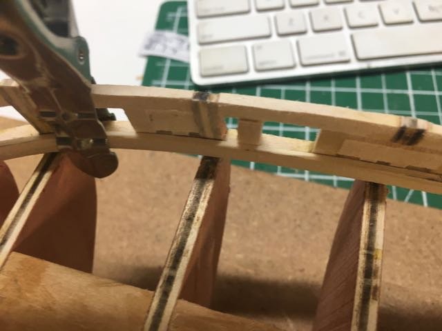
And it was going so well!
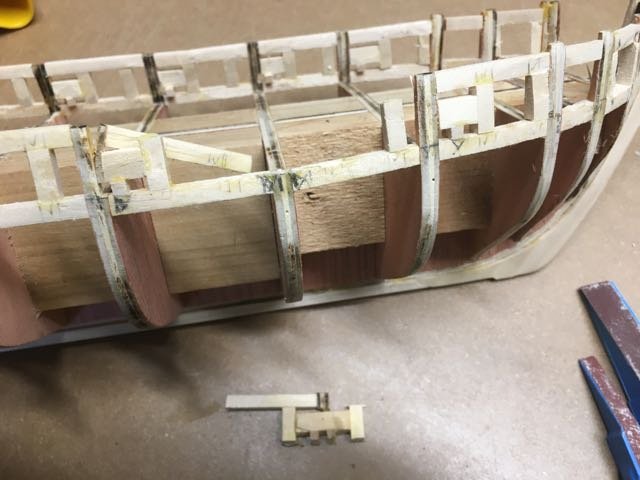
A little too much lateral pressure and part of the framing gave way. This was at a spot where the bulkhead extension had been cut away to a sweep port. It is weak there. It was easy enough to reassemble and fix. The sweep post top is a bit crooked but I think the sweep port itself is fine as I used my 1/8" space to set it.
Then another catastrophe (ok- issue not catastrophe) and when I put it back together the stress on the joint forced it out of alignment. So another fix.
That weak section crumbled again so I replace the assembly by starting with a lintel that spanned over the bulkhead extension that was cut out. This is much stronger and is on a section of the hull (amidships) where there is not much curvature to the bulwarks. This fix has held through the remainder of the fairing process.
And finally a section at the stern gave way! taking with it a bulkhead extension. By this point in the day - most of this happened in one day - I realized that some days would be spent out of the shipyard. Put the tools down and leave the poor model alone.
Fixes yesterday went ok and there haven't been any more failures (yet).
- Ryland Craze, cog, Elijah and 7 others
-
10
-
-
One possible reason for the fairing before installing the sides - to mark the positions for the side timbers you have to trim and tape on the paper templates. You'll want a smooth run on the outer bulwarks for that.
My second reason was that I used a blade and chisel to trim quite a bit of the excess away before sanding. That's easiest when the grain is all the same direction.
I'll be interested to hear other opinions.
- Tigersteve, Jack12477 and Nirvana
-
3
-
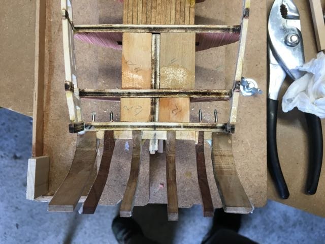
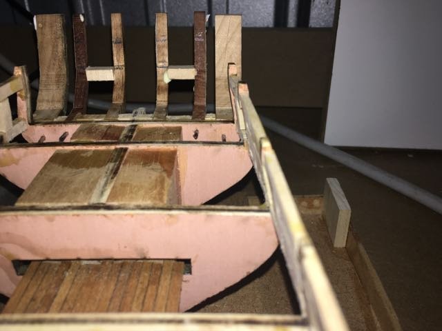
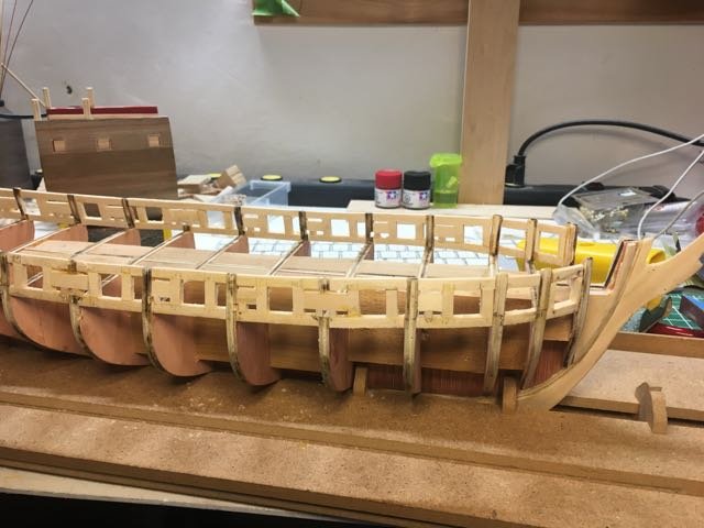
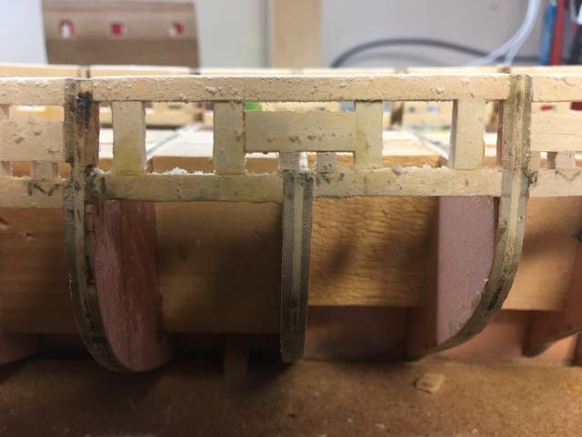
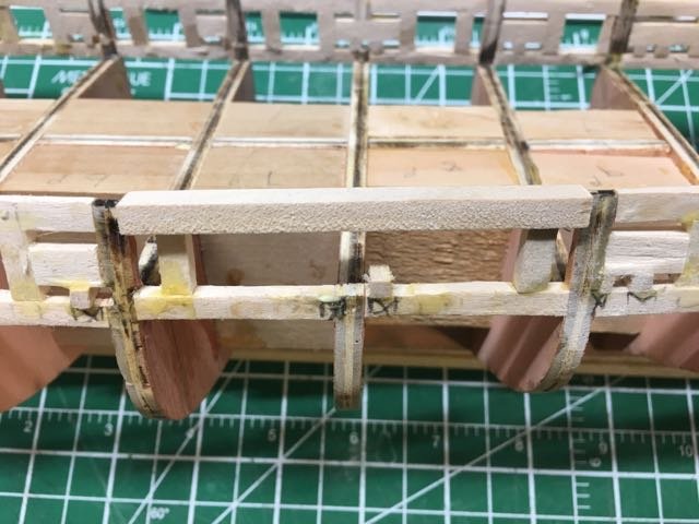
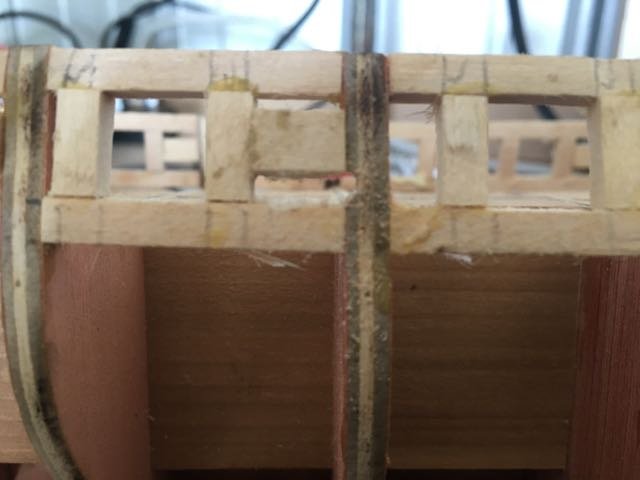
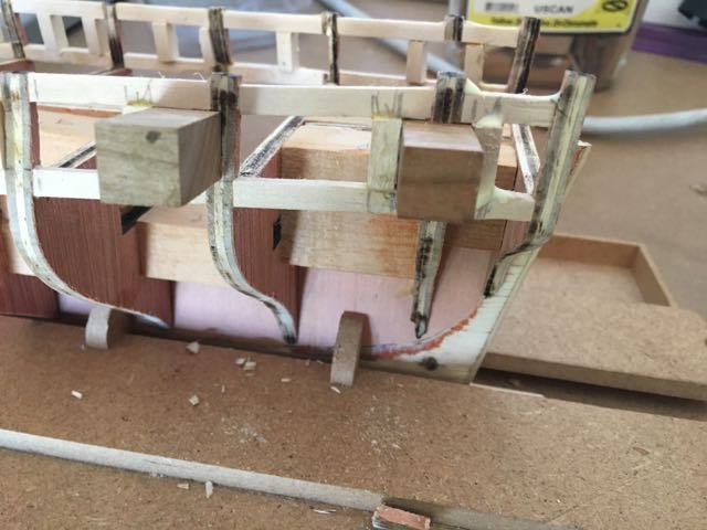
Only 2 steps left. Top of the sweep ports and then the sides. I cut some 1/8" spacers and a 1/8"x1/8" rectangular block for the sides.
Once again the templates are attached to allow the sweep port sides to be located. An alternative might have been to cut a strip of wood that was the gun port spacing (left side of one to the right side of the next), then mark the middle and sided of the sweep port. This little roller then could be used to mark the hull for placement of the sweep port sides. I started doing this later in the process.
There was another pair bulkhead extensions to remove.
as well as a couple of extensions that had to be trimmed out since the sweep ports overlapped with them.
- Elijah, David Lester, CaptainSteve and 6 others
-
9
-
Good to see you Derek.
-
-
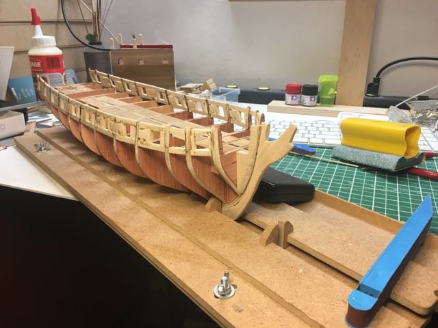
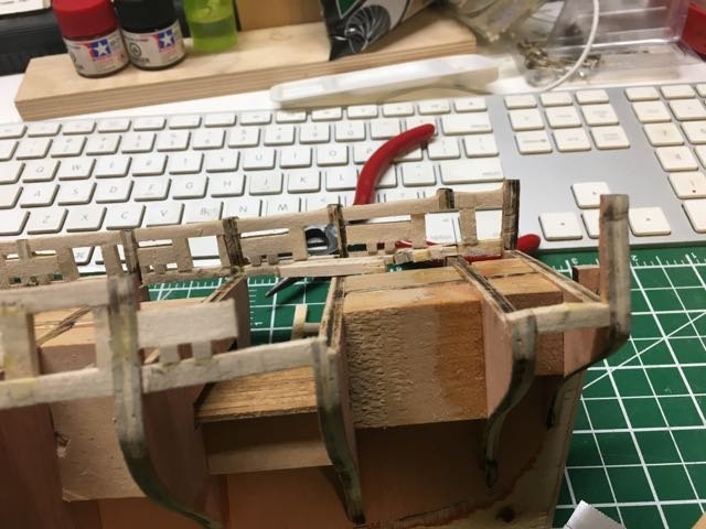
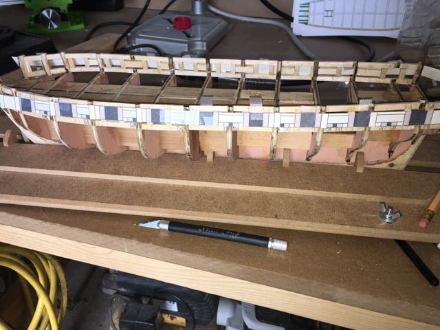
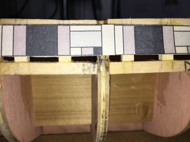
Gun port sides.
Trimmed the templates and taped them back to the hull.
There was a minor discrepancy between the actual bulkhead extensions (other than 26 where we start the alignment) and the position on the template. The instructions say not to worry - so I didn't.
By the time we reached nearer to the bow the discrepancy was about one bulkhead width. I had previously checked the templates, plans etc because other builds had reported much larger discrepancies - so I still didn't worry.
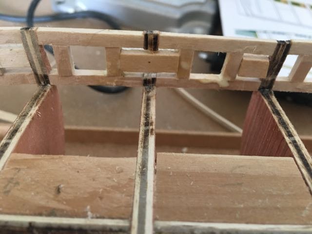
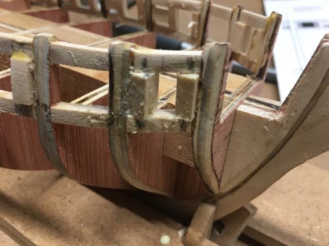
Using my 15/32" block as a guide I positioned act gunport side where marked on the sill and lintel.
Where the gunport opening impinged on a bulkhead extension i used the x-acto saw to cut a small kerf then used a knife and a square file to open it up. I found the use of the block handy for getting the correct angle on the sides of the gunport on the curvier part of the railing. I just eye-balled the block to be perpendicular to the sill.
The bridle port require more dramatic shaping to get the direction correct. I placed the sided flush with the bulkheads to give a good glueing surface, then filed away the excess wood to create the gunport opening.
- David Rice, reklein, cog and 5 others
-
8
-
8 hours ago, donrobinson said:
Wow! That is a beautiful model Dan, I wish I was in that league. Doug adding veneer is a good idea, but the ends of the planks would not match properly would they. I didn't mind the looks of the black paint.
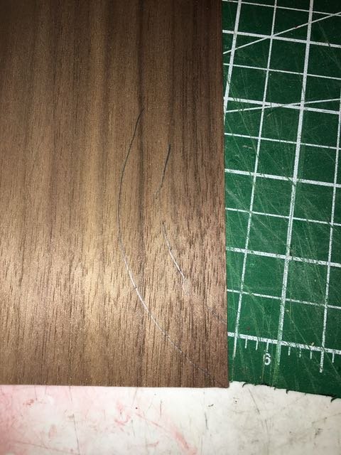
I was also concerned about how easily I would find it to cut the veneer into the horseshoe shape especially as there are a couple of projections (deck support timbers) that possibly wold look best if consistent with the rest of the end (I'm not actually sure of that).
A quick test with a piece of veneer and some black paper to simulate the paint:
Traced the rib (partially)
A couple of vies go the result with just veneer
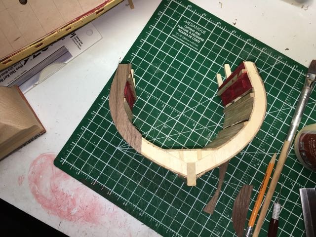
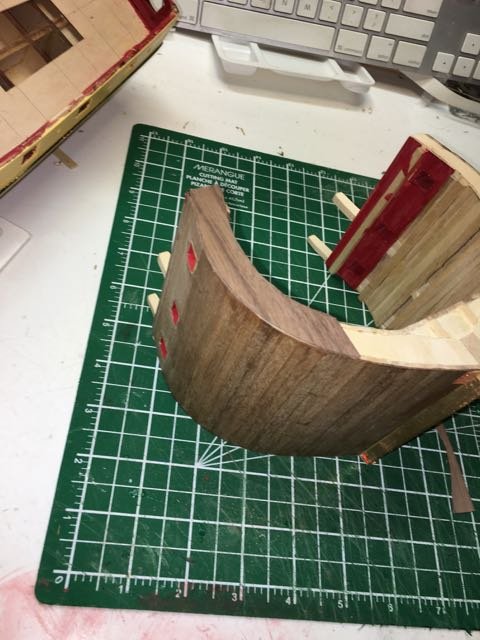
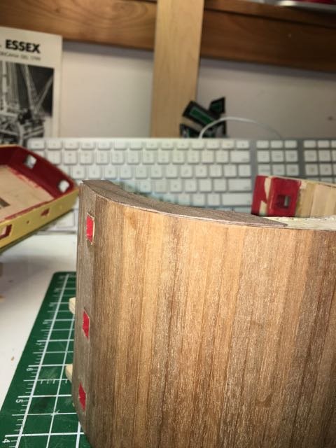
and with the black arm
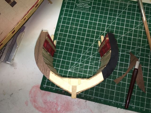
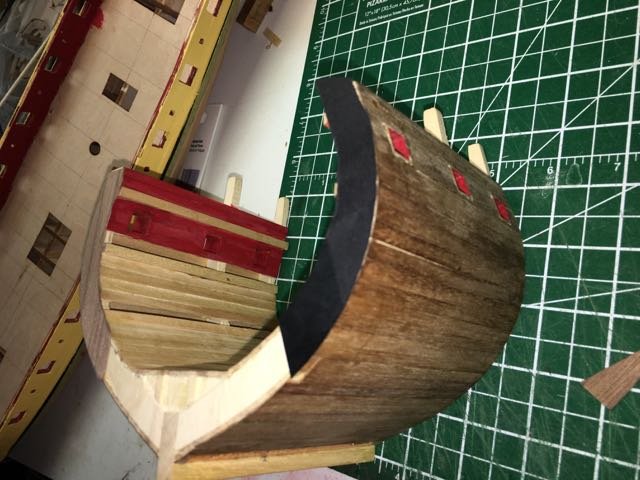
I think the grain in the veneer distracts from the overall appearance - in a sense I think the end of the cross section shouldn't blend with the hull but rather contrast with it. If I paint the ribs I would leave the ends of the planks natural rather than painting over them. How much of a challenge will preventing bleeding of the paint do you think??
- Elijah, popeye the sailor, piter56 and 1 other
-
4
-
2 hours ago, Dan Vad said:
Or you COULD go the other way - build a full model AND a Cross-section of the same to show some of the interior detail that can no longer be seen after hull and deck planking :
Sorry Dan but I'm not in that league! Cool idea though and very impressive!
-
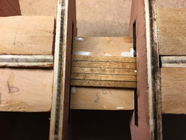
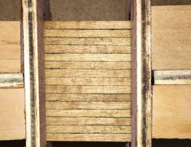
I had to make another short diversion from the instructions as while I was reviewing some other build logs it dawned on me that Id forgotten to plank that lower deck section mentioned in Chapter 2.
I stained the wood strips Golden Oak and had a deck. I think the main deck won't be as easy.
- jablackwell, coxswain, Tigersteve and 2 others
-
5
Frigate Essex by Heronguy - Aeropiccola - Cross-section
in - Kit build logs for subjects built from 1751 - 1800
Posted
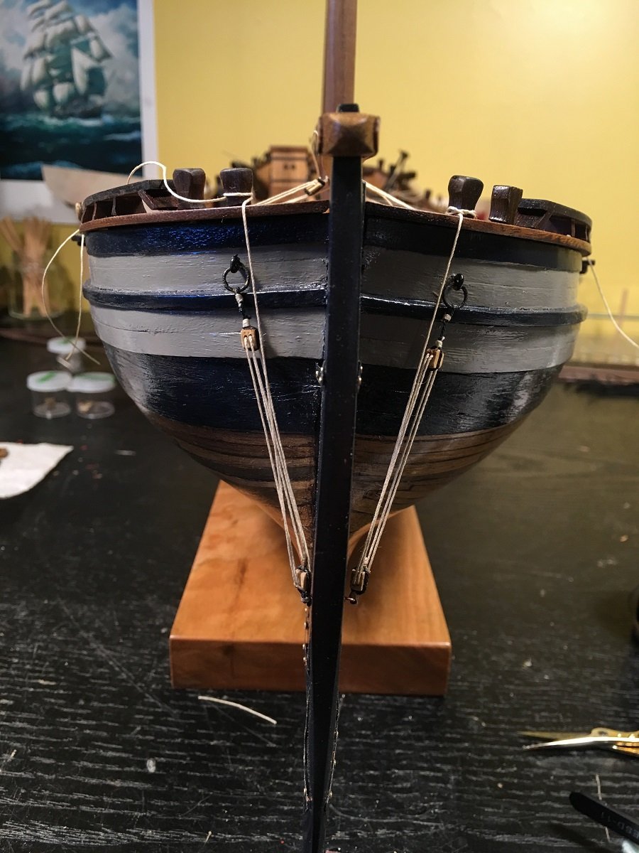
Minor progress. 2nd and 3rd decks built and the upper bulwarks added. Almost ready to do interior finish below gun deck and then exterior hull finishes. Although the plans are pretty good there are some contradictions between plans and the model photos on the box cover. Having to puzzle out what I have to actually do!
Also noted I have one more pair of gunports to cut for the upper deck