Keith Black
-
Posts
6,681 -
Joined
-
Last visited
Content Type
Profiles
Forums
Gallery
Events
Everything posted by Keith Black
-
 Plunge onward, Captain Tom. I'm right behind you with a fresh bag of popcorn.
- 341 replies
-
- 2
-

-
- Sophie
- Vanguard Models
- (and 1 more)
-
Tom, I'm not suggesting anything, I'm merely trying to follow along. The windows you have drawn on the transom, does that represent sash and glass? Does the distance between windows represent counter timber width or finished mullion width? Can you decrease the distance between the windows allowing the transom to be narrower if that's something you're trying to achieve?
- 341 replies
-
- 2
-
-
- Sophie
- Vanguard Models
- (and 1 more)
-
Tom, understood and I see/understand how the piece fits now, thank you. I figured #7 was dead. Is the piece you made wide enough?
- 341 replies
-
- 2
-
-
- Sophie
- Vanguard Models
- (and 1 more)
-
Tom, don't you have to fit the piece you made in post #33 first and that will then dictate the shear? Trying to be of help but doing a dang poor job of it I'm sure.
- 341 replies
-
- 2
-
-
- Sophie
- Vanguard Models
- (and 1 more)
-
Jim, welcome to MSW. I'm enjoying following along on your Flying Fish build.
-
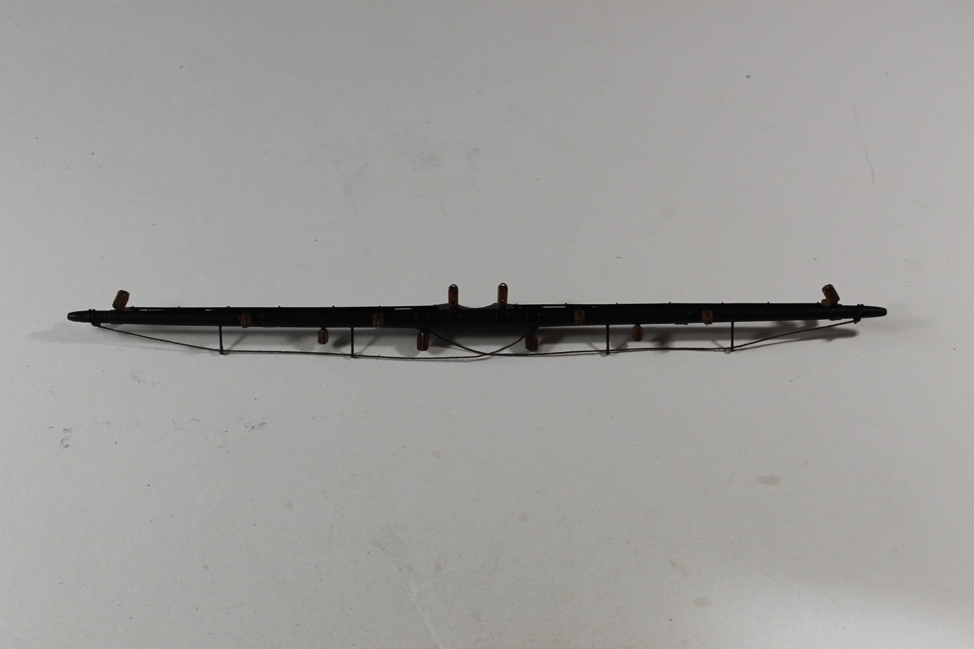
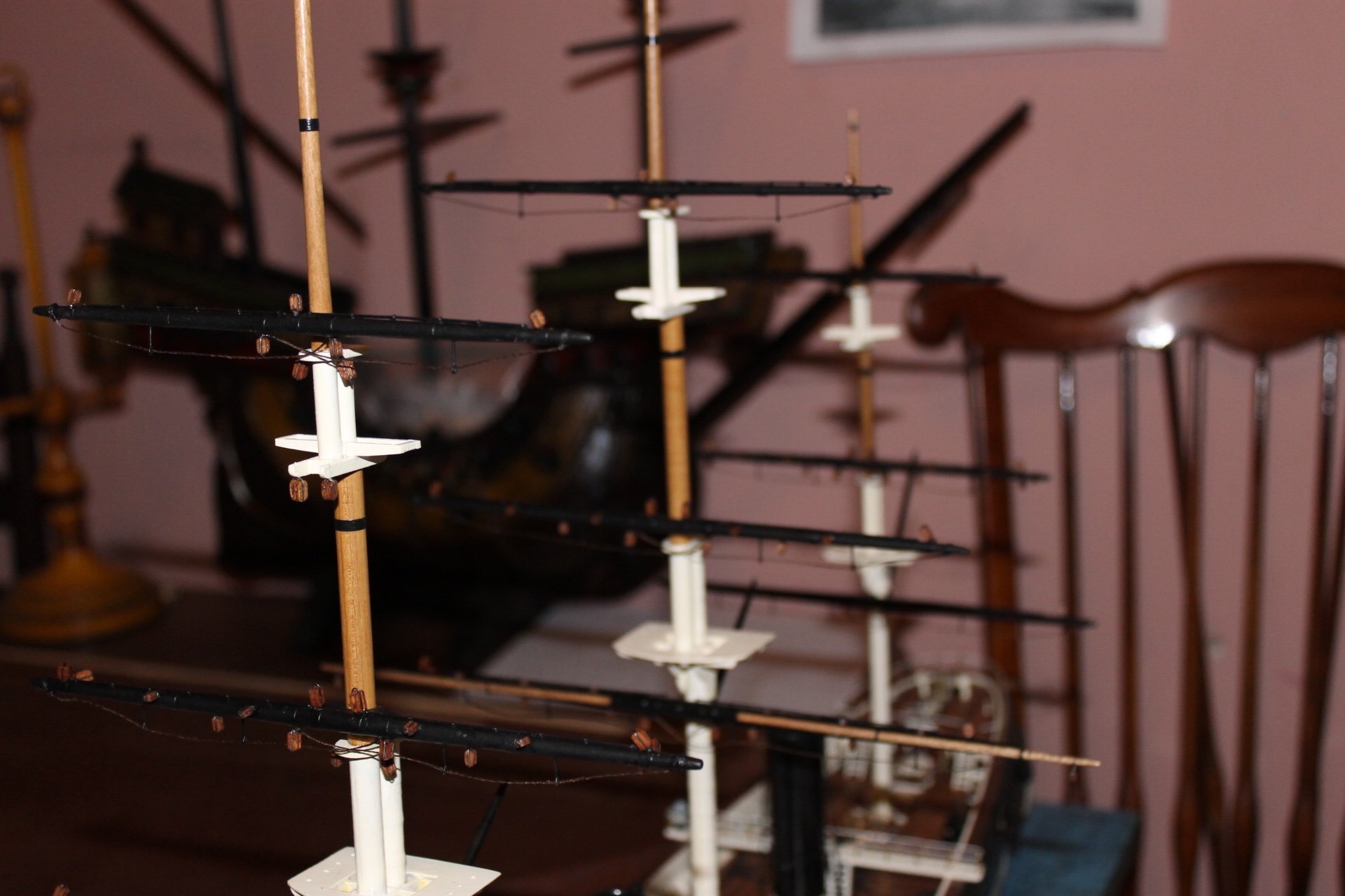
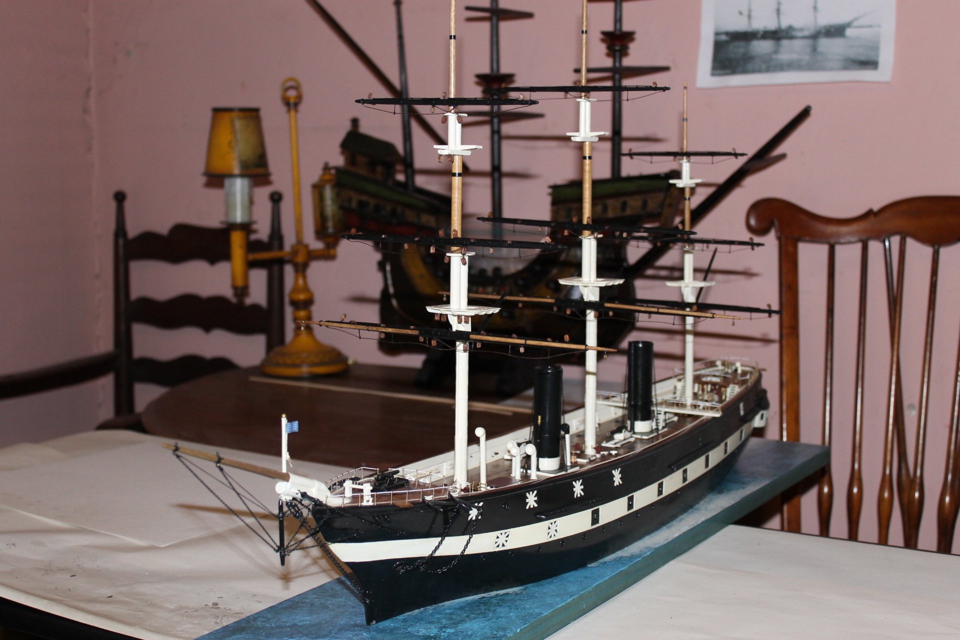
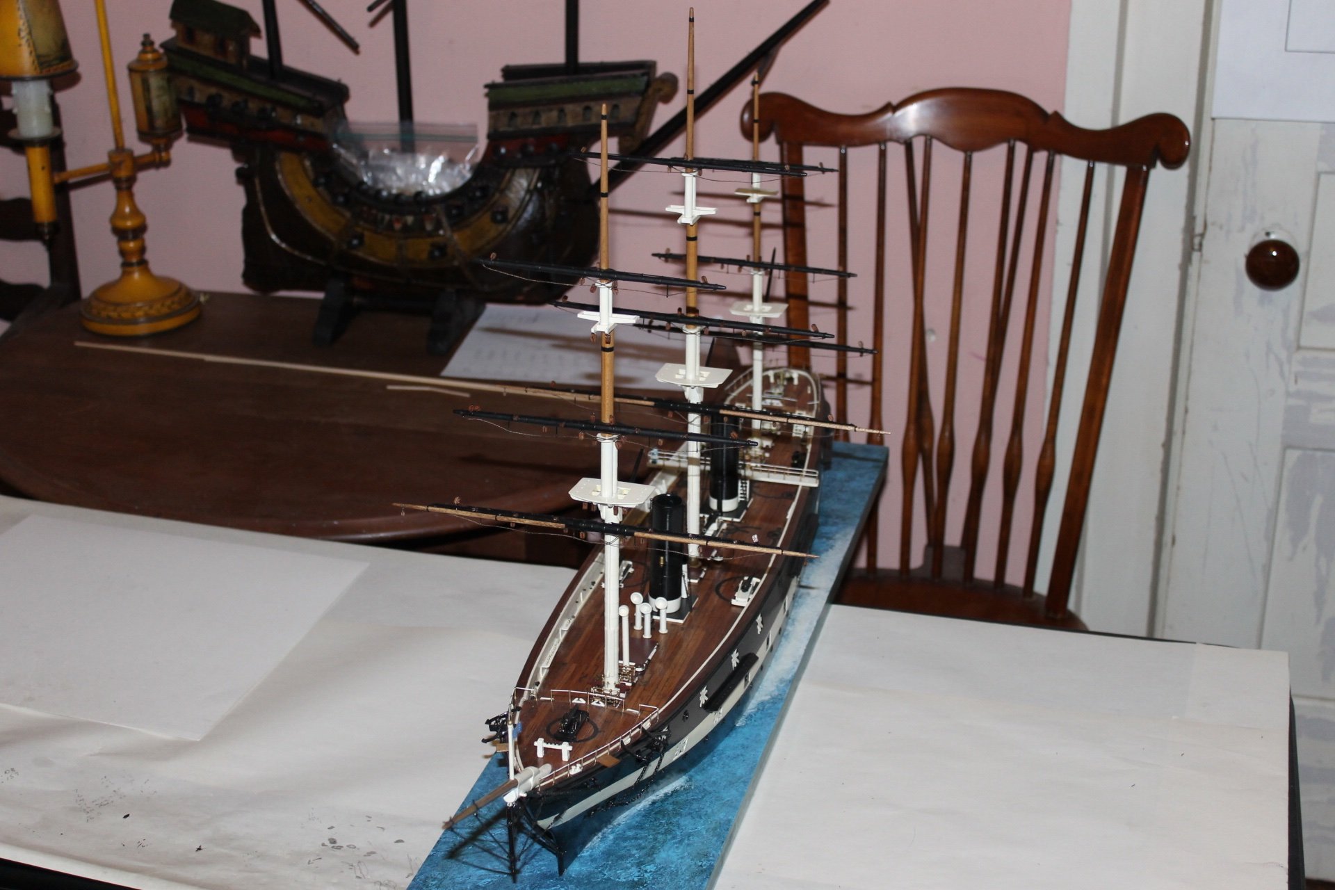
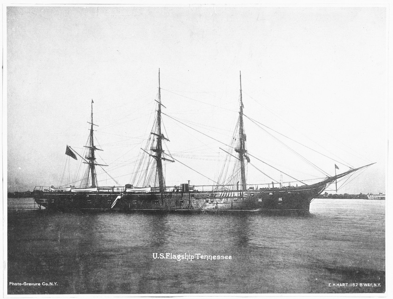
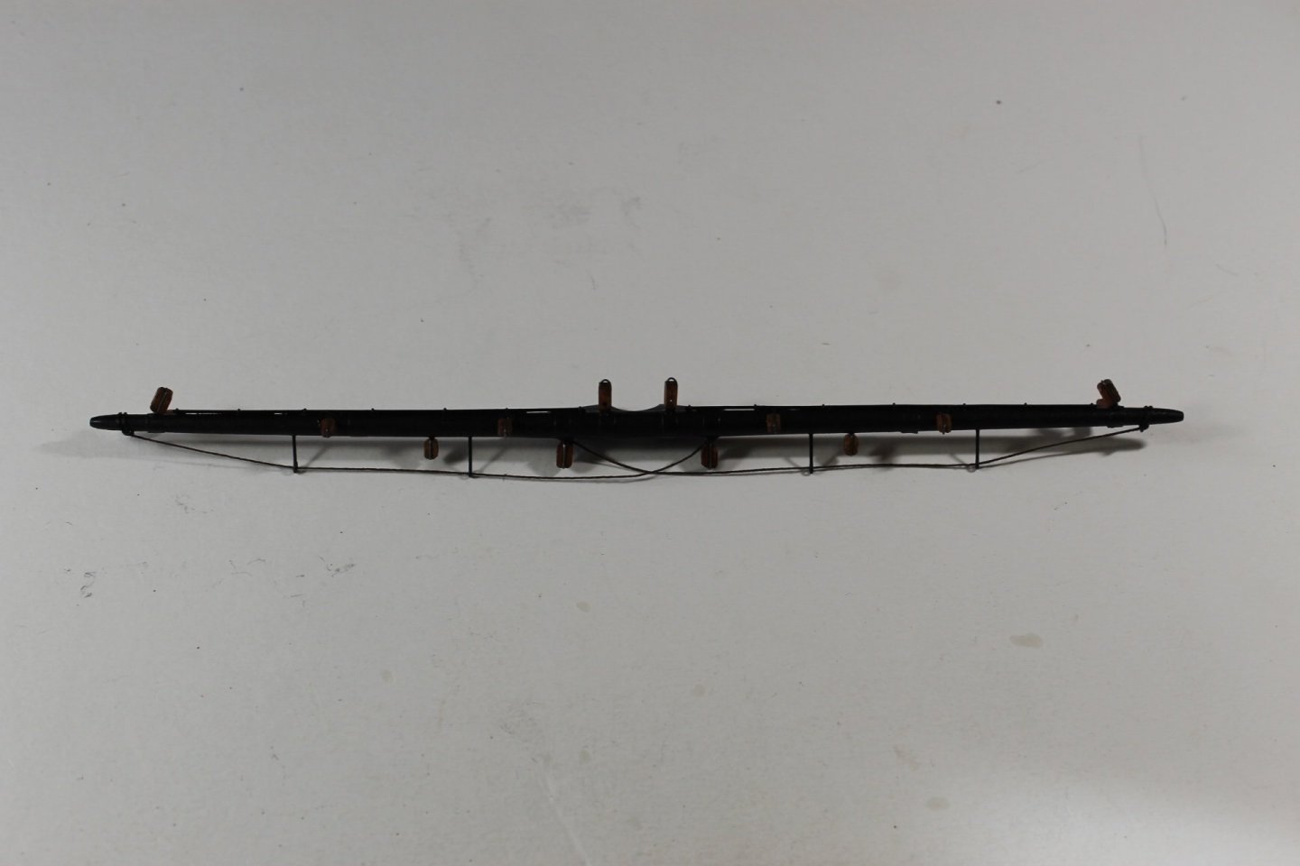
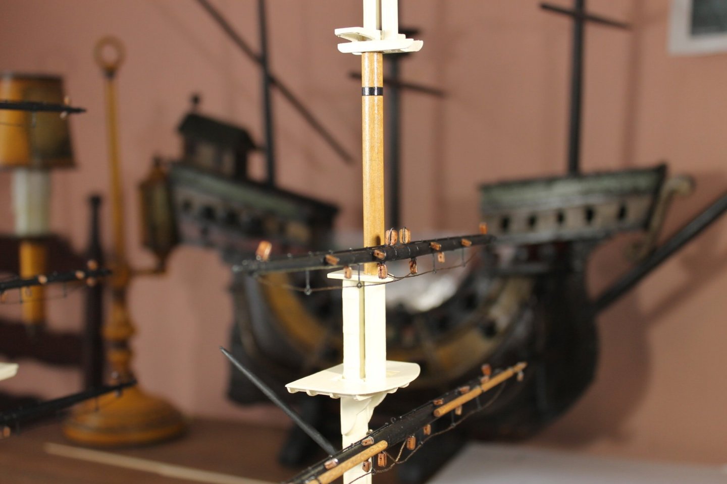
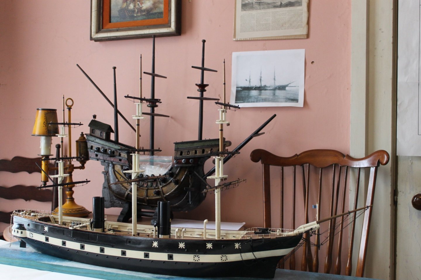
Thank you to all for the likes. Mark, thank you. Thank you, Pat. Glen, first, thank you. Second, I'm posting a couple of pics but I take such lousy photos I doubt you'll be able to see any difference between any of the yards. When I said the last yard (main topsail) turned out the best is more based on feelings than actual visual. Stropping the blocks for the main topsail went without a hitch, there were no issues drilling the holes for the blocks, and the ropewalk came out equal on both sides. One would expect to get better with each successive effort and this was the case with my ninth and final yard. I think it's vital that early on a builder must decide where their model is be placed and how it will be viewed. One side is always better when I make something. With that in mind, when possible, I've placed the best side toward the viewer. Main topsail Main topsail in place. This is the side from which the Tennessee will be displayed.
-
It makes me laugh, it makes me smile, it makes me think back to times when I watched my Dad (who I thought was God) making or repairing whatever at his bench. That same sense of awe sweeps over me, Gary. Thank you.
- 189 replies
-
- 13
-

-
-
Dave, what are you going to do about the missing cannon?
-
Charles, no problem. Would it be possible once a false plug/tampon was glued on the muzzle face to drill and add a eye pin to represent a ring bolt?
-
Roger, thank you. That's what I was trying to suggest in post #9 when I said "What you might try is to make the end of a wooded plug (just a sliver) and glue it to the muzzle" I think Charles misunderstood me?
-
Dave, pin drill and pin vise are the same animal. Sorry, i didn't realize the cannon were brass so I agree with Charles, forget drilling out thee muzzles. What you might try is to make the end of a wooded plug (just a sliver) and glue it to the muzzle? What do you think, Charles?
-
Thank you to all for the comments and likes, I am truly humbled. All the yards are populated with their respective blocks. Of course the last yard I did turned out the best of the nine, isn't that always the case. I still need to seal the yards. So it's on to stropping the blocks for the mast and gaffs. Thank you again for stopping by and providing me your support. Slowly but surely we're getting there.


-
She appears awfully low in the water and heavy seas would see waves sharing the Captain's table?
- 341 replies
-
- 1
-
-
- Sophie
- Vanguard Models
- (and 1 more)
-
Nor did I, Mark, my experience like yours was in AIT. Maybe it was a slow day and the instructors let us play around a bit longer than usual.
- 27 replies
-
- 2
-
-
- eBay
- kit piracy
- (and 1 more)
-
Dave, do you have a pin vice? If not it's one of the most important tools you can own along with a set of good micro drills. I'm working at 1:120 scale and I was able to bore out the ends of the guns I made. You don't need to drill more than a quarter of an inch deep.
-
Dave, as Tom Silva says, "money's in the details" or the old saw "devil is in the details". The more time you spend working on the details, the better model you're going to have in the end. Model ship building is a marathon of patience. It's not how fast you get to the end, it's how well you journeyed to get there. This is your crossroads, it's the point where Dave has to decide if he's going to do the very best he can no matter what or how long it takes, or if he decides to settle for mediocrity. Please believe me when I say I don't mean to sound rude because I'm not trying to be. You see, I'm pulling for Dave to model the best Lady Nelson possible.
-
And then there's the electric drill lathe which you probably already own.
-
Mark, you fired one. If memory serves, you could get off two rounds (provided the arc was high enough) before the first one landed. Is that correct or have I watched too many war movies since our Vietnam getaway?
- 27 replies
-
- 2
-
-
- eBay
- kit piracy
- (and 1 more)
-
The M79 was a fun weapon to shoot. It had an easy kick with a pleasant 'thunk' when fired.
- 27 replies
-
- 4
-
-
- eBay
- kit piracy
- (and 1 more)
-
Dan, welcome to MSW. I look forward to seeing your work in a build log.
-
Keith, elegant solution, it turned out great. Have you thought about making custom hamster wheels?
-
Once again, I've never tiled a hull so I'm talking out my hat more or less. In my mind I see gluing nice shinny new tile onto the hull being much easier than tile that's been messed about with. The more even/flat the edges and no chemical residue left on the tile's glue side sounds like the ticket. Reading what folks have gone through coppering a hull individual tile is a difficult and messy process. Eric, have you thought about using copper tape and a pounce wheel? Attached is a good discussion regarding tape vs tile.
-
I've never tiled a hull so my advise is based solely on observation. The best copper tiled hull I've seen is where the modeler tiled three rows down from the waterline and then tiled the keel and continued to tile up to meet the first three rows laid down. As far a tile weathering, a heavily weathered copper hull looks a bit odd when no other weathering techniques are employed on the rest of the ship. If one is going to model the ship as new then the copper sheathing should only have a light patina IMHO.
-
Eric, IMHO you need to buy another set and start over. I don't think you need to be open flame aggressive in aging the tiles. Putting them on first and then chemical aging them is going to work out best for you.