
Boxbuilds
-
Posts
315 -
Joined
-
Last visited
Content Type
Profiles
Forums
Gallery
Events
Posts posted by Boxbuilds
-
-
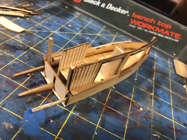
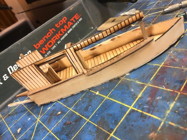
The hull is simple and went together well To provide more freedom in detailing the interior I started framing one side. The side is one large piece and will be supported by vertical supports. I chose to use walnut for the trim and posts. Amidships is a pair of closets that housed gas, water and oil tanks. I am running water and fuel "lines". I made a counter and sink for the galley. The drive shaft runs from the center-mounted 2 cycle engine to the drive support through a space between two wall sections which are now installed. I am fashioning a lavatory from FEMO for the head opposite the galley.

- Keith Black, GrandpaPhil, yvesvidal and 2 others
-
 5
5
-
No, the holes are irregularly formed, unevenly spaced and the nails have split the wood in multiple places. That's the main cause of trim damage......that and rotting wood.
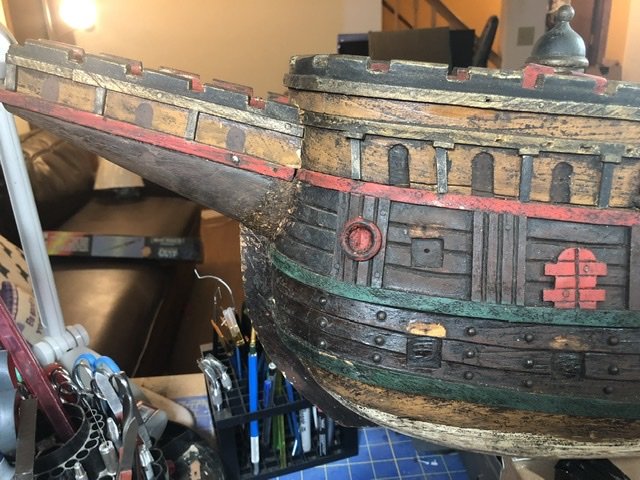
The hull is is almost ready for yards and masts. I installed the guns and repaired damaged trim. Guns that are missing will have to be turned and little spots where paint is missing will be matched and touched up.
- mtaylor, Keith Black, MEDDO and 3 others
-
6
-
I have limited experience with shellac. On a few past woodworking projects shellac has yellowed. I found mast verathane more sustaining. As long as the wood and any underlying paintwork is completely dry, this option has been lasting and strong. Might be worth a try.
- mtaylor, Keith Black, thibaultron and 1 other
-
4
-
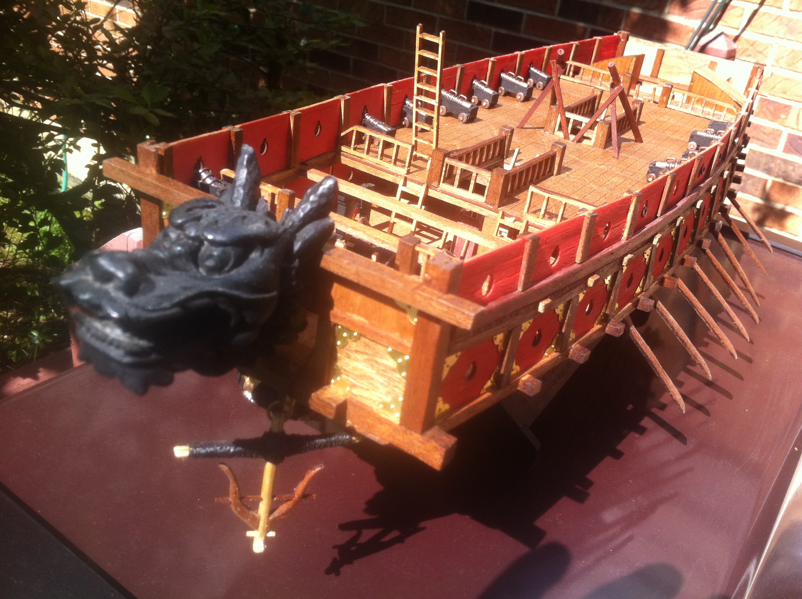
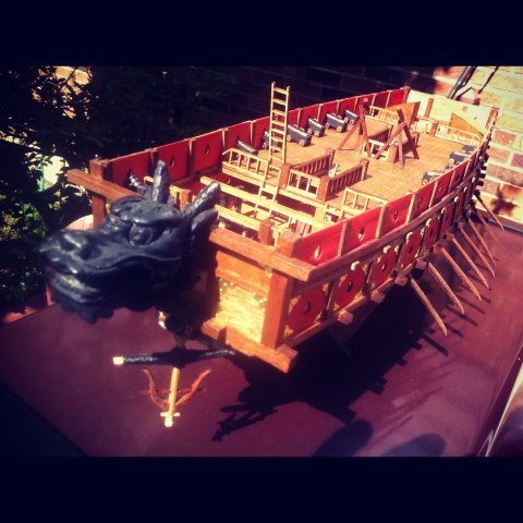
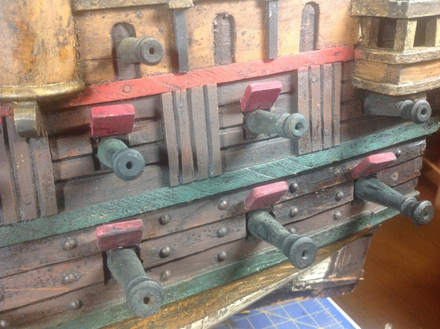
In several places the "trim" has been knocked off. The maker used nails to tack almost all wooden pieces to the hull. The nails, while small were still too big for the small pieces which contributed to a lot of splitting and inevitable loss of some bits. Examining the existing trim, I found in most places that it was 5X2 mm stock painted a mix of black and gold. I used scrap to experiment with the 2 paints in order to achieve the same result. The process I settled on was pretty simple. Black paint was applied as a base and then gold was dry brushed across the black. The gold was much too "new" looking at that point so I dry brushed black across the gold with varying pressure and in uneven patterns. This provided a worn look to the pieces and seems to match the original. Holes in the hull left by original retaining nails and nails used for rigging anchors were drilled. My hope is that predrilling the holes will prevent future splitting when the original nails are re-inserted or replaced.
Gunport covers had been knocked off and lost--about half of them. They had been painted red and nailed to the hull. Also being smallish pieces, several of the remaining covers had serious cracks running along the grain consistent with splitting from the nails. The remaining covers were carefully removed and, where needed, glued to renew their integrity. I measured and cut new stock to size to replace the lost covers. The glue edge was sanded to the right angle and all edges were sanded somewhat round to get the proper age appearance matching the originals. Matching the uneven look of the aged paint involved starting with a dark shade of red and adding layers of watery black paint. By blotting the black before it dried, I achieved a close reproduction. Re-gluing the covers to the hull was simple and replacing the nails completed that task. Again I predrilled the holes.
Touching up the paint where there are scratches and the wood is glaringly uncovered and coating the woodwork with clear satin sealer ends repairs on the hull.
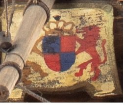
Pictures and paintings of Harry show a design on the transom. Close inspection indicates something, now gone, existed. While the masts are being worked I am going to fashion a replacement.
- Keith Black, gieb8688, mtaylor and 2 others
-
5
-
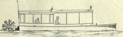
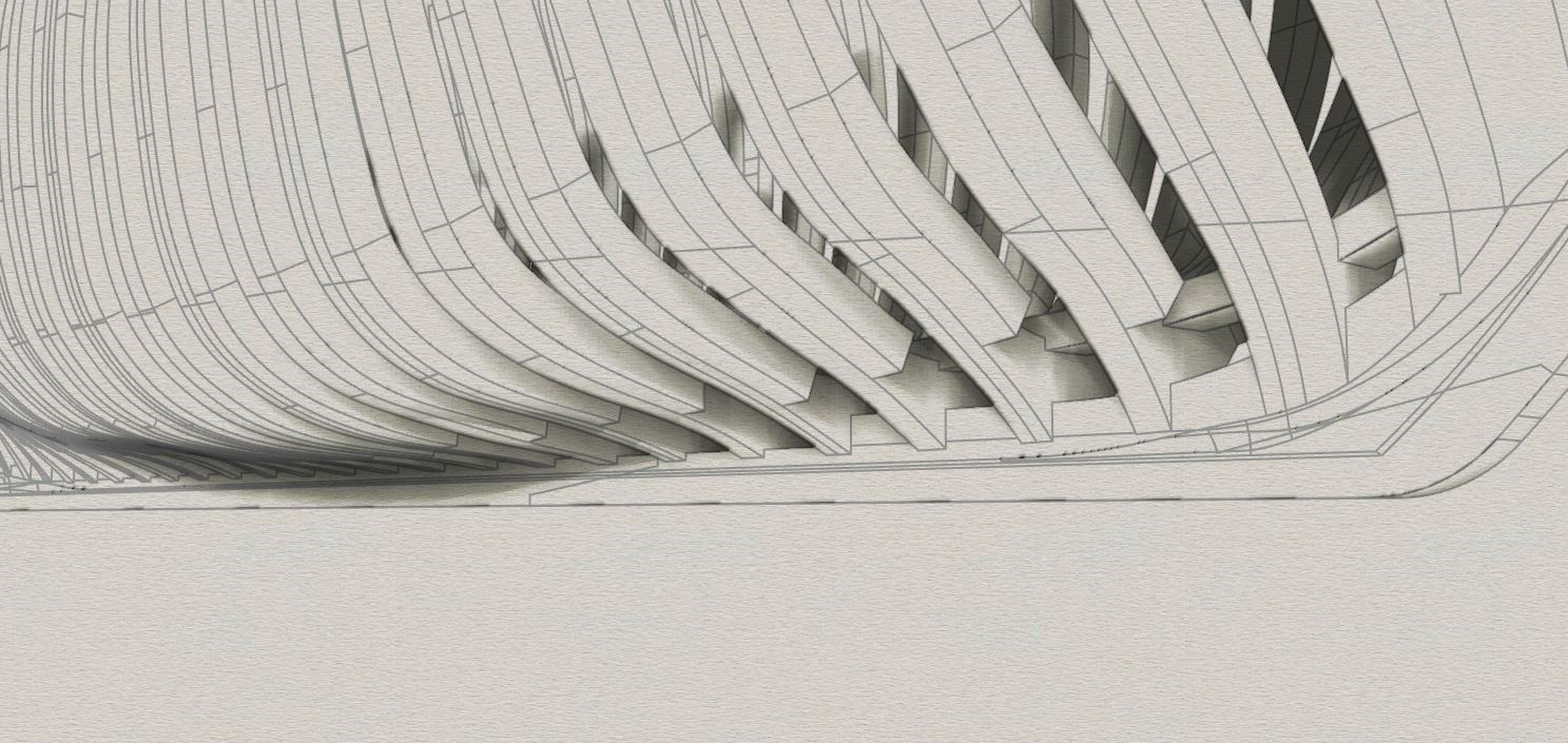
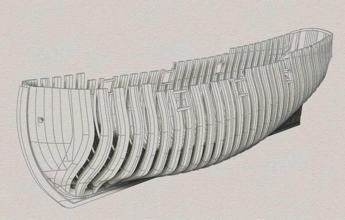
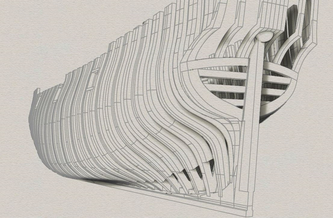
Researching steam powered ships, I came across a plan by Davis that was, to me, unique. I found it in a 1913 book, Nine Motorboats And How To Build Them, published by the Motor Boat Publishing Co. No author, but Davis's plan is listed in contents as a "Light-draft Stern-wheel Boat".
The boat is a 2 cycle gasoline-powered, wooden launch that looks like a pleasure boat or simple water taxi. The hull is perpendicular to the flat bottom with wooden posts for support. It has a false keel, more like a rubbing strake down the middle of the bottom. The superstructure is planked only to house a galley and head. Propulsion is via two 3 foot diameter paddle wheels at the stern. The engine amidships simply transmits power across a drive shaft to a worm drive that spins the paddle axles.

.
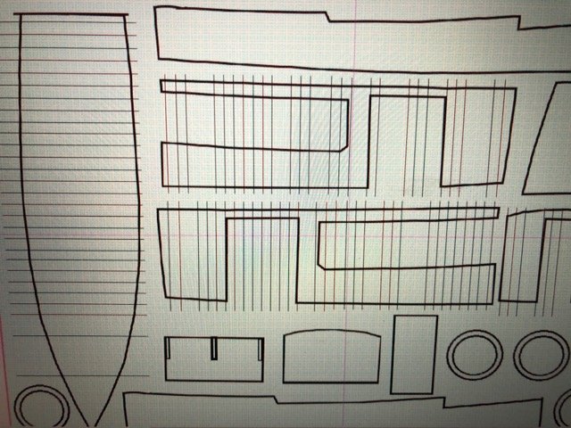
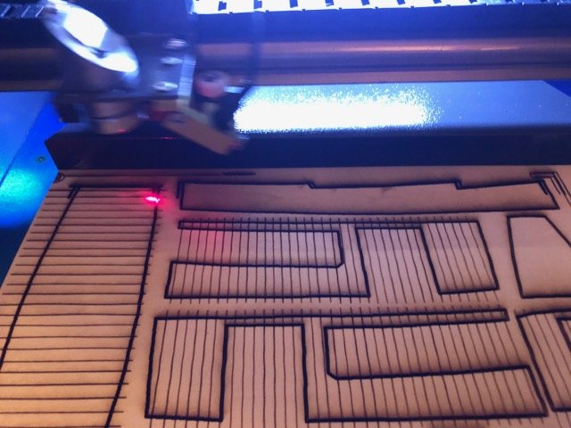
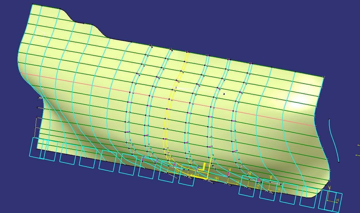
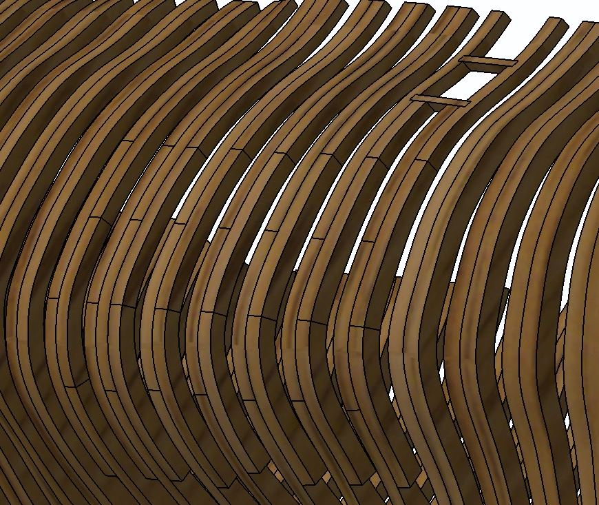
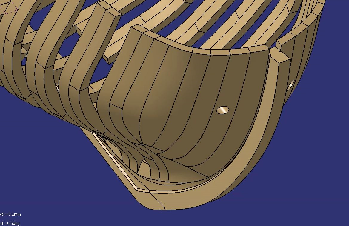
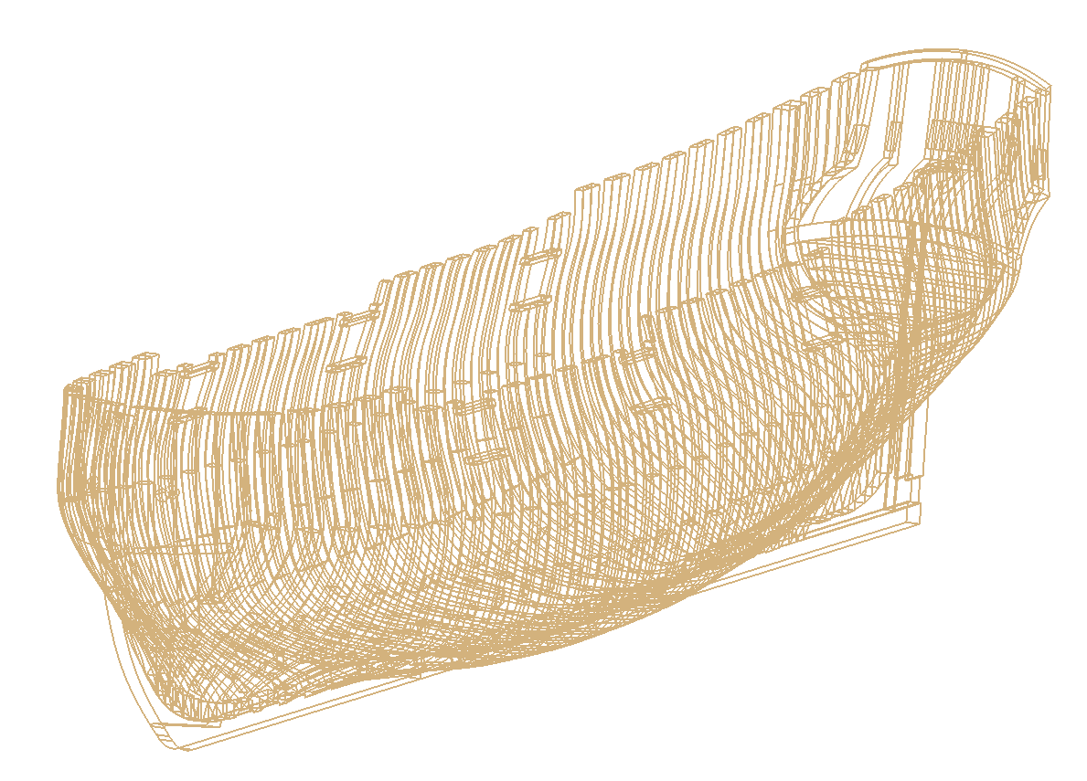
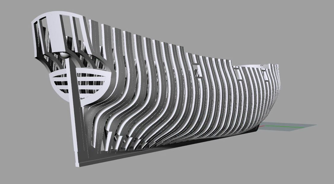
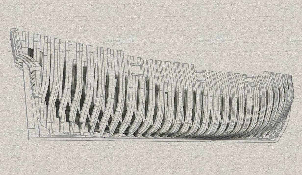
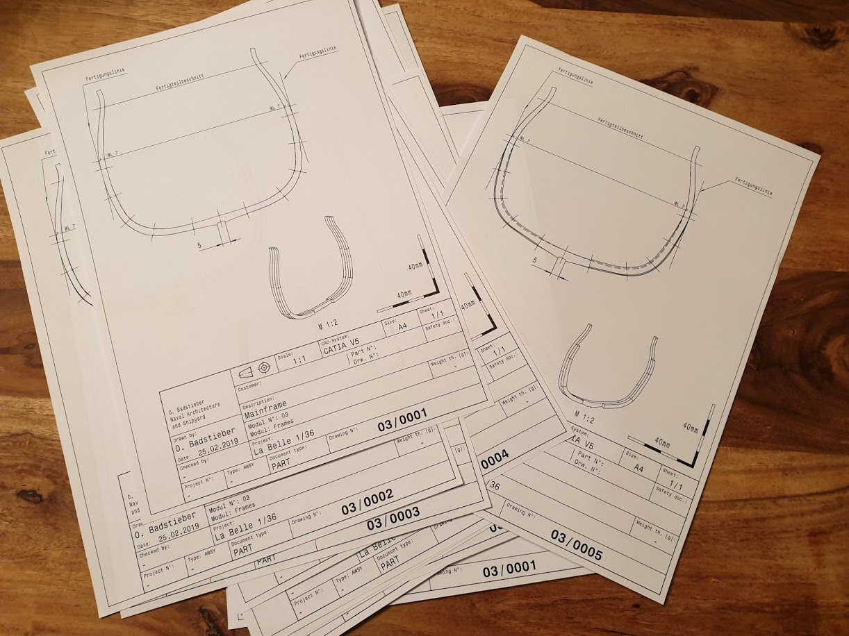
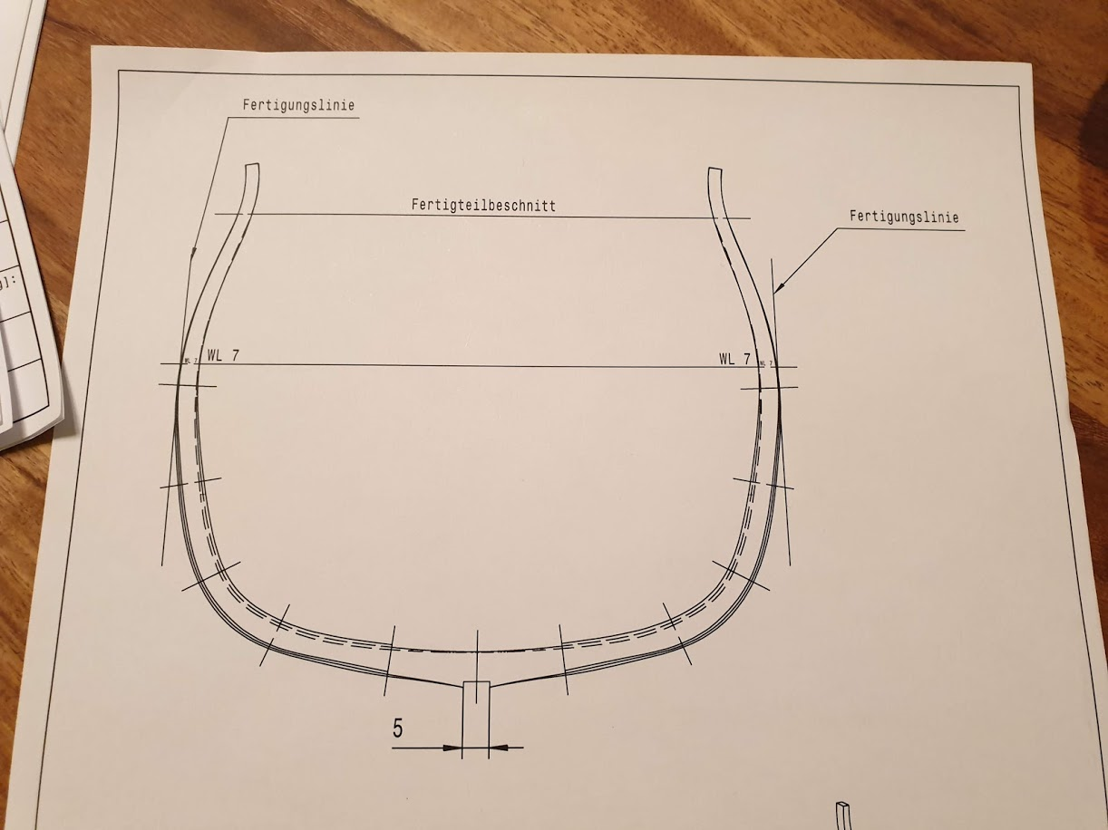
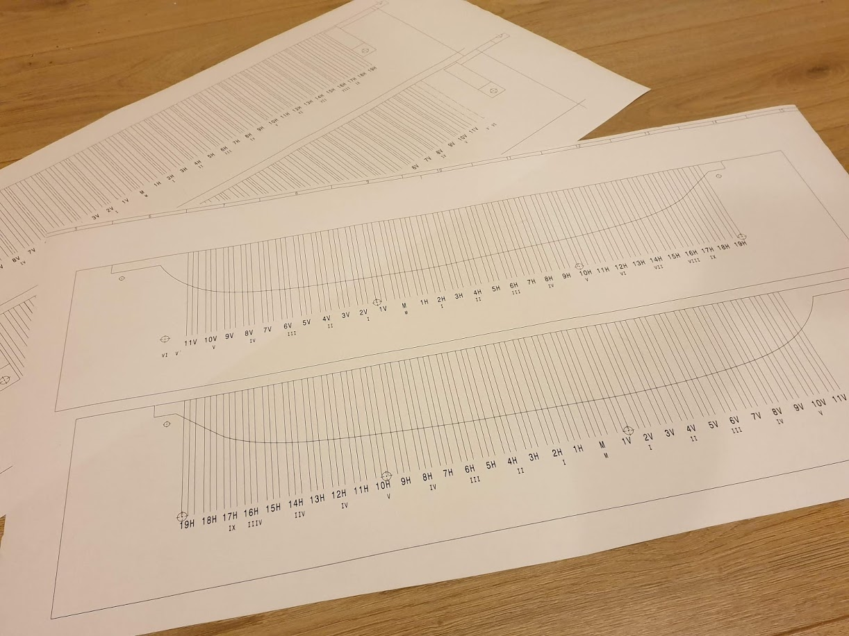
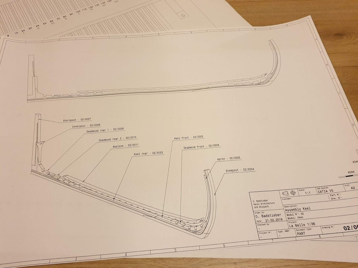
I just got a laser cutter and decided to make the parts with it. It has been a real learning curve but the parts are coming in.....after 3 or more tries. The first challenge is to identify construction entities that will form the ship. Then it's got to get into an engineering tool(s) to scale and size the items. Engraving versus cutting drawings are created and they are transferred to to laser controller for work. Here's a sample of the drawings and resulting parts. Needless to say I am bumbling my way through this but I see promise in it.
- GrandpaPhil, Keith Black, KeithAug and 3 others
-
6
-
-
Michael,
You are creating a masterful rendition of the SR and demonstrate a fine insight into improving on the plans.
I wish I had seen this thread BEFORE following the instructions on my SS. I have a Sergal model earlier than yours, I believe. While I keep busy with other builds, it's partially because I am not happy with where I am with SS results so far. The short story is that I planked the hull and found out the 1:1 plan that came with the model doesn't line up with where the gun supports are...it is hit and miss. You can see the faint pencil marks at the "plan" positions. At this point I am going to either rip the planking off and replicate your approach or place dummy blocks where the current ports are to hold the guns. Furthermore it has been frustrating to work on doorways and gunport frames now that the ship is planked and decks are installed. I already had to take the uppermost deck off to do work. This has been two steps forward and one back for years.
I won't ask how you knew to create this sequence of build, because it is different from my set of instructions, but is there a guide I can use that leads along the same path you're following?....aside from this thread.
-
Thanks fellas. Once the beak is smoothed the hull will only need minor work like gunport covers or broken pieces of wood fixed. The sails are cleaned but I have to make one to replace the bonaventure missen sail that is missing. That'll be an adventure in experimentation. Darrell is working on the next major step, assembling and rigging the masts based on Bill's rigging plan. When that work is rejoined with the hull "Harry" will be well on his way to Greatness again.
Attached is Bill Nyberg's description of the running rigging based upon the "Great Harry" in the Powerhouse Museum, Sidney. It is an excellent evaluation of the port and starboard views. He prefaces it:
"I wrestle with how to document how the model had been rigged, originally thinking I could do as I did with the standing rigging. That got extremely confusing to me very quickly.
The document is arranged from bowsprit back to the Bonaventure mast. I would suggest that the yards be rigged and sail attached and how the yards will be attached and held in place on the masts be completed before the running rigging is started. Also, if you have reviewed the photos, the way the running rigging terminates is very confusing and in many cases not clearly understood from the photo. "
Note: Few of the original lines were terminated at the deck. Most terminate on the masts below a top, I guess for manufacturing convenience. This was a challenge, being so unconventional, and a tribute to Bill's patience.
- mtaylor, Louie da fly and Keith Black
-
3
-
Thanks for the vote of support Mike. There's always another decision to make with these projects. I need to hold onto some kind of approach/theme to help with the choices but that doesn't mean I'm right. Friends' input helps.
- mtaylor, Louie da fly, MEDDO and 1 other
-
4
-
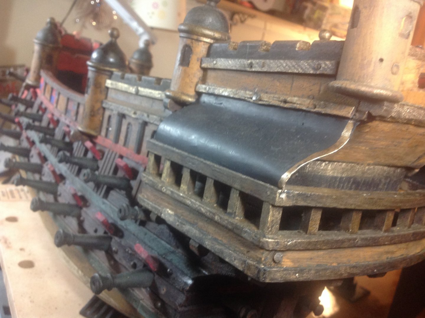
One of the integrity issues with the hull was a loose prow/ beak. It appears that it had been nailed but the old wood was no longer holding. I installed two wooden dowels between the prow and hull. They are invisible but holding firmly. Aligning the matching holes for the dowels on an uneven surface was tricky. Once set and glued there was still a seam that was too rough. I mixed up glue with sawdust from the model to fill the crack. You can see the fill that needs to dry and be sanded down tomorrow.
The model had lost its columns that graced the hull flanking the brown arched portals. The first 2 are painted, guilted and aged. The 2 to the right are installed awaiting finishing.
Age is attacking the solid hull in the form of cracks. While I had considered filling them all I think it would detract from the model’s “mature” look. I’ll lay on a coat of satin sealer as a preservative to mitigate the aging
-
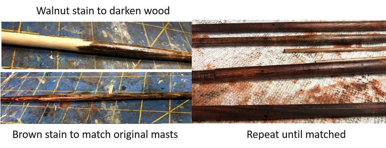
Finally finished the stepped masts. Since the MAAS model has stepped main and fore masts the owner said she wanted the solid masts cut. I used all the pieces of original mast possible. A few new pieces had to be fashioned though. The big challenge in that is matching new wood to wood almost a century old. Using basswood the pieces were shaped and multiple applications of stain were applied to establish the match.
The original model had not mast caps. The MAAS model does so I made them for the sections of the main and fore masts. The top of the mast sections were squared off and the caps were carved and cut proportionately. Flag masts at the top of all 4 masts also required caps and, in fact, making the flag masts. The flags are present but were not mounted. In all the main mast now exceeds 48".
-
Keith,
I used copious amounts of Goof Off superglue remover. After removing excess glue around the mast to give it a little wiggle room. The mast was nailed at the bottom so it took awhile but eventually it rocked loose. I think the key is dissolving the glue.
- mtaylor and Keith Black
-
2
-
It's impressive to see the precision of the thin window frames
-
How did you maintain symmetry between the two sides of such a complex figurehead?
- mtaylor and FrankWouts
-
2
-
I have one of these in my stash of models and you've inspired me to move it up in my build list. Not sure I could come close to your carving skill though
- FrankWouts and mtaylor
-
2
-
I've used scrap tile with a smooth surface
-
On 10/23/2016 at 4:44 PM, Landrotten Highlander said:
might work if you use a plastic brush. The steel or copper brushes would imho be prone to create undesirable lines.
Don't forget the cloth polishing brushes. I've found that a CLEAN brush lightly applied at medium speed smoothies rough spots sometimes.
-
I'd like such steady hands and sharp eyes. I'm sure we can learn a thing or two from you.
-
Nice matching effort on the lantern. Looks original.
- mtaylor and Keith Black
-
2
-
-
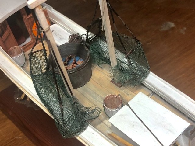
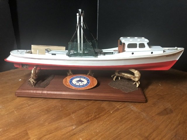
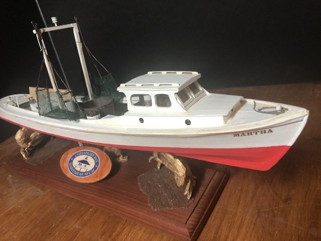
To make Martha “work” I reviewed pics of other small crab boats on the Chesapeake to identify some of the equipment used. In short, I added crab scrapes, blue crabs, crab tub, buckets, net, life vest, gas can, toolbox, fire extinguisher, cooler, nav light, floatation cushions, floor grate, gauges, sorting board and ropes.
To give miss Martha a slightly lived in look I put in a false deck that was weathered. I added thick layers of paint representing many years of maintenance. Woodwork was slightly worn with sandpaper after staining. Scuffs and dirt were applied with diluted mud colored paint. Watery black was helpful where oily grime was appropriate.
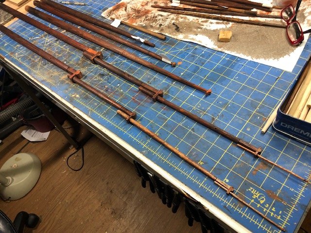
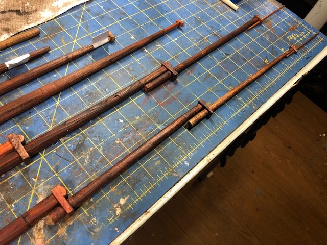
The crab scrapes were made with soft wire and netting. I think the wood frame is instrumental in deploying and retrieving the scrapes.
I used my 3D printer to make 2 crabs as a mount for the stand. I generally use creatures and figures (golden) to hold my models. To hold the identity tag, since my last name is Boeck as in Bock beer, I use golden goats on all my jobs.....kind of a signature. I tagged Martha with the CBMM logo to credit them with this great kit.
Now, on to the next
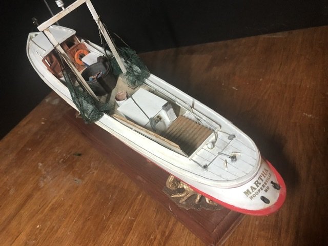
The steering mechanism on these boats is unique. Controls are in the aft, near the engine compartment, not in the cabin. Looking at the boat's stern a long vertical lever, blocks, ropes and a steering arm are visible. I drew a little diagram to help illustrate the mechanism. A line is tied to the vertical, steering lever. The line travels from the steering lever through one block and ties to the rudder steering arm. From there the line is passed through the other block, through feeds along the boat bulwark into the cabin, around the perimeter of the cabin and back out the other side of the cabin. Finally the line continues through the feeds and terminating at the vertical steering lever. By moving the lever to the back of the boat the lines pull the rudder to the left and vice versa. With the throttles attached to the engine housing and the adjacent steering lever, the boatman can control his craft.

- Keith Black, VTHokiEE, yvesvidal and 4 others
-
7
-
I cry with wonder....I wish I could do this. your career and patience are producing an exemplary model...no, piece of art. Not diminishing similar experts, you deserve credit for both the quality of your woodwork and the "tutorial" that is being written in your log. Many of us will benefit. Danke.
- mtaylor and Oliver1973
-
2
-
-
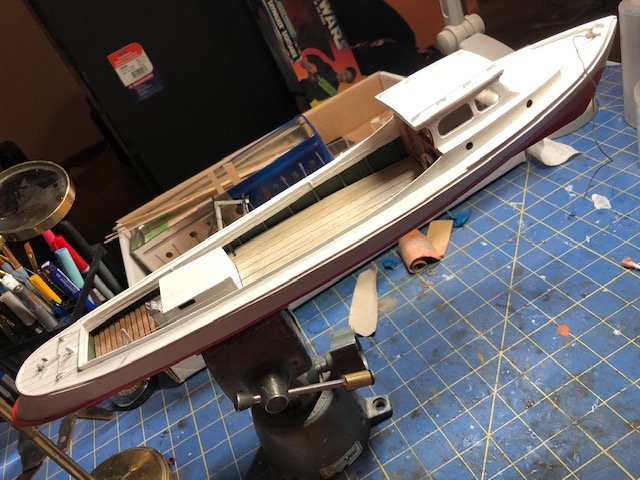
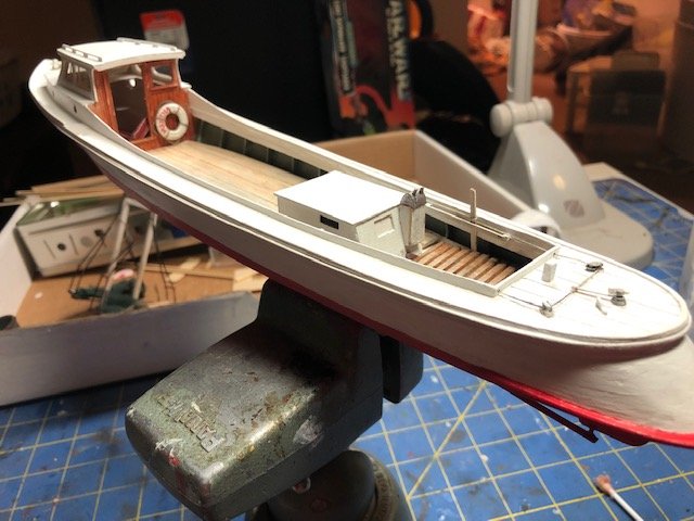
Martha is essentially built. It still needs its decals and touching up. The build had some interesting challenges but was pretty straightforward.
The laser cut parts fit well. Its important to pre-fit and sand a bit. The cabin takes care because there is a tight dependency to getting all the pieces in line. The steering mechanism is a combination of line, pullies, and a steering lever. The pullies are soft metal. The small holes the lines run through should be cleaned up and enlarged a bit. There are fairleads for the lines which tie off on the steering controls and the rudder lever and run along one side, up to the cabin and back in one large loop. The fairleads were wooden, small and really fragile. I managed to break one and decided to use half of a split ring instead. Once the cabin is built it is unlikely the line could be properly run, so do it before.
I have decided to modify the boat and make it "Martha" at work....at least my impression of a day on the bay.
- thibaultron, Keith Black, MEDDO and 4 others
-
7


La Niña by CRI-CRI - FINISHED - scale 1/48 - ship of Cristoforo Colombo - 1492
in - Subjects built Up to and including 1500 AD
Posted
Your painstaking work will be directly transferable to the Sao Maria. I will use your technique with the long boat mold.