HOLIDAY DONATION DRIVE - SUPPORT MSW - DO YOUR PART TO KEEP THIS GREAT FORUM GOING! (Only 20 donations so far - C'mon guys!)
×


shipmodel
-
Posts
941 -
Joined
-
Last visited
Content Type
Profiles
Forums
Gallery
Events
Everything posted by shipmodel
-
 I wasn't aware of the Scientific American article, but I doubt that the torpedo boat made the trip to Cuba. It is clear from the photo of the Maine entering Havana harbor that it was not aboard at the time. Nor was it on the ship in later photos while moored. Conspiracy and cover-up speculation aside, I don't remember it being mentioned at any point in any of the testimony during the several inquests following the explosion. I opted not to mount either one in the display for the Brooklyn Navy Yard museum. As they used to say - "Yer pays yer money and yer takes yer choice." Best of success. Dan
 -
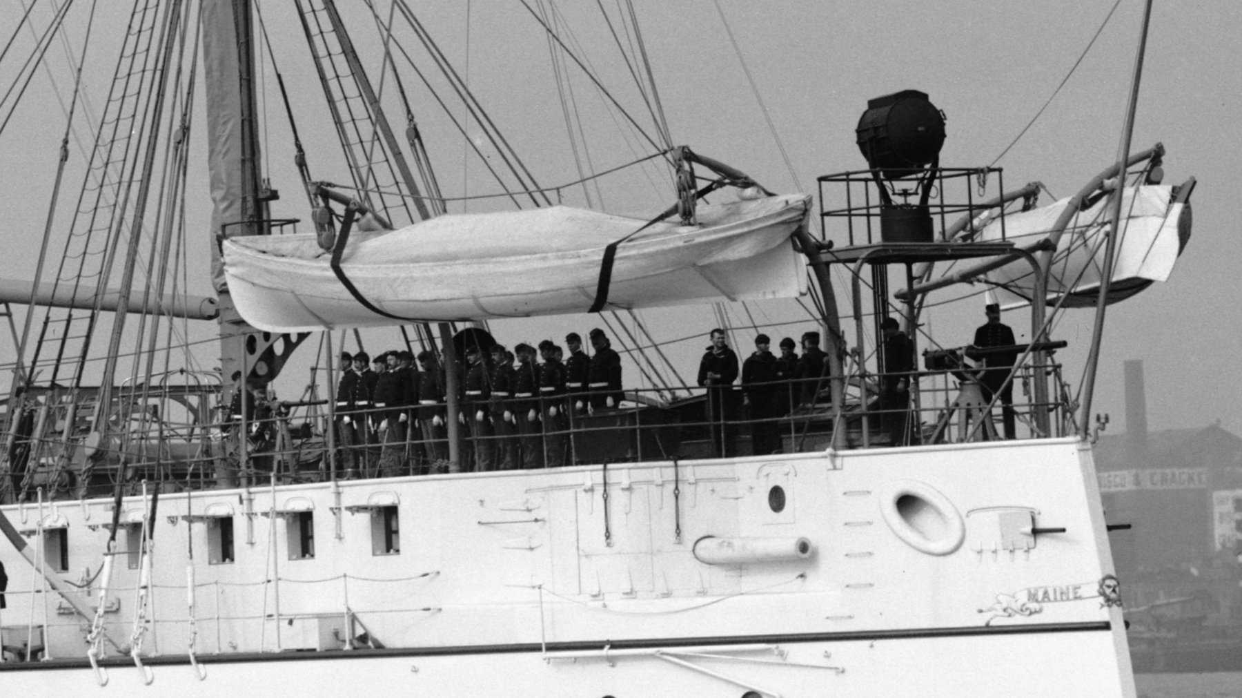
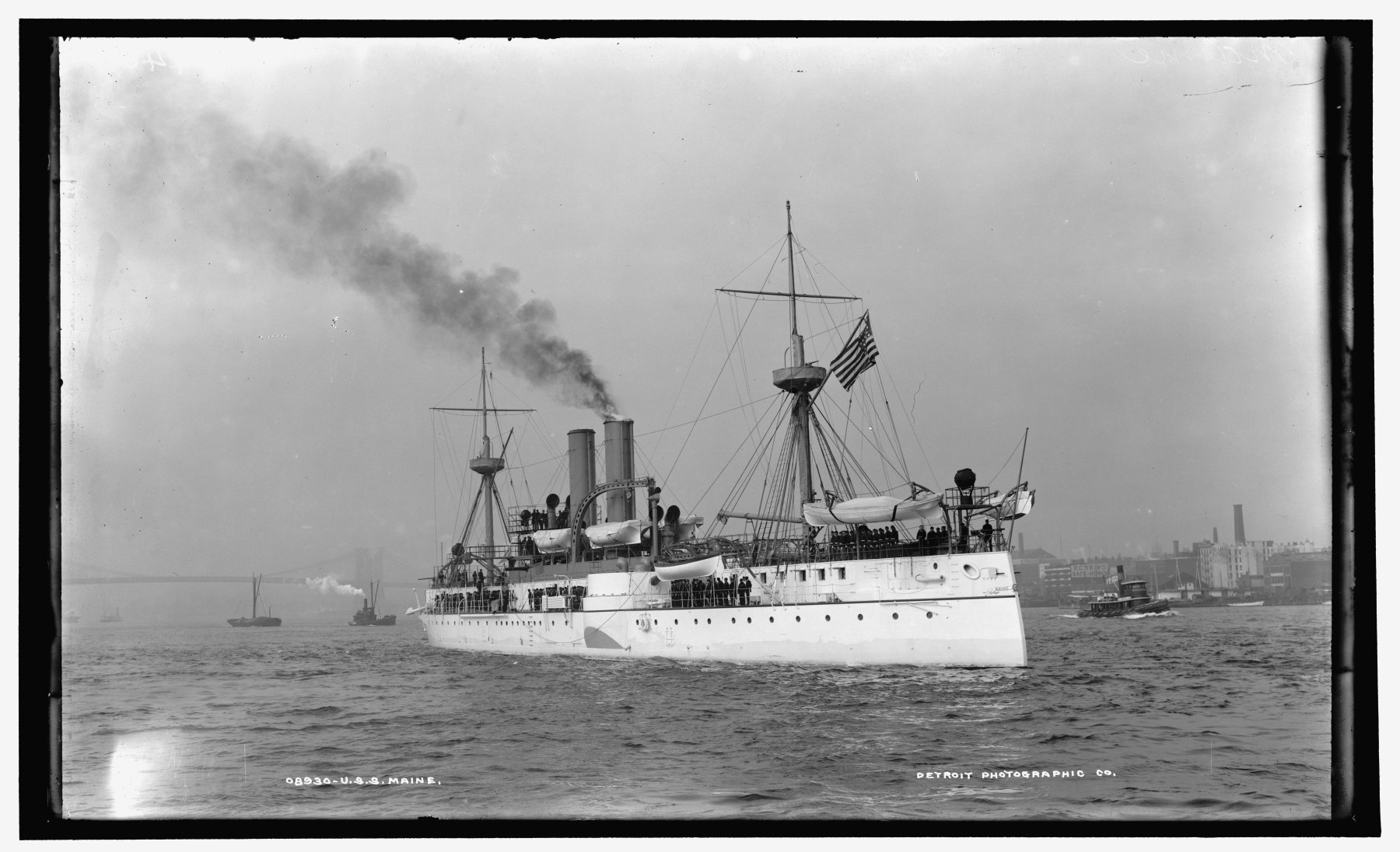
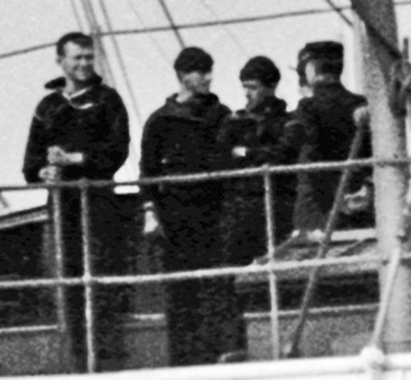
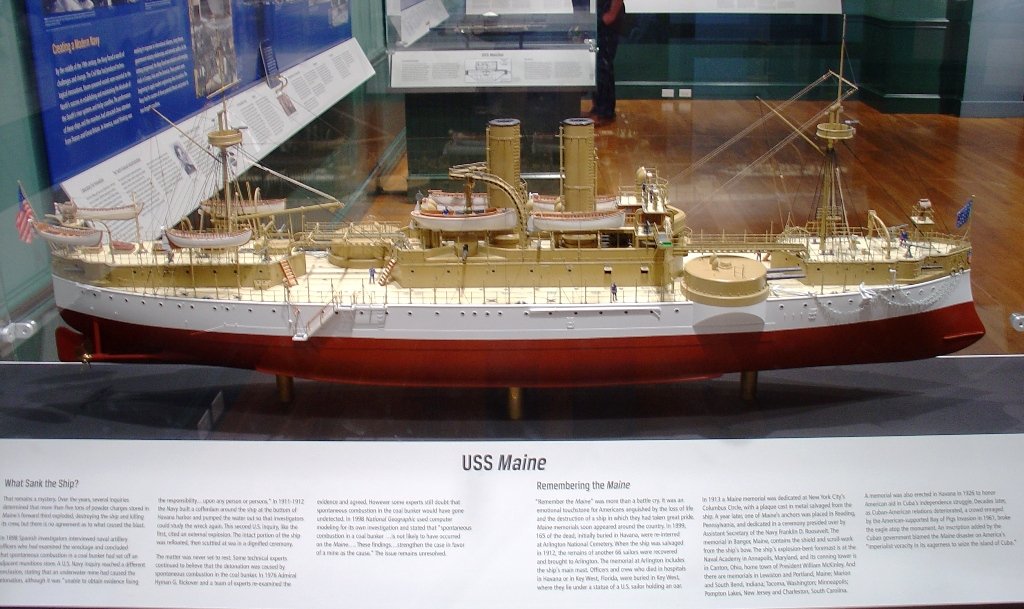
Hi there - Another very interesting build using modern technology. I will be following with lots of interest. I did a USS Maine in the same scale some time ago and found out two things that might be useful to you. First, although authorized, the torpedo boats were never carried by the Maine in the two years between her commissioning in 1896 and her end in 1898. I had to scrap the ones that I started. You can certainly add them to your model, and they look good, but not historically accurate. Also, there were a series of photographs taken of the entire ship from various angles and others taken on deck in several places. These are in the Library of Congress and have been scanned at 1200 bpi, so they can be enlarged to an amazing degree, which can show many construction details that do not show up anywhere else. They are free to download from the Library's website, which I don't have at the moment. Let me know and I can dig it up for you. In the meanwhile, below is what can be done with an enlargement of one of the overall shots. Hope it is useful to you. Dan


-
Hi Charlie - The shipbuilders' rule is that no plank should ever taper to less than half its original width. When you find your spiled planks getting that narrow, it's time for a drop plank. Now that you have some planks laid, you can pencil in the rest of the strakes to see where stealers will be needed. Looking good. Dan
- 362 replies
-
- 4
-

-
- active
- revenue cutter
- (and 1 more)
-
Hi Charlie - The planking is coming along nicely. Your technique with the thinned putty is a good one and should work well for you. Something that works for me when spiling is to first lay on a piece of frosted tape over the curved area to be planked, then draw the plank shape on it. Take it off and lay it flat onto cardstock. Cut it out to make your pattern. When you are confident, you can lay the tape directly onto your planks and skip the cardstock step entirely. Dan
- 362 replies
-
- 5
-
-
- active
- revenue cutter
- (and 1 more)
-
Nils - A beautiful rendition of an unusual subject. Bravo. Dan
- 692 replies
-
- 5
-
-
- eagle of algier
- chebec
- (and 2 more)
-
Swan class 3D model in progress
shipmodel replied to dvm27's topic in CAD and 3D Modelling/Drafting Plans with Software
Brilliant, Denis! I will be smiling all day. Dan- 141 replies
-
- 6
-
-
- pof swan series
- swan
- (and 1 more)
-
Very nice work, Marc - The port decorations came out even better than I thought they would. With a coat of primer many of those differences will be minimized, and I am sure that an integral whole appearance will arise from the disparate colors and textures that you have now. Looking forward to seeing her grow. Dan
- 2,696 replies
-
- 3
-
-
- heller
- soleil royal
- (and 9 more)
-
Thank you all. It was a very enjoyable project, and I am happy if it contributes, in a small way, to the general appreciation of maritime history. The North Carolina people have done a great job with their museum and especially curator Paul Fontenoy and historian David Moore whose excellent article on the ship appears in the latest issue of the Nautical Research Journal. Be well Dan
- 241 replies
-
- 2
-
-
- queen annes revenge
- pirate
- (and 2 more)
-
Hi Aviaamator - Thanks for looking in and enjoying my journey. I hope the machines and devices can make your own modeling a bit easier. One small note - almost all of the rigging, with the exception of the smallest seizing line, is museum grade linen line from a supply that I have been carefully hoarding for years. Only the color has been changed from natural to black for the standing rigging with fabric dye. Be well Dan
- 241 replies
-
- 2
-
-
- queen annes revenge
- pirate
- (and 2 more)
-
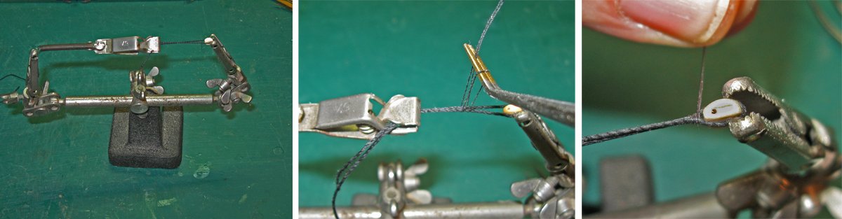
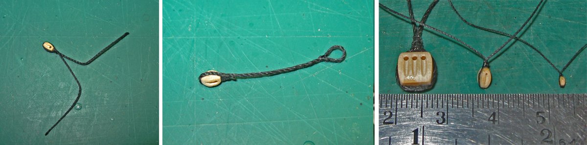
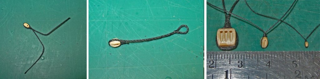
Hi Mark - Yes, working with very small blocks is tedious, but I have developed some techniques that have simplified the process for me. Here is a quick overview of the one that I use the most. I hope that it can give you some ideas for your own work: The central concept is that the stropping line is always under tension until the stropping is complete. To do this, I took a Helping Hands tool and added a small alligator clip and a light spring to one of the tool's end clips, the left one in my case because I am right handed. The selected stropping line is wrapped around three sides of the block and clipped into the stationary jaws on the right, with the tails held firmly in the spring clip (a). The selected serving line (always smaller than the stropping line) is looped or tied around the strop tails (b), then wound tightly up towards the block, forming a nicely tapered siezing (c). This is glued with your favorite glue and left to dry. Once the glue is dry the extra seizing line is snipped off and the block is released. At this point it has two tails, making it suitable for tying the block to a spar or other rigging point (a). If the block is going to be at the end of a pendant or other similar location, one of the tails is cut off very close to the seizing and a loop is seized into the end of the tail in a similar manner (b). This technique works for me from the largest down to really small blocks. In photo (c) the block on the left is a 7mm triple; the middle is a 4mm single which is the one in the photos, and on the right is a 2mm single. The technique is the same, just the choice of stropping and seizing line changes. The smallest block is seized with fly tying thread, which is about the smallest that my old hands and eyes can still work with. On that note, an added benefit is that with the tails on it is much harder for the block to get itself lost when I am opening up the sheave holes. Of course there is more - seizing in hooks or eyebolts to the blocks, double stropping, etc. but you get the idea, I am sure. You can probably think of some improvements. Hope that helps a bit. Dan

-
Thanks, Keith. But why no comment on our bathing beauty? I put her in just for youngsters like you - Dan
- 287 replies
-
- 4
-
-
- michelangelo
- ocean liner
- (and 1 more)
-
Great work. Congratulations! I learned quite a lot from following your build. Thank you. Dan
-
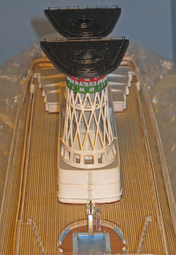
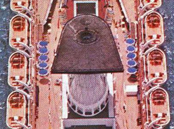
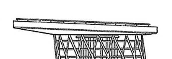
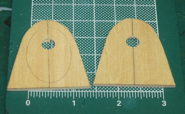
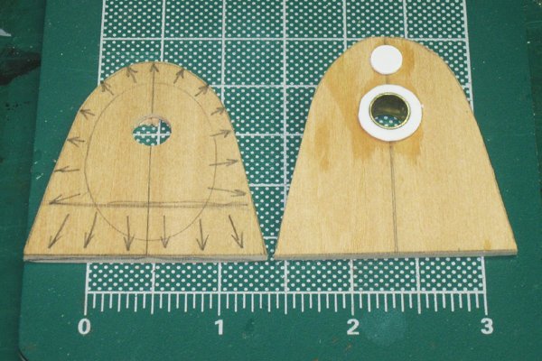
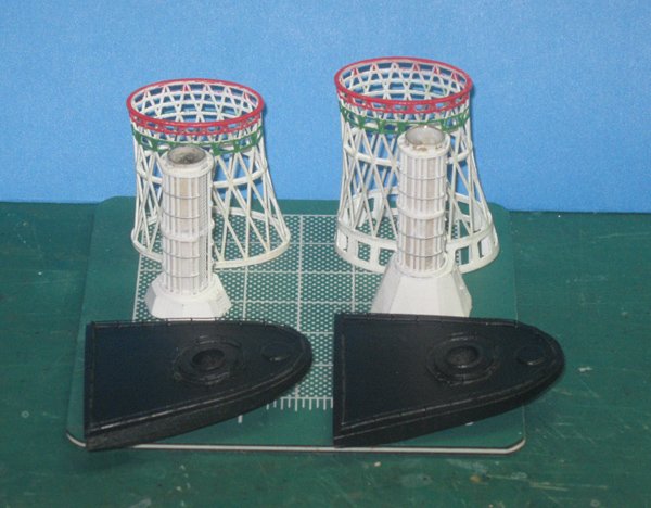
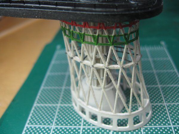
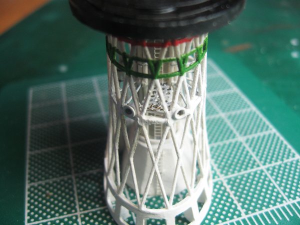
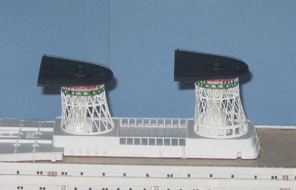
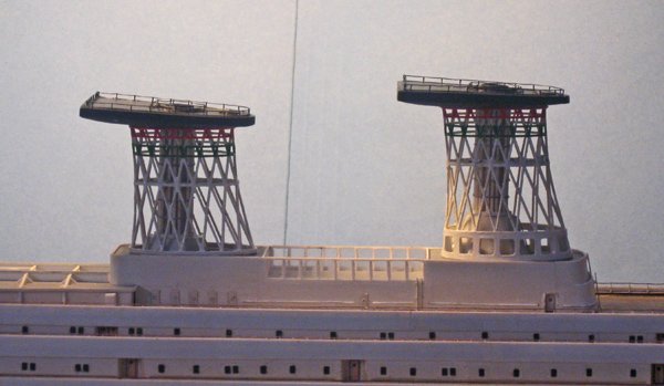
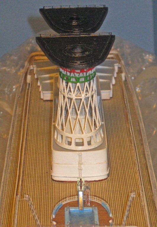
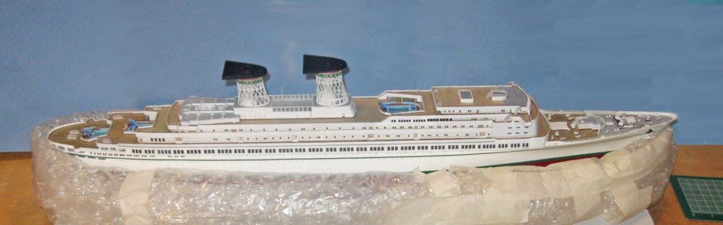
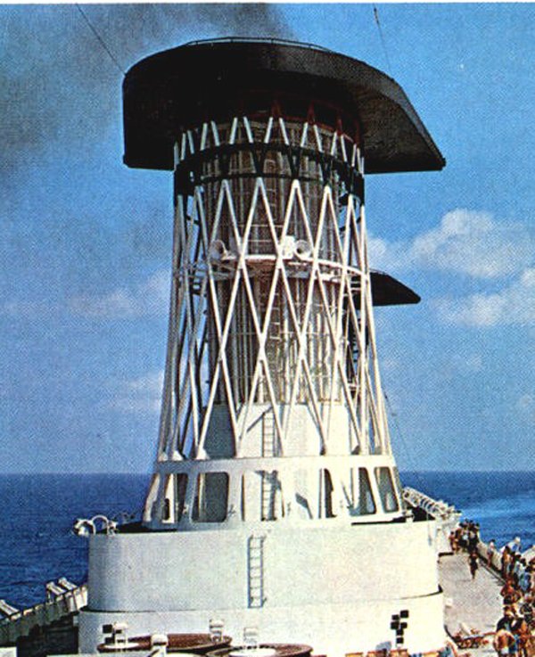
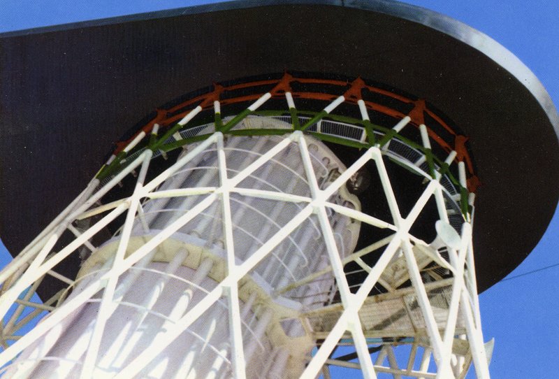
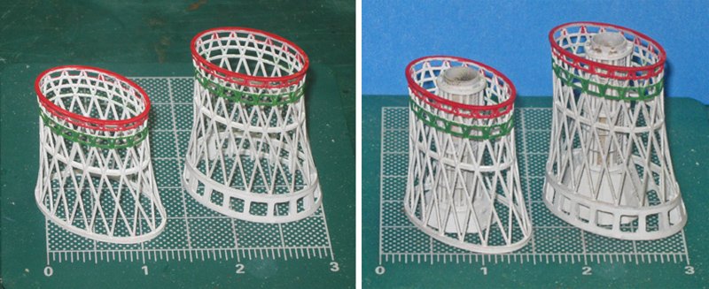
Hi to everyone, and thanks again for the comments and compliments from craftsmen and artists whose work I so highly respect. With the funnel cages and pillars completed, I turned to the smoke deflection caps. There are no plan views of them, but in this photo their shape can be seen. They are wedge shaped with a rounded front. The funnel tube exits towards the front with a raised ring around it. There is a round plate at the front whose purpose I could not determine. Low railings go around the cap near the edge and another railing around the exit plate. The back of the cap has a shallow vee shape. The plans show the cap from the side. It has two portions, an upper one with a constant height, and a lower one that is shaped and tapered to set the upper surface at an angle. The length of the cap was measured and the photo above was adjusted to correct for the foreshortening caused by the camera angle. The adjusted photo was printed out and used as my pattern. Construction began by cutting two plates 2mm thick from hardwood. The lower plate on the left is upside down with the outer ring of the cage marked on it and a hole drilled to accept the top of the pillar. The upper plate, on the right, has a slightly smaller hole drilled to fit a brass tube that slides inside the pillar tube for a secure joint. The lower plate was marked to show how it was to be beveled, while the upper plate got its tube, disk, and cover plate. With the lower plate shaped the two were joined. A bit of hand sanding finished the edges. Some 2-bar railing had its top rail trimmed, then the remaining 1-bar rail was installed as seen in the photos. When the construction was satisfactory the entire cap was painted matte black. The cages and pillars were located and secured to the cap with white glue, locking them in place in relation to each other. Once everything was solid the intersections of the reinforcing ring were drilled to accept 0.12” wire. The holes had to be angled, sometimes pretty severely, so the wires would land on the inner ring around the pillar in such a way that they radiate in a regular pattern from the inner cylinder to the outer oval. The wisdom of the added reinforcement was fully realized and I had no breakage of the brittle cages despite some fairly large machining forces. After gluing with cyano the wires were clipped and the stubs ground flush. With a small brush I reached through the openings in the cage to paint the radial wires white, as shown in the photos. In the forward funnel two grommets stand in for the foghorns, while a painted piece of pierced brass sheet makes up the walkway. The cages got a touch-up with white acrylic paint and a final coat of gloss clear finish. Here is how they look, set in place, the photo taken using a flash with the blue background set a little too close. Here they are backlit. And here is the look from dead ahead. It is not quite the Times cover, but pretty close With the pools and funnels in place the ship is starting to round into final form. Next, the two masts that define the height of the ship. Until then, be well. Dan
- 287 replies
-
- 15
-
-
- michelangelo
- ocean liner
- (and 1 more)
-
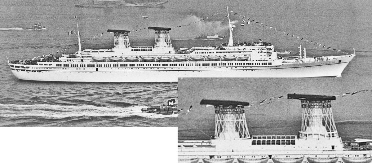
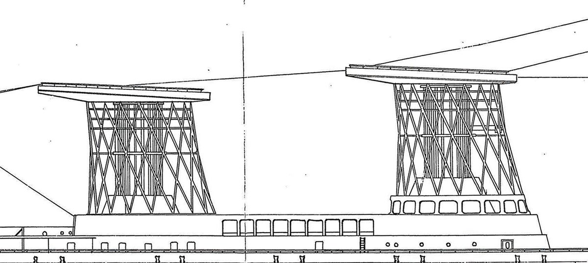
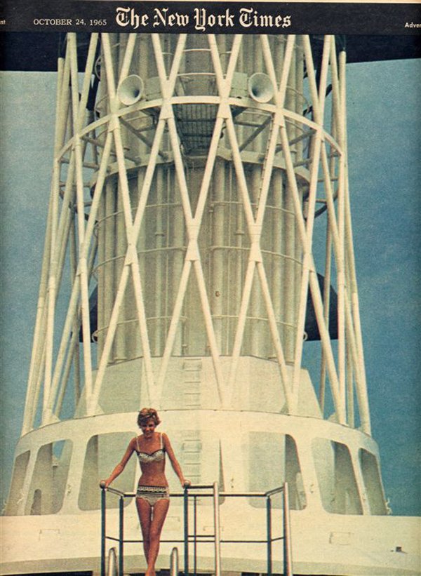
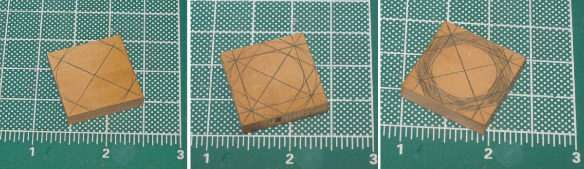
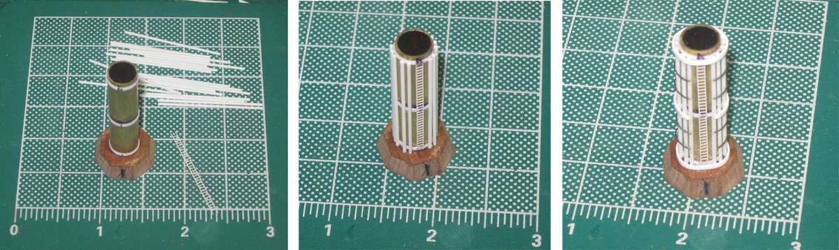
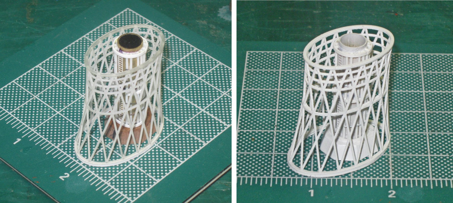
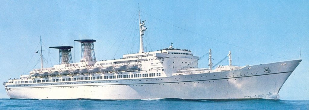
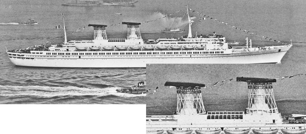
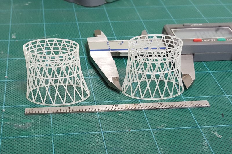
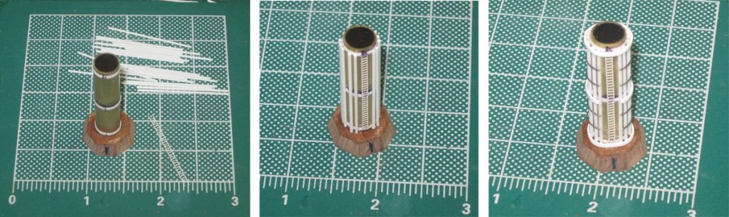
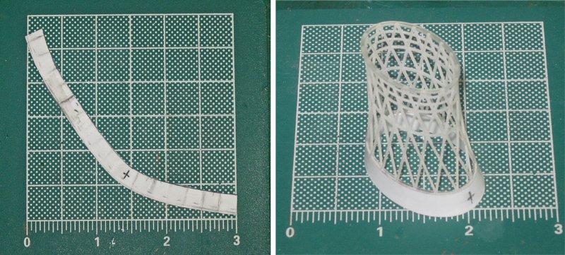
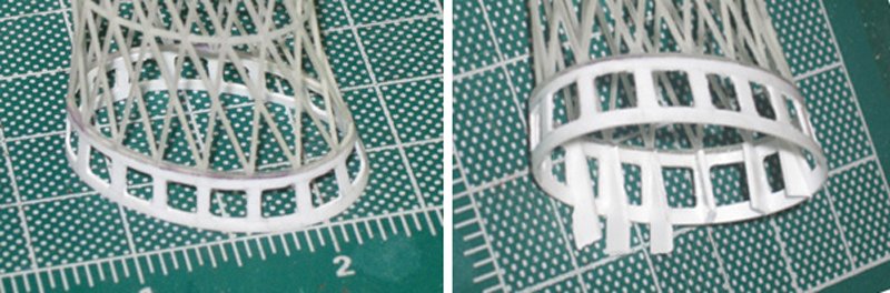
Hi again to all – Thanks for all the support and compliments. I am glad that you are enjoying this voyage. With the pools finished, I turned to the next detailed subassemblies, the funnels. As you can see, they are some of the most visually important elements of the ship. In profile they dominate the center of the ship, especially because of the dark caps that contrast with the rest of the white colors of the ship. In the enlargement you can see that there are three major components to the funnels – the latticework cages, a central tube, and those smoke protection caps. The plans show that the two funnel cages, tubes and caps are identical, but the forward funnel has a pierced skirt that lifts it higher than the aft one, requiring a taller base for the funnel tube. The caps angle forward about 2.5 degrees and have low railings on top. This color photo reveals that the forward funnel has a ladder up the front face of the octagonal base and up the forward line of the central pillar. Painted bands with the red and green colors of the Italian Line circle the cage just under the cap. Two foghorns are mounted just above the reinforcing ring about halfway up the cage. From underneath you can see the bars that connect the cage to the pillar from each six-way intersection at the level of the reinforcing ring. Also, the central pillar is not a simple tube, but has a number of smaller tubes circling it, all confined by a number of wires. Between the foghorns is a grating platform, probably to service the horns. These details are all seen clearly in the photo from the cover of the New York Times magazine section. It also shows that the bottom skirt is supported on the back of each vertical upright by a triangular buttress. The details are, of course, the only things that interest me in the photograph. . . . As reported earlier in the build log, the cages were 3-D printed by Hexnut. The first set was just a bit small. My bad, not his. I worked out the proper dimensions and he redid the design and had them printed by Shapeways. They were even more perfect than the first set. Thanks again, Bob. I started construction with the central pillars, and with the bases first. From the photographs it is clear that they are octagonal with sloped sides. The aft one is 6mm tall, the forward one 12mm. To make the aft octagon I cut a hardwood piece into a square on the Preac saw. Using simple geometry I located the center, then marked out a circle just to the edge of the square. Using a 45 degree square I drew lines at each corner tangent to the circle. This defined the octagon (a). I measured the slope from the plans and drew a smaller concentric circle. Using 90 degree and 45 degree squares a concentric octagon was marked out (b). To keep everything clear I darkened the waste wood (c). Then it was easy to cut off the corners on the band saw and to slope the sides to the top line using a disc sander. The forward one was made in a similar fashion, just taller. The central pillar began with a brass tube 10mm in diameter set into a shallow drilled hole in the center of the base. Three rings of 0.01”x 0.04” strip were wrapped around the tube and secured. The location of the middle one had to match the reinforcing ring on the cage, which is why the base had to be built first (a). A photoetched ladder was cut and fitted to the front center of the tube before 15 rods of 0.035” were set up and glued to the three rings around the tube (b). Solid rings top and bottom and an interrupted one in the center secured the vertical rods, and four restraining wires further detailed the pillar (c). This construction fit nicely inside the cage and needed only a little tweaking. Once I was happy with it, both the pillar and the cage were given their first coat of spray primer. The skirt for the forward funnel began with a paper pattern. Between the oval shape and the changing flare there was no way that I could predict what it would look like. Small pieces of translucent tape were applied to the bottom of the cage and flared as needed. The inner line was marked at the lower edge of the cage, and the center of the front was marked with a cross. The tape was carefully stripped off and applied to a piece of card. The inner line was cut and tested against the cage. Once I was happy with it, a line was drawn defining a strip 6.5mm wide. It forms a very strange shape (a). This was transferred to 0.03” sheet and cut out, fitted and glued to the cage. The bottom edge was lightly sanded so it sat flat and firm (b). With the solid skirt in place the 16 windows were marked out with 1mm rings top and bottom and verticals coming down from each lower joint on the cage. Each opening was first drilled out in the center, then carefully whittled close to the lines with a fresh blade in my knife. Needle files finished the work (a). Oversized tapered pieces of 0.03” strip were glued to the verticals with white glue, then the joint was strengthened with cyano on each side. When everything was dry the excess was cut off. You can see three finished buttresses with three more being installed (b). Once they were all in, the bottom of the skirt was again gently sanded so everything would sit flat. I knew that I wanted to include the rods from the cage to the pillar if I could. Gentle experimentation convinced me that the cages were not strong enough to survive the stresses of drilling holes at each 6-way intersection. I therefore added a reinforcing strip of 0.02” x 0.04” behind the ring. With it in place and after being primed, the color bands were carefully painted on (a). So here are the two components of each funnel as they will fit to each other. The bars cannot be installed with them not fixed to each other, and will have to wait until they are mounted to the cap (b). Next, the caps will be constructed and the funnels assembled. Be well. Dan


- 287 replies
-
- 17
-
-
- michelangelo
- ocean liner
- (and 1 more)
-
Tom - Boy does that bring me back. The only ship model I made as a kid was a plastic Bounty, which was with my father. Years later the Bounty was the first wooden kit I chose to build. There was a Polaroid of me standing proudly next to it, but it has long since disappeared. Thanks for the memories. Dan
- 1,348 replies
-
- 2
-
-
- constitution
- model shipways
- (and 1 more)
-
Hi Dan - Just catching up, and really like how she is coming along. The joinery on the deck beams and ledges is top notch, and the stove presents a very realistic appearance. Well done. I do suggest that you replace your gratings. Their contrasting color makes them a visual focal point, but they are quite out of scale and shape. If you can't make them yourself (and there is a nice how-to Shop Note from Don Spruel in the current Journal), then there are several suppliers who can meet your needs. You may have to shim the surrounding coaming to get a tight fit, but the result should be up to the very high level of craftsmanship of the rest of your work. Best of success. Dan
-
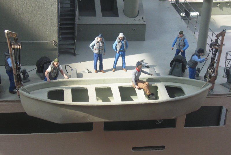
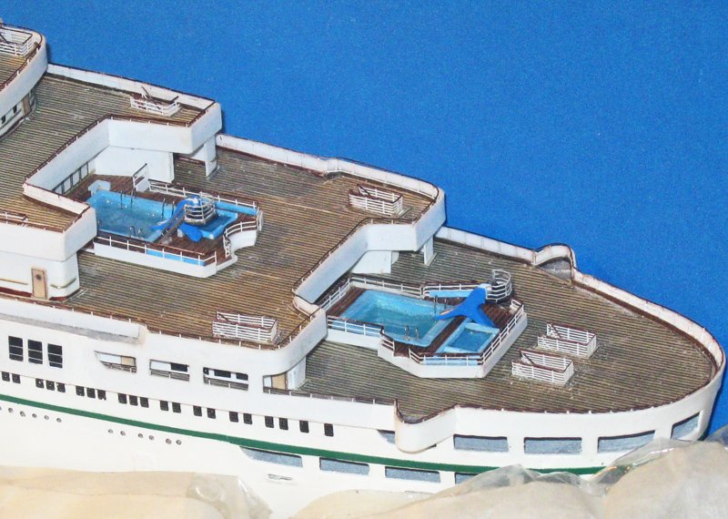
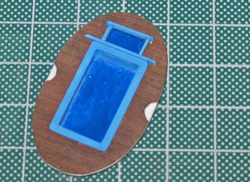
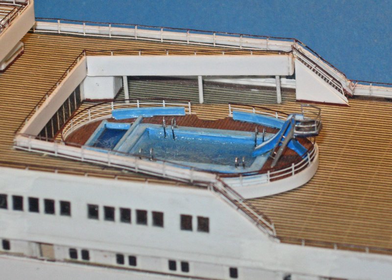
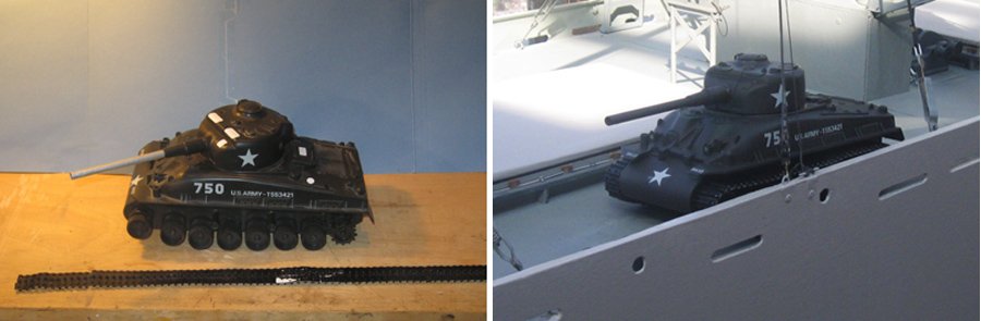
Hi all - Thanks Marc, Jan and Michael for your comments, and to everyone for the likes. Here are a quick couple of photos of some progress on both the Michelangelo and the Zebulon Pike. First, the lower two swimming pools on the liner. Their shapes do not appear anywhere on the plans and had to be derived from the photographs. The techniques and materials are the same as for those of the main pool, just slightly reduced in size. And here are two final photographs of the crew at work on the Pike. Two crewmen are tensioning the chains that hold down the Sherman tank, while a number of men are engaged in a lifeboat drill with the boat swung out. One of the docents at the museum took a look and said, "Just like the real thing. Two men working and five others standing around watching . . . " Happy Pesach, Good Friday, and Easter to all who celebrate the holidays, and best wishes for a great day to everyone else. Dan
- 287 replies
-
- 12
-
-
- michelangelo
- ocean liner
- (and 1 more)
-
Hello, sir - I am glad to find your build log. It is really nice work in this scale and with a steel hulled ship. I will certainly keep it on my watch list. What is the type of large cannon in your last photo. That is a very large drop in diameter from breech to the muzzle that I have not seen before. Best of success with the project. Dan
-
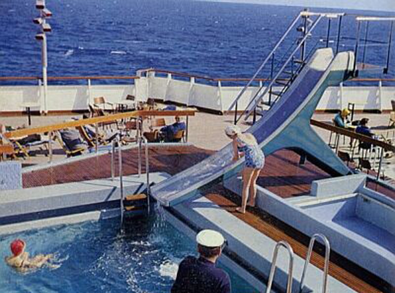
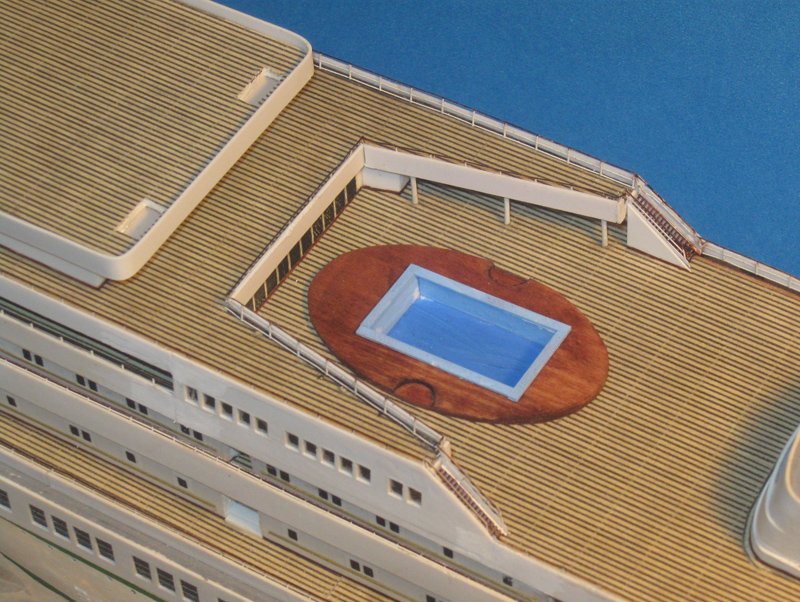
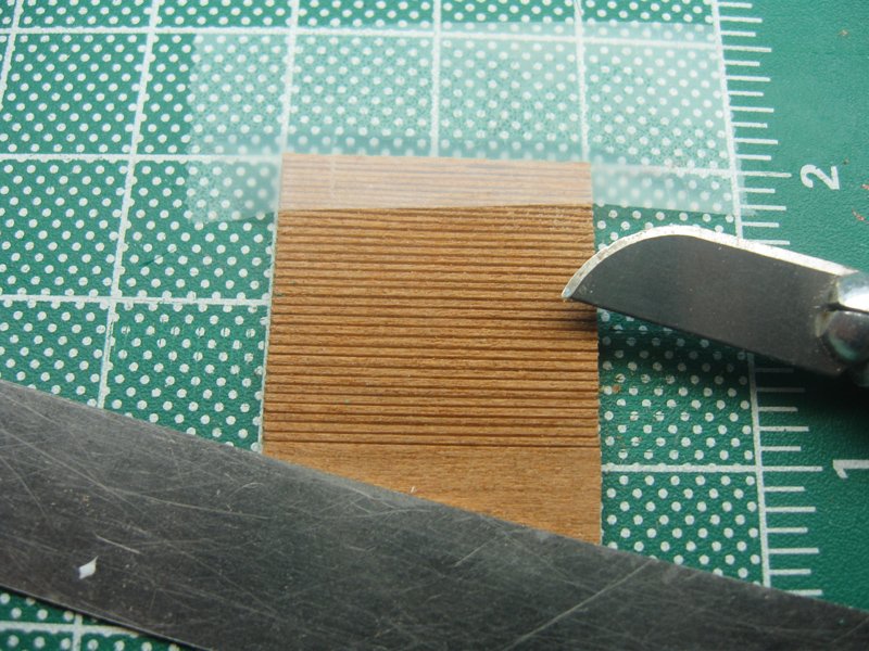
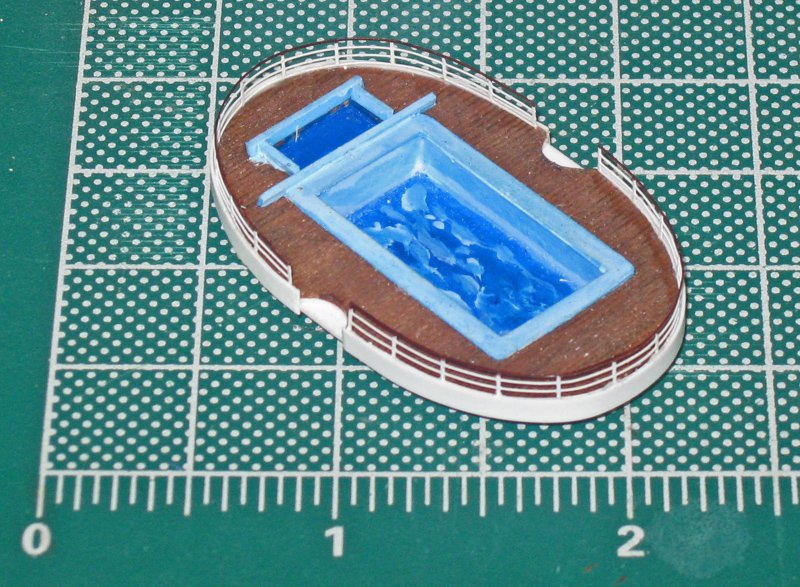
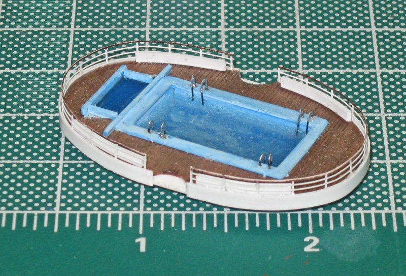
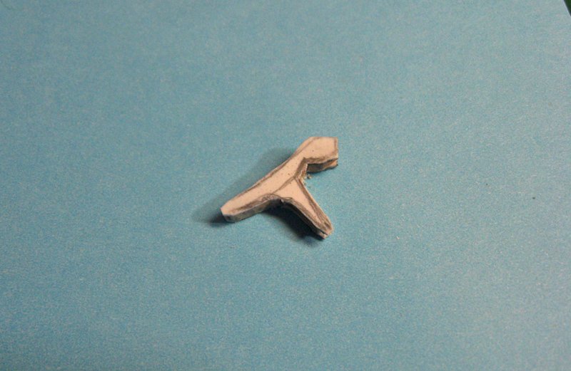
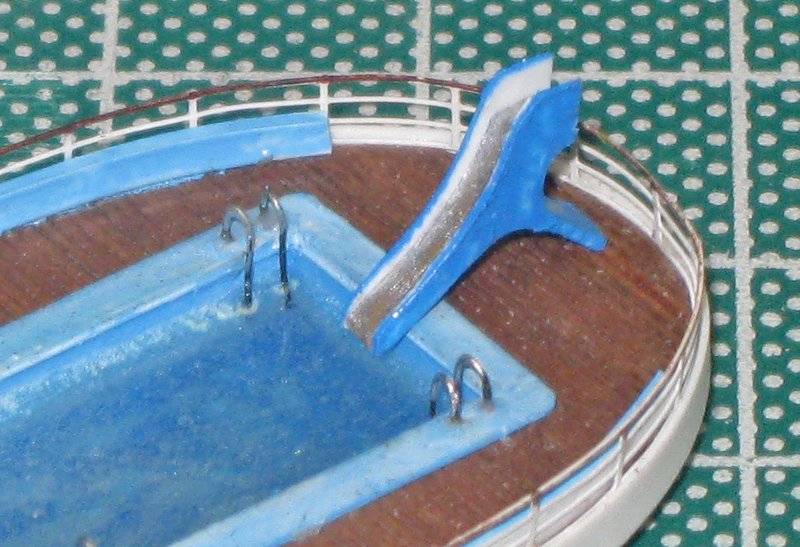
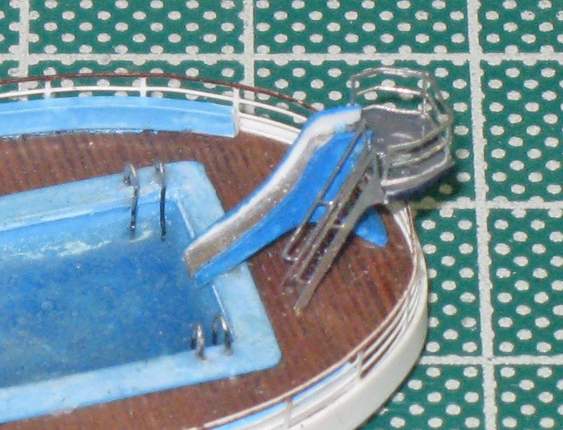
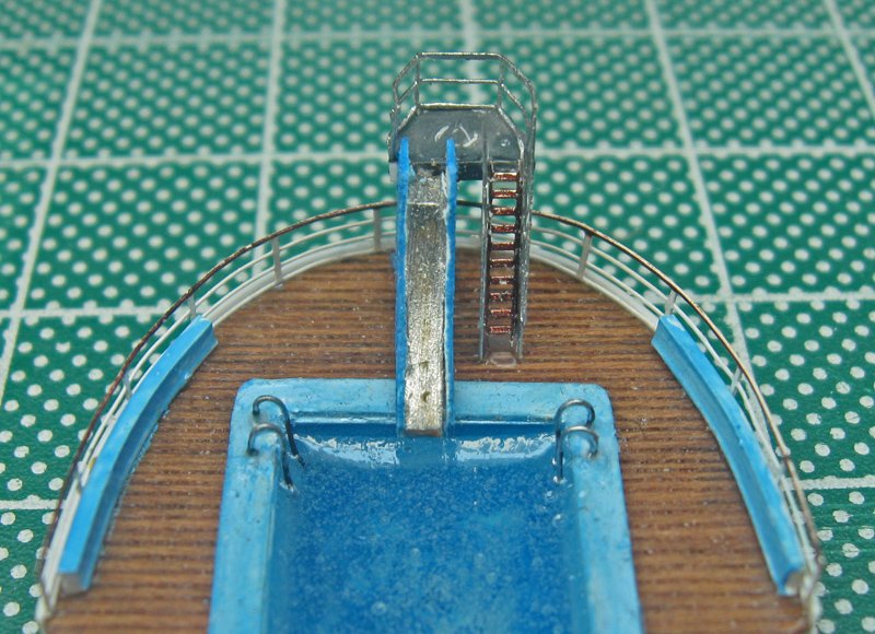
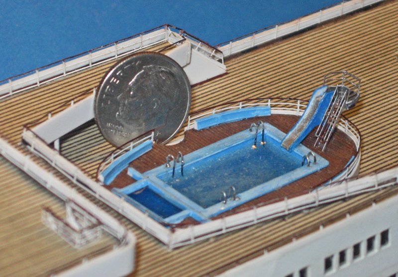
Hello again to all. So, back to the Michelangelo. The ship's structure was completed last time and I began on the various detailed subassemblies. Since I already did a mock up of the main pool, I started with that. Here is the best color photo of the pool that I could find. It is a bit low resolution, but looking carefully, it appears that the pool deck is raised two steps above deck level and is built of dark red planks that run athwartships. The light tan areas come and go in the photos, and are probably removable mats. There is a railing all around with solid benches along some portions of the deck edge. There are four stainless steel ladders into the pool. The slide is in the center, with its stairs to the port side. The slide is a simple curve with raised edges. It is supported on one angled leg and the edge of the pool. The photo below is of the slide from the Promenade deck, but as far as I can tell all three slides are identical, except that this one has the slide to the starboard side. There are kiddie pools for each large pool, but they all different. Information from several photos had to be combined to get their final shapes and details. Here is the mock up that I started with. Actually it is the second one, the first did not merit a photograph. This deck color is reasonably good, but the grain runs the wrong way and the half moon steps are too deep, so it had to be replaced. The pool insert needed some cleanup and repainting, but was salvageable. The final deck was built up of three layers: a bottom lift of 0.030” styrene with only the space for the main pool cut out. The second was a layer of 0.020” plastic topped with a scribed sheet of cherry veneer. They had cutouts for the main pool, the steps, and the kiddie pool. This gave those features some depth. The veneer was scribed by first cutting it to a rectangle on the table saw. It was taped to a cutting mat printed with 12 rows of dots every half inch. This is 1/24 inch, or almost exactly 1mm. A metal straightedge was laid along one row and a light pencil line was drawn across the wood. The graphite from the pencil was tattooed into the veneer by scribing along the line with the back of a #10 blade. With a coat of clear finish it came up to a nice warm red tone. The layers were stacked and glued. The main pool was sanded and repainted, then dropped into its space and secured there. The kiddie pool had sections of two different heights surrounding it. They were painted off the deck and installed. The vertical edge of the deck did not appear clearly in any of my photographs, so I went with a simple strip that created a lip around the deck surface. PE railings were cut, bent and fitted to the lip, then secured in the usual way. Some random streaks of lighter blue were squiggled on the bottom of the pool. I find that this looks a bit more convincing under water. Here is the pool filled with 5-minute epoxy water. The ladders are 0.011” wire colored with non-buffing aluminum enamel. They were simply bent to a narrow ‘U’ and inserted into holes picked out with a needle and then hand drilled. I tried several different ways to get rungs on the ladders, but nothing worked to my satisfaction, so they were left off. The side benches have been curved and installed and are ready for painting. The final element for the pool is the most complex, the slide. It started with a rough cutout like the one below. The curve of the sliding surface was sanded into it and it was painted with the aluminum before sheets of thin plastic were superglued to both sides. The plastic was cut away to leave a raised lip around the sliding surface and a higher raised portion at the top to push off of. The rest of the plastic and the wood was ground off until the “Y” shape of the slide emerged. Then it was painted a slightly contrasting blue. The back of the slide was notched for a polygonal platform whose shape was seen in another photograph, topped with a steel railing. A narrow style of PE ladder was bent up, painted and installed. After looking at this photo I realized that the handrails did not meet properly, so some very careful bending was needed before they did. With that done, here is the slide and aft end of the pool. I think it matches reasonably closely to the first photo in this log. I do see, though, that during handling and construction the brown has come off the lower handrail. After touchups the pool was temporarily dropped into place in the deck. It is not perfect, but I am not unhappy with how it looks. And here is my second favorite President, come to check on the progress. With his approval it was removed and placed in secure storage. More soon. Dan

- 287 replies
-
- 20
-
-
- michelangelo
- ocean liner
- (and 1 more)
-
Happy to pull up a chair and enjoy another of your builds, especially one based on archaeology. Best of success. Dan
- 263 replies
-
- 1
-
-
- nave tonda
- round ship
- (and 2 more)
-
Hi Marc - They really are repaying the efforts you put in. Once painted they should look superb. If you are still doing casting, could you just fill the impressions or maybe scrape away the excess resin above the impressions before it hardens? Then you might have a lot less waste to remove. I don't know how it would affect the curing process. Dan
- 2,696 replies
-
- 3
-
-
- heller
- soleil royal
- (and 9 more)
-
Hi Tom - The Connie is coming along really well. Would love to see her at Joint Clubs if she can travel. Here is a belaying trick that works for me. For each line I remove the selected belaying pin and run the line through the open hole in the pinrail. Replacing the belaying pin traps the line firmly, but allows adjusting and tensioning as long as you want. When you are ready, give the excess rope a few turns around the pin and secure it. With a rope coil on top it will look very realistic. i have a longer explanation with a drawing in a Shop Note in a recent NRJ, but I don't have the issue number handy. Hope that helps. Dan
- 1,348 replies
-
- 2
-
-
- constitution
- model shipways
- (and 1 more)
-
Hi Roger - Not really sure. I know that the Long Island Railroad goes from Grand Central Terminal in Manhattan to Great Neck, which is the closest large town, but I doubt if you can walk from the station to the Academy. Uber and Lift will have cars that can take you. However you get there, you will have a great time. When you are in Brooklyn, check out the museum at the Brooklyn Navy Yard. Another small gem (not to mention two of my pieces) with interactive exhibits on the history of the Navy Yard. I know that busses take you right there, the entrance is on Flushing Avenue, where you get right in and do not have to go through the security gate to the Yard itself. Dan
- 287 replies
-
- 7
-
-
- michelangelo
- ocean liner
- (and 1 more)
-
Thank you all for your comments. I did have a lot of fun on this unusual project. I hope that the visitors also get a chuckle, as well as learning a few things about our brave sailors who kept the Atlantic lifeline open in some of the darkest hours. If you live in or are visiting the New York area, this little gem of a museum is worth the time. Many ship models, from an exquisitely detailed 15 foot long SS Washington to a cabinet of 1:1200 miniatures, as well as a huge interactive tabletop exhibit of a convoy at sea. Rooms of navigation equipment and videos of sailors' recounting their experiences. Contact them at museum@usmma.edu Phone: 516-726-6047
- 287 replies
-
- 6
-
-
- michelangelo
- ocean liner
- (and 1 more)
-
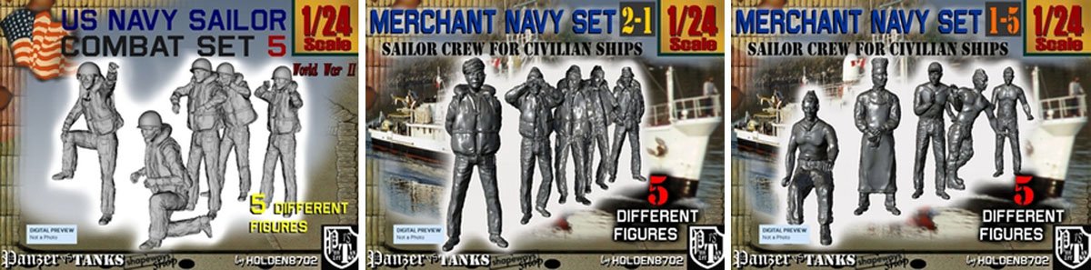
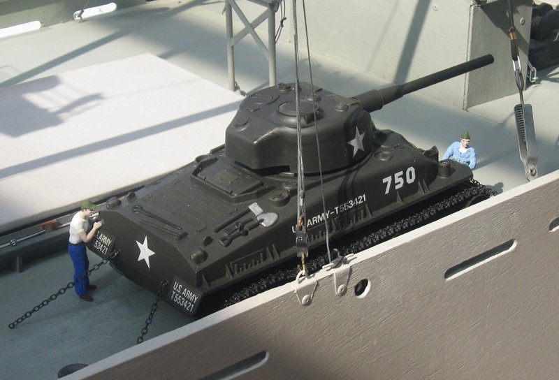
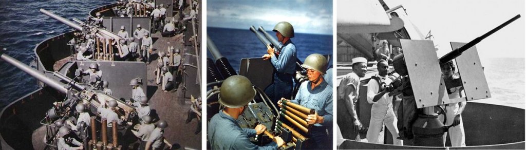
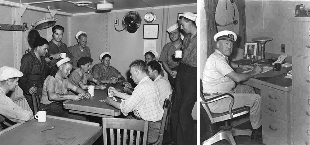
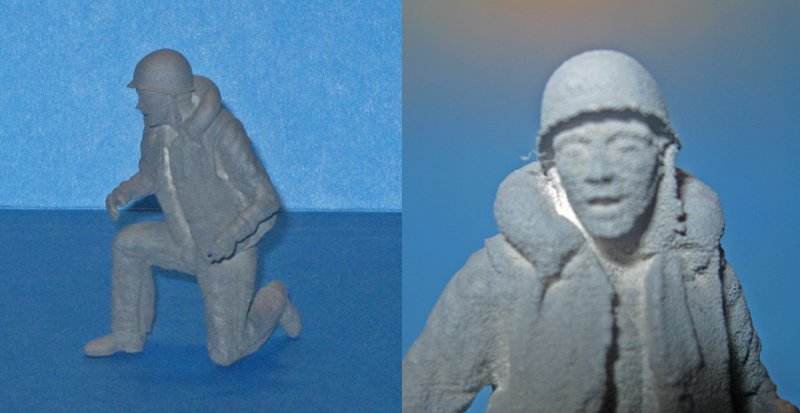
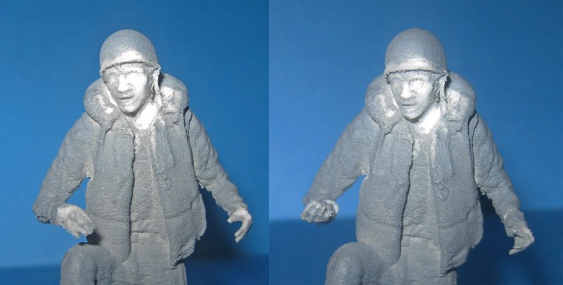
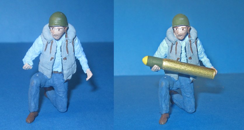
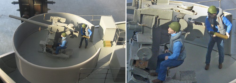
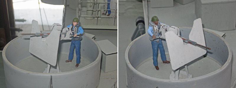
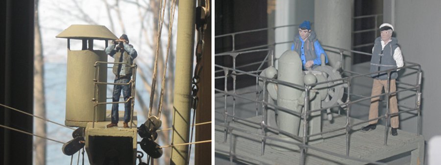
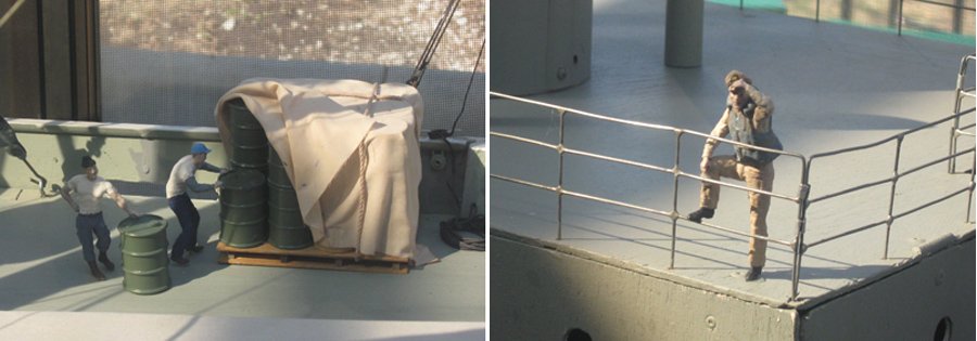
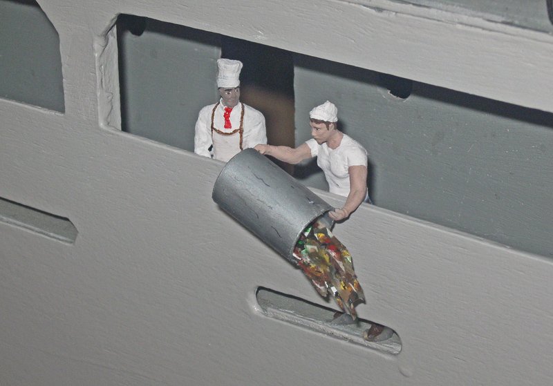
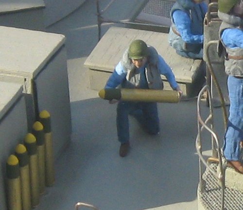
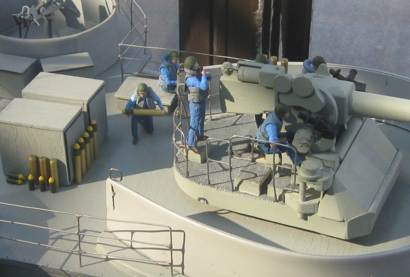
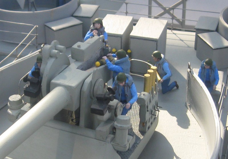
Hi again to all - Here is the second and final installment of this little build log. Hope you enjoy it. With the model and bases polished up, I could move to the fun part – populating it with people. The vision of Professor Smith was to make the Pike display more ‘hands-on’ and interesting for the school age groups that visit the museum. The idea was to have a number of vignettes around the ship that would show both the civilian crew and the naval armed guardsmen in realistic settings. The internet quickly turned up a number of wartime photographs of Navy men servicing the guns. Here are a few. Photographs of civilian crewmen were harder to find, other than sterile, posed shots of a ship’s entire crew, all of them scrubbed up as if for their class photo. I did round up a few, like these motley sailors at cards, and the captain at his desk. The figures themselves were sourced from Shapeways. I knew of them from the funnel cages for the Michelangelo, but was surprised at how many offerings were in their catalog when I searched for “1/24 navy figures”. Dozens of poses, uniforms, helmets, and caps. Here are a few. The guardsmen came from their combat sets, with helmets and life jackets. The crew from the merchant navy sets, some with lifejackets, some without, and even one in the apron and hat of a cook. The figures are produced in two quality levels, coarse and fine, with the latter being a good deal more expensive. The financial parameters of the contract mandated the former. Although they are described as ‘soft’ by Shapeways, when they arrived I found that they are printed in a hard, brittle white plastic with just a little give. Following the instructions, they were cleaned of oils and primed. Here is the figure of a kneeling loader for the 5 inch gun. In the close-up you can see how rough the surface actually is, especially on the skin areas. Some details, like his helmet brim and strap, have extra lumps of plastic, while the strap is connected to his neck with an extra web. Using knives and grinding bitts the extra bumps were removed and the helmet strap was cut free. A wire wheel was used to smooth the flesh of the face and hands, leaving the white plastic showing. To perfect the pose the hands were sliced off at the wrists and rotated. I painted the figures with craft acrylics in basic colors. Little attempt was made to be hyper-realistic with shading and washes, trusting to the eye of the viewer to supply those textures. The 5 inch shell was turned to military specifications from a birch dowel on my drill press/lathe. Although all alone and in closeup the figure appears crude, but on deck I think it worked out pretty well. And here is the 5 inch gun with six guardsmen crewing it. Notice that there are separate propellant charges and warheads, as well as some joined as one shell ready for use. It was while researching the gun and its ammunition that I discovered another little-known detail of Wally’s model. All the way to the starboard side of the gun there are three shells upside down in a fixture. It turns out that this is the fuse setting machine. The fire control officer in control center would wire down the proper setting to the machine, and the crank was turned till the shell setting matched. This substantially improved American rate of fire. Here is the 3 inch gun at the bow with a gunner and loader. Even in a fairly close-up shot the Shapeways figures stand up to examination. The 20mm Oerlikons are served by gunners whose arms were surgically removed and positioned to grasp the handles of the model’s guns. One is African-American, as were many sailors during the war, watching out warily for the enemy. The civilian crew is on lookout as well. The helmsman stands ready at the wheel with his eye on the gimballed compass and the old man’s eye on him. On deck a few crewmen muscle oil drums onto a pallet while the mate shades his eyes and keeps them honest. I’m still adding touches. There will be several figures involved in a lifeboat drill, and additional deck workers. As an extra I rounded up a 1/24 scale Sherman tank, a broken Radio Shack R/C toy. After removing the incorrect spotlight, muzzle brake, switches and markings, their holes were filled and painted. The broken tracks were repaired and reinforced with black fabric tape and the tank set on deck where it will have some crewmen securing it with chains. But whatever other vignettes get built, there is one that is already a hit with the school crowd. At the rail the cook watches while his KP swabby empties a pail full of scratch-built garbage. Hope that this was an entertaining diversion. Now back to the Michelangelo. Dan

- 287 replies
-
- 16
-
-
- michelangelo
- ocean liner
- (and 1 more)