shipmodel
-
Posts
941 -
Joined
-
Last visited
Content Type
Profiles
Forums
Gallery
Events
Everything posted by shipmodel
-
 Michael - I never even considered that solution. Brilliant! Unfortunately, I have already laid up the hull lifts, so I am committed (or should be) at this point. Mark - Who told you my secret? 😉 Dan
- 287 replies
-
- 3
-

-
- michelangelo
- ocean liner
- (and 1 more)
-
Hi guys - Thanks for all the likes and compliments. Yes, Druxey, building an ocean liner is an exercise in repetition. The first few were fun. The recent ones more of a chore. I have developed some techniques and have been the beneficiary of some wonderful gifts from friends in the community. But still a chore. Fortunately I get some commissions to build or restore sailing ships so I can keep those skills sharp. Michael, I suggested that I build two half models and mount them on front-surface mirrors, but this was rejected in favor of the bizarre bi-polar model. Well, it's their dime, so they get to make the decision. Be well Dan
- 287 replies
-
- 3
-
-
- michelangelo
- ocean liner
- (and 1 more)
-
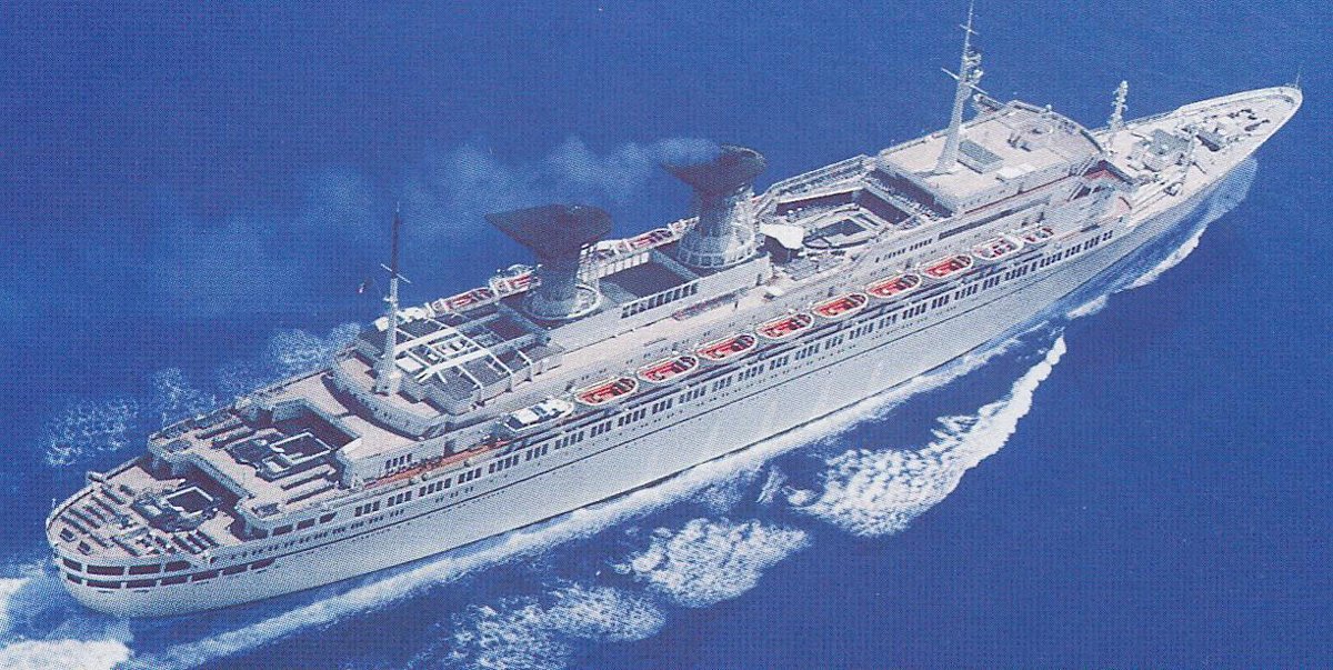
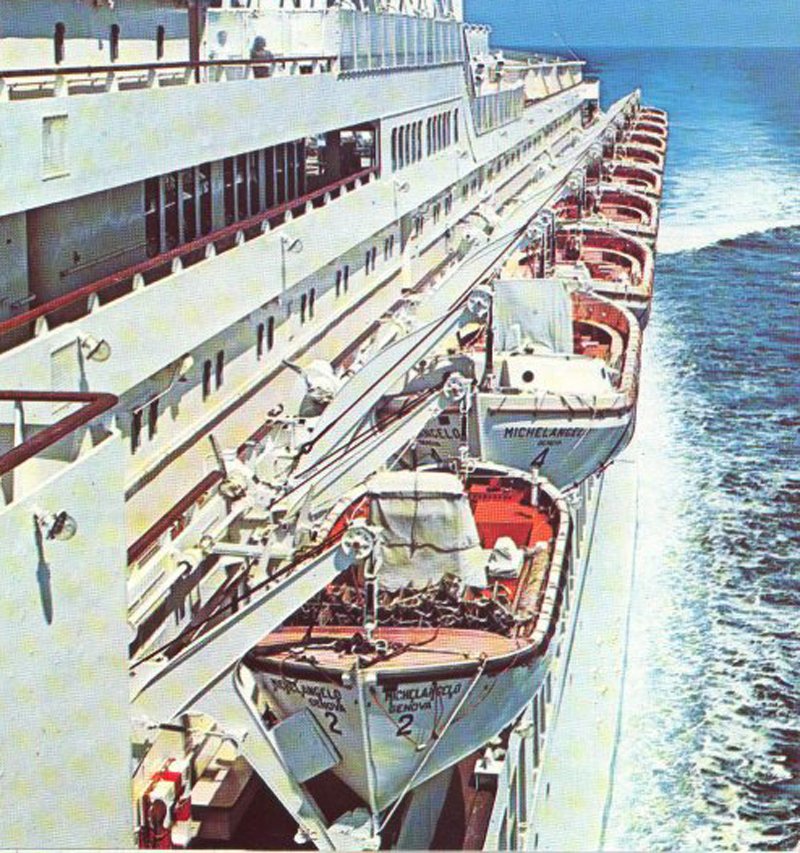
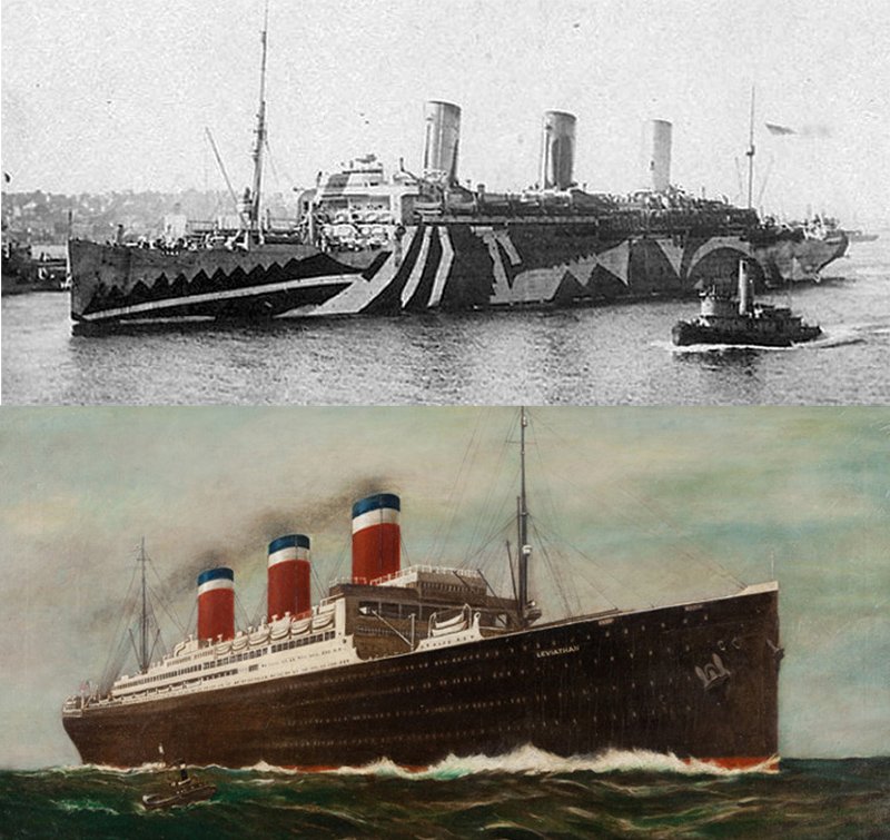
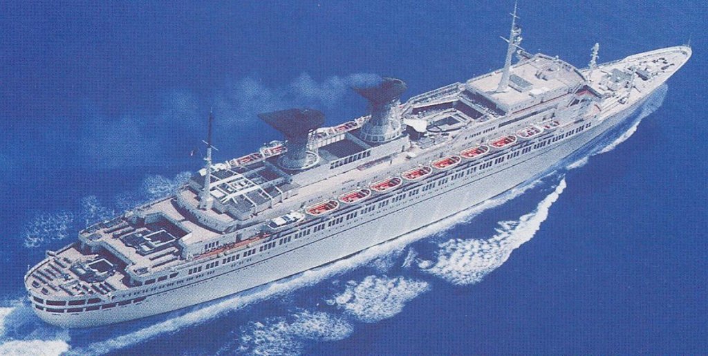
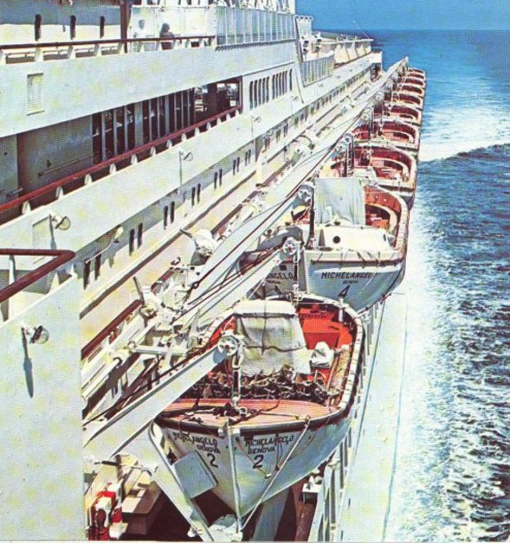
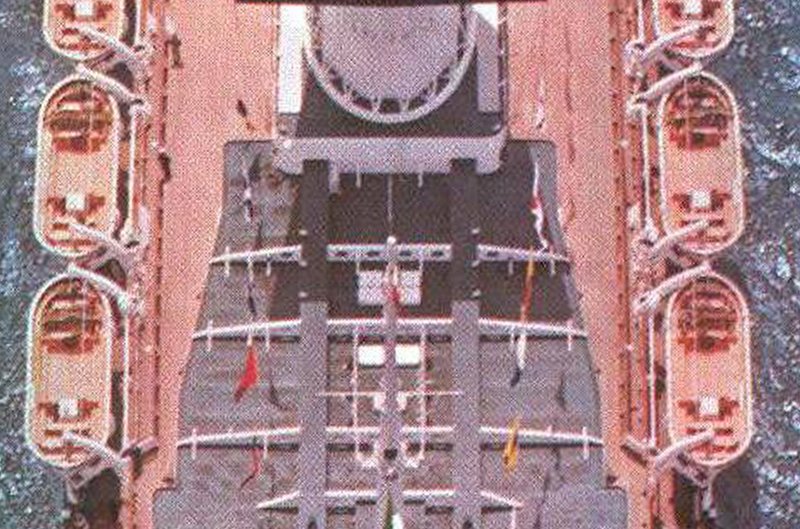
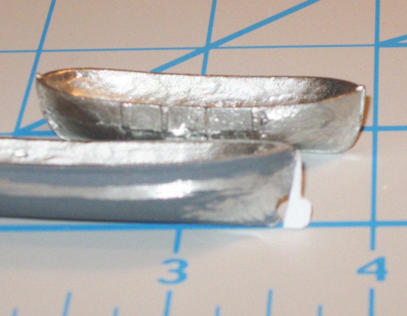
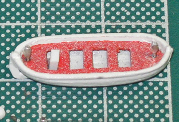
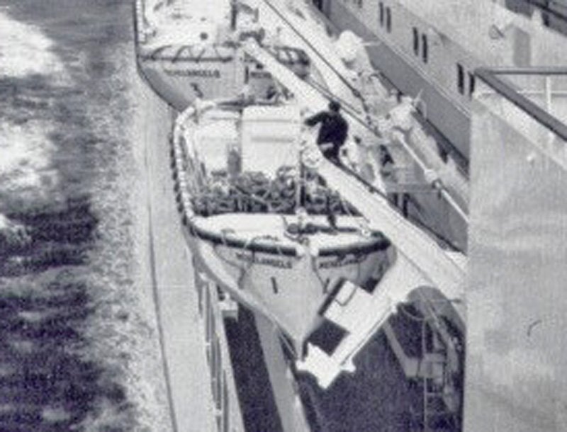
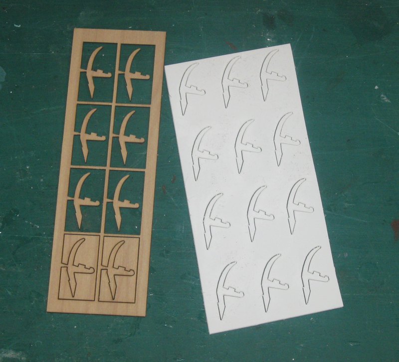
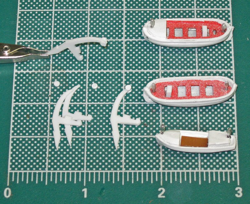
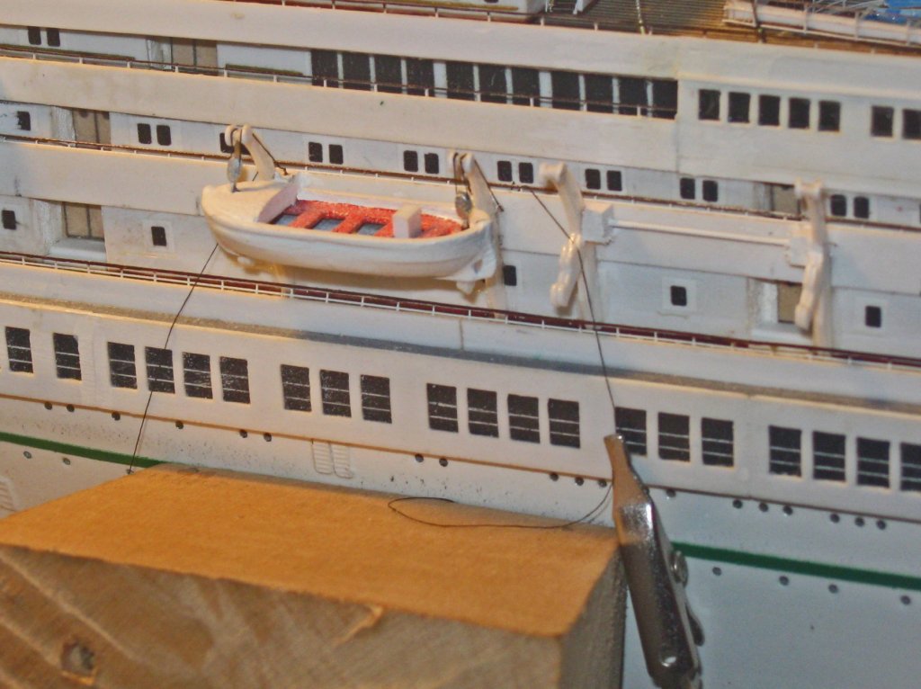
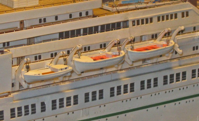
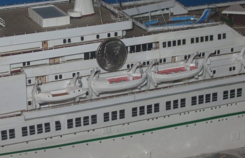
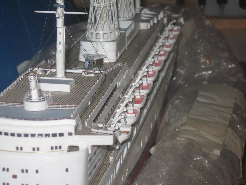
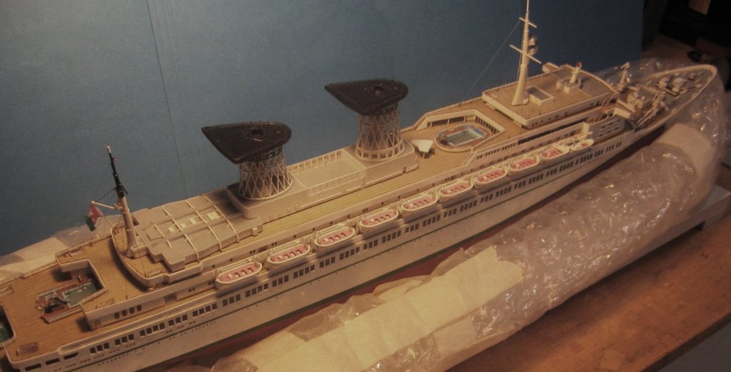
Hi again to all. Many thanks for the likes and compliments, as always. It has been a while since my last post on this build log. Summer means more outdoor activities with family and many more outdoor chores, so less modeling. Someone should do something about that. 😋 This build has also been hijacked by another project. I have been hired by the US Merchant Marine Academy museum to build 7 models in the next 4 years, and I have been doing the research and laying the groundwork for them. I will, of course, be writing and posting build logs as I go along. The first of these will be quite an unusual model. It will be of the USS/SS Leviathan (1914), which in her day was the largest ship in the world. She was a troop ship during WW I and an ocean liner afterwards. The troop ship was painted in a wild ‘dazzle’ camouflage, while the liner was dressed in the red-white-and blue livery of the US Lines. The unique thing about the model is that I am directed to build the port side as the troop ship, with its guns, military style boats and dozens of life rafts, etc. The starboard side will be done as the ocean liner with the guns removed and civilian style boats. Down the centerline, where there were added lookout posts, rangefinder platforms and other structures, I am to cut them in half, make them hollow and paint the edges red to show the differences. The scale is 1/16”=1’, so the model of this 950 foot ship will be just under 5 feet long. Oh, and I only have 9 months to complete it. Wish me luck. I did get some work done though. I ended the last installment of the log with the construction of the bow cargo cranes. Next I turned to the lifeboats. With the Michelangelo, as with all ocean liners, the boats are an important visual element. In this illustration you can see how their bright orange interiors contrast with the general white colors of the ship. There are several types of boats shown, including a motor launch, although I cannot decide if this is a grainy photograph or a painting that may differ somewhat from the actual ship. In this next photo there is no launch, although the first boat is smaller and the second has an enclosed cabin at the bow. The boats hang from fairly simple one arm davits of a design that I have not seen before. From overhead I can see that the davits are joined to each other with a shaft that ends in large fittings which are probably the winches for the boat falls. Toward the aft end of the boats there is a white blocky element which must be either the engine or the control station for the boat. The boats started life as appropriately sized pewter castings from Bluejacket. With some refining they made excellent fittings. First the sides were smoothed to remove the bumps which are meant to be safety lines, I guess. The sternpost was straightened and concave hollows ground to let the water reach the propeller cavity. A plastic rudder was roughly cut and secured with CA, then refined in place. The insides of each boat was ground thinner, as was the cast thwart insert. After gluing it in, the whole boat was primed and painted white. Then the thwart piece was painted a bright safety orange. A short piece of plastic rectangular rod was set in for the engine. Lift blocks were made from Bluejacket 2mm castings. Their becket ends were cut off and their eyes were drilled out at the other end. A wire was looped through the eye and secured in each hole at the ends of the boat. This photo shows the danger of macro lenses. I had to go back to straighten the engine block and touch up the paint. The speckled look is not a mistake, though. Well, not much of a mistake. The original orange was much too bright, even though it was the correct color. For model purposes the intensity had to be tamed. I opted for a light mist of spray paint from a distance. The speckles are not individually visible without magnification unless your nose is an inch or two from the model, so the result is acceptable. Nonetheless, the next time I would probably choose a thin wash of translucent white or grey. The davits turned into a problem. Here is my best photo of their shape. They have a curved vertical arm with two flat pulley at the top. About halfway down there is a support arm that holds the keel and has a padded block for the boat to rest against. None of the commercial houses had anything close, and I needed 40 of them, all identical. Making so many identical fittings proved to be beyond my skills, so once again I turned for help to my friends who do laser cutting. Charlie Zardoz and Chuck Passaro are two of the most generous members of our community and they have my sincere thanks. I first marked out and cut a master davit from plastic. It turned out to be 22mm tall, about 7/8". I took that photo with a macro lens and exported it into CorelDraw, where I drew the outline of the shape. I sent this out and had laser cut copies created in both wood and plastic. The wooden ones were just the right thickness, but unfortunately there was a weak point at the base of the support arm where the grain runs vertically. Even strengthening the wood with hardener only helped a bit. The plastic ones were strong enough, but were too thin. In the end two of the plastic davits were glued together, with two punched discs to represent the pulleys. The davits were secured against the deck house on the Boat deck 25mm from their partner. They were joined by a .020” brass bar seated in two small blocks mounted to the inner faces of the davits. Each boat was hung with .003" fly tying line that began in each block, ran up and over the inner pulley, through the lift block on the boat, up and over the outer pulley, and then through a hole in the bulwark that led behind the rail. Small clips held tension on the lines until the height was adjusted, then everything was secured with CA and the excess line cut off invisibly behind the railing. Here are the forward three boats on the port side. The forward boat is slightly smaller and hangs just a bit lower than the rest. PVA glue holds the boats to their support arms and everything is really quite secure. And for scale, here is FDR about to board the middle boat. Here is the entire port side run of boats. I wish I had more depth of field for a better photo, but you get the idea. And here is the starboard side. I think it matches up pretty well to the illustration of the ship at the beginning of this post. Only a few final details and it will be ready for launching. I will report in again soon. Till then, Be well Dan
- 287 replies
-
- 18
-
-
- michelangelo
- ocean liner
- (and 1 more)
-
Hi - You certainly have a large challenge in front of you. Whenever I am approached to restore a hobby-built kit model, I always ask "How much do you love the model and the modeler?" In your case your love for your grandfather and his work is quite evident. That settled, there is a huge amount of work to be done, but it is not hopeless at all. Taking it one step at a time is the way to go, just like building the kit in the first place. If you do go forward, I recommend that you get "Ship Modelers' Shop Notes, vol. II" from the NRG shop. I included a specific section on restorations. Rob Napier and others give a good introduction to the skills and methods used. Rob has a longer article in the Journal which you can get, and he has written a book on his restoration of an antique museum model. I am always happy to help out with general questions or specific problems. Don't worry about my time. Second only to building ship models I love talking about them. Contact me through this website or my email at shipmodel@aol.com Best of success Dan
-
Beautiful work, Michael - Comparing the current photos with the first ones, the amount of work, and its quality, are stunningly apparent. Congratulations. Dan
- 749 replies
-
- 8
-
-
- albertic
- ocean liner
- (and 2 more)
-
Beautiful work, Ken - Love how she is coming out. Dan
-
Hi Michael - Just stumbled on this while surfing MSW. You are doing amazing work, given the pictures of what you started with. Actually, I know this model. I did some pre-sale restorations on the Seamans' Church Institute collection when they moved from lower Manhattan to Port Newark in New Jersey. Some of the models were then sold through Bonham's at that auction in 2011. I did not work on the Albertic. It was one of the gems of the group, but it had been in a case so it did not need repairs. I was at the auction, but did not bid on this lot, needless to say. Quite a bit above my price range, and much too large for my NY apartment. I am so glad that the restoration is in your capable hands. I will continue to follow until you are done. Be well Dan
- 749 replies
-
- 6
-
-
- albertic
- ocean liner
- (and 2 more)
-
Beautiful work, JD - I especially like how the flags and pennants came out, especially the Maryland one. Dan
-
Hi Eric - Just got back from vacation and saw this interesting discussion. I do see your issue, which is a planking question and not one of internal structure. Since I have limited experience with river steamboats, but trying to think as a shipwright of the period and location, I would want to know a bit more about the building of the Arabia. Was she built for luxury travel, or was she more of a rivergoing 'truck.' If so, she would have been built as quickly and as cheaply as possible. This points me more towards A, which has the simplest, most economical use of medium length straight planks and wider tapered off-cuts. A more high-end ship might have had a more decorative planking for the guests to stroll along. Also really enjoyed reading your research and planning blog. Dan
- 599 replies
-
- 5
-
-
- sidewheeler
- arabia
- (and 4 more)
-
Hi Marc - Beautiful carving work, and a very closely matching pair. But if you only used the best master, and doubled the number of castings, wouldn't they all be identical? One of the pair is just rotated 180 degrees. Dan
- 2,699 replies
-
- 3
-
-
- heller
- soleil royal
- (and 9 more)
-
Hi Marc - Progressing nicely. Congratulations. I understand that there are 'odorless' cyano glues out there. They are said to be much less irritating. Maybe worth tracking some down. Dan
- 2,699 replies
-
- 3
-
-
- heller
- soleil royal
- (and 9 more)
-
DN Iceboat by MikeR - FINISHED
shipmodel replied to MikeR's topic in - Build logs for subjects built 1901 - Present Day
Really nice work. I can already see her gliding across the frozen Hudson. Dan -
Like everyone else I am very impressed with your Chebec. Truly fine artistry. Give yourself a pat on the back and relax with your favorite beverage. Congratulations! Dan
- 692 replies
-
- 5
-
-
- eagle of algier
- chebec
- (and 2 more)
-
Beautiful work on the dolphins, Marc. They will really set off the rails. Can't wait to see how they work out. Dan
- 2,699 replies
-
- 3
-
-
- heller
- soleil royal
- (and 9 more)
-
Hi Mark - Yes, I have the PE kit. Unfortunately, my efforts to date have not been very good. Something to work on in the future, as you say. The learning is never ending, but that's one of the major reasons that I work in this field. Dan
- 287 replies
-
- 3
-
-
- michelangelo
- ocean liner
- (and 1 more)
-
Hi Nils, John - Thanks to you both. Ultimately, I am satisfied with how the cranes look on the model, especially if I take off my glasses. I know that there is a solution out there, but I suspect it lies in the field of fine jewelry or by using circuit board manufacturing techniques. Neither one was affordable in time or treasure for only 12 blocks. Perhaps one day . . . Dan
- 287 replies
-
- 4
-
-
- michelangelo
- ocean liner
- (and 1 more)
-
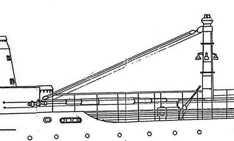
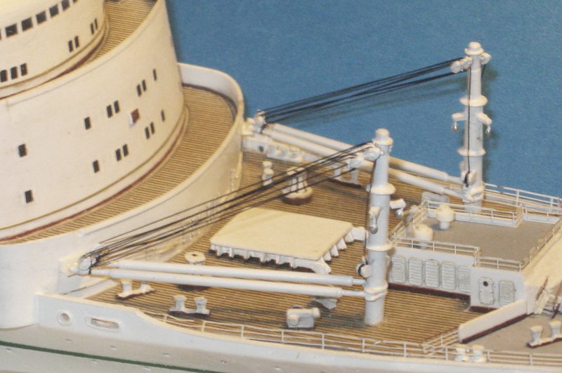
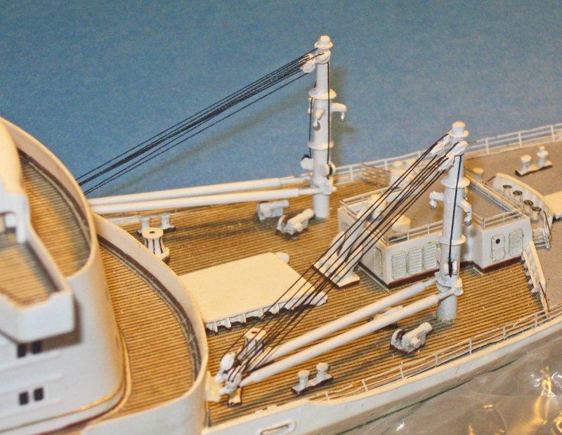
Hello to all the following group, and everyone who looked in. Thanks for the many likes and compliments, and especially for the comments and critiques. I will try to keep up the level of work. This will be a short post, despite the month since my last one. I took on a restoration project that was time sensitive, so I had to put the Michelangelo on the siding while that train went through. The major work this time was on the cargo cranes that sit on the forward deck. Here is the section of the plans for the cranes, lacking a lot of the details that can be seen in the two photos of the uprights. As you can see, they are not the simple posts that many are, but have numerous fittings, rings, winches and flat blocks. Notice particularly the three spotlights hanging from horizontal supports. Each element was reproduced as closely as I could, given the small scale of the model. The post and the booms were assembled from telescoping brass tubes with the top of the post turned from a small piece of hardwood dowel. The boom pivot fittings, rings, winches, and the light supports were cut from styrene. The lights themselves are small drops of epoxy on wire posts. The biggest problem turned out to be the cable blocks. In the close-up you can see why. The set consists of two upper single blocks attached to the post. Attached to them is a smaller single block on the inner side, with a double block for the outer, heavier boom. Note how flat they are. I tried numerous ways to reproduce them without success. They are just too small for my abilities. I tried punched plastic discs, but could never get them to line up right, and attaching them to the post and to each other was impossible. Cast metal blocks were better, but the attachment lugs broke repeatedly. Ultimately I settled on 2mm wood blocks that I am used to working with from sailing ship rigging. Once painted white I think they came out acceptably. The cables are 0.006” polished black thread which contrasts nicely with the dominant white and tan color scheme. The final touch was to give the spotlights a touch of silver on their bottoms to represent the bulbs. I can see that there are some paint chips and railing sections that got bent by my clumsy fingers while working on the cranes, and these will be addressed before the next posting. Until then, be well. Dan
- 287 replies
-
- 24
-
-
- michelangelo
- ocean liner
- (and 1 more)
-
John - A very nice rendition of an unusual subject. Thanks for taking us along on the journey. The Hunley project sounds like an interesting one as well. I look forward to following along. Be well Dan
-
Hi JD - Just read through your log. She is coming along very nicely. It was enlightening to see how your skills, techniques, and attention to detail grew and progressed as you worked through the multitude of problems that building a top level ship model entails. Congratulations! I will be following along from now on. Dan
-
Ben, not to worry. I am enjoying learning something new about my ship. I enlarged the photo of the lights to see if there were any indications of color. It was taken in daylight with the lights off, but they actually look sort of maroon. Not much help there. If there is a final consensus, I will go with that. Otherwise, something with plausibility will be fine. Dan
- 287 replies
-
- 3
-
-
- michelangelo
- ocean liner
- (and 1 more)
-
Guys - I had no idea how those lights were used, but it makes perfect sense. Jack, Pat - I will check to see if there was a regulation covering those lights for ocean liners in the 60's. If that does not pan out, I will go with Ben's suggestion of red/white (silver)/red. Many thanks for sharing the knowledge. Dan
- 287 replies
-
- 6
-
-
- michelangelo
- ocean liner
- (and 1 more)
-
Hi Druxey - Yes, I have the red and green running lights on the sides of the ship. Not sure at all what color the lights on the mast would have been. I was just trying for some visual distinction and interest. Instead of red and green I may give them a touch of silver. Leaving them all white makes them look like indistinct blobs. Thanks for the feedback. Dan
- 287 replies
-
- 5
-
-
- michelangelo
- ocean liner
- (and 1 more)
-
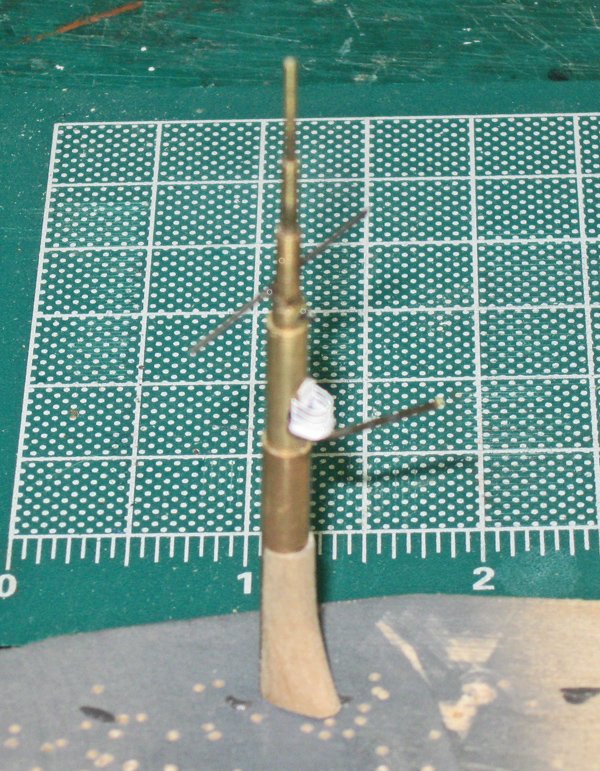
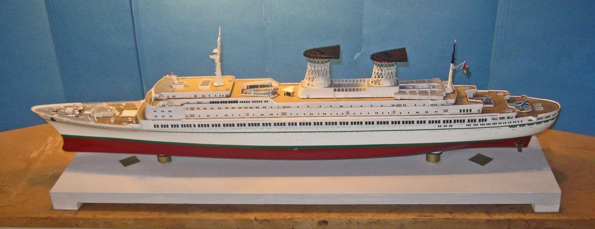
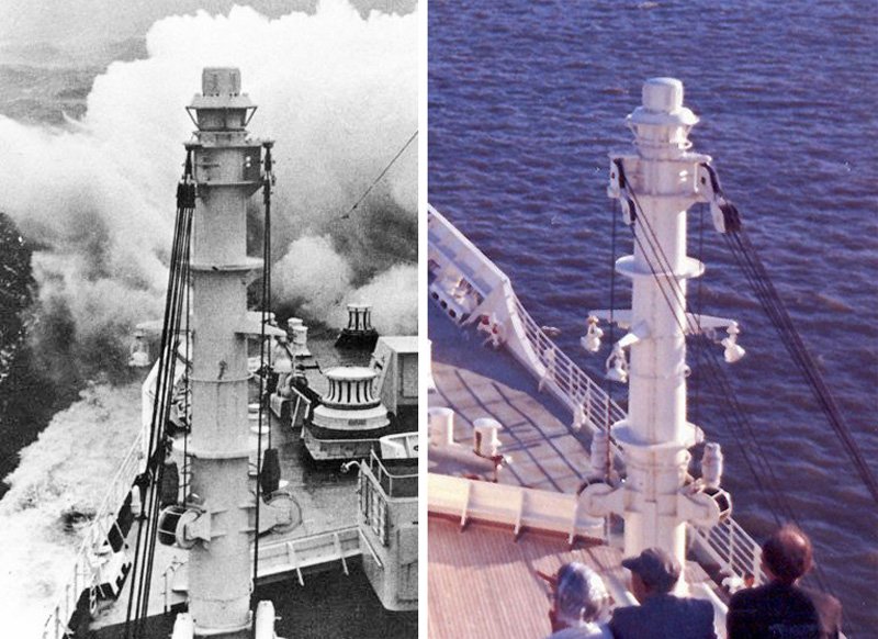
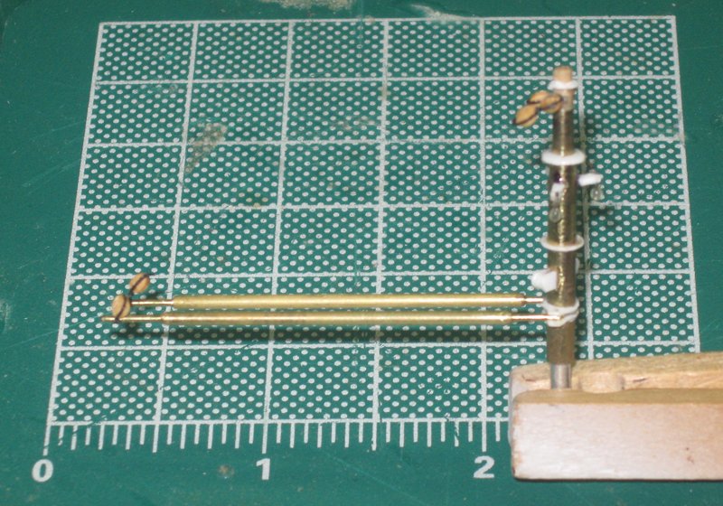
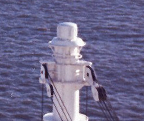
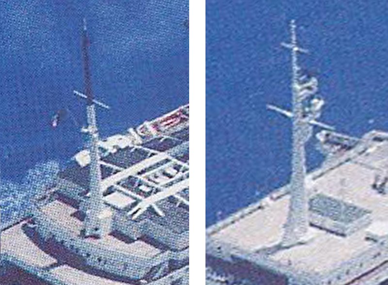
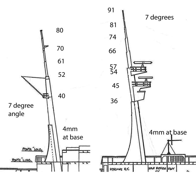
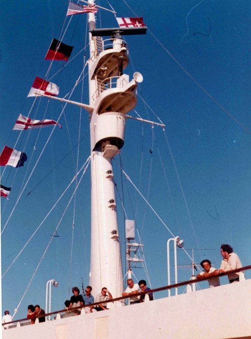
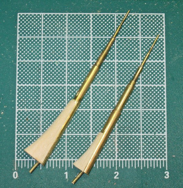
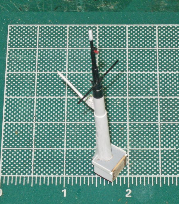
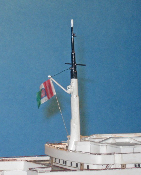
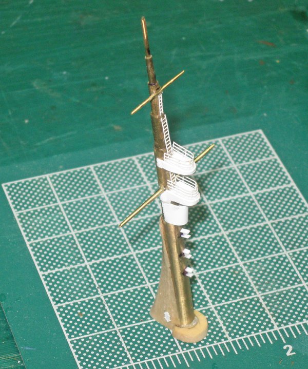
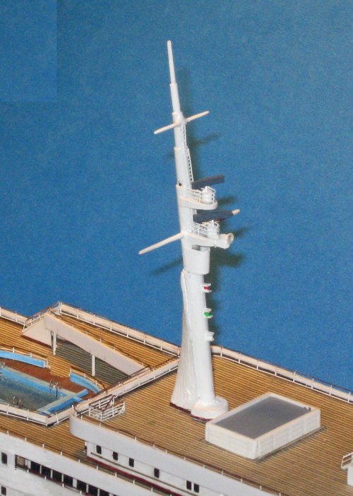
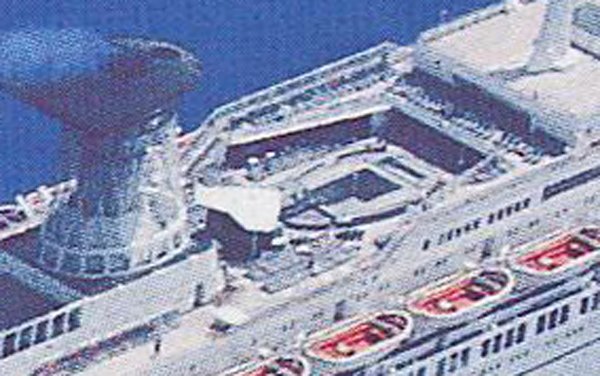
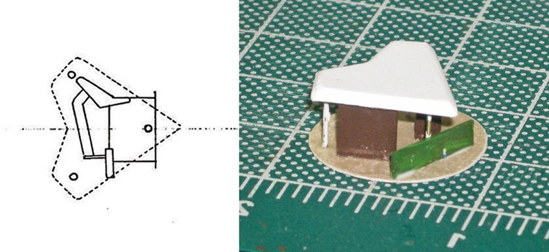
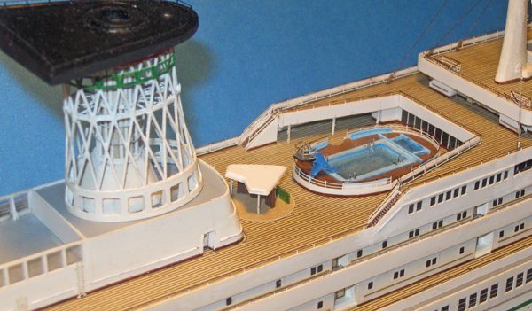
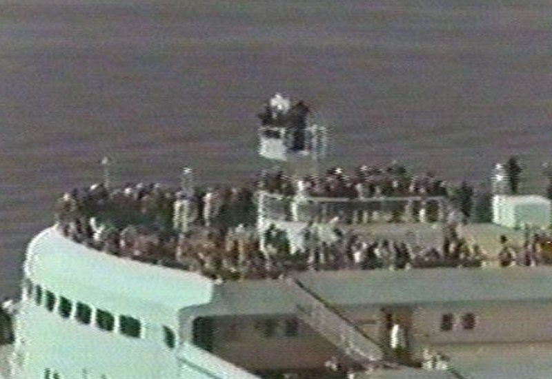
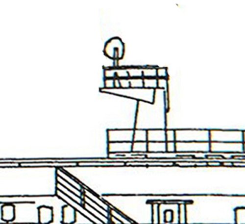
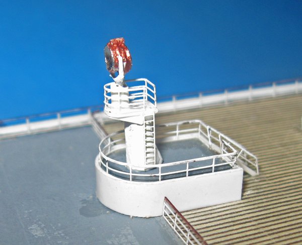
Hi again to everyone following, with many thanks for the likes and comments. A number of you were at the Joint Clubs Conference in New London last week, and mucho thanks also for the compliments from those who saw her in person. Between the last posting and Joint Clubs I did some work on details to get her ready. The first of these were the two masts that define the height of the ship. In these somewhat grainy photos you can see that they are somewhat complicated structures, especially the foremast. From the plans it is clear that they are not simple tapered cylinders, but are built up of telescoping sections. Each has 6 segments of various lengths, starting with a 4mm diameter at the base. Each has a flared support at the base and one or more platforms for radars and lookouts. Photos like the one below showed many of the details, although some still had to be inferred. Here I could see the lookout station, the two railed radar platforms, the two spars, the foghorn, and the three lower lights. Also seen are the several stays, lifts for the spars, radio and flag lines. I attempted to duplicate as much of this detail as I could. The masts began with 5 telescoping thin-walled brass tubes, topped with a final solid rod. Flared support bases were fashioned from hardwood. A 4mm hole was drilled into a larger billet at a 7 degree angle. Wood was removed from the forward side of the hole and the mast tubes were glued in. Then the remaining wood was carved to shape. A brass pin was secured into the bottom for later mounting. Here the aft mast has received its tapered brass spar, soldered into a groove ground into the front face of the mast. The aft face has a small railed lookout platform with a photoetched access door. The ensign staff is soldered into a hole just below the lookout location. (It is a bit out of focus, but I had moved on before I realized this so I could not reshoot it.) The mast was painted according to photo evidence, with the base set into a small deckhouse. After mounting on the ship I added a pre-skewed paper flag using my usual techniques. The lines are 0.006” fly tying threads in black and tan. The stays will be added later, the lower ones through the hole just below the lookout platform. The foremast got its tapered brass spars soldered on, with lookout and radar platforms pieced up from styrene sheet and strip. Railings and ladders are photoetched, as is the access door at the base. The three lower lights are pieced together from very tiny pieces of rod and strip. A wooden piece was also added to the forward side of the base as seen in photos. The foghorn was added and the mast was painted. I do not know whether it is accurate, but I painted two of the lights red and green for some visual interest. The next small detail, although a very visually important one, is the “flying wing” shaped bar that sits between the main pool and the funnel house. Using the plans and various available photos of minimal clarity and detail, I made my best guess as to its layout. Here it is with a green barrier that sets it off from the pool area. Overall, I think it matches pretty well to the first photo. The final detail for this segment is the searchlight platform that rises above the monkey bridge on the Belvidere deck. Here is the best photo of it that I found, with the deck opened to passengers. The plans do not have a lot of detail, but enough to get the proportions and dimensions. The riser was carved from hardwood with a styrene platform and supports. Railings and the ladder are PE brass. For the searchlight itself I found a small metal casting, detailing it with bits of styrene. I painted the body bronze and ground out the forward face to a bright, concave surface. That finished the work that I could accomplish before the Conference, so here it is just before being packed for transport. The lifeboats with their uniquely shaped davits are the only major components left. Getting close to the end. Be well Dan


- 287 replies
-
- 16
-
-
- michelangelo
- ocean liner
- (and 1 more)
-
Hi Tom - Best of success with the semi-retirement and the move. I envy you your future workshop with a view of the lake. Sweet! As for straps, I have had good success - no movement and no damage - by taking some small-bubble bubble wrap and cutting a long, fairly wide strip which I roll into a strap. This is run across the model amidships, maybe just aft of the boats, and held down with washers and screws to the base on either side. This keeps the model from jumping in the base when/if your moving van hits a bump along the road. The strap does not have to be very tight, just firm enough to prevent movement. If you are worried about abrasion from the strap, a small piece of soft cloth along the rails will prevent that. Whatever you decide, good luck and I hope to see your final progress soon. Dan
- 1,354 replies
-
- 3
-
-
- constitution
- model shipways
- (and 1 more)