


Dr PR
-
Posts
2,471 -
Joined
-
Last visited
Content Type
Profiles
Forums
Gallery
Events
Everything posted by Dr PR
-
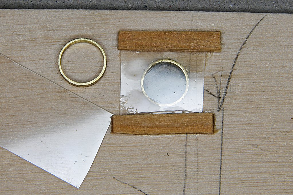
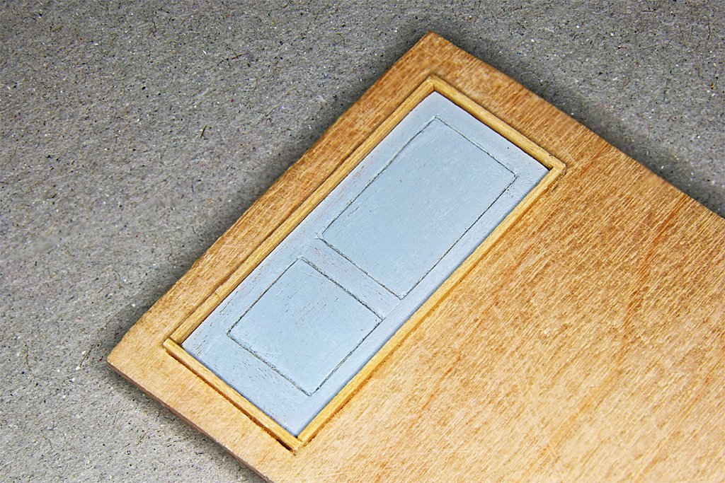
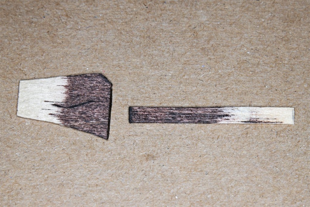
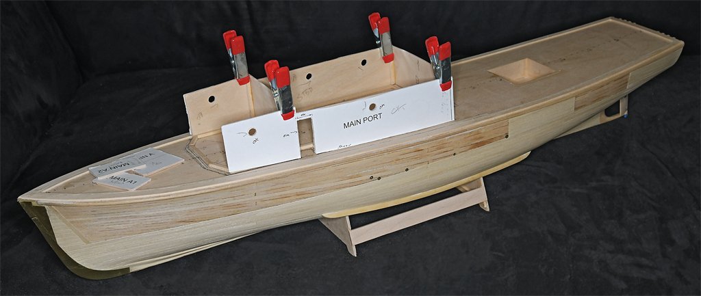
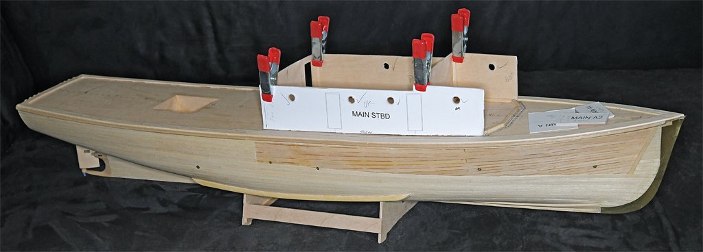
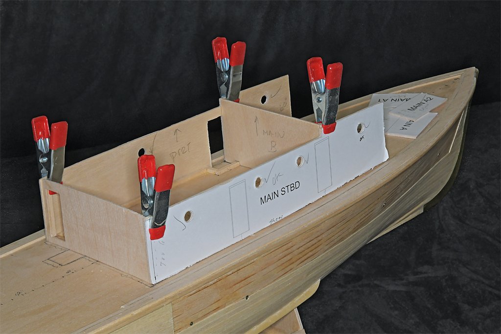
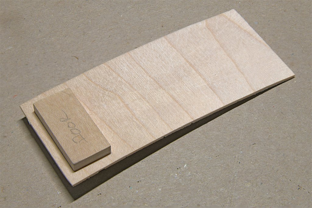
 A bit more progress on the doors and deckhouse. These are the pilot house doors. The door on the left is partially assembled. It is 1/32 (0.0325) inch (0.8 mm) thick pear wood strips and panels glued onto a 1/32 inch thick plywood backing. This is the rough door before sanding and staining. I knew I couldn't create uniform width grooves for the white trim, so I took a hint from small craft builders who needed white grout between planks. I used some 0.020 inch (0.5 mm) white styrene strips. The window is a 0.005 inch (0.13 mm) thick piece of acrylic sandwiched between two thin (>0.015 inch/0.38 mm) rings cut from a 0.28 inch (7.1 mm) diameter brass tube. The inside diameter is 0.25 inch (6.4 mm) or 12 inches at 1:48 scale. The door on the right is finished with Varathane wood stain, in the "Gunstock" color. The pear stains nicely and I like the resulting reddish "varnished mahogany" color. I have been wondering how to get a good mahogany color and this stain works well. All of the door and window trim around the pilot house was mahogany. While rummaging through my wood stash I found a bag of 3.75 x 0.093 x 0.045 inch (95 x 2.4 x 1.1 mm) HO scale railroad ties that appear to be real mahogany! I remember buying these in the 1970s to be used as hull planks for a scratch built ship's boat. These "ties" are a good size for the door and window trim, and the window frames. I was working on the doors while the glue set on the deck house assembly. This assembly is tricky because there are no right angles. The deck house is narrower at the front than at the rear, so the sides aren't parallel. The deck has significant sheer forward but the bulkheads should be vertical perpendicular to the water line. The attachment of the forward angled bulkheads to the side pieces is critical for getting all the other pieces right. I added a lot of interior bracing to make it strong enough to hold up to handling The first attempt to put it together came out too wide, and it didn't fit the house outline framing glued to the subdeck. I had to disassemble the port side and reshape the pieces to fit correctly. I am using Titebond Original wood glue and it can be softened with water and heat. So I soaked the joints and heated them with a hair dryer. It came apart "reluctantly!" The interior bulkheads are just clamped in place at this point. They set the angles where the front and side pieces join.


- 492 replies
-
- 10
-

-

-
- minesweeper
- Cape
- (and 1 more)
-
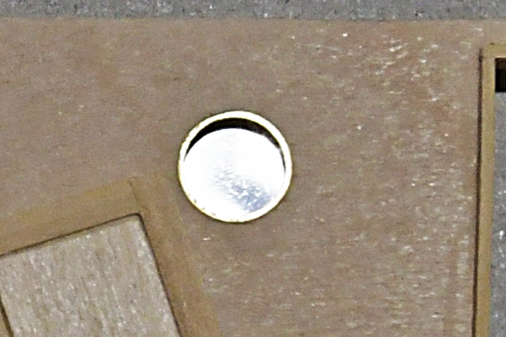
Here is a bit more progress on things that must be done before the deck house parts are assembled. I have cut out the door and air port openings on the deck house sides. Then I stripped off the paper templates, sanded the wood smooth and applied a coating of acrylic sealer. And I made all the weathertight doors except the mahogany doors for the pilot house. This is the prototype door positioned in the after deckhouse bulkhead - with the panels removed and installed correctly! I am using Titebond Original wood glue, and it can be loosened with heat. I used my plank bending/sail making/quilting iron tool as a debonding heater to loosen the glue. The door frames are 1/32 x 3/32 inch (0.8 x 2.4 mm) boxwood strips glued into the opening in the 1/16 inch (1.6 mm) thick plywood bulkhead. Technically the bottom sill should be 0.0026 inches (0.066 mm) thicker than the side and top sills, but with my tools I have no way to produce this. The grooves in the door stand out nicely! The finished door will have a brass door knob made from a small brass nail. I made the air ports with a 1/16 inch (1.6 mm) long piece of 0.28 inch (7.1 mm) outside diameter brass tubing. The inside diameter is 0.25 inch (6.4 mm), or 12 inches (305 mm) at 1:48 scale. These were sawn off the end of the tube a bit longer than needed. Then they were pushed into a hole in a piece of 1/16 inch thick plywood and filed down until they were as long as the thickness of the plywood. It would have been easier and quicker with a lathe! \ I glued squares of 0.005 inch (0.127 mm) thick clear styrene on the inside of the bulkhead, with additional scrap wood pieces to hold them in place. I have considered adding an additional 3D printed piece on the inside of the air port that is shaped like the metal inside cover and painted the typical US Navy interior puke green. Whether I actually do that remains to be seen. But if I do they really won't be seen at this scale, so why bother?
- 492 replies
-
- 9
-
-
- minesweeper
- Cape
- (and 1 more)
-
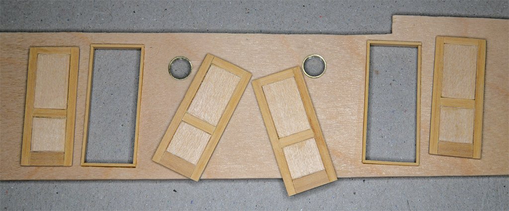
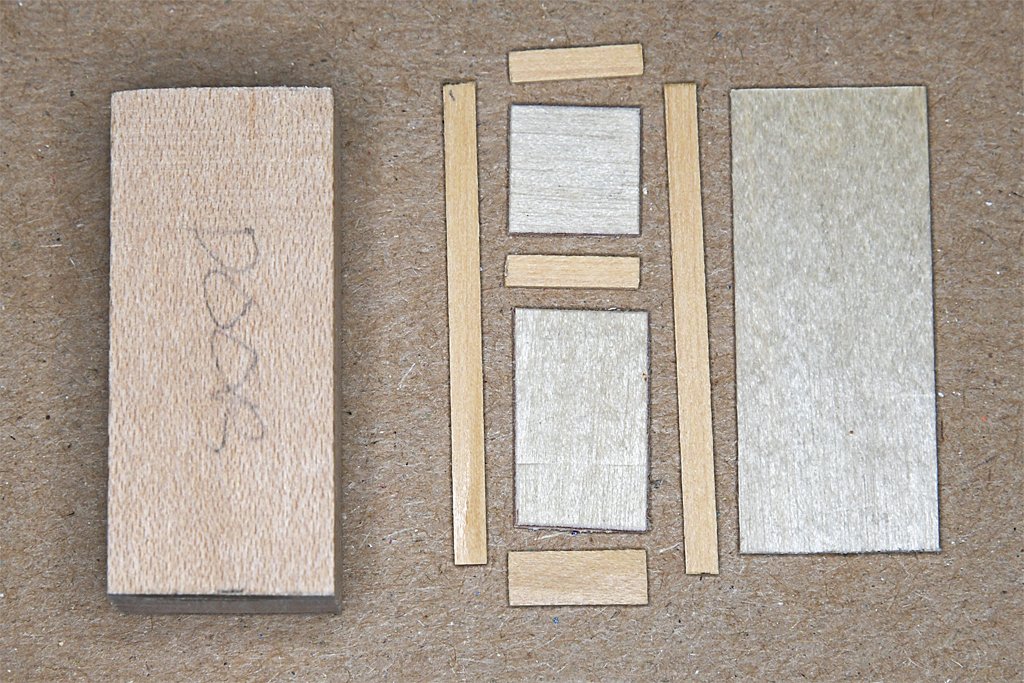
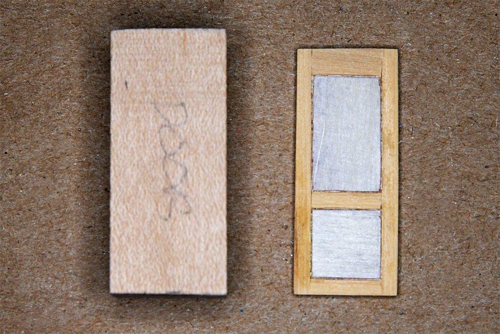
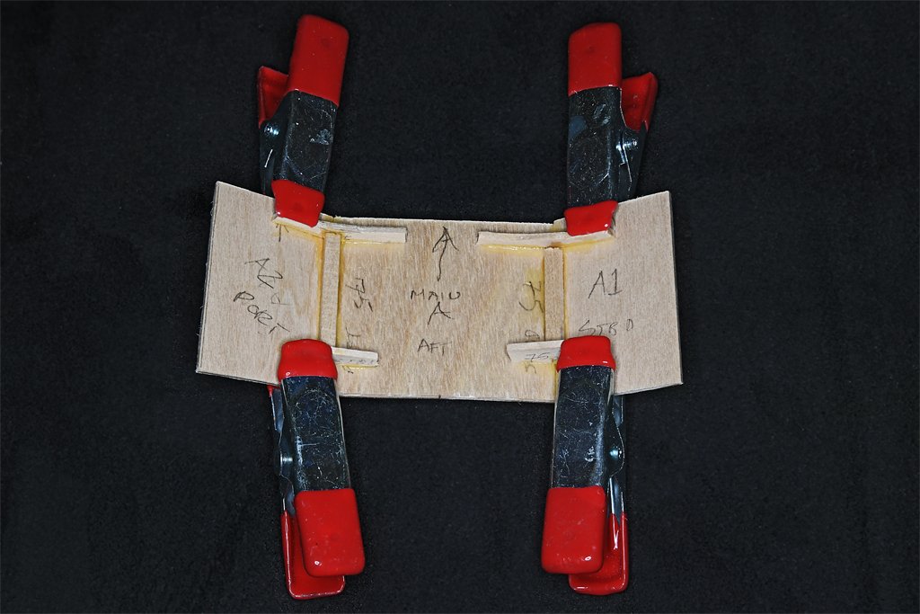
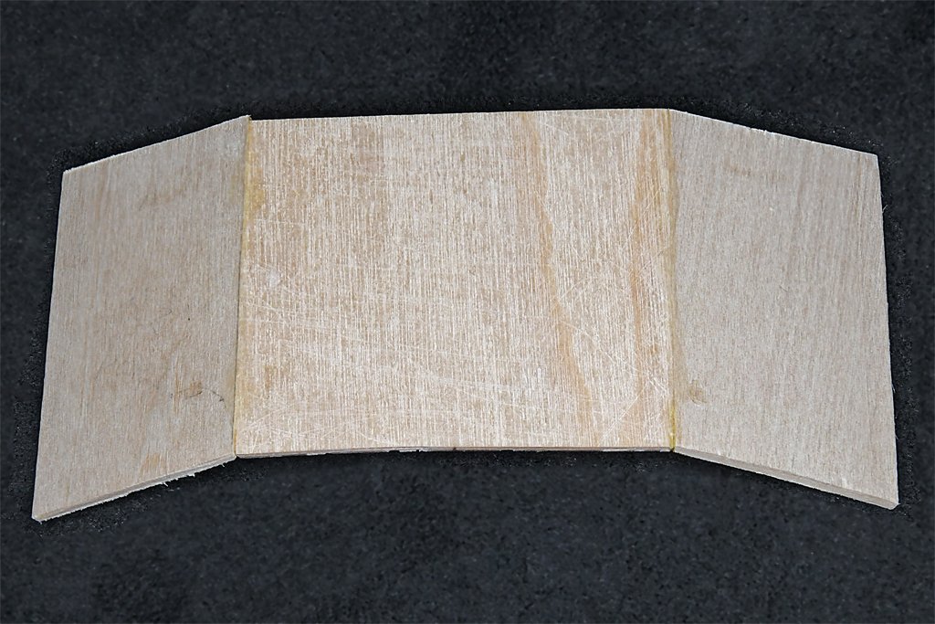
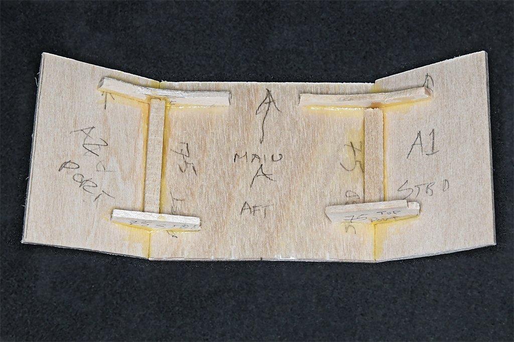
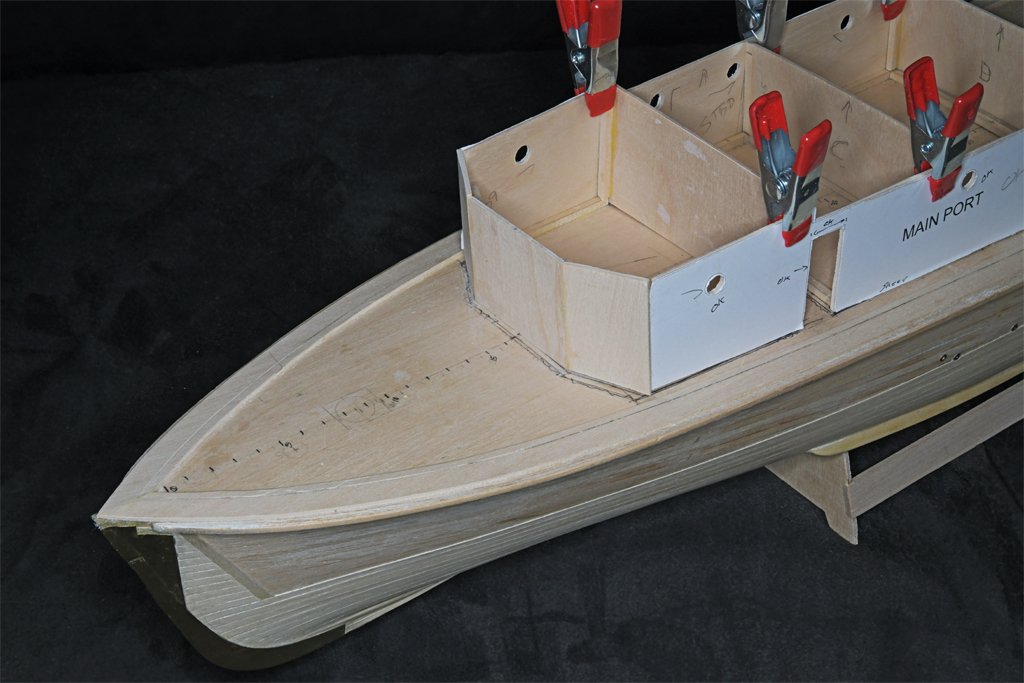
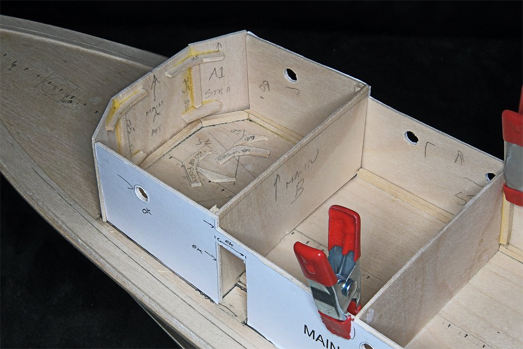
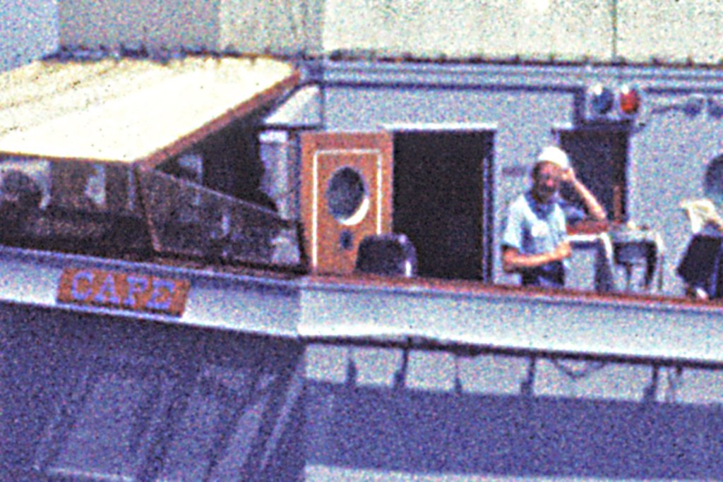
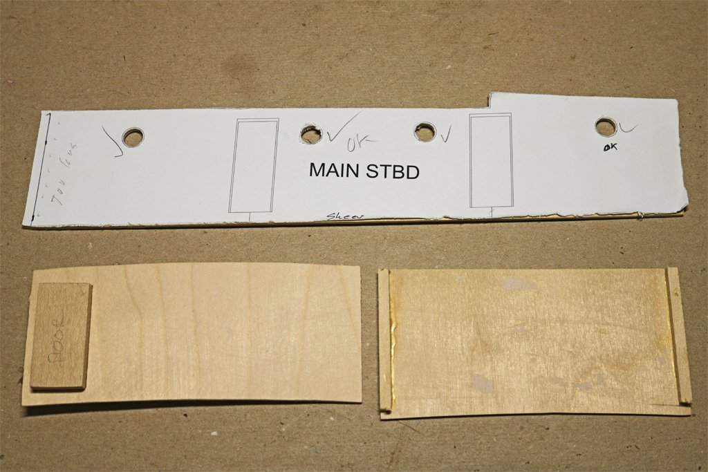
Thanks to everyone for the comments and likes! I have a bit more progress to report. The forward bulkhead of the deck house is the key to the entire assembly. The three pieces join at 150 degree angles so they must be beveled 75 degrees on the sides where they join. In addition, they have to conform to the camber of the deck, they are vertical relative to the water line, and the deck has a significant sheer. There are no "square" corners or 90 degree angles, so there is plenty of opportunity to screw up! I worried about this a lot, trying to figure out the shape of the two side pieces. I modeled it in 2D CAD, based on the deck camber. But the first two side pieces didn't come close to fitting! Then I did it in 3D CAD, taking into account the angles of the parts, and came up with what you see here. These pieces have to be assembled first. Then the rest of the deckhouse will be added to them - again at some odd angles. The house sides join the outer two front pieces at 120 degree angles, so the parts must be beveled 60 degrees on the joining edges. I used interior support pieces angled at 150 degrees to glue the pieces together. Then additional 1/8 x 1/8 inch (3.2 x 3.2 mm) pieces were glued to the inside of the joints for additional strength. I guess I did get it right because the pieces seem to come together correctly. At this point the outer front pieces are oversized and will have to be trimmed back and beveled appropriately. Only the front three pieces are glued together. Everything else is just clamped in place. There is a lot more work to do on the house sides before they can be glued to the front and interior bulkheads. There are seven "weathertight" doors (not watertight) on the exterior of the superstructure, Three at the main deck level and four on the O1 level. The doors were made like the doors in houses in the 1950s. They had two center panels that had "V" shaped grooves all around. I want to try to replicate this. Here is a "door kit." The side and top parts are 3/32 x 1/32 inch (2.4 x 0.8 mm) boxwood, the bottom piece is 5/32 x 1/32 (4 x 0.8 mm) boxwood, and the center panels are 1/32 inch plywood. The 1/32 inch plywood panel at the right is the finished door size. The other parts are glued to it to create a 1/16 inch (1.6 mm) thick door, as shown on the right. The block at the left is the template for cutting the door openings. The doors are a bit smaller, and will have 1/32 inch frames all around. There is a problem here. In my rush to assemble the door I put the wider 5/32 inch bottom part at the top! Well, it is a prototype, and Murphy had a hand assembling it. Reminds me of the topsail schooner build where I go in a hurry and switched the pintles and gudgeons for the rudder! How embarrassing! The doors were all painted gray on the outside. But inside they were varnished mahogany. The two doors to the pilot house will be open, as shown in this rather grainy photo. The grooves around the center panels were painted white. I want to replicate this in the model. The windows and window frames were also mahogany, as were the frames for the windshield, railings around the bridge and on the bulwarks, and a lot of the interior of the pilot house. I will be experimenting with pear wood to try to get the nice red mahogany color. But if that fails I will just paint the doors with "mahogany" paint. Here are pieces of the boxwood and plywood used in the prototype that have been stained with Minwax premium oil penetrating stain. This is "Red Mahogany 225." Looks more like brown mud! I have tried to use this stuff before and this is the best results I have had. Blotchy and streaked. Awful! This is why I said I may just paint the wood.
- 492 replies
-
- 11
-
-
-
- minesweeper
- Cape
- (and 1 more)
-
Keith, Search the US Patents for coal auto feeders or something like that. If there was a patent (and there probably are many) it will have drawings and an explanation how it works. Never underestimate what you may find in the patents!
- 457 replies
-
- 6
-

-
-
- sternwheeler
- Hard Coal Navy
- (and 1 more)
-
Thanks for the suggestions and offers. I'll try using the cherry and boxwood I have. If that doesn't work I may take you up on your offers.
-
I have basswood, boxwood and cherry. I have had horrible results trying to stain basswood, so that is out. It would be nice if I could stain boxwood. It carves nicely, and the doors have some detailing grooves like something you would see on indoor doors in a nice house. I might also order cherry if I don't have enough for the two or three doors I want to be open. On the inside of the doors the mahogany was varnished and the grooves were painted white. It would be a nice detail on the open doors. Because of these grooves, and the fact that I don't have a milling machine, I may build up each door from seven pieces with beveled edges where appropriate. The doors are small (1.3" x 058", or 33 mm x 1.47 mm), but large enough that I should be able to make them.
-
18′ Cutter for Syren — Clinker or Carvel Built?
Dr PR replied to glennb17's topic in Wood ship model kits
I built the Vanguard 18 foot cutter kit carvel style because I was using it with a vessel built around 1812. W. E. Mays "The Boats of Men-of-War" discusses the clinker vs carvel built cutters. -
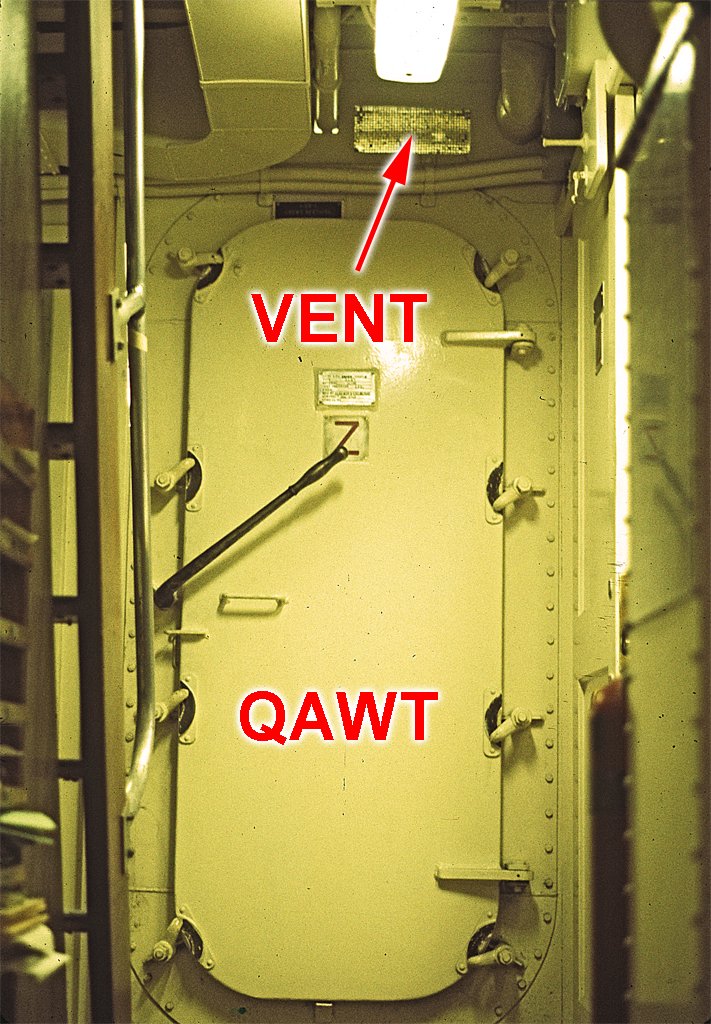
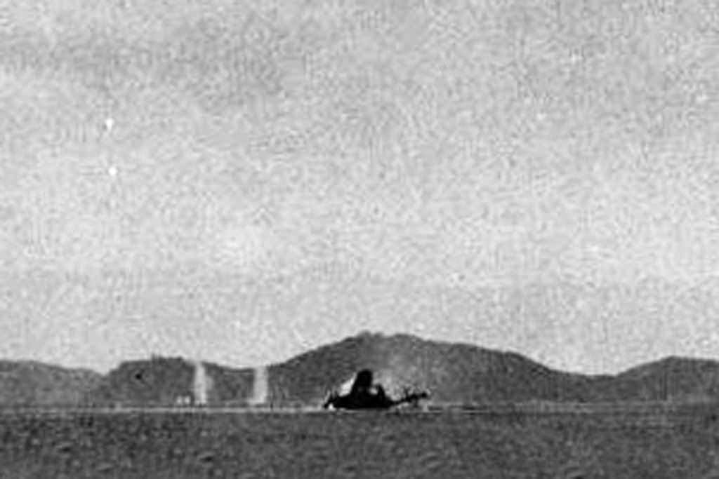
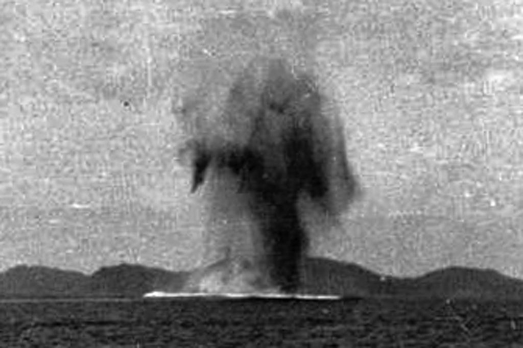
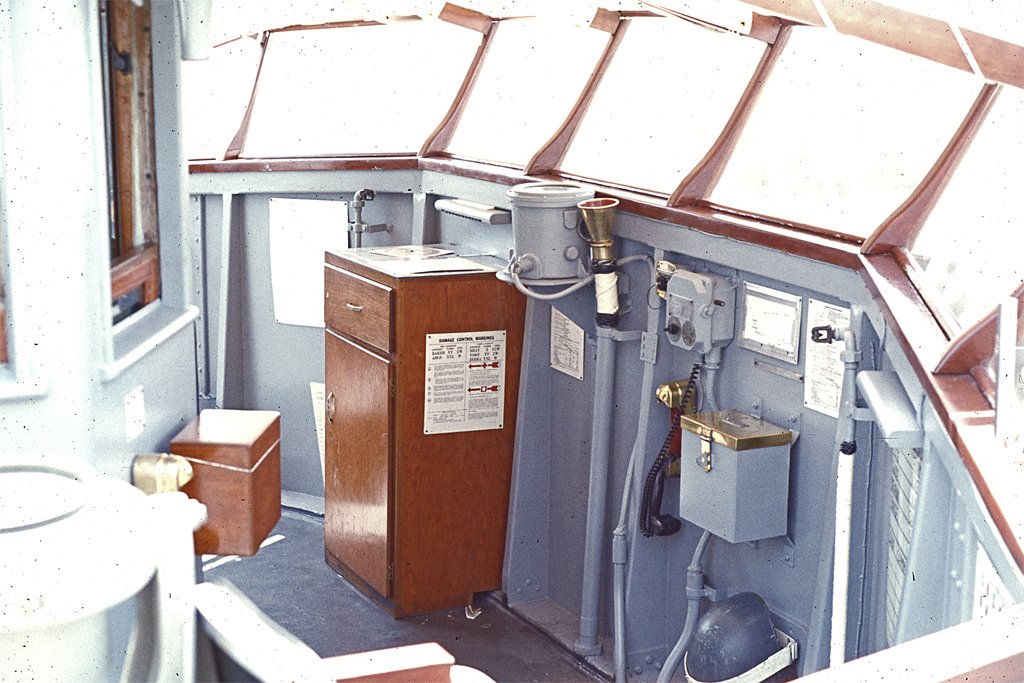
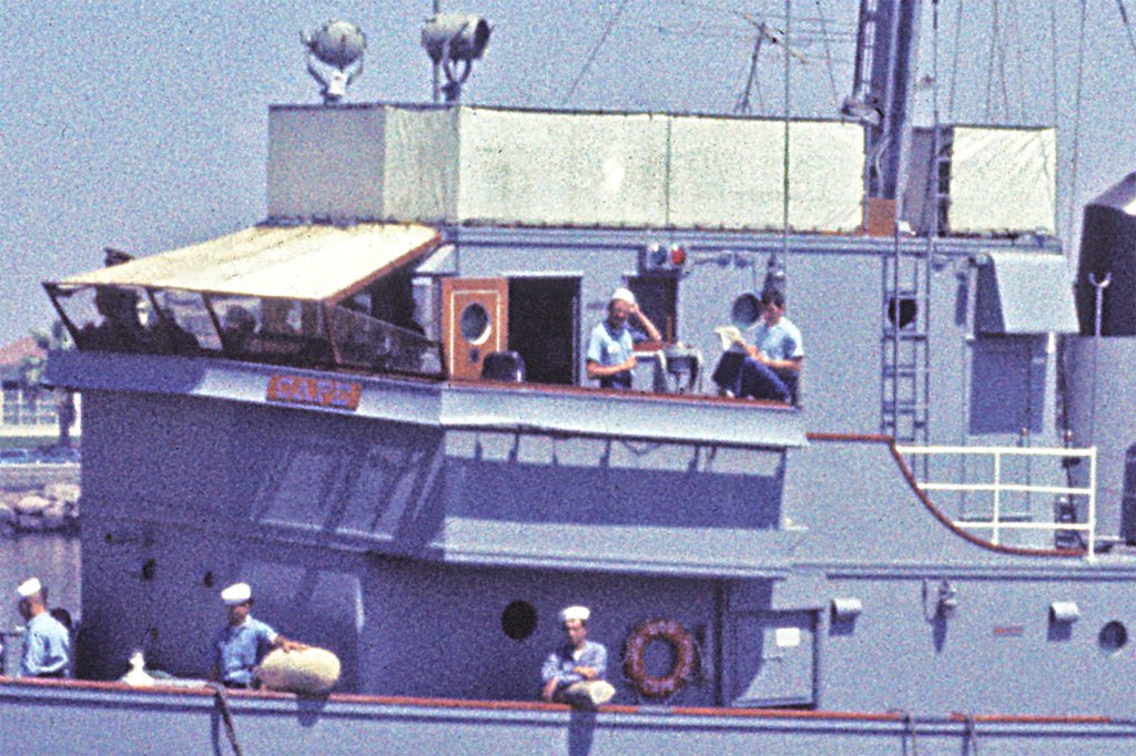
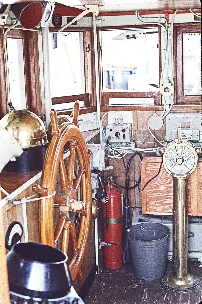
I have made a little progress on the physical model. Most of my time has been spent on planning the build sequence. The deck planking will go down first before the deck house and deck furniture is placed. But I wanted to get the main deck deckhouse pieces glued together before proceeding with the deck planks. That way I can be working on the superstructure off the hull while I am waiting for the planking glue to set. The front pieces of the superstructure fit together at angles so I had to bevel the edges. The sides also come together with the front pieces at an angle. Setting up the disk sander to the proper angles took some trial and experiment. I also need to cut openings for doors and air ports in the pieces before they are assembled. I made a wooden block "template" for cutting the door openings. This will ensure that all the door openings are the same size. I am also gluing some of the 1/8 inch (3.1 mm) square framing strips in the corners where pieces come together.. After the holes are cut and the pieces are trimmed to fit I remove the paper pattern and scrape/sand any remaining glue to prepare the surfaces for painting. I am planning to make the 12" air ports with some brass tubing with 1/4 inch (6.35 mm) inside diameter. I want to make the window with 1/4 inch acrylic rod. The outer surface will be polished and the inner surface will be painted with the ubiquitous Navy interior (puke) green. Like the mahogany trim on doors, windows and railings, I will need only a small bit of acrylic rod (~1.5 inch/38 mm). But the smallest piece I have found so far is a 6 foot (2 meter) 1/4 inch rod from McMaster-Carr. It costs only about US$2.50, but the shipping costs will be much more! I will continue looking around. Maybe a machinist friend will have a scrap piece. **** Work on the deckhouse brought back some memories from the Cape. The ship had one Quick-Acting Water Tight (QAWT) door. It was inside the superstructure on the main deck at the forward end of the mess deck. It opened into a companionway and ladder that led down to the crew's berthing compartment in the bow. It was called "quick-acting" because all eight of the "dogs" that clamped the door tight against the water tight seal were operated with a single lever, and not individually as on ordinary water tight doors. I thought this was peculiar for two reasons. First, all the other doors on the ship, including exterior doors, were wooden and non-watertight. For this door to serve a watertight function the main deck would have to be flooded, and that would only happen if the ship was on the way to the bottom. The other odd thing was that QAWT doors were installed in watertight bulkheads to prevent water from flowing from one part of the ship to another. But there was a screen vent over the door in this "watertight" bulkhead. It reminded me of the joke about something being as useful as a screen door on a submarine. For me this door symbolized the Cape. It was almost useless. I say almost, because if the ship was sinking it might delay the flow of water into the crew's berthing compartment below deck, and that might give the men time to escape through a scuttle on the main deck at the bow. Now stop and think - what are the likely causes for a minesweeper to sink? It could be attacked from the air or another ship, but the Cape was so small that just about any bomb or moderately large caliber projectile would blow it to pieces. Small cannon fire could blow enough holes to sink it, so in this case the door might serve a purpose. But given the primary role of minesweepers - to go into minefields and try to destroy them before they destroyed you - the most probable cause for sinking was detonating a mine. The picture on the left is the 184 foot long minesweeper USS Pirate AM-275 striking a mine. The photo on the right is what's left of the stern of the ship capsizing and sinking. These are grainy photos, but some of the little black dots in the air might be water tight doors. We had these photos posted on the Cape's bulletin board as a reminder of just how crazy it was for us to be anywhere close to a mine! **** The mess decks on the Cape were Damage Control Central (DCC) where damage assessment and repair coordination were carried out in combat. Perhaps the QAWT door was there in DCC to give the crew some hope of surviving and reason for attempting damage control. Being the Damage Control Officer for the ship, DCC was my station during General Quarters and when we were conducting damage control training. The Navy scheduled periodic training sessions where expert personnel from Damage Control Schools would come aboard and instruct us in damage control procedures on our own ship. Then we would run exercises and be graded for our proficiency. If we failed we had to do it all over again. During one of these training sessions we were being instructed by an older Damage Control (DC) Chief. While we were waiting for some "evolution" to begin I pointed out the screen vent in the watertight bulkhead to the Chief. He looked at it, then at me, and said nothing. Then I also commented about the sound-powered phone jack box in the mess decks that was about four feet above the main deck. It had a water tight cover over the jack, and I commented it wouldn't be much use if the mess decks were four feet under water. Again the Chief looked at me and said nothing. But I did say the watertight cover would keep the sound powered phone system from shorting out if we were fighting a fire on the mess decks with salt water from fire hoses. To this the Chief replied, in an assertive tone suitable for an instructor teaching a pupil, that sound powered phones didn't use electricity and couldn't be shorted out. "Chief, it isn't water flowing in those wires!" I replied. My leading engineman immediately pulled me aside and said "Mr. Hays, you don't talk to inspectors like that!" We passed the training anyway. But we were being trained by a Chief who had been in the Navy 20-30 years and had absolutely no understanding of how a principle communication system on ships worked! **** Damage Control Schools were some of the most interesting times while I was in the Navy. At Officer Candidate School in Newport, Rhode Island, we had engine room firefighting school. We climbed up a ladder on the outside of a three story tall steel structure with a mock-up engine room inside. It was 30 degrees Fahrenheit (-1 Celsius) outside and icicles were hanging from leaky fire hose connections. Inside the metal box at ground level was a 6-9 foot (2-3 meters) wide open tank containing burning fuel oil. When we opened the door to enter the "engine room" a thick cloud of oily black smoke poured out. We had to go inside without any breathing apparatus, walk along narrow catwalks and climb down two levels on vertical ladders while dragging a stiff charged 3 inch (75 mm) fire hose. The space was not lighted so we couldn't see anything, and none of us had been in this thing before! We felt our way along and when we got lower in the engine room we began to see the glow of the fire through the smoke. This was where we started to learn that the Damage Control School guys really knew a thing or two. A DC Chief was leading us and told the lead man on the hose (the nozzle man) to lean out over the blazing oil and hose it down with water! Right! We were going to put out burning oil with water!? But if you are an Officer Candidate Under Instruction (OCUI), a rating lower than Seaman and only slightly above scum - when a Chief says to spray water on burning oil you do it. The OCUI nozzle man bent the hose up in an inverted "U" over his head as we had been instructed, with the nozzle pointing down, and leaned out over the blazing tank. He rocked the "U" back and forth, spraying high velocity water fog over the surface of the oil and the fire went out! Wow! It really worked! The heat from the fire vaporized the water into steam. Steam is heavier than air and formed a layer over the oil that smothered the fire. And the water absorbed a huge amount of heat as it vaporized, and cooled the oil. We were all coated with gooey oil soot when we got back outside. I coughed up black spit for a week! After reporting to the guided missile cruiser USS Oklahoma City I was ordered to fly back from Danang, Vietnam, to Flight Deck Firefighting School in San Diego, California (missiles were built like airplanes and posed many of the same hazards). There we learned to do a few more impossible things. Magnesium burns hot enough to break down water molecules and combine with the oxygen, leaving hydrogen gas to intensify the fire. So when the DC Chief said he was going to put out a burning magnesium airplane wheel with water I was skeptical. And when they said they would put out a burning magnesium flare with water I was even more skeptical. But as we watched the School's DC personnel sprayed enough water on a flaming 3 foot (1 meter) diameter magnesium wheel to cool it to below ignition temperature. And the flare? They just crammed a fire hose into the end of the tube and the steam carried away enough heat to cool the fire and put it out! I wouldn't have believed it if I hadn't seen it with my own eyes! But the main event was rescuing a pilot from a burning airplane. The mockup plane sat at the center of a large (100 feet or 30 meter) wide pan. Below the plane was a pipe that had jet fuel bubbling up and pooling under the plane. Then they lighted the fire, creating a column of flame 20-30 feet (7-10 meters) around the plane. We had two hose teams dressed in ordinary work uniforms. A Chief led us to the downwind side of the blaze so the flames blew right at us! One hose team sprayed high velocity water fog toward the airplane to fight the fire. The second team had a long nozzle extension with a "spud tip" on the end. They followed close behind and held the spud tip above and in front of the first hose team to spray a sheet of low velocity water fog. Then we marched in toward the plane and into the burning fuel! The low velocity fog created a wall of water that beat back and cooled the flames. We followed it into a tunnel of flame that was blowing above and beside us. When we got to the plane a fellow in an asbestos suit climbed up to the cockpit to "rescue" the pilot. Then we all backed out together, having walked through flaming hell! Kids, don't try this at home! The impossible is impossible only if you don't try. Sometimes I think my 3+ years in the Navy was worth it just to have those experiences. It makes "thrill rides" at amusement parks look pretty lame!
- 492 replies
-
- 11
-
-
-
- minesweeper
- Cape
- (and 1 more)
-
Thanks for the tips. I do have a small amount of pear I can experiment with that was left over from the laser cut sheets in the Vanguard 18 ft cutter kit. I'll look for the steamed Swiss pear, but I will need only a few pieces.
-
I am modeling a wooden minesweeper. Most of the ship was made of Douglas fir - timbers, planking, plywood, etc. However, it had a lot of mahogany trim. The doors, windows, door frames, window frames and quite a bit of other parts were made of mahogany. I only need a small amount of wood for the trim, and I can't cut my own scale lumber. So my question is what other more common woods would make a good substitute? Should I use a common wood and try to stain it to look like mahogany? Any suggestions will be appreciated!
-
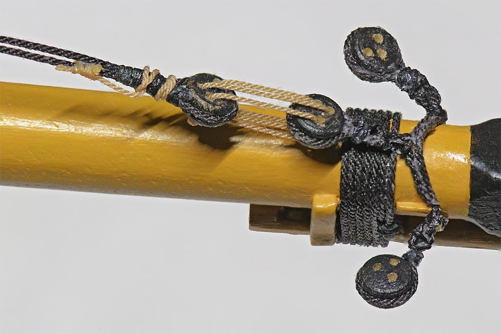
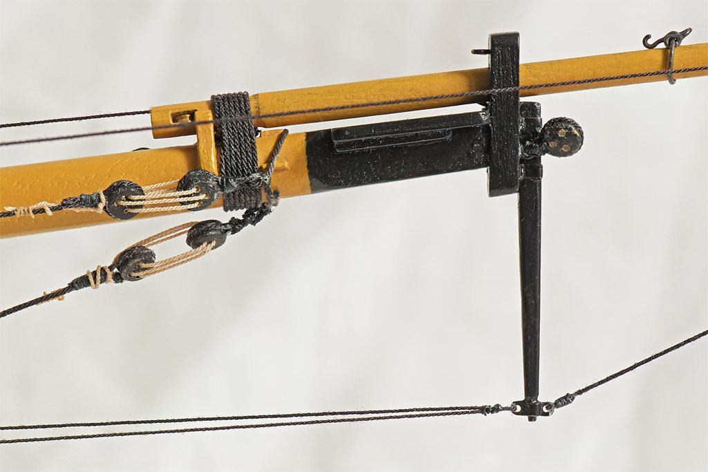
Red, You could have reduced the congestion at the bowsprit cap by combining several of the hearts/deadeyes on a single collar. Lever (page 21) shows two bobstays on a single collar. Marquardt (page 170) shows three on a collar for stays. Petersson (page 84) shows the bobstay and two jibboom guys on a single collar. So this technique was not uncommon. However, making these collars with multiple attachments can be tricky. Getting the hearts/deadeyes/thimbles positioned around the boom with the correct spacing takes a bit of practice. You can see in this picture of the bottom side of the bowsprit that I really didn't get the collar tight enough around the spar. The problem is that I tried to make the collar with a single turn of rope spliced together at the center deadeye. I should have created an open collar with eyes spliced in the ends - like you are doing. Then I could have drawn it tight to the boom with lacing. It works anyway but wants to pull over the side thumb cleats (the top one holds it in position). Live and learn!
- 436 replies
-
- 3
-
-
- Syren
- Model Shipways
- (and 1 more)
-
John, I'll let you know how much "fun" it was after it is done.
- 492 replies
-
- 7
-

-
-
- minesweeper
- Cape
- (and 1 more)
-
Mark and Gary, Thanks. I have a resin 3D printer, but I haven't used it in quite a while. A few years ago I experimented with a bunch of things for a 1:96 scale model of the USS Oklahoma City CLG-5 and got very nice results with details on very small pieces. But the resin is just too brittle and the small parts can't be handled. I may print some of the more complicated pieces that would be difficult to make by hand - like the winch motors and gear boxes. But I prefer to make things out of brass where possible. Some things like the deck gratings and wheels on the scuttles will be photo etch.
- 492 replies
-
- 4
-
-
- minesweeper
- Cape
- (and 1 more)
-
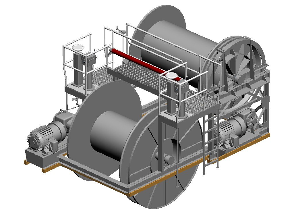
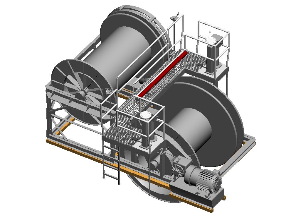
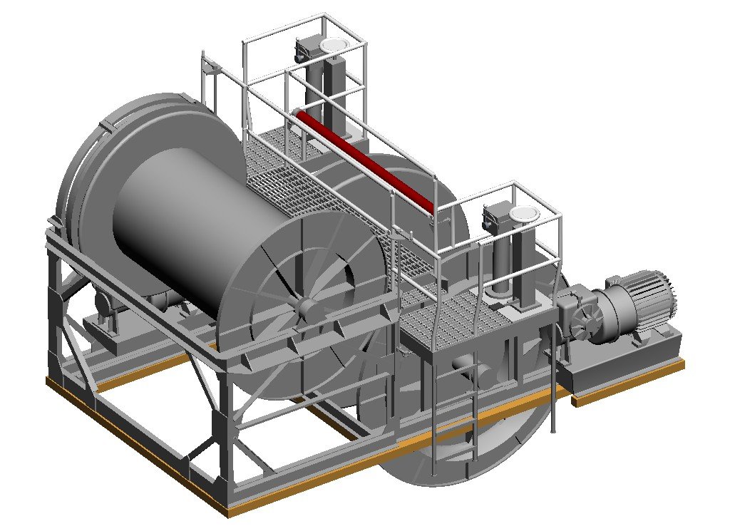
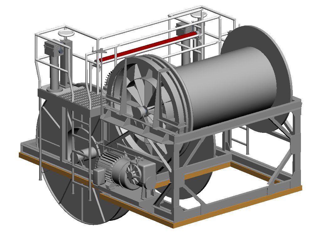
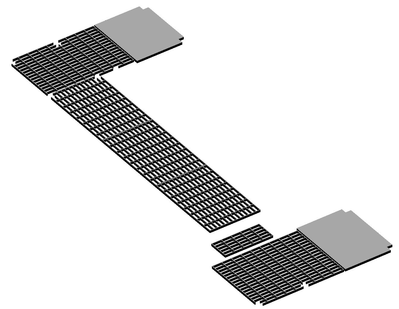
Two winches were combined in one framework. The upper winch was for the towing and power cable for the acoustic minesweeping device. The larger and lower winch was for the magtail - the magnetic minesweeping cables. They had similar controls and motors. The gearbox was the same for both winches but the motors were slightly different in size and power, but manufactured by the same company so they look alike. I think this will be the most complex assembly on the model. It will be 4.29 inches (109 mm) long (fore to aft), 3.375 inches (85.7 mm) wide and 2.33 inches (59.7 mm) high. This thing was difficult to model because the four blueprint drawings that show all or part of it give different dimensions! And the dimensions for most parts aren't shown, so it was necessary to measure and scale everything. Worse still, a lot of the framework pieces aren't shown (or are faint outlines) so there was a lot of guesswork and successive approximation until everything fit in pretty good agreement. There were some parts shown in the drawings that simply wouldn't work. For example, there was a cross brace for the framework that would pass through the sides of the cable reels! I have been working on this drawing for 12 days trying to sort out these things. It may not be perfect (there are some parts of the mechanism I won't try to model) but it will be good enough for this model. These 3D CAD drawings serve two purposes. First, they force me to try to understand how the things were built, and determine some reasonable dimensions. But the other purpose is to find parts that should be made by photo etch. I am preparing drawings to send to a photo etch manufacturer (I don't want to mess with doing it myself - that can be pretty frustrating). This is an example of some photo etch pieces from this winch assembly - the deck gratings. I can probably 3D print them - I have done some very small screens and such. But the 3D print material is brittle and these will be thin (0.020 inch or 0.5 mm) and very fragile. They will be more likely to survive handling if they are photoetched brass or stainless steel. I may use 3D printing for the motors and gearboxes. Although the motors were slightly different sizes (about 3% difference) I will probably make them all the same size. Most of the framework will be made of brass pieces soldered together.
- 492 replies
-
- 10
-
-
-
- minesweeper
- Cape
- (and 1 more)
-
Steve, I think you may have a problem here. You seem to be worrying about it too much! Your work looks really good!
-
Anchor windlass
Dr PR replied to bushman32's topic in Discussion for a Ship's Deck Furniture, Guns, boats and other Fittings
You might find a patent for the windlass used on oilers in the US Patent Office archives. The patent will have lots of drawings showing every part. However, there are probably many windlass patents. It would help if you knew the manufacturer. That would narrow the search. And you can ignore patents before the date the ship was built. -
Steve, When in doubt go with Lever. He wrote the book in the period that the Prince was sailing, so it is a good source. Unfortunately, he doesn't say much about fore-and-aft rigs. Lennarth Petersson's "Rigging Period Fore-and Aft Craft" has a good section on topsail schooner rigging a lot like the Prince. Unlike most books he does show where the lines were belayed. I also found the instructions on the Internet for several topsail schooner kits. The full plans are not available, but the instructions often show how to rig the bowsprit, yards and other things.
-
I had problems with planks swelling and shrinking on my first two plank on bulkhead models, causing cracks to open up. Since then I have coated the inside of the hull planking with thin epoxy. It flows into the cracks between planks, and between the planks and bulkheads, sealing the hull. After the epoxy cures the hulls are really solid. After 35-40 years the first hull I built this way still has no cracks between planks. I plank the hull and seal it before installing the deck.
-
The jib boom inhauls and outhauls were rigged only when needed. I put the necessary hardware (eye bolts and sheaves) in place but left off the rigging. Serving is just a matter of choice for a model. I think most people do not add it on smaller scale models. If you are anal retentive I suppose you must do it. However, if you are making this build to learn about rigging details, adding the serving will educate you! The gammoning for the jib boom is called a crupper. That's a bit of trivia I'll bet you didn't know! I guess it sort of serves the same purpose as the crupper on a saddle. Rigging is complicated and takes a lot of planning. Even so you will occasionally find two lines crossed and chafing and need to reroute one or both. But the really trying part is when you have a moment's distraction and you bump something with your hand or catch a shirt sleeve on a spar and break something. Two steps forward and one step back. Plan on it! If you rig the model without sails it will be a relatively simple (but slow) task. Add the sails and the work doubles or triples. If you are in doubt about how to rig a line ask. There are many folks here who are happy to help.
-
But does it really work better than plain water? It is very easy to get gentle bends across the narrowest dimension like you show with water and heat. The real test would be to compare bending planks across the width with water and vinegar. This has always been the biggest problem for me, even with adequate heat.
-
Gary, That True Metal Iron "paint" really looks like steel! And your "weathering" technique simulates the slight color differences seen in large steel sheets. Very nice. For other readers Gary does mention my MSI build. The MSI blueprints show the sacrificial oak sheathing but do not say much about how it was applied to the hull. I had never seen this sacrificial sheathing and was at a loss how to proceed until Gary explained that it was common on fishing boats and showed how he was doing it. This is an example of how important this Forum is for sharing information. Thanks, Gary!
-
What are the lines you have coming down to cleats on both sides of the boom and then forward to blocks? The standing parts of the tackles are attached to a ring bolt on deck, pass between the bitts to the blocks, with the running parts belayed to pins on the mast ring. If the boom is swung outboard the tackles will foul the bitts. It was common for the standing parts of tackles on lines from the boom to belay to ring bolts under the boom jaws, and the running parts to cleats on the boom. This way the lines move with the boom and do not foul anything.
-
Kirby, You said planking was a slow process. Are you in a hurry? For what it is worth my last two completed models took about 15 years each, and I have one on hold that was started in 2004. If and when I finish a workshop I will resume that build. Who knows how long it will take to finish the MSI build? But I am not in a hurry (obviously) because these models give me something to do when everything else that is going on around me becomes too hectic. Sometimes slow is good! “Maybe I'm lucky to be going so slowly, because I may be going in the wrong direction” ― Ashleigh Brilliant
- 139 replies
-
- 1
-
-
- Lady Nelson
- Amati
- (and 2 more)
-
SS, You have an interesting background! It fits the polymath description. Your mention of Mariner 9 photos caught my attention. I have several in-laws that work at JPL. About 30 years ago my brother-in-law was showing me through their library. It had shelf after shelf of ring binders with photos from various space missions. I remember opening up a volume of Ranger pictures, each one closer and closer to the surface of the moon. The last was taken just a few yards before it crashed into the surface. He commented that I was possibly the only person who had viewed those images after that mission was over. They were busy trying to copy the digital images from magnetic tape to DVDs before the data was lost. I hope you develop a keen interest in ship modelling. It will be interesting to see what projects you choose.