Dr PR
-
Posts
2,471 -
Joined
-
Last visited
Content Type
Profiles
Forums
Gallery
Events
Everything posted by Dr PR
-
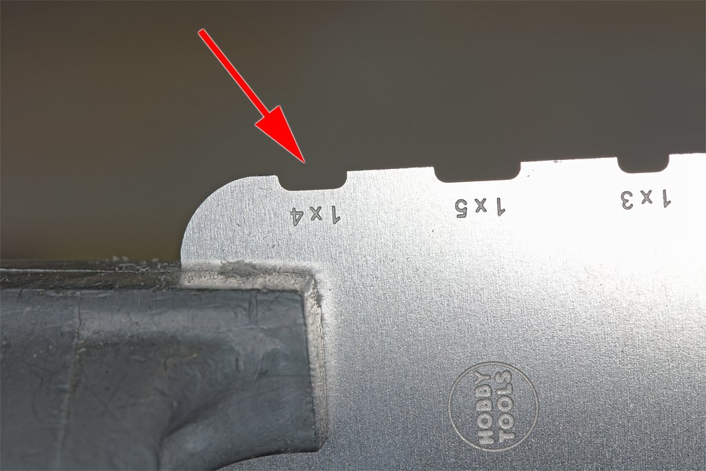
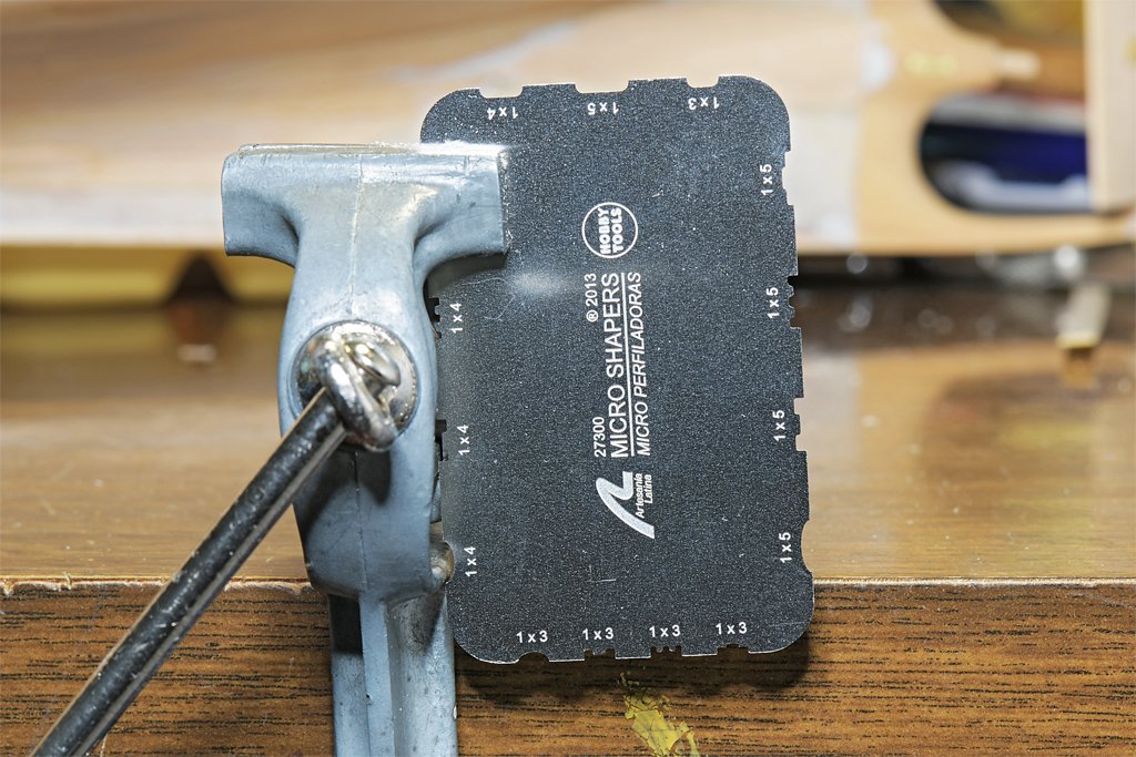
 So how am I supposed to create this sheathing with the scale 0.005 inch (0.13 mm) gaps between the planks? I quickly abandoned the idea of using 0.005 inch thick brass shims to space the planks. Instead I decided to bevel the edges of the planks and jam them together, leaving a visible gap at the top surface. A couple of years ago I was looking through build logs on the forum and was envious of some of the models that had elaborate moldings instead of plain rectangular trim. I knew that this effect was achieved with draw plates with a variety of cutouts, so I bought four Artesania Latina draw plates for future use. Well, the future is here, and I used the 1x4 mm cutout to round the edges of the 3.9 mm wide sheathing planks. This worked petty good. The "corduroy" effect is very subtle, but with the proper lighting angle it is noticeable. I have finished the port bow and the port aft sections above the water line. The very thin basswood planks bend and twist to shape without the need to use heat, and the glue is good enough to hold them in place without clamps. But I did use blue masking tape to hold the planks in place until the glue (Sig-Bond Cement) set. I need to be sure to remove excess cement between the planks after they are positioned. It fills in the gaps and is hard to remove after it has hardened. I use the tip of an old #11 blade drawn backward (top or flat edge first) through the gap to scrape out any glue that flows there. Austin Cox (the current Cape owner) has confirmed that the sheathing planks that remain at the bow of the ship today were not tapered. They are the original 7 1/4 inch wide planks, and he has replaced at least one of the original parts. So I will complete the sheathing planking below the water line without tapering the planks. Fitting and trimming the pieces to the bilge keels, garboard strakes and keel should be interesting! It definitely will be contrary to the traditional modelling dogma of tapering the planks precisely to meet that preconceived "ideal."
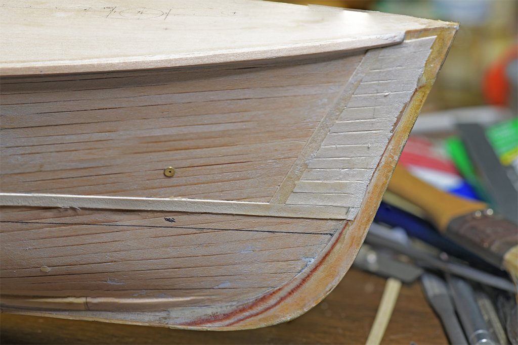
- 492 replies
-
- 8
-

-
- minesweeper
- Cape
- (and 1 more)
-
Vaddoc, That is a very good question! The blueprints don't say anything about the function of these "sheathing" planks. However, I can make an educated guess. The sheathing extends above the waterline in places where heavy objects (anchor, minesweeping floats, acoustic minesweeping device, etc.) are hoisted over the side. So it seems to be there for protection of the hull planking. Minesweepers often operated in shallow waters (especially an "inshore minesweeper" or MSI) where they might run aground. The entire hull surface below the waterline is covered by the sheathing. I guess the sheathing below the waterline is there to protect the hull planking. The sheathing itself provides no water tight integrity given that the planks were placed with 1/4 inch (5 mm) gaps between the planks. The blueprints specifically say that nothing is to be placed in the gap. But the sheathing was installed over a waterproofed cloth covering on the hull planking. That would provide some protection for the hull planks. Maybe the sheathing was there to hold the water tight cloth covering in place? I know the larger ocean going minesweepers (MSO) had similar sheathing along the sides where heavy objects were handled - I have a photo showing this. So this seems to be a common feature of wooden minesweepers after WWII. But on the MSOs the sheathing planks were placed vertically - with gaps between them - instead of horizontally like the MSIs. The MSIs were built in shipyards that specialized in wooden fishing boats. I wonder if they had the same type of sheathing? So far I have found no answer to that question. **** Scale (1:48) planks are VERY thin - 0.015 inch (0.4 mm). They curve and twist to fit the hull curvature with little effort. Just the glue holds them in place without any clamps. But I have been taping them down with blue painter's masking tape to give the glue a chance to set.
- 492 replies
-
- 5
-
-
- minesweeper
- Cape
- (and 1 more)
-
Best White Wood Glue For Ship Building
Dr PR replied to OldeManToad's topic in Modeling tools and Workshop Equipment
I have been building wooden models for at least 70 years, and have used a lot of different glues. Way back then I used Testor's wood glue. I don't know if it is still made, but Duco Cement is the equivalent. It is nitrocellulose dissolved in acetone. It is one of my primary wood glues because it sets in 20-30 seconds, giving time to reposition parts. It makes a good bond, leaves a shiny film, and can be loosened with acetone. I used it for most of the Albatross topsail schooner build - that hull is about 40 years old now. My local hobby shop (killed by the pandemic and on-line sales) specialized in radio controlled airplanes, but also carried a selection of wooden ship model kits. The wood glue of choice there was Sig-Bond aliphatic resin used by model airplane folks. It is a very good white wood glue that leaves very little (if any) visible film. It can be loosened and washed up with water. Heat also liquifies the dried glue, and it resets when it cools (maybe not as strong as the original bond). It is what I am using on the MSI build. I recently used Titebond Original for the Vanguard 18 foot cutter model. This is what Vanguard recommended, and many on this forum recommend it. It is pale yellow and leaves a slight film. It can be loosened with heat as Gregg said, but I found that it will also loosen with water. If you loosen it with heat it will reset again with a good bond when it cools. I use Elmer's Glue-All white glue in places where I do not want any visible dry glue. Office Works school glue seems to be the same. They clean up with water. These are not as "strong" as the other glues mentioned above. I use these glues diluted 1:1 with water to fix rigging knots with threads like cotton and silk that soak up the glue. Shellac can be used to fix knots in ropes and to shape the curves in ropes. It dries very quickly and is soluble in alcohol. It is also used as a wood finish. NOTE: None of the glues listed above will adhere to polyester rope! They do not soak into the polyester thread and just form a weak coating that will come loose with a bit of pulling. Duco Cement does dry to a hard coating that is stronger than the other glues. I have used Locktite CA gel (cyanoacrylate or "super glue") when I need a very quick setting glue in small spots. It usually sets in 5-10 seconds, but the latest use took 30-40 seconds. I don't like super glue - the vapors irritate my eyes. High heat will weaken or loosen CA. It leaves a white residue when it hardens. None of the glues listed above are good for wood to metal or metal to metal. If you want to glue wood to non-porous materials like metal or plastic the only good adhesive that I know of is two part epoxy. I am reminded of the slogan on inner tube repair kits from the 1920s and 30s. "If you don't want it on, don't put it on!" It will clean up with rubbing alcohol (isopropanol). Hardened epoxy can be filed and drilled, but is not as hard and strong as metal. You should brush/sand the metal/plastic surface to be glued to roughen it a bit so the glue can adhere properly. I use liquid two part epoxy "paint" to seal the inside of planked wooden hulls. It soaks into the wood, bonding planks edge to edge, and planks to bulkheads. It makes a rock solid hull that will not develop cracks between planks as the wood swells and shrinks with changing humidity. For the topsail schooner hull I used epoxy paint flying model airplane builders use to seal wood from fuel. On the MSI build I used the clear two part resin used to form clear "plastic" layers on counter tops. **** Although all of these glues will adhere to painted surfaces, the bond is only as strong as the paint bond to the wood/metal. Remove paint from surfaces that are to be glued. None of these glues will adhere well to greasy or oily surfaces (including finger print oils). Some won't adhere to wet surfaces. Clean and dry the surfaces before gluing. -
Mark, Your mast positions look good! It was common on ships of this period to make the transom (fashion piece) a bit wider than the hull, and with a rounded outer edge. Then a decorative piece was placed against the hull planking and the front side of the curved transom outside the hull planking. However many schooners of this period had very little decoration at the bow or stern. Chapelle's lines drawing in The Baltimore Clipper (page 83) shows this curved outer edge of the transom extending slightly beyond the hull planking (the drawing in your post #134 above).
-
Steve, The gaps will be 0.005" (0.127 mm)! I think I will just apply the planks pushed together carvel style and then run a scribe along the joint to create an apparent gap between the planks. I do have some 0.005 inch brass that I could use as shims, but I think that would just be asking for trouble. For what it is worth, the basswood scale planks I have are about 0.154 x 0.0155 inch (3.9 x 0.04 mm). That comes out to 7.39 x 0.744 inches at 1:1 scale. The original red oak sheathing planks were 7.25 x 0.75 inch. The scale planks are a little wide, but almost perfect thickness. And no, I do not intend to try to shave 0.0029 inches from each plank to get perfect scale! I do not have the tools to do that. Jim, The gaps are very apparent in the photos I took of the Cape back in the 1960s, so they should be seen on the model, at least if you look closely. Those parts of the hull appeared to be "corduroy" planking.
- 492 replies
-
- 5
-
-
- minesweeper
- Cape
- (and 1 more)
-
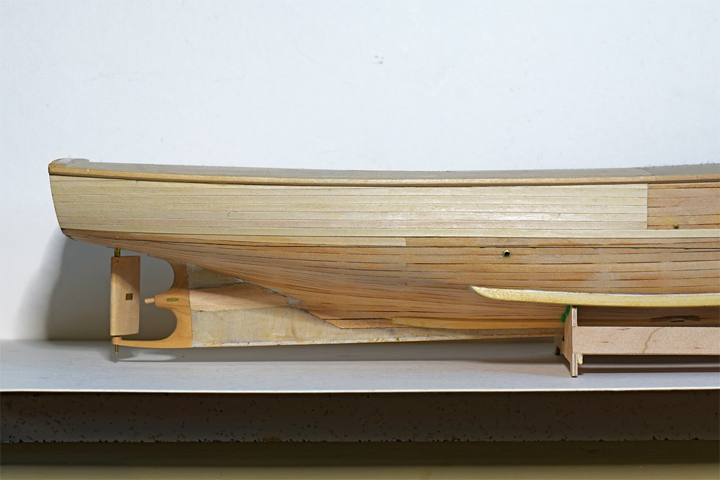
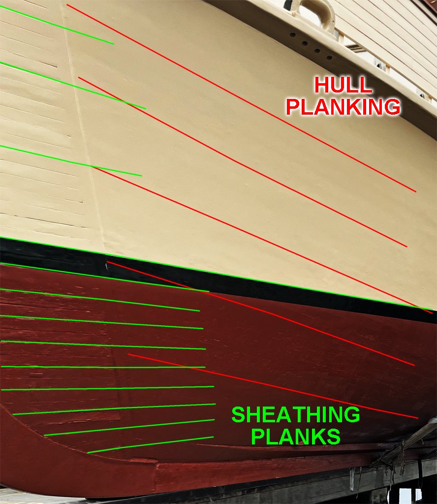
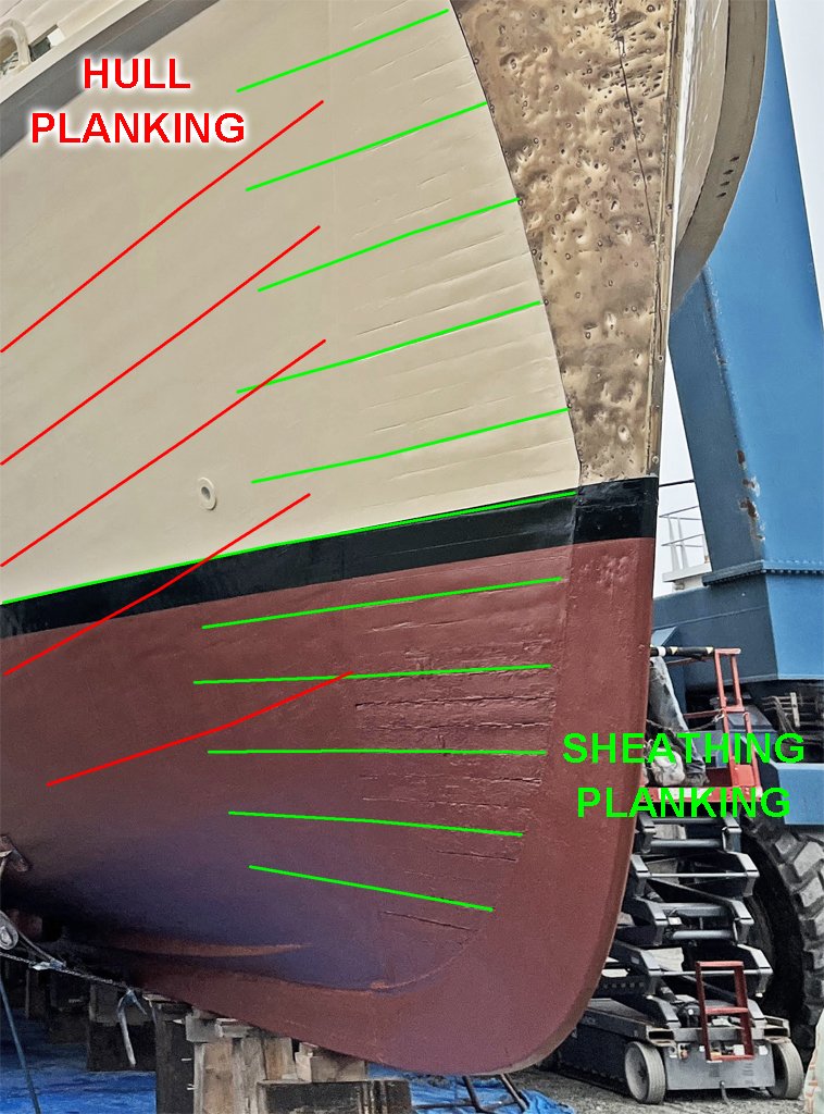
I'm back! I have been thinking about the third layer of sheathing on the MSI hull - and scratching my head to figure out how it was applied. I need some help here! The blueprints say the sheathing was applied from the 11 foot waterline down to the bottom of the keel, bow to stern. Coincidentally, the top of the boot topping is also at the 11 foot waterline. To make things more interesting, the 7 1/4" x 3/4" red oak planks were attached with a 1/4 inch gap between them, and the blueprints are clear that this gap must not be filled with anything. Nothing is said about tapering the planks. So how were the sheathing planks applied to the hull????? The current day Cape offers few clues. From the photos the owner Austin Cox sent it looks as if that outer layer of sheathing was removed at some time in the past. Only a small amount remains at the bow. Here are some photos he sent of the ship out of water. The red lines show the lay of the outer layer of the hull planking. These planks appear to be tapered, and about 2/3 as wide at the stern as amidships. The green lines show the lay of the remaining sheathing at the bow. You can still see the 1/4 inch gaps between planks, but they have been filled in a bit over the years. It is obvious that the sheathing planks run parallel to the top of the boot topping, as the original blueprints show. But look at the bottom of the sheathing - the planks appear to intersect the garboard strake and keel at an angle, and do not run parallel to them. So the question is whether or not the sheathing planks were tapered? From these photos it appears they were not, and were trimmed at the ends to fit where they met the garboard strake and keel. All opinions are welcome! One other thing you can see in the photos, and is shown in the blueprints. The metal stem band rides over the sheathing. Great! Now I need to rip it off the model, apply the sheathing, and put it back again over the sheathing!
- 492 replies
-
- 3
-
-
- minesweeper
- Cape
- (and 1 more)
-
Mark, It does look like the port lids hinge upward, and I see no evidence of another half hinging downward. That indicates a single piece lid. The question then is if you have room for hinges on the bulwark planking over the gun ports? Are the bulwarks high enough on your model to allow the gun barrels to extend freely through the gun port and not strike the top of the port or the underside of the port lids? The guns should be elevated a bit from the horizontal to extend the range (how much I do not know).
-
Mark, The gunport covers/doors/lids are one of the mistakes I made on this build. They are entirely wrong! I wanted port lids because of the low freeboard of the smaller ships. I really knew nothing of small schooner gun ports. I was familiar only with the single piece lid hinged at the top that was used on larger ships. At the time I built the hull (1980s) didn't have many references for such things and I was winging it. The bulwarks should have been another plank higher, but the kit plans didn't show that, nor was extra planking provided. I tried to make the kit gun carriages and oversized cannons work, but the barrels wouldn't fit under the cap rail (I should have thrown out the cannons). I made new lower carriages, but even then the gun barrels rubbed against the bottom of the cap rail. There was no space for gunport hinges on the bulwark planking so I "hid" them in the cap rail. Bad! I doubt this was ever done on a real vessel! Mondfeld's Historic Ship Models (page 177) illustrates a dozen gun port lid designs, and gives the date range when each was used (in Europe). He also shows the construction of the gun ports (pages 97 and 177). Now I think the two-part upper/lower split gun port lids would be more appropriate. There were several variations on smaller ships and schooners. 1. Gun ports did not have lids, but were just open to the sea. Sometimes the cap rail extended over them, and sometimes it was cut away over the gun port. 2. Where there is space on the bulwark planking for the hinges both the top and bottom halves can be hinged. The upper part requires a port lid lanyard to lift it, and on larger ports it might even have a small gun tackle. The lower lid would also have a lanyard to pull it back up. 3. The lower lid was hinged, and had the lanyard. The upper lid was "portable" - it just fit into place above the lower half and was installed/removed using handles on the inside of the lid. It was latched into place inside the gun port. The upper lid is sometimes shown as fitting against the bottom of the cap rail (no space for hinges). Sometimes only the lower half is shown in drawings. Marquardt (The Global Schooner) shows this in the plans for the British schooner Berbice (pages 40, 44). The lower lid has a cutout for the cannon barrel. The port lid appears to be hinged to swing downward. On page 45 he shows a drawing of an (unnamed) American schooner with these half port lids, and the American schooner Boxer on pages 61 and 62. Two more "unknown" American schooners are shown with the lower half port lids on pages 122 and 123. I don't know if these vessels used portable upper half port lids. 4. Both lids were portable, without hinges. 5. Some vessels had two part lids that hinged vertically, with the halves swinging back on either side of the gun port. I don't know if this was ever used on an American Baltimore clipper. Gun port lids were often pierced with square or round "ventilation scuttles." These were smaller openings than the gun barrel diameter. Sometimes the port lids had holes to allow the guns to be stowed in the run out (battery) position. This gave more open deck space than when the guns were stowed entirely inboard. The barrels were plugged to keep out water, nesting birds, etc. This also showed how heavily armed the ship actually was (as opposed to closed port lids and false painted "gun ports"). Two part lids fit fairly tightly around the barrels. **** There were variations from the ordinary square/rectangular gun port. Some ships had "D" shaped gun port openings in the bulwarks. Some vessels had gun ports with rounded lower edges (the curve of the "D" was on the bottom). Some had the curve of the "D" on top, usually with an arched cap rail over the top. I don't know if these ports had lids. Rectangular ports were more common. **** Chapelle writes a lot about the Lynx/Musquidobit but I haven't seen anything about the gun port lids. I wonder if the plans the British made after the ship was captured show details this small?
-
Mark, Because of the angle of the photo the actual angles would be a bit different if the photo had been taken parallel to the plane of the waterline. However, they would not be much different. 12.5 degrees for the fore mast and 14 degrees for the main mast is close to the average mast rakes for Baltimore clippers. These are good rake angles. Slight difference in rake angles are not critical - no one knows for certain what they were on the real ship. The transverse (port-starboard) angle is very important - it should be 90 degrees to the waterline, and it is imperative that both masts have the same angle - any difference is very noticeable. And both should be on the centerline of the deck, otherwise would look strange. On the Albatross I cut the mast hole in the deck level transverse beam very carefully and used round files to taper the fore and aft edges so the mast would have the desired rake angle. Then I made the lower sliding piece for the mast foot and with the mast at the desired rake angle carefully marked the center of the mast foot. After cutting the square socket for the mast foot I set the hull as level as I could get it. Then I put the mast in with the foot resting in the socket in the sliding piece. I moved the sliding piece back and forth (port/starboard) until the mast looked vertical. I did this several times using whatever tools I had at the time to measure the angle. I sweated bullets getting the main mast as true to vertical as I could. When I thought I had it in the right place I glued the sliding piece in place. Then I just set the fore mast to be in line with the main mast, vertical or not. Now I have a laser level (Bosch GLL50-20) that generates a bright red "+" marking horizontal and vertical. It would be easy to level up the hull and then project the laser beam down the centerline of the vessel. It would be trivial to get the masts vertical using this tool. And the laser level is perfect for marking horizontal water lines on curved hull surfaces. You can also use it for other jobs around the house (getting pictures hanging straight, adding on new rooms, ...). The GLL50-20 is about $60 on Amazon.
-
Thanks Steve!
-
Thanks John!
-
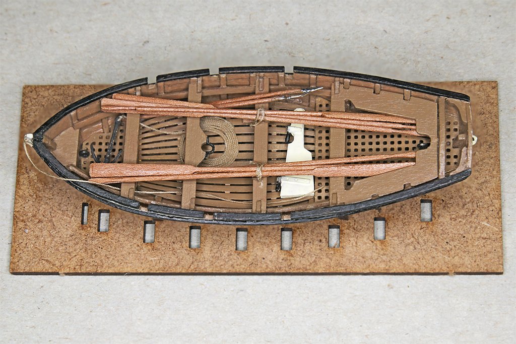
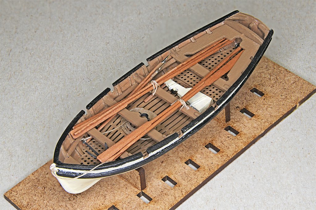
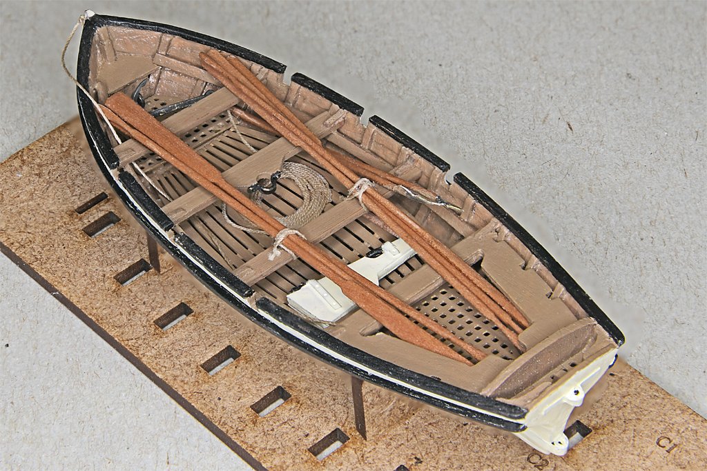
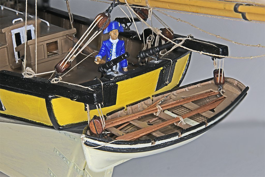
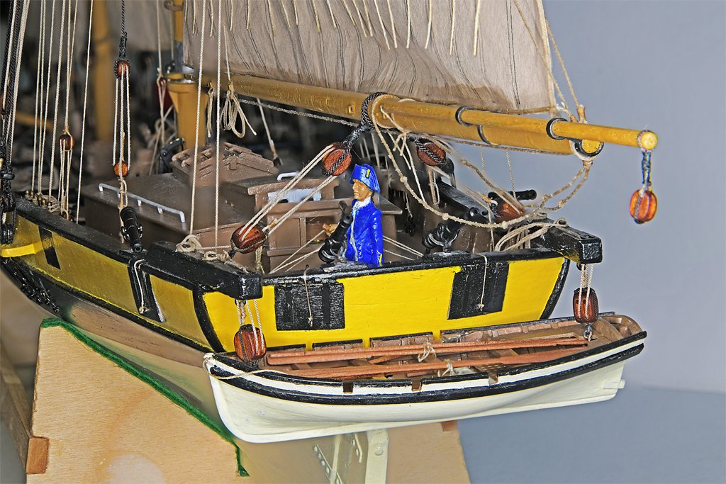
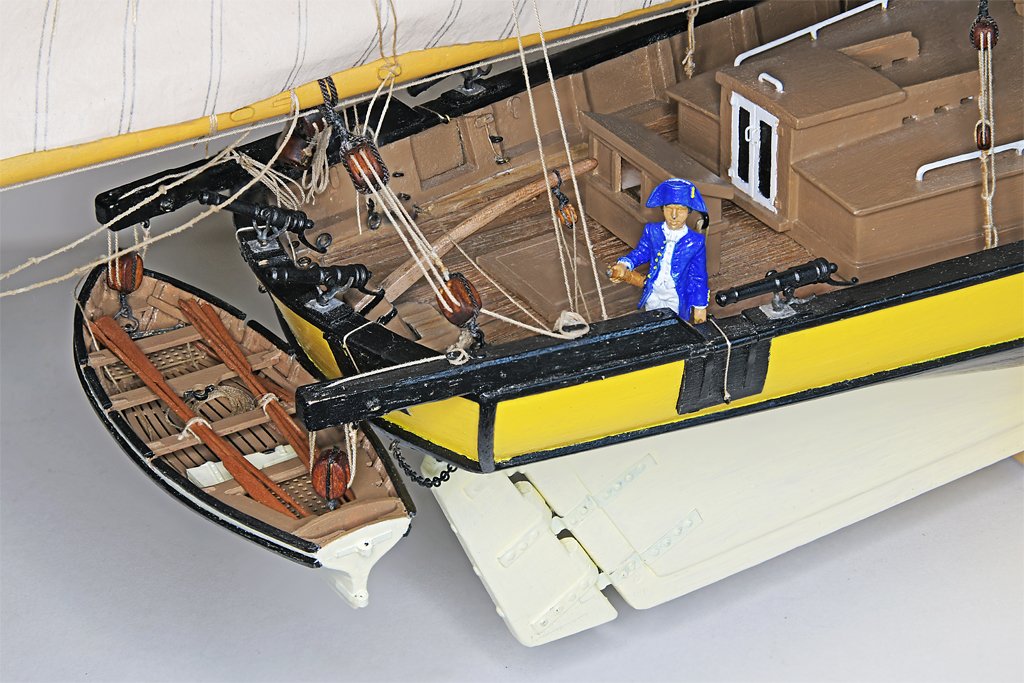
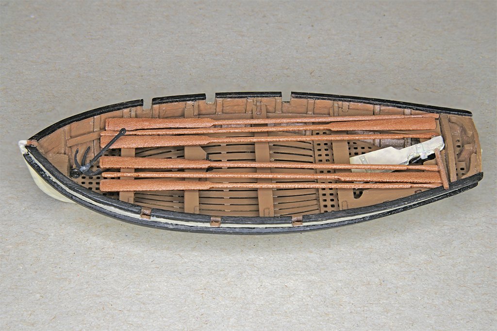
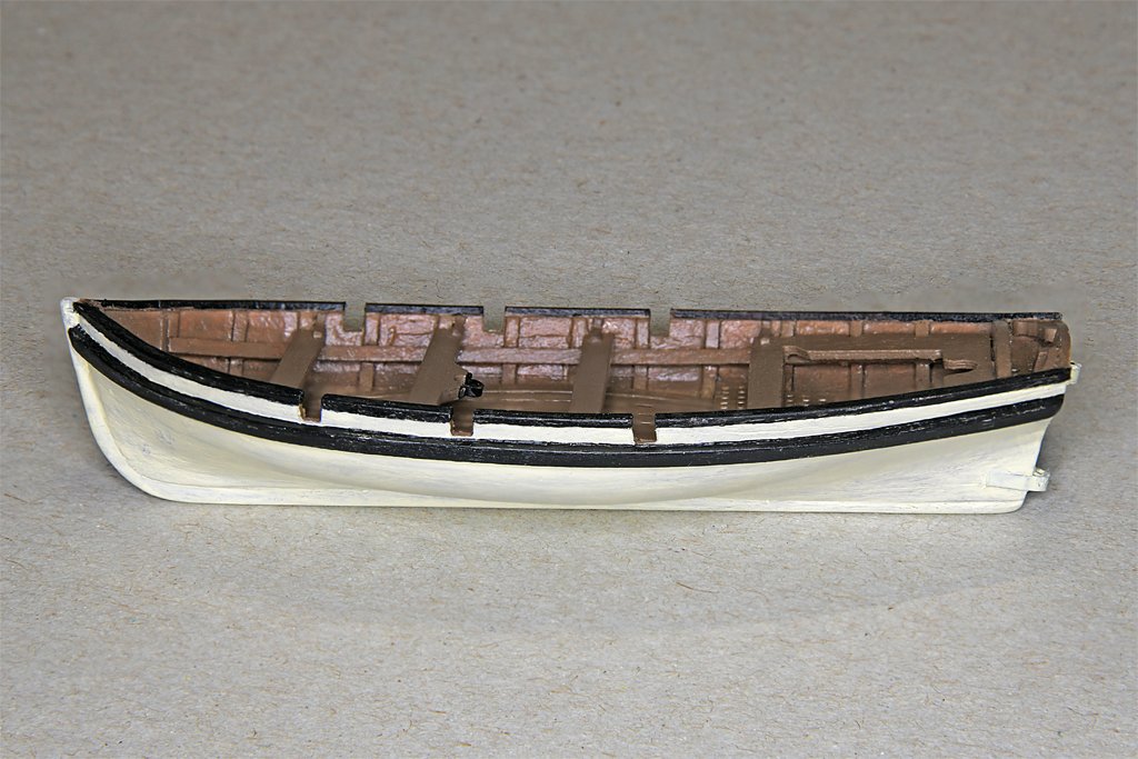
The boat is finished. I stowed the oars, rudder, anchor and boat hooks as if the boat was ready for lowering from the davits. The ship's port anchor is rigged as if it has just been fished from the water, and the sails are set as if the ship has just gotten underway. So the boat is rigged for "sea and anchor detail" (I don't know if it was called that in the early 1800s). The Vanguard cutter is just the right length for hanging under the boat davits. Unfortunately, the ratlines did not rig themselves while I was distracted building the boat, so I must now go back to that drudgery - unless I can find something else to work on.
-
You have marked some pretty deep slots in the bulkhead pieces. If the slots are tight "slip fits" when they go onto the keel pieces they should straighten out the keel pieces vertically. What really matters is that the keel is straight longitudinally (lengthwise) so you don't end up with a banana shaped hull. Clamping the bottom of the keel between two stiff pieces of wood or metal angle will hold it straight while installing the first few planks along the bulwarks or deck sheer. After this the planks should hold the bulkheads in proper alignment.
-
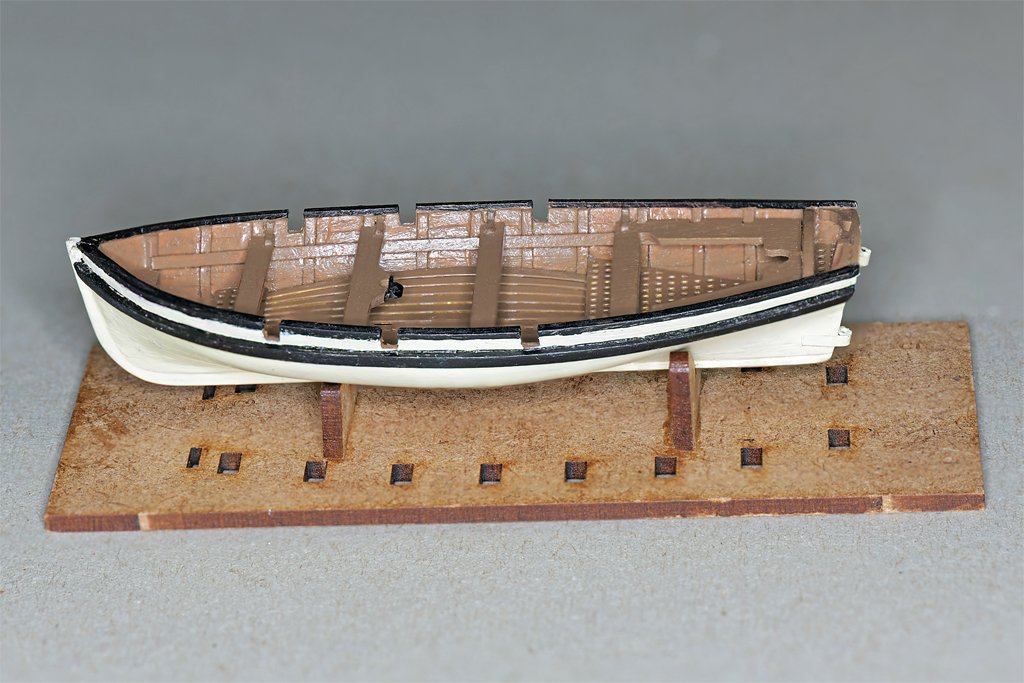
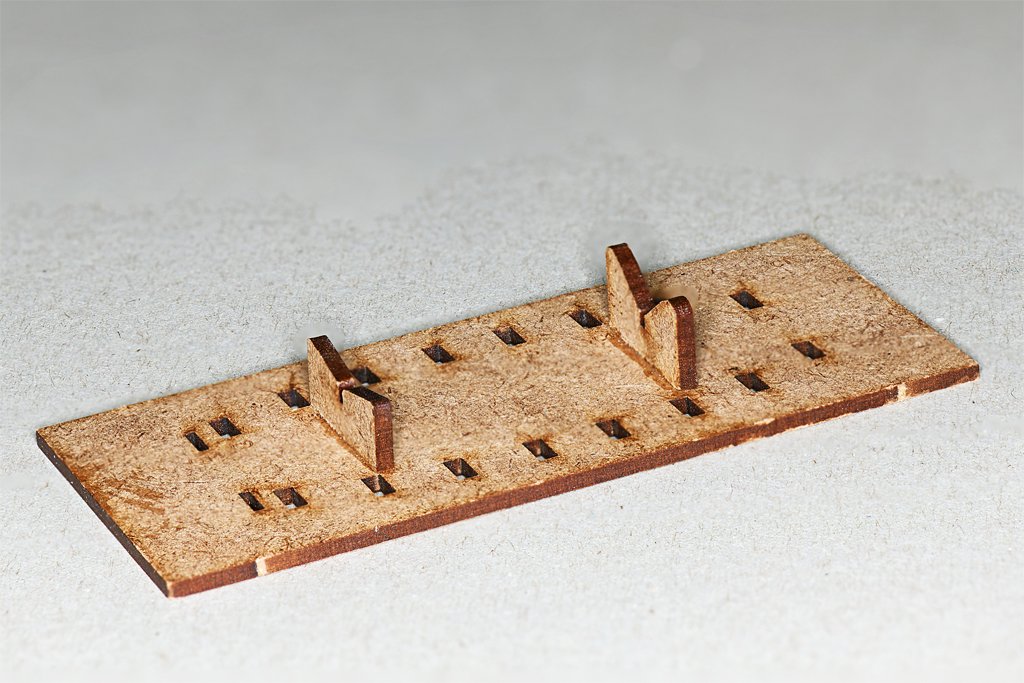
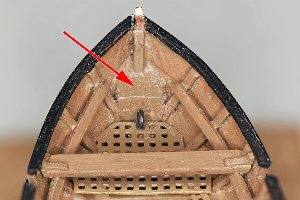
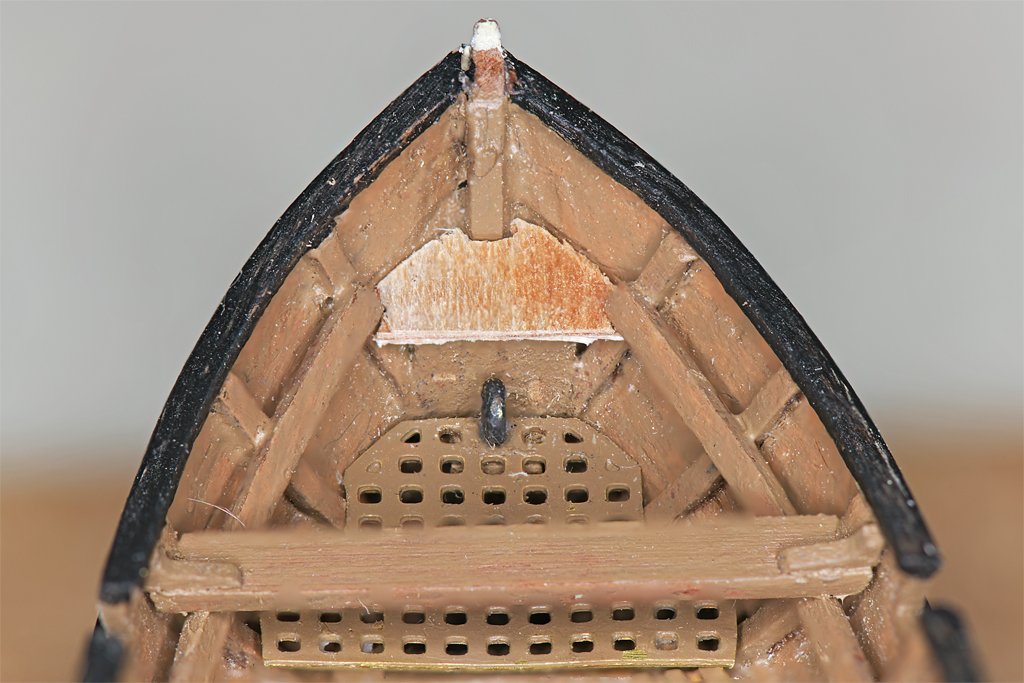
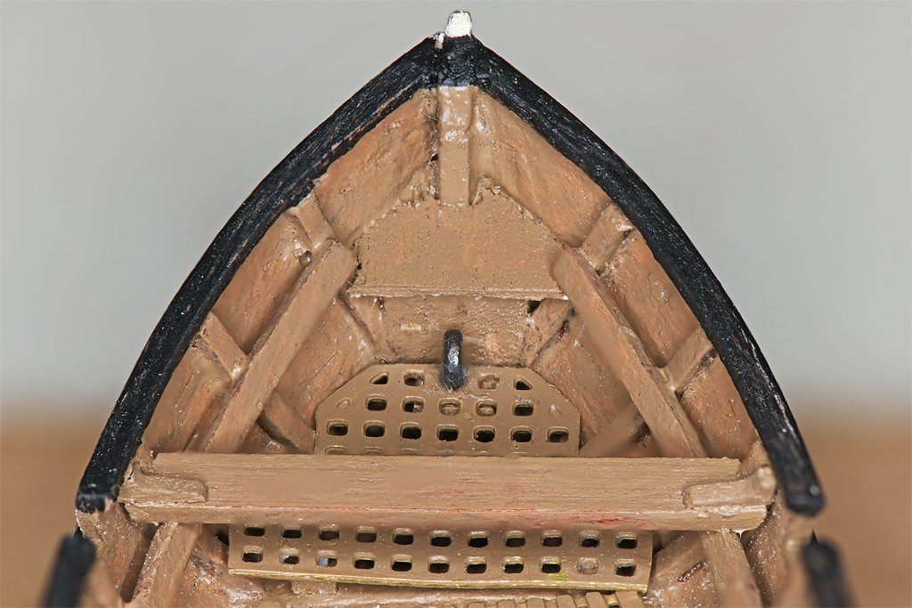
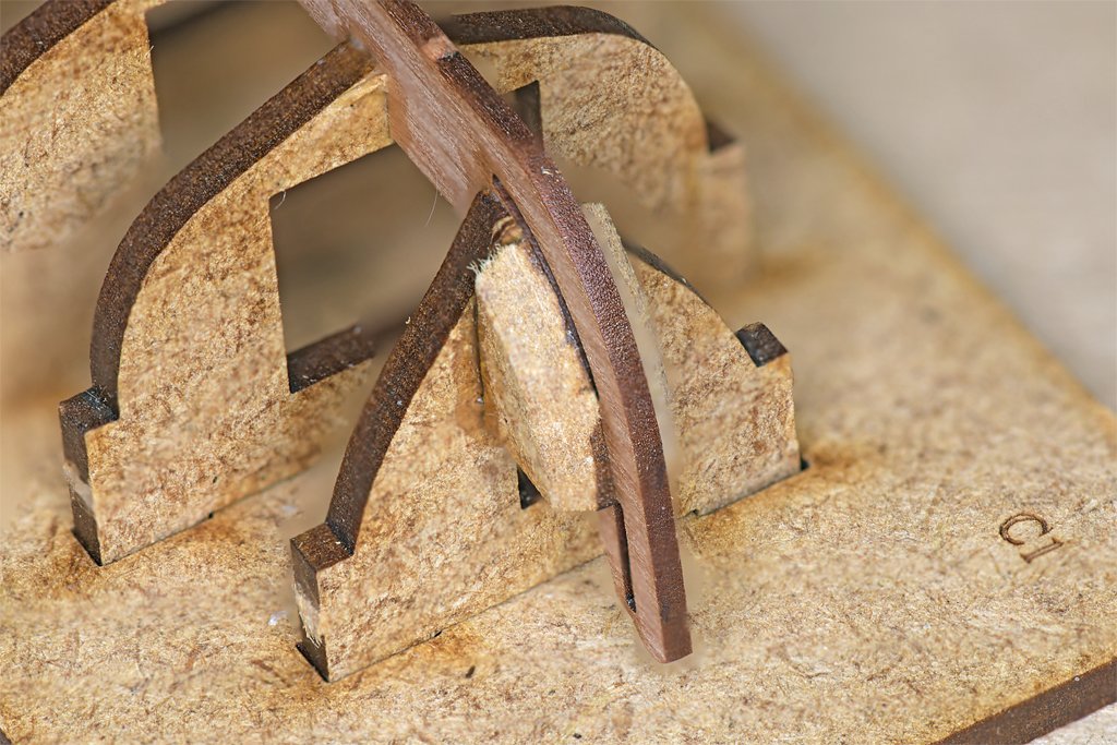
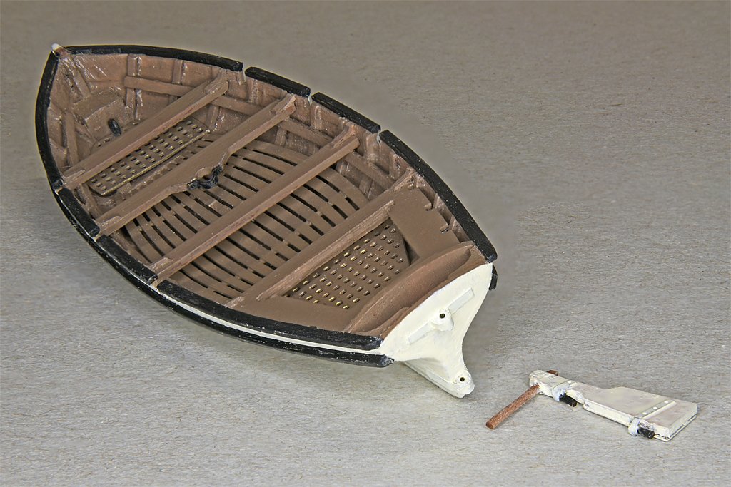
ADDENDUM Although the kit build is finished there was one fiddly bit I just couldn't let pass. At the bow is a "chunky" box-like bit (red arrow in left photo) that just doesn't look right. It is the remnants of the MDF filler pieces that were glued to the stem to support the bow planking (right hand photo). I considered trying to remove them when I was removing the MDF bulkheads. But they are about all that supports the planks at the bow. Trying to carve them out seemed to be tempting fate (and Murphy), so I left them. But plans for ships' boats don't show this box at the bow. Some boat plans do show a small deck at the bow. It is sometimes across the top of the planks, as an extension of the cap rail, and sometimes lower. I shaped a scrap piece of 0.012 inch (0.3 mm) plywood to fit the space and glued it in with Titebond Cement. Actually, I think the piece was a scrap of 1/64 inch (0.4 mm) plywood with one of the three layers removed. You can still see the aft face of the "box" beneath it if you look, but this seems to me to be more "prototypical" looking, if not actually accurate (the box certainly wasn't typical). Something I omitted from the build description was two pieces in the 2 mm MDF sheet, parts C12 and C13. These are boat cradles, possibly for use in Vanguard's ship model kits. After the hull with bulkheads is removed from the base these can be glued to the base to make a boat stand. This is handy for holding the boat steady while you are working on the interior.
- 54 replies
-
- 6
-
-
- 18 ft cutter
- ships boat
- (and 1 more)
-
I bought some very nice 9mm bronze belaying pins from Ages of Sail, 20 per package for US$9.12. Part number AM4101/09. I think these are Amati parts. Unlike some other brass belaying pins I have, these are very uniform size.
-
John, It is frustrating when I build something and then realize I did it backwards! But at least you caught the mistake before it went onto the model. And of course we have to fix the problem or it will gnaw at us forever!
-
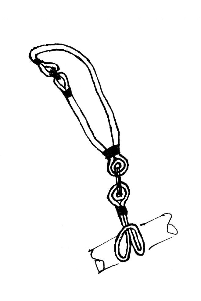
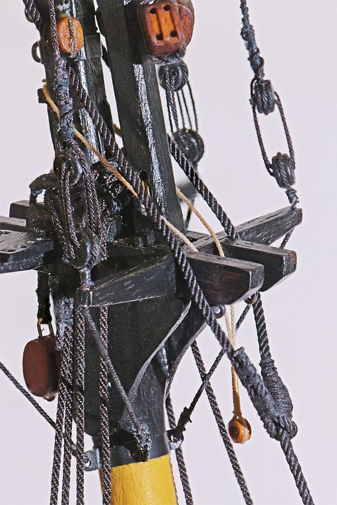
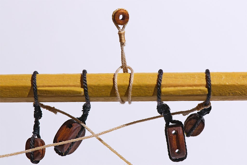
What type of vessel and what period? This is one way larger yards were suspended. The upper part of the sling wrapped around the mast head above the shrouds. Some references say the ends had eyes that came together on the starboard side and were laced together as shown here. The sling had an eye with a thimble at the lower end. The lower part was tied around the yard with a "larks head" or "cow hitch" knot. It had a thimble in the upper part, with the ends fastened together with seizing at the thimble. The yard could be hoisted with lifts and when in place the two parts of the sling were laced together through the thimbles. Smaller yards were suspended from a halliard. It could have an eye with a thimble in the upper end, and the yard could have a similar larks head and thimble rigging.
-
The boat kit build is finished. Now I need to arrange the accessories in the boat and hang it from the stern davits. Oh, I broke another plastic hook trying to fit the boat tackle into the boat.

-
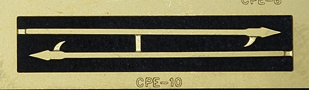
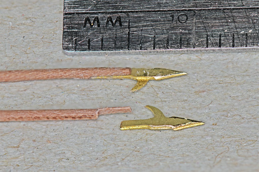
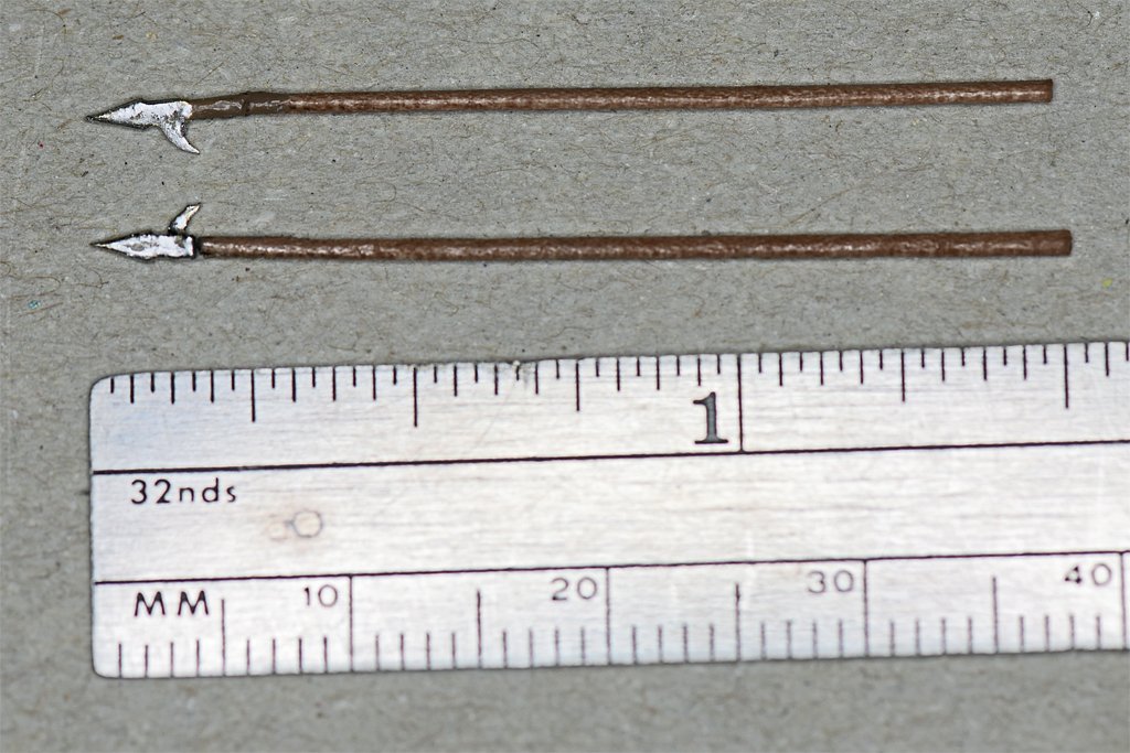
Thanks everyone! And Kevin, I think Vanguard Models deserves most of the credit. It is a very good boat kit! The last detail is the boat hooks. These photo etched pieces would be good enough if you just painted the handles a brown wood color. However, at 1:48 scale they were only about four feet (3.6 meters) long, and if I recall correctly from my sea going days they were really about 6 feet (2 meters) long. I decided to try to make wooden handles and use just the photo etch tips. For this I cut some of the 0.6 mm pear "sprue" that was between the oars in the laser cut sheet. I carved, scraped filed and sanded them into cylindrical handles quite a bit longer than needed. The tips of the photo etch pieces were filed to make edges to the point. Then the tips were cut from the longer handle part. I filed one side of the wooden handle end flat and less than half the diameter of the handle. Then the tip of the photo etch piece was attached to the flat with CA gel. The parts were cut to a scale 6 feet (1.5 inches or 38 mm) and the wooden handle was coated with shellac. When that dried I painted the tips with silver/chrome paint. A bit of brown paint was applied to the brass piece below the tip on the opposite side from the wood to hide the brass "shank.". This completed the build. I will arrange the pieces for stowage in the boat in the topsail schooner build. Here are a few thoughts about this build. 1. I didn't taper (spile) the planks correctly. This was trickier than tapering planks for a ship build because cutters were designed to be very broad relative to length. This boat was 87 mm long and 32 mm wide, or a length to width ratio of 2.7:1. The distance from keel to the top of the planking was 22 mm midships and 16 mm at the bow, so the planks should be tapered to only about 3/4 as wide at the bow as midships. But I put the top plank and the garboard strake on full width, requiring even more taper for the remaining planks. The laser cut planks were about 1.8 mm wide and the remaining 9 planks needed to be trimmed to about 0.5 mm at the bow. The stern posed a similar problem. This is pretty small, and an error of 10% (0.05 mm) that would not be a problem on a full sized ship model planking job can cause real problems on this small boat. I was pretty cautious while trimming the thin planks, and didn't remove enough wood on some of them. I didn't realize for a while how errors were accumulating. So I ended up using a filler plank. This wasn't the kit's fault, and it really didn't matter since the hull was painted and the interior deck pieces hid the filler piece. But if you plan to build the boat with bright wood finish you should pay closer attention the the spiling. 2. The rear seat part was very fragile, and broke several times along the grain at the narrow front part. It doesn't respond well to repeated handling. If I had placed the seat into the hull before placing the ribs there would have been no need to cut the notches to fit around the ribs. That would have decreased the probability that it would break. The rear part of this seat wasn't wide enough to fit from side to side in the hull. This probably was caused by my placement of the seat support strip. The instructions say to position it 3 mm below the top of the planking, but 3mm along the angled surface of the planking or 3mm vertically? I marked it 3mm along the surface, so that may have made the rear end too high relative to the boat overall. The piece was pre-shaped by heat bending before being installed, so it fit nicely against the ribs. But while I was gluing it to the 12 ribs the aft end may have creeped up a bit. It wasn't noticeable, but this also could have caused the rear of the seat to be too high in the hull, and therefore not wide enough. 3. I suspect most of these builds will be part of a larger ship build. Consequently they should be constructed without the rudder in place on the transom. It would be nice to have both options in the kit parts without having to modify the rudder as I did. But it wasn't hard to modify the kit rudder to be stowed in the boat. 4. I should have etched the brass photo etch parts or used a primer that adheres to brass. The acrylic paint that I used rubs/flakes off the smooth brass surface. All in all, the kit produced a very nice small boat.
- 54 replies
-
- 7
-
-
- 18 ft cutter
- ships boat
- (and 1 more)
-
I suspect "they" call me some other things too ... In truth, I am just a student of schooner design.
-
Nice work! I usually cut thin (0.003 - 0.010 inch, 0.08 - 0.25 mm) brass sheets this way to get narrow strips. I normally clamp the sheet and a steel ruler to the bench edge but I think I will try the double sided tape. I save old #11 blades for cutting the brass. They usually have broken tips and the resulting point scores the brass easily. I will have to make a lot of deck equipment for my MSI build and I can see I need to get a photo etch bending tool. What brand are you using?
-
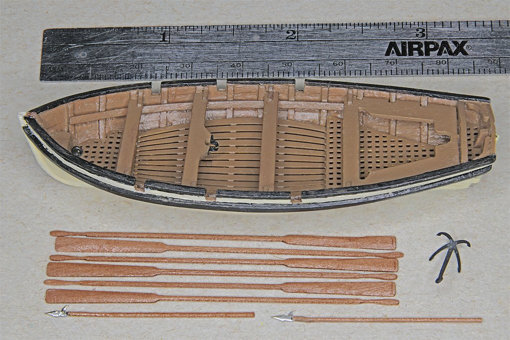
I did a little surgery on the rudder to remove the gudgeons and straps and add the pintles. Then I made some new straps and gudgeons and installed them on the transom. The oars were filed and sanded to make the handles round and taper the blades. The second photo shows the oars, rudder and anchor stowed in the boat temporarily. Things will have to be rearranged a bit to allow the boat tackle to hook to the eyebolts. I think the anchor should have a rope attached with the line coiled on the deck. And the boat should have a painter on the bow. I am still trying to decide how to make wooden shafts for the boat hooks. And I painted the boat, using the same paints that were used on the schooner model.
- 54 replies
-
- 6
-
-
- 18 ft cutter
- ships boat
- (and 1 more)
-
I don't know what that thing was made of. I looks a lot like sawdust mixed with glue that was pressed into a mold. Not everything in the kit was bad! I have no complaints about the quality of the wood - except the thickness of the deck planking strips varied quite a bit. That just meant a bit more sanding to get everything smoothed out. They did scrimp on the bulkheads - not enough midships - but I added a couple more to ensure that the hull planking came out OK. The hull planks were a good quality wood, but I am not sure what it was. The cannons were very bad. I have never seen anything like that in real life. And the gun carriages were a joke! But the anchors were nice - after I filed away the mold flash. The kit did supply some thread for rigging and "standard" low quality blocks, but I replaced it all with Syren products. The masts and spars were ordinary dowels. But they were too short for the extreme American rigging. They would have been OK for a British schooner build for the late 1700s or early 1800s. I replaced them all. The kit had a fairly nice flag, but it had 48 stars and 13 stripes as was used in the mid 20th century. That was just cheap! For my 1815 build I needed a 15 star flag with 15 stripes. This was a cheap kit, and I knew it when I bought it at a local hobby shop. This wasn't my first kit build. I expected to have to correct a lot of things. Basically it was just a supply of wood for a ship model.