Dr PR
-
Posts
1,504 -
Joined
-
Last visited
Content Type
Profiles
Forums
Gallery
Events
Everything posted by Dr PR
-

Terminology Confusion - Hounds, Cheeks and Knees
Dr PR replied to BANYAN's topic in Masting, rigging and sails
Pat, I was already wrestling with this when I read your first post so it was easy to share. Actually, I think some people may use "knees" for "cheeks" that do not have separate "bibbs." I have found only one author who called the cheeks "knees" and in his drawings they were trapezoidal and didn't resemble actual knees! Metal masts had single piece metal cheeks. -
Terminology Confusion - Hounds, Cheeks and Knees
Dr PR replied to BANYAN's topic in Masting, rigging and sails
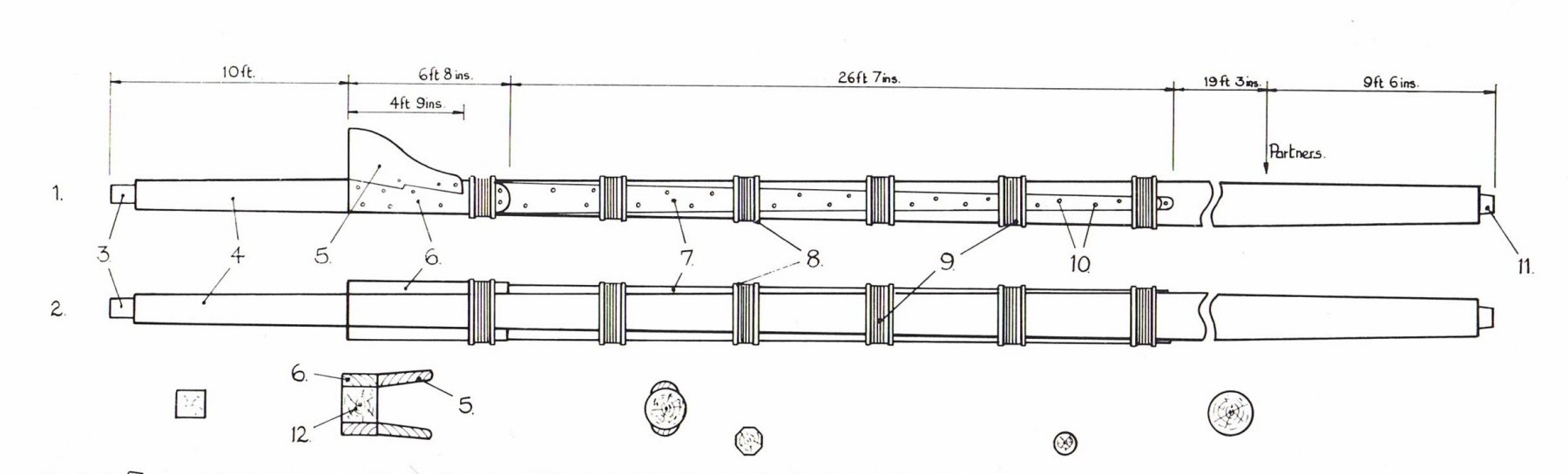
Here is an image from the Anatomy of A Ship series for the HMS Granado. The associated text gives these definitions (by numbered part) for the main mast: 1 Mast side view, 2 Mast front view, 3 Tenon for mast cap, 4 Lower mast head, 5 Bibs, 6 Cheeks, 7 Side fishes, 9 Wolding, 12 Cross section of the mast at the hounds. There is no clear definition of the extent of the "hounds" other than it is some part of the square section of the mast where the cheeks attach. In other drawings in the book "hounds" are just "rigging stop" attachments to the mast to support rigging that is tied around the mast. The cheeks are attached to the mast with bolts and woldings, and the bibs are attached to the cheeks. This seems to be the most consistent use of the terms. On smaller or later ships the cheeks and bibs may be a single piece. Instead of a longer piece extending down the mast and secured with woldings, the cheek may be a single knee-like piece that is bolted to the flats on the mast.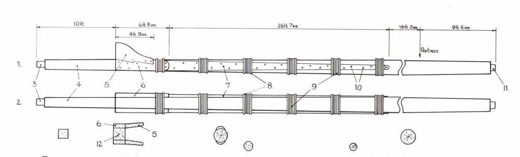
-
Terminology Confusion - Hounds, Cheeks and Knees
Dr PR replied to BANYAN's topic in Masting, rigging and sails
Pat, I have been researching this a bit more. Cheeks, bibbs and hounds are terms that are used differently by just about every author. Hounds are the part of the mast structure directly below tops - that is pretty uniform for all authors I have looked at. However, exactly what the hounds are is pretty vague. Some authors say the hounds include the cheeks and bibbs. Some say it is just the part of the mast at the top of the cheeks or bibbs. One author refers to sheaves set into the cheeks as hounds. Another seems to consider anything on a mast that is intended to prevent lines or structures from slipping down the mast to be hounds. And one author says the top is built around the part of the mast call the hounds, implying that the hounds are above the cheeks! Take your choice. Underhill is the only author that used the term "hounds" to mean a specific point along the length of the mast, and it is for the purpose of defining the diameter/cross section of the mast at that point. The terms "cheeks" and "bibbs" are used interchangeably for the attachments to the masts at the hounds that support tops and cross trees. Most authors refer to the main part that is attached directly to the mast as the "cheeks." This may be a simple single piece knee, where the forward curved part may be called the bib. Or it may be a long piece secured to the mast by woldings that is shaped at the top to form a "cheek." A "bibb" or "bib" is a piece attached to this cheek to create a forward extension to support the trestle-trees. One other thing to be aware of is that the knees that support the head timbers at the bow are also called "cheeks." Some call these "head cheeks." So the term "cheek" is about as ambiguous as can be. -
Terminology Confusion - Hounds, Cheeks and Knees
Dr PR replied to BANYAN's topic in Masting, rigging and sails
Pat, In "Masting and Rigging the Clipper Ship and Ocean Carrier" (1972, page 5) Harold A. Underhill gives the following definitions of mast parts (bottom to top): Note: In this case the "mast" is a single pole or spar, such as the lower mast, the top mast or topgallant mast. Heel: the bottom of the mast. Partners: where the mast passes through the main deck. Hounds: the top of the cheeks, where the trestle-trees* rest. Head: the part of the mast between the hounds and the highest part of the mast at the cap. Doubling: the part between the hounds and the cap (the head), where the lower mast and upper mast fit side by side. Hounded length: the part of the mast between the heel and the hounds. Measured length: the overall length from heel to highest point at the top of the cap. Measured length = hounded length + head. These terms should apply to mid 1800s British and American ships. **** The mast cheeks are supports for the top that are fastened to either side (port/starboard) of the mast. The shape, how they are attached to the mast, and additional parts varied with the type of ship and the period. In "Historic Ship Models" Wolfram zu Mondfeld has drawings of several arrangements. Continental ships had single pieces called "bibbs" attached to the sides of the mast (p 219). English top supports were built up with a piece attached to the sides of the mast itself (the "cheeks") with the bibb pieces notched into the front of the cheeks. The whole collection of pieces that support the top are typically referred to as the "cheeks" or "mast cheeks" (p 221). **** * The "top" is the platform near the top of a mast. The trestle-trees are the fore-aft members that the mast top is constructed on. They support the side-to-side cross-trees that support the decking in the top. Trestle-trees rest on the top edge of the cheeks. So the hounds were the line at the top edge of the cheeks and the bottom most part of the top. In this Underhill is quite specific. In a drawing showing the top and the cheeks he has an arrow pointing from the label "hounds" directly to the line between the top of the cheek and the bottom of the trestle-trees. The mast top itself is above the hounds. Hope this helps more than it confuses! -
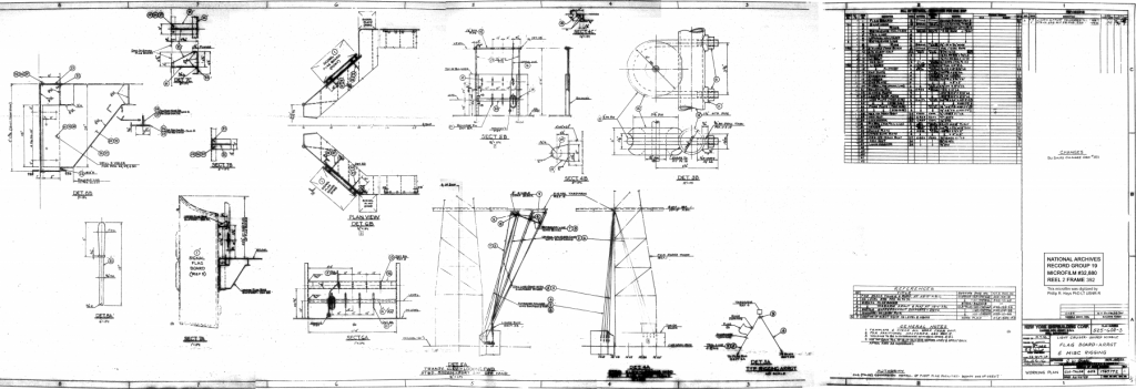
YC, Here is a blueprint for the "flag board" (also known as the flag bag) on a Cleveland class cruiser guided missile conversion in the 1950s. I suspect (but I am not certain) it is the same flag bag that was used on cruisers during WWII and was reused after the conversion. It is the same basic design shown in the photos Bob posted. This shows the general shape and size of the flag bag, and is an example how it was arranged with respect to the signal mast and halyards. This is a prettty large drawing showing the details clearly, but it looks like the Forum reduces it drastically. Contact me through this link and I'll send you the full sized drawing: https://www.okieboat.com/Contact page.html I might even find some more photos of cruiser flag bags.
-
Jo, Did you "paint" the edges of the planks before putting them in place, or were the grout lines drawn on after the planks were on the deck? Phil
-
Jo, Nice work! The deck looks good. I had similar problems on my latest build with varying thickness of the deck planks. It just takes a lot of sanding to get them smooth. I finished with 0000 steel wool and a coat of clear lacquer. How did you make the black grout lines between the planks? They look very good. I second what Popeye said about being careful with the bulwarks. With the frame ribs removed they are vulnerable to cracking. If that happens it can be difficult to get the planks to align properly again - they will have minds of their own, like herding cats. I would put the replacement frames on as soon as possible to add strength. If they protrude above the bulwark a bit you can sand them down before adding the cap rail. Also, having the frames in place and sanded to the proper angle will cause the cap rail to fit correctly. If you attach the cap rail first and then try to place the frames the cap rail might be at the wrong angle and it will be more trouble trying to cut each frame the proper length.
-
Redrawing of Ship Plans using Fusion 360
Dr PR replied to Castos's topic in CAD and 3D Modelling/Drafting Plans with Software
The main problem with laptops is inadequate cooling of the CPU. The i5s and i7s generate a lot of heat when all of the cores are running 100%. The tiny fans in laptops cannot remove all of this heat fast enough. To avoid meltdown (literally!) the processors have a protection circuit that stops the CPU clock momentarily, stopping heat production to allow the fans to catch up. This slows down program execution significantly. The more heat that is generated the more frequent the clock delays. If stopping the clock doesn't work the CPU voltage is reduced (higher voltage makes more heat). But some components will not work correctly at lower voltages so the system eventually crashes (BSOD - Blue Screen Of Death). When Win 7 came out laptops began crashing regularly with the BSOD. Oddly, this would happen only on certain days and times. In it's effort to make computers more useful Microsoft made hard drive file defragmentation automatic, not requiring the user to start it (because most users didn't even know why it needed to be done or when to do it). Unfortunately, when the weekly scheduled defrag started all cores were run at 100%, processors overheated and the computer stopped working. This happened only on laptops and not on desktop machines that had lots of fans and coolers for the CPU. Win 8/10 came out defrag was implemented bit by bit, periodically while the computer was running. This kept up with the fragmentation of files so the defrag process never lasted long enough to generate enough heat to crash laptops. But it does slow things down every now and then. **** Laptops are useful for very slow operations, such as typing and reading email, where the processor is waiting on the user most of the time. CAD programs, image rendering, complex spreadsheets and such can run the processors full time, and that causes the CPU to overheat, resulting in very sluggish performance. I have a 2 GHz i7 laptop and a 3.4 GHz i7 desktop. The desktop is many, many times faster than the laptop for complex CAD work. It has 10 fans in the chassis and a liquid cooler for the CPU, and I have never seen the CPU slow down because of overheating. The fans normally run very slowly so they are barely audible, but for really long complex operations the fans sometimes start roaring like the thing was about to lift off! -
I tend to stick to one project at a time, but within a project it is necessary to plan ahead. You really need to be familiar with every step of the build before you start, otherwise you may find that you misunderstood how one of the later parts fits into the whole and find that you have to go back and reconstruct something. For me this is very frustrating! In many cases I create my own plans for parts and assembly, even if it is a kit with plans. Kit plans often leave a lot to be desired! I read about how things worked on the real ships. That gives me a much better understanding of what it is I am building, and how it fits into the whole model. For example, on my current build, while I was attaching the channels and chain plates to the hull I needed to know the angle of the shrouds from the mastheads to the channels in order to get the angles of the chain plates right. This required me to determine the heights on the masts where the shrouds attached, and that required a bit of study of the mast assemblies. I didn't actually construct the masts, but I learned how to do it. Having said that, I am planning another 1:96 scratch build project of a guided missile cruiser. No plans existed for the ship so I worked 14 years to research and create a very accurate 3D CAD model to be used to create plans. After that I was pretty much burned out for a while on the cruiser project, so now I am "relaxing" with a revenue cutter kitbash build. But I started the kit build before I began working on the CAD model of the cruiser! One of these days I will restart the 1:96 scale project, and I suspect it will take several years to build it. I may alternate between the two builds in order to get a change of pace. Who knows which will be completed first? The important thing is to enjoy what you are doing. If you lose your enthusiasm for one project, that is the time to put it on the shelf and work on something else. The first will keep, and will be there when you again have interest. Besides, in the interim you may discover something about the shelved project that will help you build a more satisfying model.
-
Welcome, and congratulations on your first build. I started building wooden boats and ships from scratch when I was a kid and quickly learned to be disappointed in the results. Get used to the idea that your first build will not be perfect, no matter how hard you try. It will be a learning experience, and that will help make your second build much better! If something doesn't come out "right" in your opinion (and your opinion is really the only one that matters) think about it and decide what you think is not right and why. That way you won't make the same mistake again. I am working on my sixth large scale wooden ship build (the third from a kit) and there are things about it I am not totally satisfied with. I'm still learning, and having fun! The only bit of "advice" I would offer is to study each part of the ship and learn what its function was. What did it actually do on the real ship and how did it work? This often gives insight into how the part fits into the whole, and that can go a long way to fill in the gaps in the instructions. And, of course, ask questions of the modelers here and on other ship building forums. If you are having a problem you can be sure someone else had been there before and may be able to solve your problem. Happy modeling!
-
This may be a bit late for your build, but something to think about when using rub-on lettering. I have always worried that it might some day peel off. And often I have not been able to find the right color in the font I need to use. I use the rub-ons as a type of stencil. First I paint the desired lettering color on the surface and let it dry. Then I add the rub-on letters. Then I paint the background color over the letters. After the paint dries I use masking tape to lift off the rub-on letters, leaving the desired font and color. This has the advantage of being permanent lettering, and the letters have no apparent thickness - important in really small scales. Since you seem to be staining the wood this technique probably won't work, but it is something to keep in mind. Phil
- 241 replies
-
- 1
-

-
- mermaid
- modellers shipyard
- (and 1 more)
-
Valeriy, Beautiful work! I love working with brass and solder, and you are doing an excellent job! Commercial sanding sealers typically are clear paint with a fine powder - like talc - mixed in to fill in the pores in the wood. However, the white talcum powder can make the wood a lighter color. If the wood is to be painted with an opaque color this isn't a problem, but for "bright" or unpainted wood, like decks, it can create an unnatural look. You can also mix very fine wood dust from sanding into clear paint and use it to seal the wooden decks. Then after sanding and finishing with fine steel wool the wood retains a natural color. If the deck planks are fine grained you can just use clear paint without a filler.
-
Carl, I have been using "craftsmart multi surface premium satin acrylic" paint that I got at a local craft store. The color is "White/Blanc/Blanco." Just plain white. It is pretty thick, but after thinning a bit with water it worked well with my airbrush. Again, I would not recommend using this paint for modeling. It is very soft after it dries - even after a month or more. It scratches easily. Note: After several months it dried pretty hard. I have even considered stripping all of the paint and starting over with lacquer. Ug! Another option would be to spray over the acrylic with another coat of clear satin lacquer or enamel. But this would probably be asking for trouble - I would have to experiment first. The acrylic undercoat would still be soft. I suspect the problem is that I used a lacquer based sanding sealer on the wood (except the deck) and after the sealer I sprayed the entire ship (including the deck) with clear lacquer. These were model airplane paints (dope). I guess the acrylic just doesn't cover well over the lacquer.
-
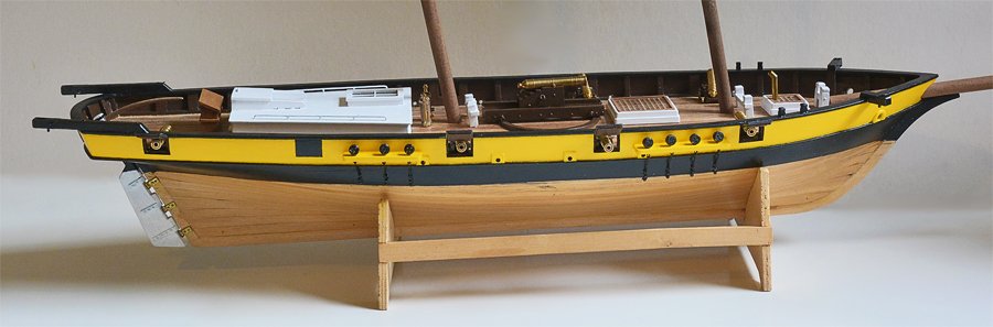
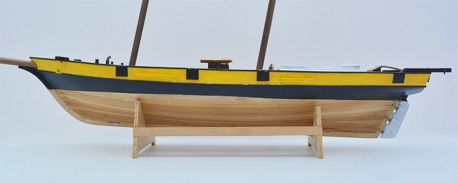
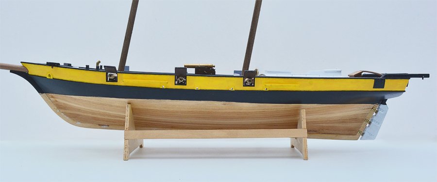
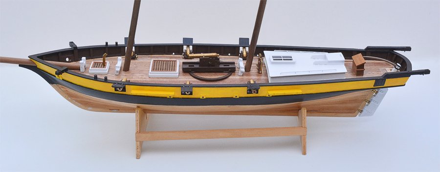
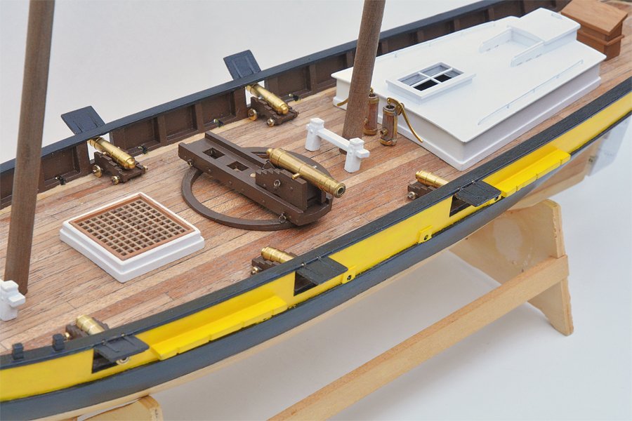
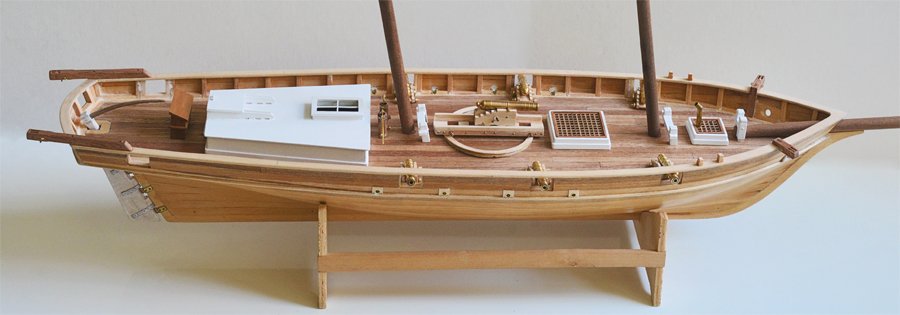
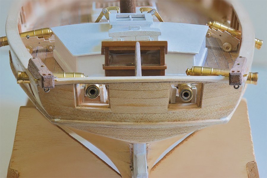
Painting has been a tedious chore. The acrylic paints I used are very slow drying, and even after dry they are very fragile. I can scrape the paint off with my fingernail! Should have used lacquers or enamels!! But I have added the channels, deadeyes and chain plates and finished the basic painting. I also painted the dummy gun ports outboard the deck house. Here you see the six pounder carriage guns positioned for a four gun broadside. The channels and chainplates came out pretty good. I need to touch up the flat black enamel on the metal parts. The chainplates are exposed to handling and are easily bent. I need to do a bit of straightening. On the other hand, maybe they are just "weathered" like might have happened on the real ships. I still do not like the dark brown paint on the bulwarks and cannon carriages, but I don't look forward to trying to paint over it with a lighter shade of brown. I also think the deck house and other deck "furniture" probably should also be brown. From what I have read white deck fixtures didn't come into use until the 1830s.
-
Try looking for hypodermic tubing - like is used to make needles. Several places on line sell it. It comes in diameters down to 0.006" outside diameter and 0.002" inside diameter. For comparison normal notebook paper is about 0.003" thickness. 24 lb printer paper is 0.004" thick.
- 467 replies
-
- 3
-
-
- mikasa
- wave models
- (and 1 more)
-
Photo Etching - do it yourself
Dr PR replied to Dziadeczek's topic in Metal Work, Soldering and Metal Fittings
I have etched a lot of printed circuit boards and brass photo etch parts - they use the same processes. Here are some thoughts about photo etching. I have used the Micromark system. It works mostly, but really hit or miss. The main problem is the photoresist. I had great difficulty getting uniform development across the work piece, so parts of the sheet would etch correctly and other parts wouldn't etch at all. Even after it is developed a thin invisible film may remain and this slows or prevents etching. Also, the maximum brass work piece size is about 3" x 3". Larger pieces came out OK, but I was never able to get fine line pieces to etch evenly. I wasn't too happy with it. I had no problems getting good alignment for images on both sides, but I have been making my own double sided circuit boards for about 35 years and have that figured out. I place registration targets in three corners of the film for front and back pieces. I tape the back side to a glass window (or back lighted glass sheet) with blue painter's masking tape. Then I place the front film over it, carefully align it, and then tape it on one edge to the back sheet. Then I slip the brass sheet between the two films for exposure. Do not try to print backwards on your printer. First invert the image in Photoshop, your CAD program, or whatever you are using to generate the artwork. I have used several inkjet and laser printers and some just do not print accurate scale. One HP laserjet always printed at 0.976 true size, so I always used a 1.024 scale multiplier. I used my CAD program to produce a 10 inch "ruler" and measured it with an accurate machinists ruler to determine the scale multiplier. Whatever printer you use be sure to open the printer dialog and set the highest quality print possible. This will place more pigment on the film. Print at 300 dpi or better. There are bunch of rules for metal thickness versus minimum line/spacing width. The thicker the metal the greater the potential for undercutting - etching metal in the interior of the sheet deeper into the piece than at the surface where the resist is. Faster etching helps reduce undercutting. Thicker metal etches more slowly. Use the thinnest metal suitable for the job. Stainless steel etches slower than brass. The last time i checked the rule for minimum etch widths was something like 1.2 times the metal thickness, So for a gap 0.010" wide the maximum metal thickness is 0.0083". Or with 0.010" thick metal the minimum etched gap width is 0.012". Use a good quality brass! Simple cold rolled brass sheet may have irregularities in hardness that causes some parts to etch slower than others. Any slight bends during the rolling process or handling will result in harder spots. Hard spots can happen if the rolling process stops or varies in speed. You need some method of eliminating the etched residue from the metal surface while etching. If you just lay the sheet flat in a dish the etched material will build up over the surface and slow or stop the etching process. I found the Micromark etch tank with a fish tank air bubbler to be pretty good, but it helps to swish the piece around in the etching solution occasionally. You can also remove the piece from the tank, wash it gently under running water (do not wipe) and return it to the etching solution, but be careful to not wash the photoresist off the metal! The etchant solution is usually ferric chloride - the same as used for making printed circuit boards. CAUTION: you MUST use plastic or ceramic containers for etching. The etchant solution will also etch metal trays! There are two types of photo resist. With one you design your photo masks so the exposed parts will resist etching (the Micromark process works this way). So your artwork will be dark where you want to remove metal (a negative). With the other the exposed parts will be etched so your artwork will be a "positive" with the dark parts being the part that is not etched. You have to match your artwork with the photoresist type. Use a bright UV lamp to expose the resist! This will allow a fast "flash" exposure. Dim lights will require long exposures and this seems to cause fuzzy outlines in the resist that cause unpredictable etch widths. **** For me I think I will go with a commercial photo etch shop, at least for anything that has fine line details. Phil -
MAST DIMENSIONS Not much progress to report. I am working on installing the chain plates and deadeyes in the channels. To do this I need to have some idea of the angles the shrouds and stays will make at the channels. For this I need to know the heights of the masts. I have been studying Chapelle's "The Baltimore Clipper" and "The History of the American Sailing Navy," Underhill's "Masting and Rigging the Clipper Ship & Ocean Carrier," and Mondfeld's "Historic Ship Models." One thing is clear, the dowels supplied with the Albatros kit for the masts are too short by at least 4 inches. The kit seems to be for a British schooner, and the Royal Navy apparently rigged shorter masts and less sail area than the Americans. There are several examples in Chapelle's books of Baltimore clippers with extreme rigging, while Underhill and Mondfeld show much shorter rigs. One interesting outcome of the very large sail plans of the American, and later British, Baltimore clippers is that they could be very unstable under some weather conditions. Because of the topsails on the fore mast the rigs were heavy forward. The ships usually were broadest forward near the fore mast instead of midships like most other ships. If the ships were running with a strong wind and also plowed into high seas, the ship could cartwheel end over end. One account told of a Baltimore clipper running alongside a larger ship when it suddenly dove down bow first, flipped upside down, and sank immediately with no survivors! The length of the main mast (foot to top) is based upon the extreme breadth of the hull. Rankine's version of Fincham's rules (Fincham was a British naval architect) gives a main mast length (heel to hounds - the "hound" is where the trestle trees of the top rest on the mast) 2.6 to 2.8 times the extreme breadth. Mondfeld (European) shows a shorter total mast length of about 2.3 for British warships in the early 1800s, but this is probably for larger three masted square riggers. The kit masts are closer to Mondfeld's dimensions. I am using Marister's data taken from actual ships starting on page 112 of "The Baltimore Clipper." In addition, I'll use Rankine's modifications to Fincham's rules for dimensions and formulas on pages 159 to 162 plus Fincham's tables in the Appendix. These should give me some realistic dimensions for the masts and spars. The hull is 75' 8" length overall (bow to transom), with a length between perpendiculars of 66' 5" and a 64' Line of Flotation (the distance between rabbits fore and aft on the load water line). The extreme beam is 19' 11" (19.916'). Using Fincham's rules maximum values: Main mast heel to hound = 2.8 x 19.916' = 55.77' The fore mast is 0.9 to 0.97 times the length of the main mast. Fore mast heel to hound = 0.97 x 55.77' = 54.1' The "head" of the lower mast extends above the hound to the cap. The head = 0.25 to 0.4 x extreme breadth. This gives a head for the main and fore masts of about 4.8' to 8'. Assuming a head length of 6' the resulting mast lengths are: Main mast = 56' + 6' = 62' Fore mast = 54' + 6' = 60' Marister's data for American schooners 60 and 62 feet between perps shows mast lengths of 58' for the main mast and 56' for the fore mast. A 57' long pilot boat had a 60' main mast. For the 66' model I will use a total main mast length of 62' and a fore mast of 60'. Main mast = 62' x 12"/48 = 15.5" on the model. Fore mast = 60' x 12"/48 = 15" on the model These dimensions assume that the foot of the mast rests on the keelson. However, in the Albatros kit the mast feet are actually much higher, so I will have to correct for this difference when cutting the actual masts. The model distance from keelson to main deck is 2.2". So the main mast will extend 15.5" - 2.2" = 13.3" above the main deck to the top. The mast foot is 0.91" below the deck, giving a total length of the model's main mast = 13.3" + 0.91" = 14.21". The fore mast will be 15" - 2.2" = 12.8" above the main deck, plus 1.14" below the deck to the foot, or 12.8" + 1.14" = 13.94" total. Both masts will have a top = 1.5". The top mast lengths are often the same for both masts. Drawings of Baltimore clippers show the top masts to be about half the length of the lower masts. Fincham says the length of top masts is 0.83 to 1.0 times the extreme breadth, with a pole head equal to 0.5 x the topmast length. I am not sure what the "pole head" is, but Mondfeld shows it as an extension of the top mast. Most Baltimore clipper drawings just show a longer top mast without a distinct pole head. The total length of the top mast and pole head would be about 1.5 times the extreme breadth, or about 30 feet for this model (7.5" at 1:48 scale). The sail plans of many schooners and Baltimore clippers show the total main mast height above the deck to be about the same as the length of the hull or a bit longer. The hull length of the model is about 19". With the main mast 13.3" above the main deck the top mast should extend about another 6". Including the 1.5" heel (the bottom part between the cross trees and cap), the top masts should be about 7.5" in length. Total mainmast height above deck = 13.3" + 6" = 19.3". With the more extreme rigs it would be a bit longer. I'll use 7.5" topmasts on both masts. Both Underhill and Mondfeld have tables and formulas for mast diameters and tapers that agree closely. The 62 foot main mast diameter at the deck would be 20 3/4", tapering to 15 9/16" at the hounds, with a 13" diameter head. The 60 foot fore mast diameter at the deck is 20", tapering to 15" at the hounds, and a 12 9/16" diameter head. The 30 foot top masts would be 10" diameter at the cap and tapering to about 5 1/2" at the head. On the model the mast dimensions will be (corrected for the shorter heels): Main mast: 14.21" long, 0.43" diameter at the deck, 0.32" diameter at the hounds, with a 0.27" diameter head. Fore mast: 13.94" long, 0.410" diameter at the deck, 0.313" diameter at the hounds, with a 0.26" diameter head. Top masts: 7.5" long, 0.21" diameter at the cap, 0.114" diameter at the head. Note: On topsail schooners and Baltimore clippers the fore mast was often larger diameter than the main mast because of the greater weight of the topsails and spars. I'll have to research this a bit more. All other spars are based upon the length of the masts, extreme beam or Line of Flotation. EDIT: I think the lower mast diameters given here are a bit too large. They are based upon rules for larger square rigged ships. Schooners carried a lighter load aloft, and most texts say schooner masts were smaller diameter than square riggers. To be continued ... EDIT: In "Masting and Rigging the Clipper Ship and Ocean Carrier" Harold Underhill says that schooner masts are only about 4/5 the diameter of masts for full square rigged ships.
-
Bruce, Thanks. I hope you will post the results of your planking experiments. I am planning a 1:96 model that will have 4 inch deck planks - about 0.040 inch or 1 mm at 1:96 scale. The black paper method I used on the current 1:48 build would be far out of scale and I will need to use a different method for the 1:96 model.
-
I have been painting the hull, and it was an unpleasant experience! I used acrylic paints from a local hobby store because I wanted to paint indoors during cool wet weather. After a week they are still very soft and do not adhere well. First I sealed the wood with a lacquer based sanding sealer. It dried for weeks before I painted with the acrylics. This might be part of the problem. I certainly won't use this combination again! I decided to use the black hull with yellow band described in Chapelle's books. It is similar to the image on the kit box, but with black above the waterline. The bottom of the hull will be white, like the rudder. Some of these ships were coated with white lead mixed with tallow. When (if) the yellow dries good I will paint a black dummy gun port midway between the aft two actual ports. I am afraid to use masking tape on the black paint because it scratches and lifts off very easily. All of the gun port covers open. I don't know now if I will rig them open or closed. Chapelle says they used a bright yellow for the stripe. At first I used a bright lemon yellow, but it was a bit garish. I painted over the stripe with a more modest "bright" yellow. Of course the actual colors used on ships was up to the Captain until about the 1840s, so any color is as good as another from a factual standpoint. Because masking tape lifts the paint, I had to paint the trim with a brush, and there were occasional irregularities at the boundary between black and yellow. The yellow paint did not cover well over the black (no surprise), but straight out of the bottle undiluted it took four or five coats to cover even a tiny bit of the black paint. Even the black required two or three coats to cover brush streaks. It took two weeks to correct all the minor mistakes. The interior of the bulwarks and gun port covers and the gun carriages are brown. This is supposed to be a medium brown, but it looks too dark to me. This color scheme is said to have been used in the American Navy up to about 1825. After that the stripe was white instead of yellow. Here is a closer look, with the six 6 pounder carriage guns run out and the pivot gun swung out to the side. I'll paint the carriage wheels brown eventually, and the cannons will be a flat black. Some of the ships had brass cannons, but I have read they were painted to prevent corrosion. I am having second thoughts about the white deck structures. From what I have read this didn't come into use until the 1830s or later. However, if you have ever served on a ship and had to walk the decks at night without much light while the ship was pitching and rolling you will appreciate how sensible it was to paint the structures white! Most models have deck fittings the same color as the bulwark interiors, but I don't like that dark brown color! To be continued ...
-
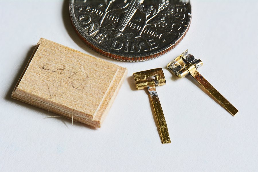
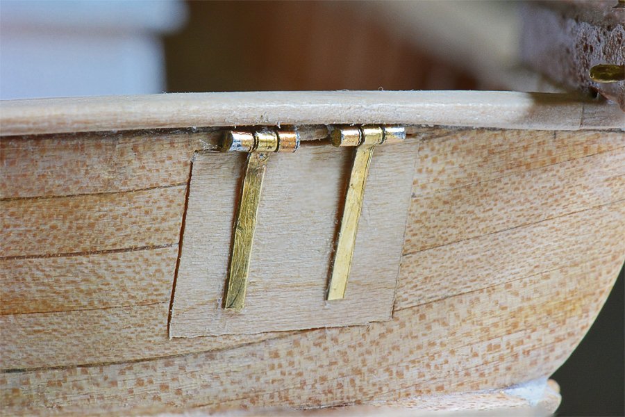
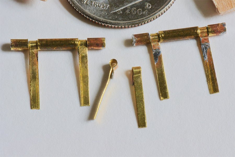
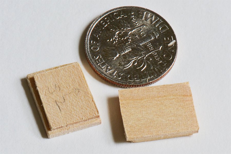
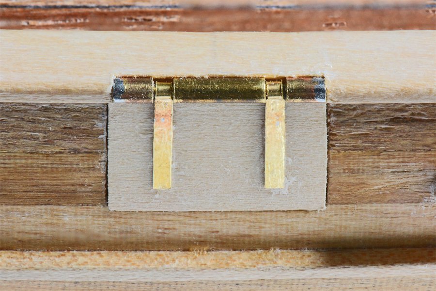
The aft gun port doors/lids posed a different challenge. The top rail curved upward to center so the top edge of the gun port was not tight against the rail as on the side ports. I thought the type of hinges I used on the side would be a bit too crude, so I came up with a different plan. The hinge straps are the same as for the side hinges. But instead of using brass tube for the fixed part I fashioned the hinge from the same 0.005 inch thick brass sheet as the hinge straps. First I cut a strip 0.150 inch wide, and bent about 0.030 inch of the end at a right angle. Next I "tinned" this end angle with solder. I am using a solid core tin-lead solder and a separate liquid flux. The 0.150 inch wide strip was wrapped around a 0.034 inch drill bit to bring the angled tinned end around against the strap. Then I reheated the solder to complete the hinge loop. I placed the strip in a vise with the loop just above the vise jaws and used a small file to cut a 0.050 inch gap in the center for the hinge strap. Then a piece of 0.03125 diameter brass rod was soldered into the loops to make the hinge pin. After this the hinge straps were located on the hinge pin and the soldered ends were reheated to close the loop around the brass rod. For this to work correctly you have to be very sparing of the solder and flux, reheating the tinned ends quickly and removing the heat before the solder can flow and solder the hinge strap to the hinge pin. The 0.150 inch wide brass strips were cut off about 0.085 inch from the hinge loops and then the remaining strip was bent around a 0.0625 inch thick piece of metal. This formed a "L" piece that would fit around the 0.0625 inch thick planking around the gun port opening. Two very shallow 0.150 inch wide notches for the "L" part of the hinge assemblies were filed into the top edge of the gun port opening, spaced equally to either side of the port opening. A pair of hinges were glued into these notches. Then the port door was inserted into the opening and the hinge straps were glued to the door. This worked nicely and made a fairly good looking set of hinges, although the macro photo shows I could have been a bit more careful in aligning the hinges at the top of the opening. But these things are tiny and precise positioning is difficult! Because these brass parts are just glued to a pretty small part of the wood I wouldn't bet on how strong the join is. With the doors closed the hinges are locked between the wooden parts. Even though the hinges might work properly I won't be tempting fate by opening these port doors. Edit: Actually these hinges do work OK. we finally got good weather and I am painting the hull with clear lacquer to seal the wood grain prior to applying the colors. I opened the doors a bit so the paint wouldn't glue the doors shut.
-
Glad I can help. I certainly am getting a lot of good ideas from others on this forum!
-
Tony, Thank you very much! Phil
-
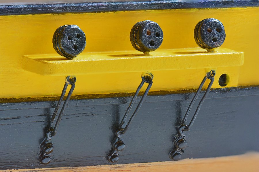
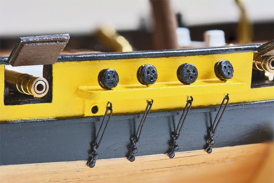
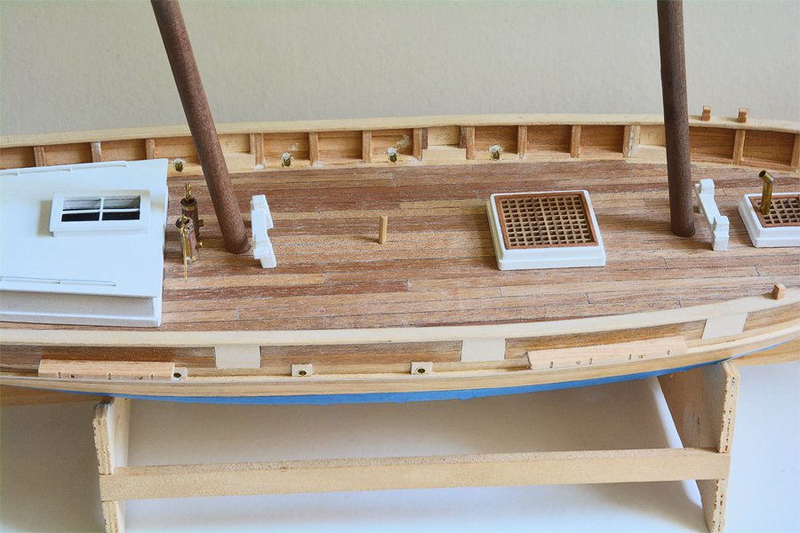
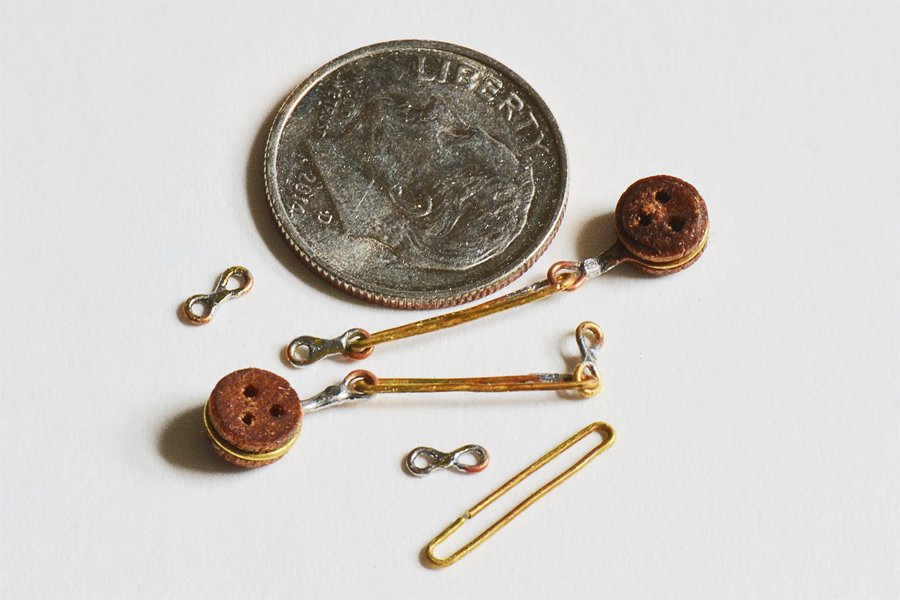
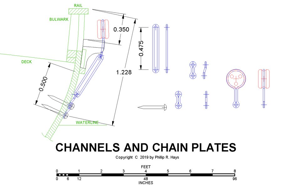
I have been working on the channels and chain plates, and the gun port lids/doors. Note: The pinrails should be installed before the channels. See post #166. The channels were fairly straight forward. They were fitted to the curvature of the hull and pinned with short brass nails into the bulwark supports. I examined drawings for 19 Baltimore schooners and revenue cutters and determined the spacings for shrouds at the deadeyes relative to length between perpendiculars. Deadeye spacing is related to mast height, and that is related to hull length. I had no data for mast heights so I used the hull length as a reference. For a 68 foot between perps ship the forward deadeyes were about 2 feet apart and the rear deadeyes averaged about 2 feet 2 inches. At 1:48 this is 0.5 inch for the four forward shrouds. For the three aft shrouds I placed the forward two at 0.5 inch and the spacing between the aft two at 0.6 inches. There will be ratlines between three of the forward shrouds and two of the aft shrouds, all spaced at two scale feet at the bottom. The blue painter's tape marks the waterline. Chainplate length was determined by the channel placement and the distance to the waterline. The deadeyes supplied with the kit were pretty good. I used the CAD program to work out the spacing and lengths of parts. I used 0.0185" brass wire to create the chain plates. Mondfeld's Historic Ship Models was my guide for the design of the chain plates. The only problem I had making them is that very small parts like these have an annoying habit of being someplace else other than where you expect them to be. I spent a fair amount of time retrieving them from the floor below my work table. I will attach them to the hull after it has been painted, The chain plates and deadeyes will be painted black - whenever the rains stop and we get some sunny dry weather!!! The gun port lids/doors were made of two pieces. The outer door was cut and shaped to fit in the port opening, resting against the rebate inside the port opening. Then the lids were sanded down to contour with the hull sides. A separate 0.040 inch piece was cut to fit into the port opening and then glued to the inside surface of the door lid. The doors fit snugly into the openings. The hinges for the gun port doors were a bit of a problem. Because the ports were open up to the top rail there was nothing on the hull planking to attach the hinges to. I had to attach them to the top rail - but how? I could have faked it and just glued the doors in the open or closed position, but I wanted working hinges. Eventually I came up with a plan. The hinges were made of three pieces of 1/16 inch OD brass tubing and a piece of 1/32 inch brass wire. Two 1/10 inch pieces of brass tube were soldered to the ends of a 0.525 inch long piece of brass wire, with a 0.225 inch piece of tubing in the middle. Two 0.050 inch wide pieces of 0.005 inch thick brass strip made the hinge straps. These were formed around a 1/32 inch drill bit and then the short end of the strip was tinned with solder. After these were placed around the hinge pins the short tinned end was reheated to solder it to the longer end of the strap. The cap rail is 1/16 inch thick. The 1/16inch diameter hinge tube is fitted into a recess carved into the edge of the rail, with the hinge straps glued to the gun port doors. For now the hinges are just fitted and not glued into place. First I need to paint the stripe between the top rail and the rub rail below the gun ports. I will fill the gaps around the hinges with Squadron white putty and sand everything smooth. Then the top rail, hinges and port doors will be painted black. I suppose the hinge straps should have bolts fastening them to the doors, but the smallest nails (7 mm) in my stock have 0.055 inch diameter heads - a bit wider than the 0.050 inch straps. I don't want to have to file down dozens of these tiny pieces. I'll look around to see if I can find pins/nails with 0.032 inch diameter heads, but I may have to be satisfied with no bolts in the straps. Personally, I think this hinge arrangement is a bit hokey, but it works. Unfortunately, 35 years ago when I built the hull I didn't plan ahead for the heights of the guns in carriages, size of the gun port openings and method of hinging the gun port lids. But, as I have said, this is a learning experience to prepare for building more accurate models. I am having fun learning about revenue cutters and solving problems building the model. EDIT: After gluing the hinges into cuts in the top rail I think it would be easier to install the hinges and fill the gaps with putty before gluing the hinge straps to the gun port covers. After the hinge glue was firmly set it would be easy to glue the straps to the port covers. Then the cover could be swung out and painted. EDIT: I have been studying how gun ports were arranged and operated on different ships in the early 1800s. I doubt that any real ship had gun port lids like I have modeled here. More likely the port lids would have been two parts. The top half would have been latched in place when the port was closed, and then lifted out and brought inboard when the port was opened. The lower half might have been hinged to swing down. The lids may or may not have had a circular opening in the center of the port to allow the gun barrel to stick out, with the lids closed around it.
-
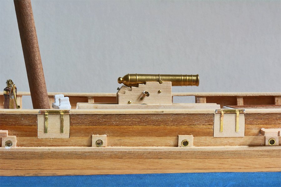
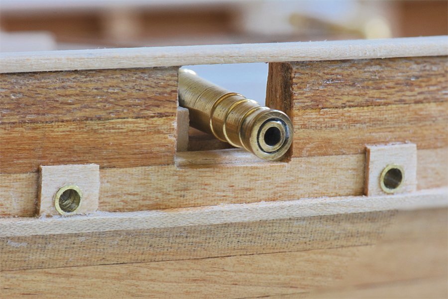
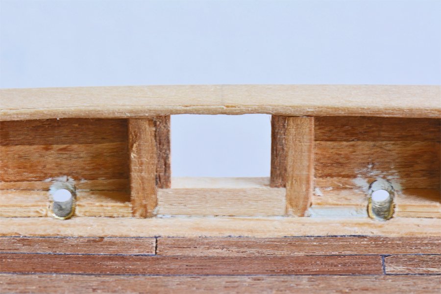
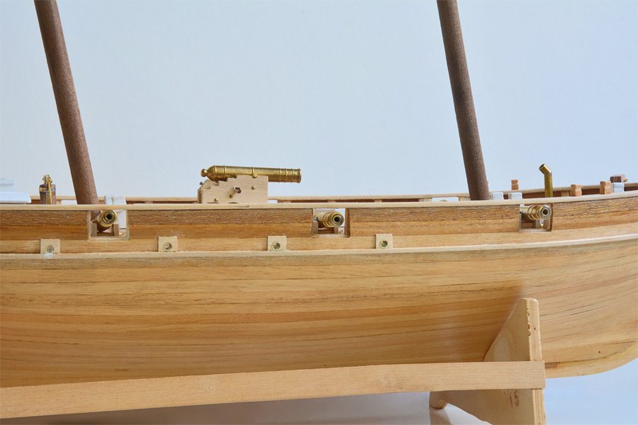
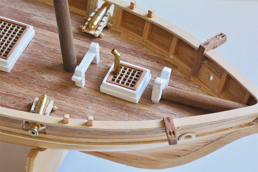
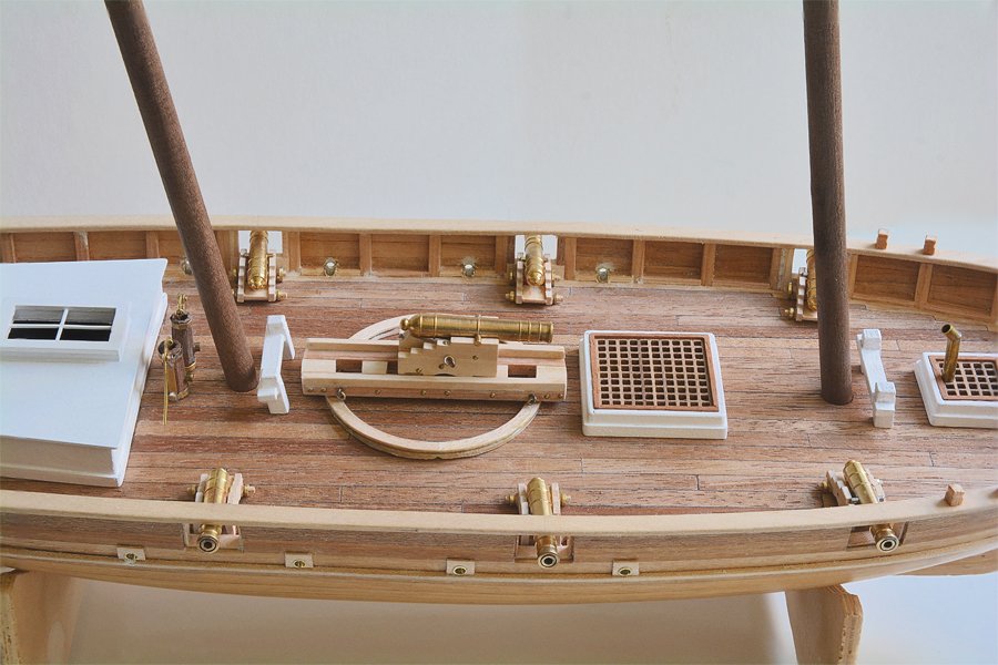
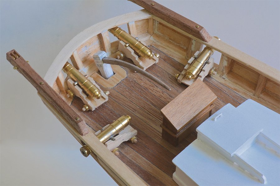
I have been working on the hull details to get it ready for painting. We have had some nice days lately, but I have spent most of them bike riding, hiking and picnicking. February was unusually rainy and cold so I had a bad case of cabin fever! However, I did get a chance to paint some of the deck fittings. The new work included cutting gun ports, adding the waterways and placing scuppers. The picture above shows the gun placements I decided upon. These positions allow for ample recoil without striking deck fittings, and there is no carriage gun aligned with the pivot gun. There are four ports along the sides and two stern ports. When I paint the hull the band below the top rail will be white and gun ports will be black. In addition to the four actual ports there will be another six false ports - just painted black rectangles the size of the real gun port lids. These photos show details of the gun port framing and scupper placement. The ports are lined to form a rebate for the port lids and the lower cill serves as the bumper for the gun carriage. There is no upper cill because the bulwarks are so low the top rail just clears the gun barrels when the guns are run out, as explained in an earlier post. The scuppers were a source of frustration. I screwed up royally. First, placing the cart before the horse, I glued the trim strip onto the hull at a distance below the top rail that "looked right" according to the kit plans. But when I drilled the holes for the scuppers the trim strip was higher than the edge of the deck, causing the scuppers to angle upward from inboard to outboard. That was bass-ackwards! Furthermore, I drilled 1/8" holes - 6 inches at 1:48 scale, and then realized that this looked too large (4 inch would have been better). The solution was to place a short piece of 1/8 inch diameter brass tube in the openings to get smaller diameter holes. But before doing that I pried the trim strip away from the hull and cut the scupper openings to angle downward through the waterways and overboard. All this required some careful drilling, filing and trimming with a 1/8 inch end mill bit to countersink the brass tubing so the bottom of the opening was at deck level. A 0.040 inch thick 1/4 inch square backing plate fit around the outer end of the tube. Fortunately, after the holes were elongated this piece covered the entire hole on the outside of the hull. On the inside the elongated hole above the brass tube was filled with Squadron white putty. You can see quite a few white putty patches in the pictures. Anywhere the fit between pieces is not perfect I rub in some putty. Finally, the 1/4 inch square backing plate was trimmed tangent to the bottom side of the brass tubing, and the trim strip was glued back in place below the scupper tubes. Well, this build was intended to be a learning exercise, so I guess I am learning things not to do next time! This picture shows the 6 pounder carriage guns and gun ports, and also shows how the pivot gun is mounted high to clear the bulwarks. When the pivot gun is run out port or starboard to the full limit of the slide, the end of the barrel is about 1 1/2 scale feet inboard the cap rail and about 1 1/2 feet above it. The blast from the gun would clear the rail without damaging it. Here are some pictures showing the deck details. The stern pictures show possible locations for the 6 pounder guns at the side and stern ports. The arrangement shown here would never have been used, but a gun could be hauled aft and fired outboard to get a four gun broadside. Or guns could be fired through the stern ports during a chase. In either case the quarter deck would be a bit crowded, especially with the rigging for the tiller and the main boom. The next step is to add the channels for standing rigging (The pinrails should be installed before the channels. See post #166). I saved that for last so they wouldn't be damaged with all the handling necessary to cut the gun ports and scuppers. Then everything will be painted with sanding sealer and any gaps sealed with putty. After that paint colors will be applied. I still haven't made up my mind what color the inside of the bulwarks will be. The gun carriages will be brown. I might even paint the area on the exterior between the cap rail and trim strip yellow, but I think that may have gone out of fashion by 1815, in favor of white.
-
Redrawing of Ship Plans using Fusion 360
Dr PR replied to Castos's topic in CAD and 3D Modelling/Drafting Plans with Software
Castos, The "rabbet" is a groove in the keel that the first plank (garboard strake) fits into. It looks to me that the 45 degree angles that you are referring to are the rabbet. Before going too far you must be certain that the vertical and horizontal lines are absolutely perpendicular. Just rotating to eliminate the "list" will not do this. If these lines are not "square" the hull will be warped. Are you planning to use the hull cross-sections to make a 3D model of the hull? Or do you plan to just cut out the bulkheads from your drawings? I would caution you that no matter how carefully you draw the hull lines they almost certainly will be a bit out of true. Some will be slightly "fat" and others "skinny." The result will be a wavy surface on a planked hull model. In some cases you can correct this by sanding down the high spots, but you risk sanding all the way through the planks. If you create a 3D CAD model of the hull using your section lines you can examine the rendered hull by rotating the view and changing the lighting angle. Imperfections will appear as a wavy surface. An even better way is to create horizontal (waterline) contours on the hull - just the lines of intersection between a horizontal plane and the hull surface at different elevations. Then hide the hull and examine the intersect lines by looking at them length wise (bow to stern, etc.). If any of the sections are too wide or too narrow it will cause the waterlines to be wavy instead of being smooth curves from bow to stern. Find the erroneous sections and correct the width. Create new waterlines and repeat the process until all are nice smooth curves. Then you will have a correct set of hull sections. This can be a time consuming process, but the result will be a good set of hull section lines that will produce a smoothly curved hull surface without ripples or low spots.