


Dr PR
-
Posts
1,491 -
Joined
-
Last visited
Content Type
Profiles
Forums
Gallery
Events
Everything posted by Dr PR
-
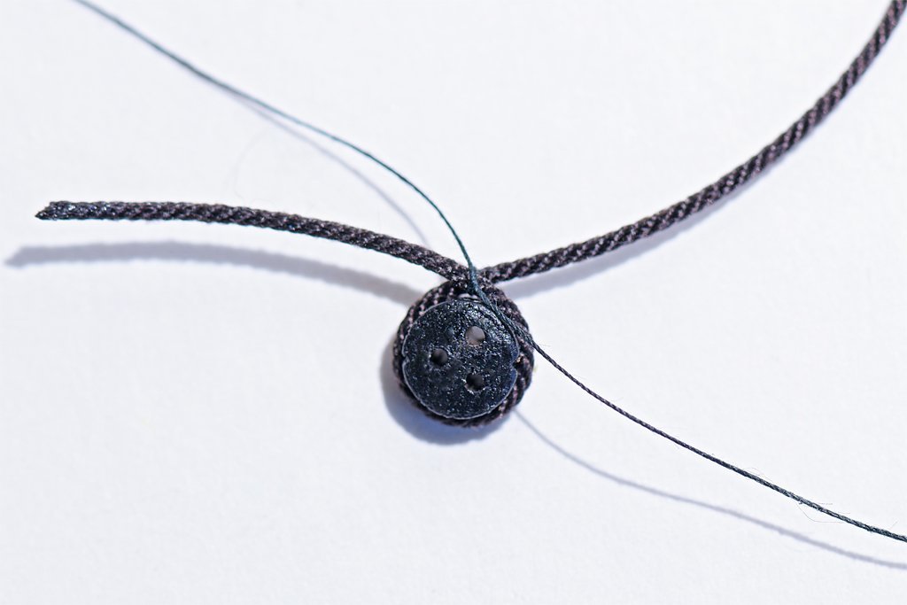
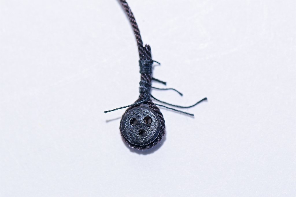
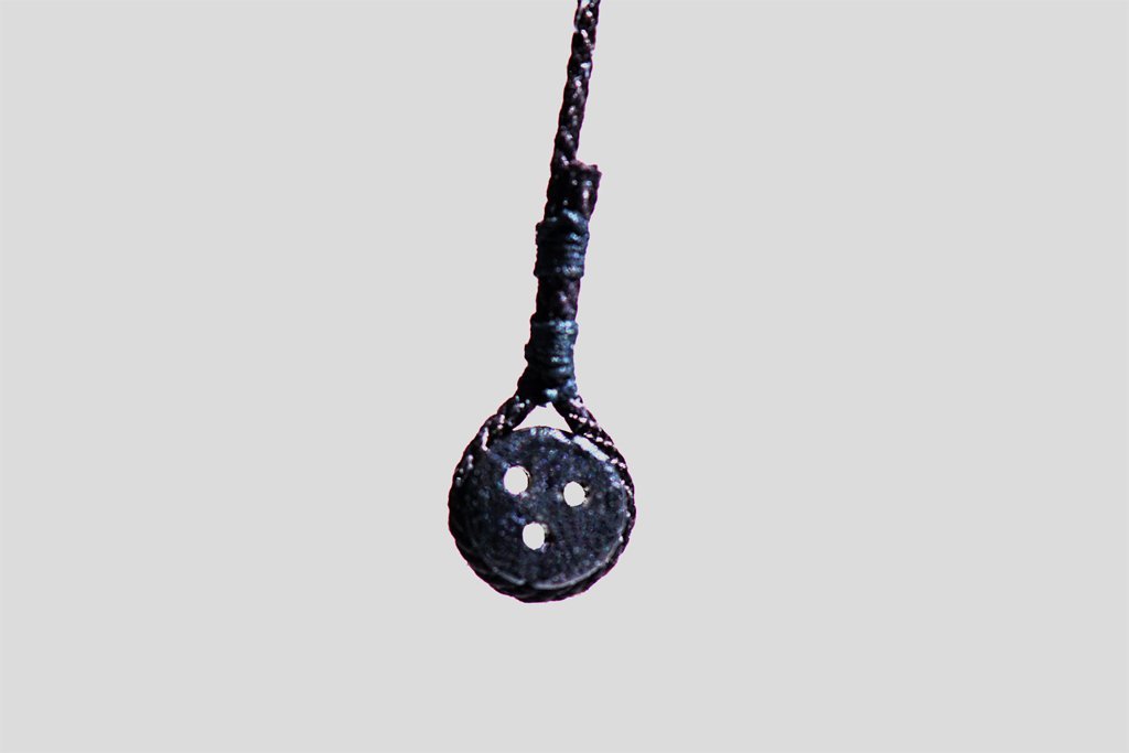
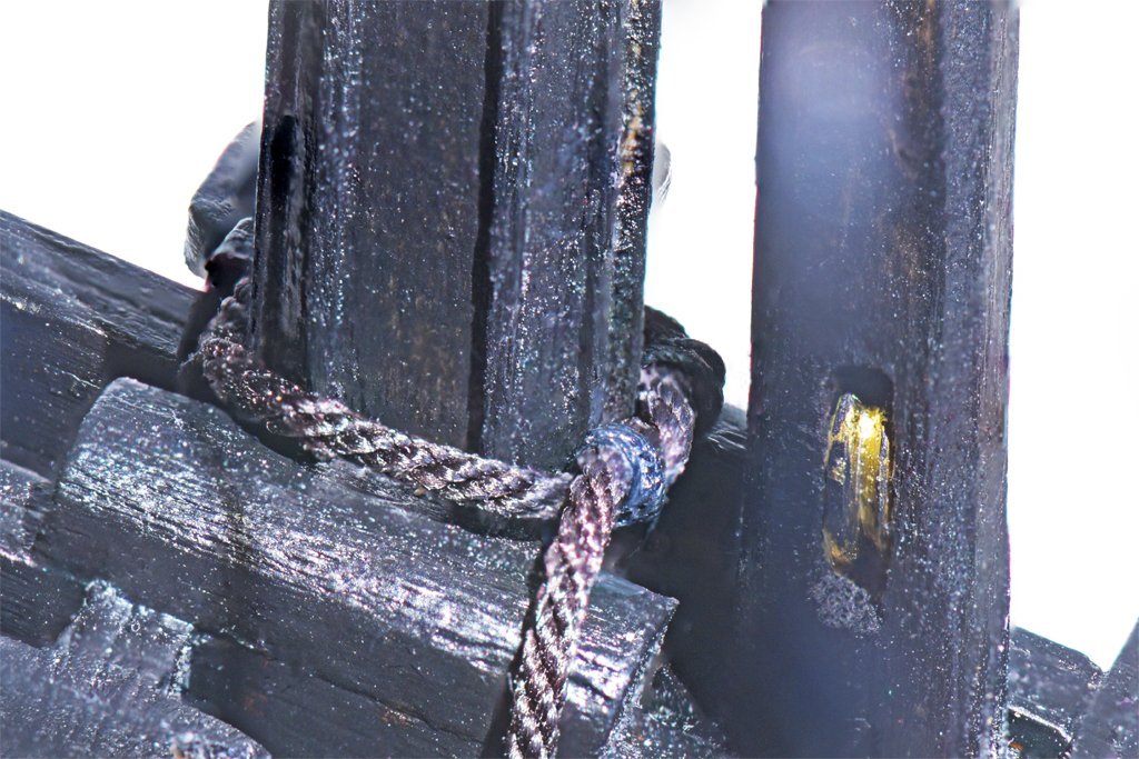
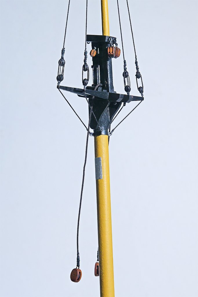
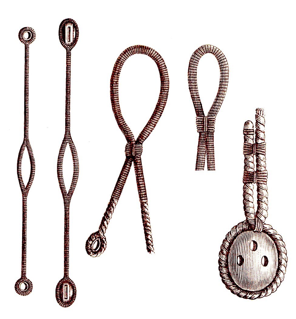
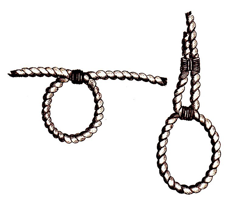
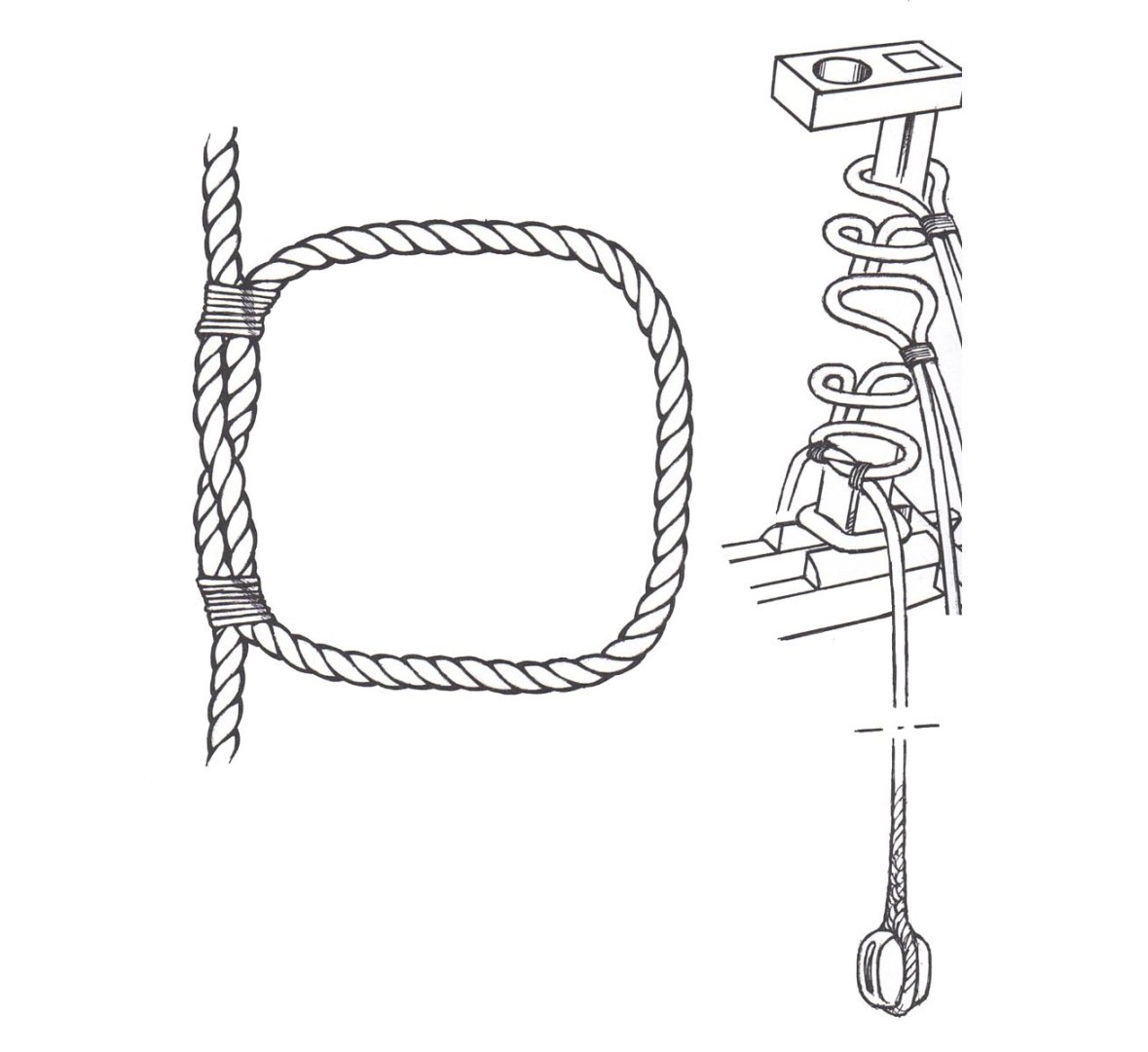
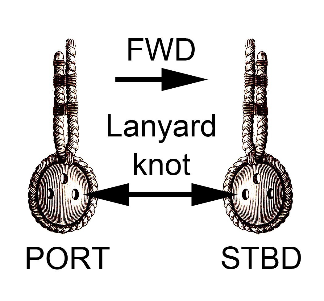
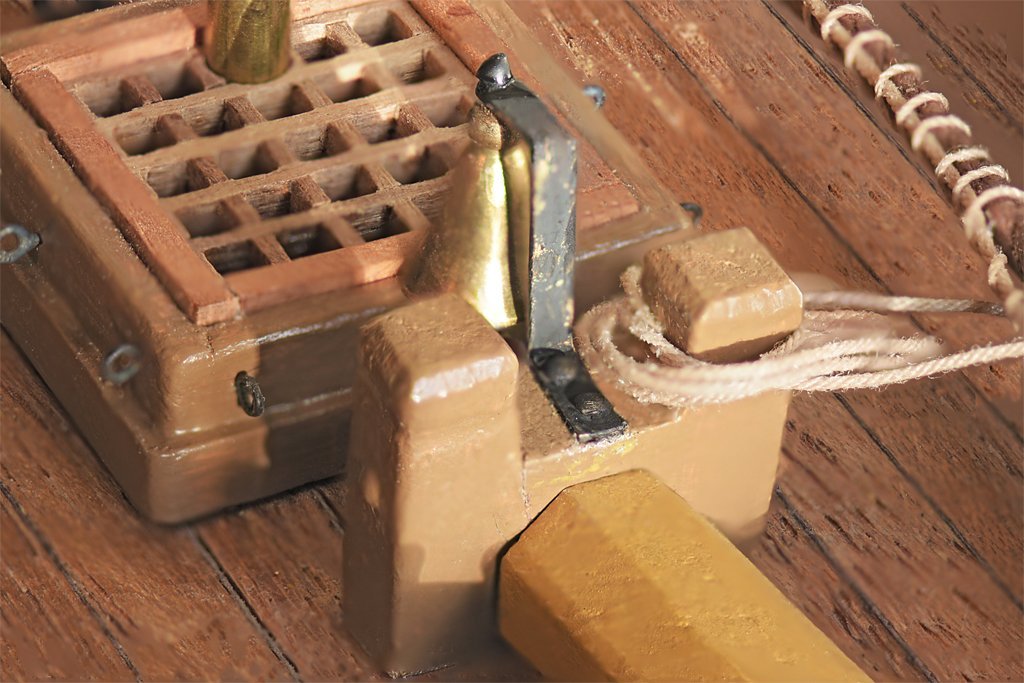
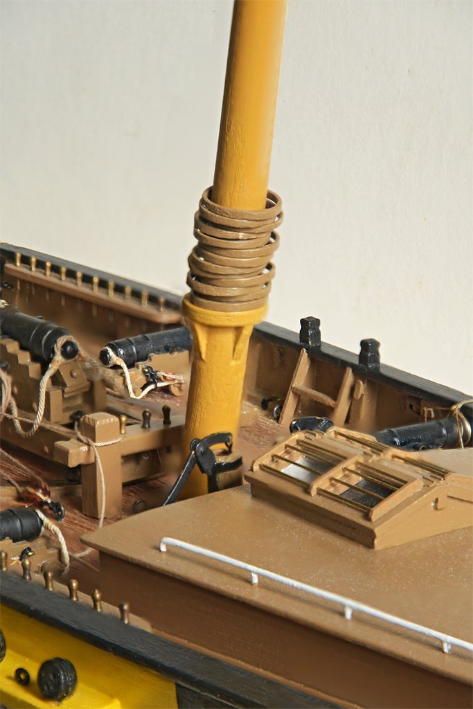
 I have started on the foremast shrouds. The first problem I encountered was how to rig the mast tackle. On larger vessels the burtoning rig was often attached to the topmast hounds, but on smaller vessels the tackle was on the lower mast top. Darcy Lever's The Young Sea Officer's Sheet Anchor (left) shows several ways to rig the tackle. The two examples on the left (naval and merchant versions) show a cut splice around the mast. The center drawing shows the tackle pendant as the extension of one of the odd number shrouds. Petersson's Rigging Period Fore and Aft Craft (right) shows another arrangement for the mast tackle. Lees' Masting and Rigging of English Ships of War, Marquardt's The Global Schooner and zu Mondfeld's Historic Ship Models all repeat versions of these designs. All say that warships had the tackle pendants individually spliced around the mast heads, but merchantmen tackle pendants often used the cut splice or were part of an odd shroud. The arrangement Petersson shows is also mentioned. But none agree on the order the shrouds and tackles are placed on the masts. They all say the starboard forward shroud pair is placed first, and then the port forward shroud pair. But some imply that the mast tackle is put on before the shrouds, and others say they are the last to go on! I have decided to use the arrangement shown in Petersson, and to put it on first. In this way the loop of rope around the mast will also serve as a "cushion" for the shroud ropes, and the tackle pendant will descend inboard of the shrouds. This is important because the tackle pendants and the associated runner and luff tackle rigs will be inboard of the shrouds and rat lines, and hook onto eyes in the channels. I placed one twist of the rope around itself in front of the mast and added seizing on both sides of the mast. In all cases I apply a drop of white glue (school glue) to the seizing to secure the fastening. I use the ordinary white glue because it drys clear and virtually invisible. It can also be loosened with a drop of water to untie the seizing. The tackle pendants are about 1/3 of the lower mast length between the deck (partners) and the hounds (trestletrees). This length varied with the period, and was sometimes half the mast length. The deadeyes are rigged as shown in Lever's drawing at the top of the page at upper left. Several references were specific in saying the deadeyes were fastened to the shrouds with a throat seizing, as shown at left in this drawing from Lever, but with two seizings above the loop. They also specify this type of seizing for use on stays and other parts of the standing rigging - but don't say why. I have noticed that simple round seizing (like the upper seizing in this drawing) but without the lower seizing around the loop) can slip, allowing the end of the rope to slide down and out of the seizing. This has happened to me a couple of times after I have finished the round seizing but didn't allow enough time for the glue to dry before putting strain on the lines. But with the knot around the loop in the throat seizing this does not happen. This may be the "accurate" way to fasten deadeyes to the shrouds, but it is a pain in the posterior to tie that first seizing around the loop with the deadeye in the way! It would be a lot easier to just use the round seizing! There is another detail to be noted on setting up the shrouds. They were made differently for cable laid rope (left hand spiral) and hawser laid rope (right hand spiral). Lees says English men of war always used cable laid rope for shrouds, so American vessels probably followed suit. Coincidentally, the 0.035 inch brown rope from Syren that I am using is cable laid (not all Syren rope is cable laid). With cable laid shrouds the end of the shroud rope is on the aft side of the deadeye on the port side of the ship, and on the forward side of the deadeye on the starboard side of the ship. In this image you see the deadeyes from the starboard outboard view, so the inboard side of the port deadeye and the outboard side of the starboard deadeye are seen. When the lanyards are rigged the standing end has a knot to prevent it from pulling through the hole in the deadeye. The lanyard is first pulled through from the inboard side of the deadeye through the hole shown in the drawing (forward on the port side and aft on the starboard side). After the lanyard is run through all the holes in the deadeyes the loose end is fed through the gap between the upper deadeye and the rope loop (not shown in the drawing) then round the shrouds and back under itself. It is wound around the ropes a few times and then seized to the shroud ropes. It will take me a while to finish rigging the shrouds to the two masts.
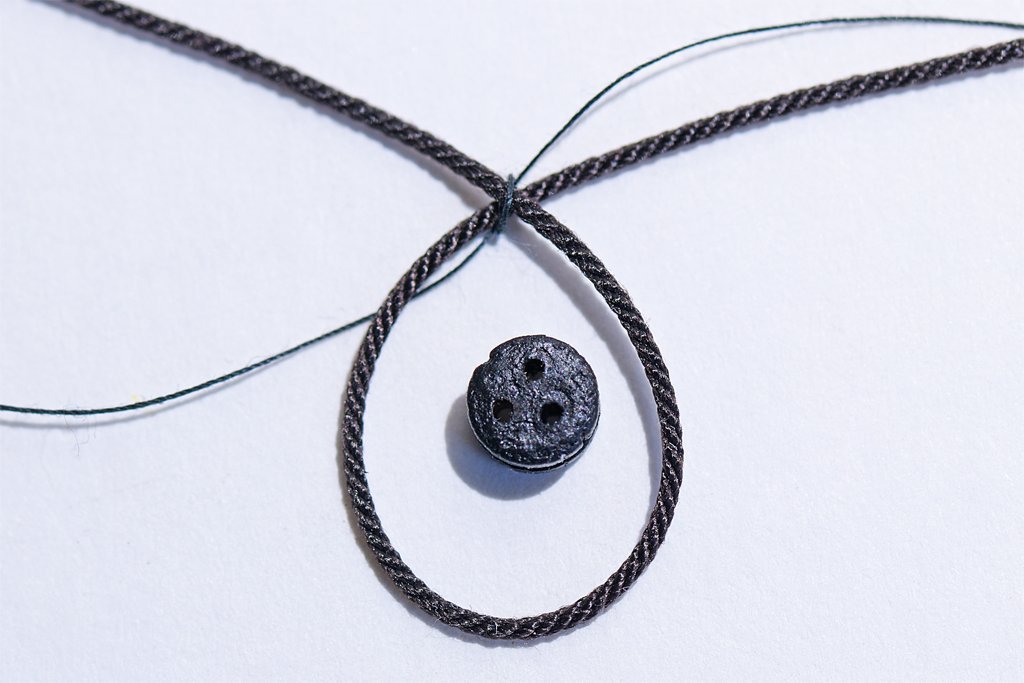

-
Kieth, I like the way you think things through and plan carefully. OK, so the first effort at the stern tube was a bit off, but if you weren't being so thorough checking and rechecking you wouldn't have noticed - and neither would anyone else! I enjoy following your work, and always look forward to learning from you new and better ways to do things.
-
I hope you start a thread for the Achilles.
-
You can try to make your own stepped mandrels using square metal tubing. McMaster-Carr has a wide assortment of metals and tubing sizes where each size slip fits into the next larger size. For example they have brass tubing stepped in 1/32 inch increments: https://www.mcmaster.com/products/rectangular-tubing/material~260-brass/ By getting and assortment of sizes, slipping them inside each other and soldering them together you can make a square mandrel like you are looking for.
-
In my early planked hulls I also had problems with the wood shrinking and swelling, opening cracks in the hulls even after they had been sealed and painted. About 35 years ago I started using a thin clear two part epoxy paint to seal the interior of the hulls. This paint is used by airplane modelers to seal wooden engine mounts so they don't soak up fuel. The paint filled in any cracks between planks and soaked into the planking and bulkheads/frames. After it hardened the planking was very solid. After 35 years of long wet winters and hot dry summers there have been no cracks opening in the hulls.
-
Yves, You are wasting your time asking about the match. We have all asked Valeriy the same thing and he won't tell us his source! He claims it is an ordinary match! If so, it is the only part of his builds that isn't extraordinary!!
-
I have used thin aircraft plywood for small wooden parts like the boom jaws. Plywood is much less likely to break while working on the parts. They were cut out to rough shape and then filed to the final shape: https://modelshipworld.com/topic/19611-albatros-by-dr-pr-mantua-scale-148-revenue-cutter-kitbash-about-1815/?do=findComment&comment=1012539 I am modeling an early 1800s vessel so I used metal bands around the boom jaws: https://modelshipworld.com/topic/19611-albatros-by-dr-pr-mantua-scale-148-revenue-cutter-kitbash-about-1815/?do=findComment&comment=1012900 Later vessels used bolts instead of the metal bands. I don;t know what the Bowdoin used.
-
Rich, Thanks! This build has been a learning experience, and I have had to change my plans several times as I discover new things. But I am sure the day after I think it is "finished" I will see something I did wrong!
-
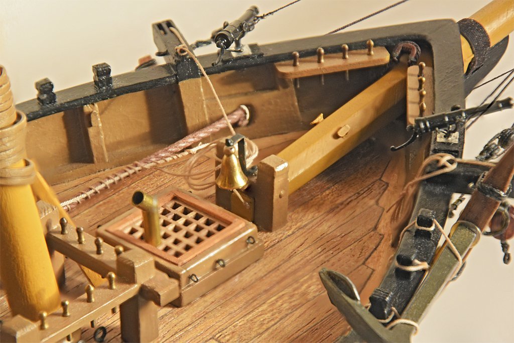
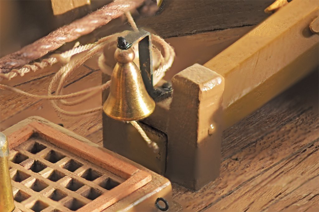
I have been reviewing all of the rigging and the belaying plan and making last minute additions and adjustments. I discovered I have overlooked the main sail tack, and a place to belay it. I did have the fore sail tack attached to a luff tackle to a ringbolt at the base of the fore mast. But I had overlooked the tack for the main sail, and this caused a problem. The bell was in the way! The tack of the gaff sail was sometimes attached to a luff tackle that hooked to a ring bolt at the base of the main mast. This allowed the tack to be pulled down to stretch the luff edge of the sail taut. But sometimes it was simply strapped to a ringbolt on the boom jaws. In this case just the weight of the boom might hold the sail down, but I have seen a (rare) reference to a tackle to haul the boom jaws down against the boom rest. In either case, the tackle must run down the aft side of the mast to a ring bolt on deck, and I had placed the ship's bell directly in the path of the tackle. I had wanted to place the bell on the fo'c'sle because I have read that by the late 1700s this was where bells were being located. My earlier experiments with a belfry were an unsuccessful attempt to do this. I found some photos and drawings of bell attachments on schooners of the late 1700s through the 1900s and smaller vessels often had a simple bracket for the bell, and it was often attached to knight heads or windlass supports. I don't want the bell rising high where it might interfere with the forestay sail so I devised a simple bracket to mount the bell on the bitts securing the base of the bowsprit. I did not intentionally "weather" the finish on the bell bracket. I have had frequent problems getting the blackening (Birchwood Casey Brass Black) to produce an even finish. The metal was washed with water and dish soap, then thoroughly rinsed. Then it was washed in acetone and then isopropanol, and the parts left for the alcohol to evaporate. After this it was left in warm vinegar for about ten minutes and washed in water. Then I actually left the bracket in the blackening solution for twice the time (10 minutes) I normally use. As before the results are blotchy. But it will do. Now the aft side of the main mast is clear to allow the run of the main sail tack tackle (if I install one) or any other line that may pass there in the future! I think I now have a complete rigging and belaying plan (but I have thought this before) so now maybe I can step the masts and start rigging!
-
403. That’s an error. Your client does not have permission to get URL /books/content?req=AKW5QafzDR4HEhnhr6lb_WUGy2LlWkQoiX5Srp-3LuF3qNXe53J3svidQYaojQns-MhC_ey3cHVH7zlcLCPnX88-qihqU4fGsbgruf7bUhgj6f08At29jbvwhVPJJb5IVcE90YxqYJvLQey3GuJ0owS30HpNgkZOoCEBcmotF8SbCW2vqkaGFrWGLtPvI1qWdx8j0m9faEd9uuFztrKAKln-s5bOFXfGhm2UzTTir09bZlgkLh-iD4bzq406IU5twzcA-iydFf99N14_4KWYFfPZ39NeEsyMaKqnUHAdFAvxzYjfNLYi_6s from this server. That’s all we know. Isn't technology great!
-
White lettering decals..How?
Dr PR replied to wmherbert's topic in Painting, finishing and weathering products and techniques
Here are some words of caution about do it yourself decals. I have prepared quite a few over the years - and white has always been a problem! There are decal papers for ink jet printers and laser printers. Ink Jet printers: The inks are water soluble, and that can be a problem with water slide decals! You may need to coat the printed decal with a clear finish before using. Laser printers: These can produce decals that do not have water soluble inks and do not have to be coated before using. CAUTION CAUTION CAUTION! Laser printers have a heated "fuser" that literally melts the toners (ink powders) onto the paper. Some printers caution about using any paper with a clear shiny coating (glossy photo papers, decal papers, etc.). The fuser may melt the coating, DESTROYING THE FUSER! I speak from experience! I used a glossy "laser printer" photo paper on a very nice Samsung laser printer and afterward it wouldn't print correctly. The fuser had glossy goop on it that prevented it from picking up the toner. Then I learned that printer didn't have a replaceable fuser (every other laser printer I have owned did have a user replaceable fuser). The entire $600 printer was junk. I replaced it with a Brother "laser" printer that has a replaceable fuser. But it really isn't a laser printer - it has a 600 dpi LED bar to expose the image onto the fuser. It has a VERY hot fuser that melts the glue on envelopes! I contacted Brother about whether it could be used with laser decal papers and the advice was NO! No glossy or non-paper materials at all. I have printed decals on other laser printers in the past with no problem. Recently I printed some color decals at the nearby FedEx Office Store. They used a laser printer that was OK for decals. However, I was trying to match the colors on an object, and the FedEx printer produced different colors from what I get printing draft test sheets at home on paper. I eventually found RGB colors that would print the desired colors on the FedEx printer. Check your printer's manual to see what materials they recommend (or don't) for printing on. -
Another source of small "nails" or "rivets" is jewelry making supplies at a crafts store. I noticed some long brass pins with flat heads at Michaels. However, the heads were 1/16 inch (1.5 mm) or larger.
-
Tiny Spar on 17th Century English Yacht
Dr PR replied to catopower's topic in Masting, rigging and sails
Sailing Ships, Bjorn Landstrom, Doubleday & Co., Garden City, New York, 1969, page 156. It is just a small picture. -
What glue to use
Dr PR replied to David Enghauser's topic in Building, Framing, Planking and plating a ships hull and deck
I don't especially care for "super glue" (cyanoacrylate). It sets too quickly to allow for adjustments. CA doesn't adhere well to metals. It leaves a permanent blemish (shiny spot that won't take stains) on wood surfaces so be careful using it on surfaces that will not be painted. I have used Sig-Bond aliphatic resin for gluing wood. It does take a while to set up, but makes a strong bond to porous materials. My favorite glue is Duco Cement (nitrocellulose in acetone). I have been using this glue for perhaps 70 years. It sets quickly (about 20 seconds) but gives you time to adjust things. It hardens fully over night. It adheres to wood, glass, plastic and metals. But the best "glue" for non-porous materials like metals and glass is epoxy. It also works well for porous materials like wood. In fact, it is probably the best glue for anything, but is not as convenient (has to be mixed immediately before use) as other glues. -
White lettering decals..How?
Dr PR replied to wmherbert's topic in Painting, finishing and weathering products and techniques
Here is another option using rub-on letters as stencils. 1. Get some rub-on letters in the desired font and size. Color doesn't matter. 2. Paint an area with the desired letter color (white for example). Let the paint dry thoroughly. 3. Rub on the letters, placing them carefully, of course. 4. Paint over it all with the background color (black, for example). 5. Let the paint dry. 6. Use tape to remove the rub-on letters. Now you have white letters on the black background (or whatever colors you use). There is no decal film around the letters, and they are only as thick as a layer of paint. The lettering will not yellow as decals do over time. I have been using this process for many years, and other that getting the rub-on letters aligned properly it is pretty simple. -
Tiny Spar on 17th Century English Yacht
Dr PR replied to catopower's topic in Masting, rigging and sails
Clare, I have seen this method of strengthening the peak of sails a number of times. I think a short spar like this that is attached to the peak of a sail is called a "club" but I am not certain. The Dutch used a very short spar like this at the peak/head of sails in the 1600s on small vessels (Sailing Ships, Bjorn Landstrom, Doubleday & Co., Garden City, New York, 1969, page 156). This later grew into the common gaff. So if it is on a sail rigged aft of a mast perhaps it should be called a gaff. If rigged before the mast as in your picture I guess it is just a "spar" or perhaps a "club." Somewhere I have a reference that shows how to make these. The sail is laced to the club/spar. The halliard attaches to the spar. I don't know if it matters how, but in your picture it looks like the halliard block is riding on a line attached to the ends of the spar. It may be securely attached to the line at its center, or just sliding along the line. I can't tell from the picture. But I see no reason when the halliard couldn't be attached directly to the center of the spar. Since this idea seems to date back many centuries it is possible it has been used in many rigs in many places. I am sure I have seen it in photos of modern vessels. What is the name and period/date of the English yacht in the photo? The Dutch were using something like this on their yachts in the 1600s and 1700s. The English copied a lot of the Dutch ideas. -
Travis, You have a decision to make. You are working on the beginner's three boat series where you will learn about wood, paints, tools and the basic practice of ship model building. Good for you. You are off to a good start. But what then? You have three choices: 1. Ship modeling just isn't your "thing." Give it up and do something else. 2. If you enjoy ship modeling pick another kit a bit more challenging than the last, a brig, schooner or fishing boat, and build it just for fun according to the supplied plans. 3. Get really deep into the hobby and research every part of your next build to make it as historically accurate as possible. It may be a kit or a scratch build, but the real fun is in the research. Most of us repeat step 2 several times before we plunge into step 3.
-
USS Constitution by mtbediz - 1:76
Dr PR replied to mtbediz's topic in - Build logs for subjects built 1751 - 1800
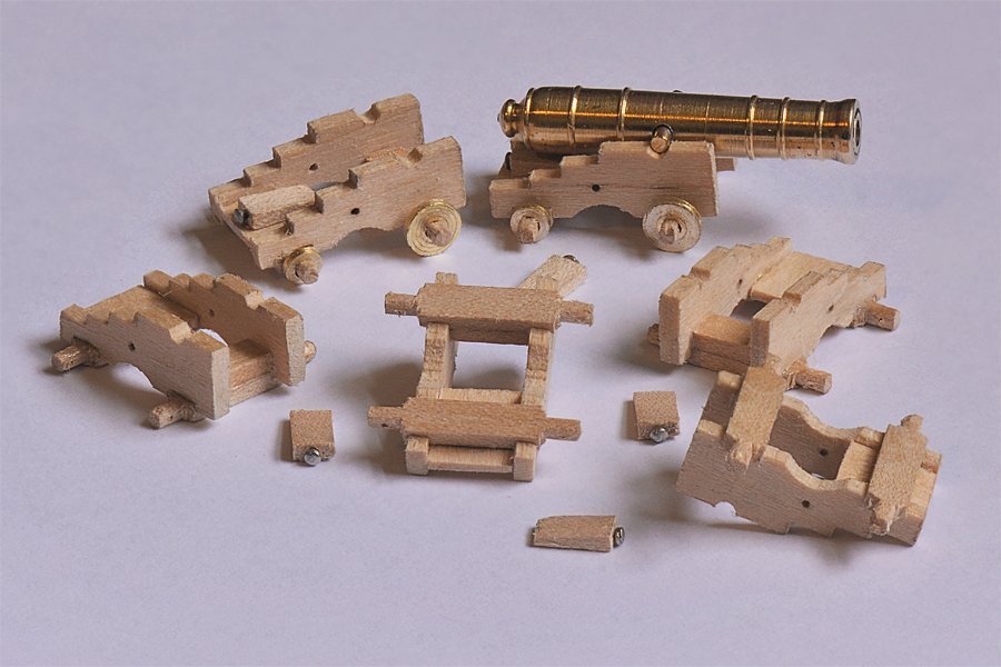
Mustafa, Nice work! The Constitution has a special place in the hearts of us US Navy folk. I too have been lusting after the Proxon MF70! There is a trick I use to simplify the making of many identical gun carriage sides (cheeks) or any other similar parts without using a table saw (I don't have a table saw!). I cut a long piece of wood to the right height and thickness of the carriage sides. Then I cut off pieces that are a bit longer than the carriage sides. I line up all of these rectangular pieces side by side and clamp them together. Then I file the ends flat and glue a strip of wood across each end. This produces a single "block" of many identical side pieces that can be milled as a single piece. Then I milled the block, cutting each feature of the carriage sides in all the pieces in a single pass, just as you did with your milling machine. After all the cuts were made I milled off the glued-on end pieces to free up all the individual carriage sides. This also cut the side pieces to the correct length. This produces carriage sides with the wood grain running the length of the pieces instead of across the parts. You can see a stack of side pieces as they came out of the mill (after the glued-on end pieces were cut away) at the upper left of the left photo, and some assembled carriages in the right photo.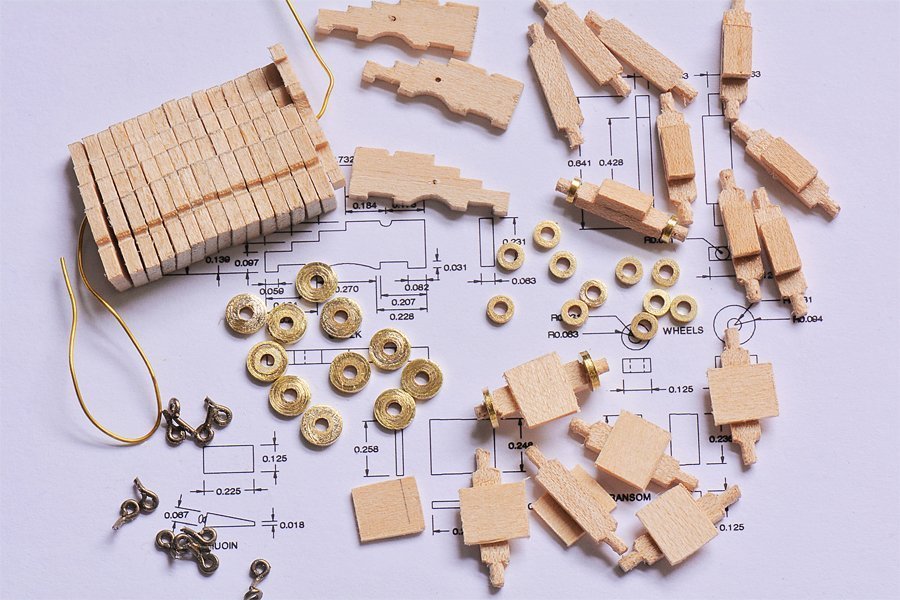
-
Allan, Good point! Lines couldn't belay to pins unless there were pins to belay to! Before pinrails, fife rails and such, lines were belayed to kevels (cavels), cleats, bitts, knight heads, timberheads and such. Whatever was available it seems. Over the last few hundred years of sail the ships became larger, with more masts and more sails, all with more and more complex rigging. I suspect fife rails and pin rails came into use as a necessity to deal with the ever growing number of lines that had to be belayed, and organizing them in a rational way. There is another exception to the general "rules" I mentioned above. On some vessels some lines, like halliards and bowlines, were run forward of the mast, and the higher they originated the farther forward they were belayed. Again, it was whatever worked to avoid fouling lines.
-
Brig USS Enterprise 1799 info gathering
Dr PR replied to CharlieZardoz's topic in Nautical/Naval History
Thanks. Looks like the search for the Holy Grail will have to continue! -
Nissan Fairlady 240Z by kpnuts - FINISHED - Tamiya - 1/12
Dr PR replied to kpnuts's topic in Non-ship/categorised builds
This brings back memories! I saw the original "Fairladys" when I was stationed in Japan in the late '60s and early '70s. But that name was too tame for the American market where it would compete with Camaros, Trans Ams, Chargers and Mustangs, so the marketing morons coined the much more macho "240Z" name for imports into the states. After all, would James Bond be seen driving a "Fairlady?" -
Bob, I discovered this fairly cheap source of good quality wood (along with bamboo barbecue skewers) long ago. Other useful sources of supplies are paint mixer sticks, roofing gutter flashing, jewelry supplies, carpentry wedges and even bundles of fire starters! Walk through a crafts store or hardware store with an open mind and you can find all sorts of materials useful for our hobbies.
-
Allan, I am fairly new to the study of sailing ship rigging, having started on a topsail schooner about five years ago. But one thing I have discovered is that it is probable that no two ships were ever rigged the same way! So Lees (Lever, Marquardt, zu Mondfeld, Chapelle, McGregor, Peterson, Underhill, Biddlecomb, Steel ...) may show the way a particular ship was rigged, but that doesn't mean every ship was rigged that way! There is only one rule that I have discerned that applies to every ship - a line must not foul other lines, spars, masts, etc., and when possible it should be routed so it doesn't chafe against other parts. Given this rule you have to attach lines and blocks wherever necessary and find a place to belay them to clear as much of the other rigging as possible. I suspect it was the Captain, Mate or Bosun who decided how things were rigged on their ships, and that might change with time and experience. There are some general trends for belaying that I have found: 1. Lines that originate lower down in the rigging generally belay forward on pin rails, fife rails and cleats. Lines from higher points belay farther aft. 2. Lines descending from near the mast belay near the bottom of the mast (partners). Lines descending from yard arms belay along the bulwarks or deck edges. 3. An exception to 2 is that lines from very high in the rigging, whether from yard arms or from near the mast, may belay along the bulwarks or near deck edges. The prime rule is that lines must not foul other lines. They may be led through fairleads on crosstrees or the bowsprit, through thimbles/trucks on shrouds, or running blocks attached where necessary to lead them around obstacles. How all of this is accomplished depends upon the configuration of the masts, spars and rigging on the particular vessel. For example, I have found three different ways the fore course (spreader) yard braces were routed on topsail schooners, and there may well be other ways. Perhaps the most frustrating thing I have encountered is that almost every "authority" I have read that describes ship's rigging says for every line that it was "belayed below" or "on deck." Very few books show where the lines were belayed "below." I eventually figured out that this is because no two ships were rigged the same. So unless you have the original rigging and belaying plan for a particular ship you are pretty much on your own to figure it out for yourself!
-
Brig USS Enterprise 1799 info gathering
Dr PR replied to CharlieZardoz's topic in Nautical/Naval History
Has anything come of the drawing Geoffrey Footner found in the archives of the Arsenal of Venice believed to of Enterprize? Is is actually a drawing of that vessel?


