


Dr PR
-
Posts
2,406 -
Joined
-
Last visited
Content Type
Profiles
Forums
Gallery
Events
Everything posted by Dr PR
-
Here are a couple of comments related to these discussions. 1. I just had a great Christmas dinner that included barbecue ribs cooked up by my significant other's youngest son. He took home economics in school and learned to cook. He is a really good cook! So I guess I can thank his home ec teacher in part for the great ribs!. 2. I have several thousand blueprints for the Cleveland class cruisers on microfilm. I have scanned and digitized hundreds of them for making my USS Oklahoma City model. I scanned at the equivalent of about 9000 dpi on the film. This produced clear images of even the smallest lettering. Each drawing has a title box with the draftsman's initials and I soon learned to recognize the draftsman by looking at the lettering. And different people had different ways to create drawings. The scanned images are so good that I can see the tiny pencil dots that were used for centers of circles and to evenly space guide lines for the text. I love looking at these blueprints and learning how the ships were built. However, some of the lettering is very poorly done. One fellow made 3 and 5 almost identical, so if the microfilm image isn't really clear you can't tell these numbers apart. And some drawings have long sequences of comments documenting changes. These were made my multiple people and the lettering quality varies from good to horrible. Some of the draftsmen were better artists than others! **** Now I take exception to the comments that all CAD drawings are alike or not artistic. Like the paper drawings, it depends upon the draftsman. At least all of the text is legible! But different people make CAD drawings in different ways. I have worked with engineers who did sloppy work, on paper and in CAD. And I have worked with some fellows who truly were CAD artists, who took pride in their work and added all the little details that distinguish a nice blueprint from a bad one. Again, everyone has their own opinion. I have worked extensively with paper drafting and CAD. I appreciate nice work done either way.
-

Hull Planking Question
Dr PR replied to tomsimon's topic in Building, Framing, Planking and plating a ships hull and deck
Bob, Thanks for the information about wood shrinkage and expansion with humidity. I have long been aware of the problems with expansion/contraction of metal and plastic with temperature change, and the large differences of thermal coefficient of expansion for these materials. I hadn't given much thought to wood, except that it has a relatively low thermal coefficient of expansion and the problems this can cause in constructions with wood, plastic and metal. I have three plank on bulkhead hulls that date back to the 60s through 80s. All are single plank hulls. These have been in the western Oregon environment where we have humidity swings several times a year between 20% and 100% (normally 35% to 70%). Winters are especially damp. It can start raining in late October and not stop until May. Then we may have no rain from May to October. I would think this would make a good test of the effects of humidity swings on model hulls. The first two hulls (14" to 15" long, built in 1969) had planks glued (or nailed) to bulkheads with no glue between planks. As you noted, expansion/contraction was localized. Both of these hulls have pronounced cracks between some of the planks. The ordinary lacquer or enamel paint applied to the exterior was not sufficient to prevent gaps from appearing. The third hull (18" long, built in 1985) has no cracks after 35 years. The inside was painted with the epoxy paint as described in my earlier post (several coats until the wood absorbed no more). See the link to my Mantua Albatros build in the footer of this post. I think the reason it has not cracked is pretty simple. Every piece soaked up the epoxy so the bonds penetrate into the wood. Each plank is bonded tightly to the bulkheads, so the planks cannot move. Each plank is bonded tightly to its neighbors, making it difficult for gaps to appear. I would say 35 years in this environment without cracks is a pretty good test of the process. One thing that may have contributed to the stability of this hull is that it probably was built in the winter (not many good days for hiking) , with relatively high humidity. So the planks may have been expanded when they were glued together. For what it is worth, all three hulls were from kits, and the wood was whatever was thrown into the box. Back in the 60s to 80s I doubt if anyone gave any thought to how the grain ran in the wood. The plank dimensions of the 1980s kit varied quite a bit, especially in thickness! These were fairly small hulls. If I was building a 3-4 foot hull I would certainly give some thought to wood expansion and contraction. -
As a child I took 9 years of art classes outside the regular school system. In these I learned about perspective, viewpoints and such, all for the purpose of making pretty pictures - what is called "art." But I have always had the ability to create 3D perspective drawings on paper. For me it was fun. I made straight As in geometry in junior high school - it all came naturally to me. In college my freshman roommate was majoring in engineering, and he had mechanical drawing classes. Like so many people he had no concept of perspective. I would look at the three-view (front, side, top) 2D images and just draw the 3D perspective for him by hand. Years later I learned how to use mechanical drawing tools for work on drafting boards. I read through some drafting books and it was all pretty obvious. Again, it came naturally. I have always loved to draw (and still do), whether it is an artistic picture, a botanical drawing or an engineering plan for a house or machined part. Then along came CAD in the late 1980s. We used AutoCRUD at first and it was awful! What we called a VERY user unfriendly program. One day one of the engineers tried a CAD program called ProDesign. One look at the user interface (the best I have ever seen on any program) and AutoCRUD went into the trash. We have used the same program ever since, although the program has changed hands from company to company several times. Today DesignCAD is considered to be a "hobby" program, and it lacks some of the bells and whistles of more expensive programs. But it is still a very capable 2D and 3D drawing program. Considering it costs about $100 with free bug fixes and technical support, and it has a great free user Forum where you can ask experienced users how to do things and solve problems, it is a tremendous bargain. Some of the "professional" CAD programs I have also used ($15,000 per seat with $1500 per year fees for technical support and access to user forums) can't do some of the things the $100 DesignCAD can do! So I have experience from both sides. I still do preliminary "back of the napkin" sketches on paper with pencil. I love working with wood and building wood ship models. But the ability to rework a drawing in CAD without messy erasers and whiteout, or just redrawing the entire thing as you do on paper makes CAD the ONLY way to go for a large complex drawing. If you have any doubts, just ask yourself how you rescale the size of text on a paper drawing that was created with a Leroy set? You start over and create a new drawing sheet - all of it. In CAD you click on the text and say I want it 25% larger, and while we are at it let's use a different font. And I can take an old CAD drawing and modify it to create new things without starting over from scratch. But is it art, and can you use it for ship modeling? And do you need 3D? First, some people will never understand 3D drawing. One of their greatest handicaps has been familiarity with 2D drawing techniques, and even 2D CAD. In 2D you draw an image of something in the real world. In 3D you create an entirely new world. It is not drawing, drafting or anything like it - it is modeling, as if you were creating something out of modeling clay, only it is virtual clay. Very few 2D drawing techniques apply to 3D, and 3D CAD programs have a different set of tools. Instead of a pencil you have to learn to use a virtual chisel or drill. I know a fellow who has been using a 3D CAD program for years and still hasn't developed an understanding of 3D. He just doesn't get it when it comes to turning 2D sketches into 3D models. He cannot create the 3D image in his mind, and you have to be able to do this for 3D CAD. I think it would be better if he didn't try! But I was doing 3D perspective drawing with pencil on paper in grade school and instantly understood 3D CAD. So you should keep this in mind before you take the 3D CAD plunge. Like any program there is a learning curve, but if you understand 3D modeling it will be a lot easier to learn how to use the tools in the program. Can you use CAD for ship modeling? Someone commented it was good for creating new designs, and that certainly is true! But I have seen a number of CAD models of historical ships, even wooden sailing ships. There CAD has a great advantage in some ways. For example, after you have created a double sheave block you can replicate it endlessly and even resize the copies with a few clicks. With a true CAD system you can control dimensions precisely, and that is important if you are copying the design of an historical ship. Is it art? That depends upon what you call art. What is the purpose of the model? Any model, either wood or CAD? Is a chair art? I have seen a few that were exquisitely crafted, but in the end they are chairs, with a functional use. Is this art? These are images of a CAD model of the USS Oklahoma City CLG-5 as it existed in the summer of 1971 (when I was aboard). It was created from the original 1959 blueprints with hundreds of modifications that were made over the years. It is a 1:1 scale model, 610 feet long in the CAD universe. You might rightly call me a "rivet counter" because I modeled all the nuts, bolts screws and rivets (everything) that were 3/16 inch (4.76 mm) across or larger in the real world. About 1/3 of the 1+ gigabyte file is nuts, bolts, rivets and screws (however, I did not model the threads - that would have made the file 50-100 gigabytes). There are several hundred thousand individual parts. It took 14 years to acquire the plans and photos of the ship and the equipment on board and convert them into the 3D CAD model. It is not a CAD model of the ship like ship builders use. It only contains the exterior. None of the internal structure is included. But it is a model of an historical ship that was produced in 3D CAD. Perhaps I am boasting, but it may be the most accurate model of a ship ever created. However, it is certainly "too accurate" to be correct for its dimensions are precise to thousandths of an inch, and for the most part the shipyards certainly didn't do that accurate work! And dimensions in the real world change with temperature and time. So is it art? What is the purpose of a model? Can models be art? If the only way to truly appreciate the model is to view images, how is this different from looking at paintings of historical ships? Each of us has an opinion, and no one's opinions are any better than anyone else's' opinion. But I have enjoyed making this CAD model as much or more than any painting, photograph or wooden model I have made. It was fun! If you are interested in this model and how it was built: For a lot more more information about the ship see: www.okieboat.com

-
Decaling carrier deck.
Dr PR replied to reklein's topic in Painting, finishing and weathering products and techniques
Model railroaders have a lot of experience putting decals on uneven surfaces. You might look at some of those forums for tips. Be certain that you have a clean smooth (glossy) surface before applying decals. Clean smooth plastic is OK, even if it has some texture. The decal setting solution actually dissolves the decal and as it dries the decal settles into textured surfaces like paint. Don't even think of trying to reposition a decal after applying setting solution! If you place decals on a satin or flat finish you will get fogging under the decal - looks awful (I speak from experience). -
Blocks and rigging size for Olympia 1:232
Dr PR replied to The_Full_Broadside's topic in Masting, rigging and sails
I don't remember the name/location of the post, but one fellow just used tiny drops of glue to simulate small blocks. Just tie the wires together and add a drop of glue. Maybe a ship in a bottle? I think a better technique would be to tie the wires together and add a drop of solder. Then you can squeeze the solder with pliers to shape the flat sides of the block, and even shape with a fine file. With a bit of care (and practice) you should be able to make decent double and triple blocks. -
OK, the lettering on the top of the capstan is really nice, but I was a bit disappointed that you didn't put the ship's name on the bell! JOKING! Have a happy holidays and a happy new year! PS: Did Vladimir finish his CLG-5 model?
-
Hull Planking Question
Dr PR replied to tomsimon's topic in Building, Framing, Planking and plating a ships hull and deck
I never use cyanoacrylate (CA) glue. Period! Some folks use a drop of CA at a few spots when planking for a quick fastening, and use wood glue for most of the bonds. I just use the wood glue and tightly clamp the planks in place. It may be a bit slower that using CA, but it does produce a better bond. One of the things to keep in mind is that wood expands and contracts with changes in humidity and temperature. This can generate some pretty strong local stresses, the sort of thing CA doesn't work well with. Some of the earliest planked ship models that I made decades ago eventually developed cracks between the planks, with some plank edges showing, even though I used wood glue between the planks! The absolutely best way to prevent cracks from developing years after the build is to paint the interior of the finished hull with epoxy paint or something like fiberglass polyester resin. Some people even apply thin fiberglass to the hull interior, but I think that is unnecessary. I have used an epoxy paint that flying airplane modelers use to seal balsa engine mounts so they don't soak up fuel. It should be thin and watery (a paint) so it will soak into the planks and bulkheads. After it hardens the hull will be rock solid and will never crack. I have 30+ year old hulls that are like new. You don't have to worry about the hull shattering if you drop it! You don't need to try to get glue between the plank edges while planking - just glue the planks to the bulkheads. This way you don't get glue on the exterior surface where it can spoil the surface of unpainted wood. After the planking is finished apply the epoxy to the hull interior. The epoxy paint will seep between the planks and soak into the wood making a very strong bond between neighboring planks and between planks and bulkheads. After it hardens you can finish sanding/scraping/painting the hull and it will retain the final shape forever. -
Kieth, Looking back at those electrical boxes on the mast inside the pin rails I think they are jack boxes. Perhaps electrical outlets or maybe communications plugs. I do not think they connect through to the interior of the mast. It looks like fairly standard exterior wiring practice using stuffing tubes where the cables enter the boxes. That type of box doesn't appear to be designed for electrical conduit. Look at the close-up photos and you will see they have screw-off caps with chain retainers on the bottom, just like the US Navy used on sound-powered phone boxes back in the last century (I don't know if they still use sound powered phones). The electrical circuit could be for power to lights or tools, or it might be a circuit for communication between crew members. Happy holidays! And keep in mind that next year is almost certainly going to be happier than this one!
-
Scottish Maid (Artesania kit) - where to anchor etc braces
Dr PR replied to gthursby's topic in Masting, rigging and sails
Petersson's topsail schooner rigging was based upon the Experiment that was built in New York in 1808. It was an early Baltimore clipper. It was sold to Sweden in 1812 and the model he referenced is in a Swedish museum. Although every contemporary book I have found on sailing ship rigging mentions only square riggers, or very little about schooner rigs, the same basic rules for rigging were used on fore and aft rigs, and especially topsail schooners. Inboard and outboard. Lines coming down from sheaves in masts and blocks on masts or inboard on spars were tied off on fife rails, bitts and ring bolts on deck around the base of the masts. Lines coming from sheaves and blocks attached the ends of spars run to pin rails, cleats and ring bolts in the deck on or near the bulwarks. Inboard to inboard, outboard to outboard. This makes sense because you don't want running rigging crossing other lines. Fore and aft. Lines from lower sails and spars lead to the forward cleats, ring bolts and pins in fife rails and pin rails. Lines from higher up lead to the aft positions. This is especially true on ships with highly raked masts. Lower to forward, higher to aft. Again, it is a way to ensure lines do not get crossed. Follow these guidelines and your model will be as accurate as you can get unless you have a detailed rigging plan for the ship you are modeling, and for the date you are modelling. However, detailed rigging plans are almost nonexistent. They were unnecessary. Everyone knew how to rig a ship, and different owners and Captains had their own "right" way. -
Greetings from Corn Valley!
-
Kevin, 3D printing has come a LONG way since the original posts in this thread. I have been watching some builds done with ~US$300-400 relatively small desktop machines (about the footprint of a home laser printer), and with careful positioning of the part there are no visible "jaggies" in the surfaces. Resolutions are a few thousandths of an inch! Some of these builds are whole ship models at 1:96 or 1:100 scale - or larger - that are printed in sections. Really amazing work! So fine resolution home printing is certainly affordable now! However, everyone who is doing this says there is quite a learning curve to designing the supports for the parts and positioning things for best results. The main concern I have is the strength of the printed parts, especially fine details like life rails and radar antennas, etc. I have seen some older technology printed parts and they are very fragile. Certainly not suitable for a RC model that will be handled a lot. And maybe not practical on a model that will have a lot of handling during assembly.
-
I agree with Bob. 150 grit leaves a lot of scratches in the wood, especially if you rub really hard. These scratches may be hard to remove with 300-400 grit, but you will eventually get a much nicer surface. I then use #0000 steel wool to get a nice satin finish. Be sure to wipe the surface with a clean cotton rag (or brush it with a stiff soft brush) after using steel wool or sandpaper. Sanding can leave grit on the wood and steel wool will leave tiny steel fibers. You should remove these before applying the next coat of paint or sealer. If you want to seal a porous wood, especially a dark wood like walnut, save the dust from sanding. Then mix it with a clear paint (whatever type you are using) to make a sanding sealer. You might want to dilute the paint 1:1 with thinner to get a thin sealer. Apply a light coat and let it dry. Then rub it with #0000 steel wool to remove the paint from the surface and leave the paint/dust in the pores. Repeat applications of the sealer until you get the surface you want. A final light rub down with #0000 steel wool will give a satin finish. Caution: commercial sanding sealers usually have talc powder in them. It dries white, and will make pores in dark wood stand out like a sore thumb. However, if you are going to paint the sealed wood with an opaque color the commercial sealers are easier to use than mixing your own.
-
Scottish Maid (Artesania kit) - where to anchor etc braces
Dr PR replied to gthursby's topic in Masting, rigging and sails
I have been studying the rigging of topsail schooners for several years, and I am of the opinion that there is no single "accurate" rigging plan. From photos of modern schooners and drawings of historical ships it seems there are about as many ways to rig the sails as there are ships. And the rigging on a ship sometimes changed while it was in service. I think Lennarth Peterssons's Rigging Period Fore-And-Aft Craft is a pretty good general guide. He states that the rigging plan is based upon a single model with a few modifications, so you can't expect every topsail schooner to have been rigged this way. Every shipowner, Captain and bosun had a preferred way to do things. Unless you have photos, or very reliable drawings, of the ship as it was rigged at the time you are modeling it you will never have an "accurate" plan. Petersson's book is a good guide for the general way the rigging was done. However if it has a fault it is that it is over rigged! He shows just about every possible line. I don't know if any single ship carried all of that rigging, but I know of quite a few that didn't. For example, he shows how bowlines were rigged to control the fore course and topsail, but I have never seen this used on a schooner. It is much more common on larger square riggers. Another example is the lifts and halliards for the foremast spars. Look at photos of modern schooners and you will see that some have both, some have only the halliards and some use only the lifts. Petersson shows a way to rig the peak halliards for the gaffs, and other books show a half dozen ways to rig them. The "accuracy" of a ship model doesn't require that every line be rigged in some perfect way. It is more important to have all the lines necessary to control the rig, however these lines are tied off on deck. And some ships did tie lines to cleats on the shrouds. -
Model Photography/Scheimpflug Principle
Dr PR replied to Charles Green's topic in Modeling tools and Workshop Equipment
Anyone want a complete Nikon F3 system with a selection of focus screens and a 6X vertical viewfinder that replaces the pentaprism? The two rail bellows attachment allows the lens to be shifted side to side and rotated a bit to accomplish the effects Charles mentions - to a degree. I have used it with Nikon digital bodies, but everything is totally manual. Photo stacking does work, and I don't find it to be much more trouble than editing ordinary photos. This picture was made with 12 stacked photos. The model is 22.5 inches long from the tip of the bowsprit to the ends of the boat booms on the stern, and it is in focus the entire distance! The pictures were made with a Nikon Micro Nikkor 105 mm f2.8 macro lens at f25 and 1 second. However, all is not perfect. I did the stacking in Photoshop and it did get confused at the lower left. Looking at the plank edges you can see where it picked the wrong images and the edges are out of focus. Still, a 22.5 inch depth of field would be very hard to get any other way. Another way to get an extended depth of field is to use a long focal length lens and photograph the object from a long distance with a small diaphragm opening (large f-stop number). You will need a lot of light and a lot of room to set up the shot.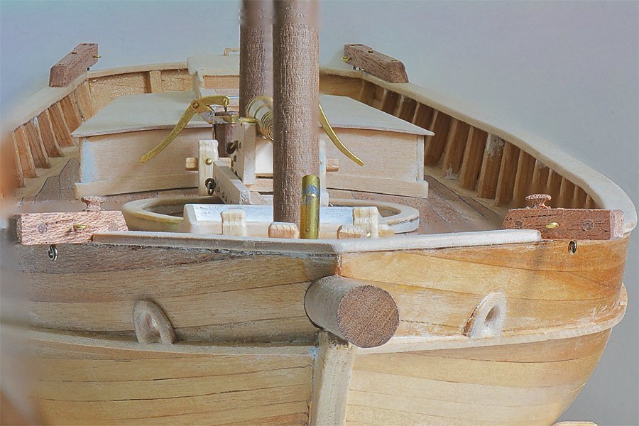
-
Allan, I used rub-ons that had a noticeable thickness - probably vinyl. I am not familiar with the dry-transfer lettering you mention. Something else to learn about! The technique I described - using the rub-on letters as stencils - has one special virtue. You can use the technique on contoured/textured surfaces and the resulting painted letters conform perfectly with the pattern in the surface. It is difficult to get decals to do this, even with the decal setting solutions, and I can't imagine getting a rub-on to conform to a textured surface. By textured surface I mean vent louvers, corrugated panels, etc. Rub-on work fine with smooth surfaces.
-
If you have painted something with a thin glossy finish and you want semi-gloss you can just rub it with 0000 steel wool. Just be sure the finish is dry/hard before you use the steel wool. After rubbing with steel wool rub with a clean cloth to remove any fragments of the steel wool. The white stuff used on hull bottoms was something like white lead and tallow. It sealed the wood and inhibited marine growth. It wasn't as good as copper, but was a lot cheaper and easier/faster to apply. Again it was a matter of cost.
-
I have used rub-on letters in a rather unorthodox way to get neat permanent lettering on models (rub-ons may peel off after a few years). Rub-ons are fairly thick at model scales. This is OK if you are modeling wooden or metal letters/numbers that were attached to the ship. But they are unrealistically thick for painted letters/numbers, so I use them as stencils for painted letters. 1. Paint the surface the color of the letters. Let it dry thoroughly. 2. Rub the desired lettering on the painted surface. 3. Paint over the letters with the desired surface color. Airbrush is best for this. Let it dry. 4. Carefully peel off the rub-on letters/numbers. I originally did this in desperation because I needed some lettering in a font and color that was not produced in decals or rub-ons. But the correct font was available in rub-ons in different colors. The result was perfect letters in the correct font and color, they had no raised edges like decals or rub-ons, and they were permanent.
-
The friction of the wheels does absorb some of the energy, but as you can see from this video, the gun does recoil until the breech line stops it. In this video there is no breech line and the gun rolls quite a distance.
-
Hi Paul, It's been a while since I visited your build. You asked a couple of questions, and it looks like you solved the problems nicely. Like you, I have planked directly on bulkheads. They often are not all the correct height. I use a strip of planking to find the low ones and add a bit of wood to the top. When they are all about the correct height I use a long sanding block to make final corrections. Then the planks go down in a smooth deck. I envy you having the real thing to visit while you build your model.
-
Greetings from Corvallis!
-
Gaff sails and backstay rigging rules
Dr PR replied to Michelnou's topic in Masting, rigging and sails
John Leather's The Gaff Rig Handbook has information and drawings for fore and aft rigs. Some of the information applies to 19th century ships, but there is a lot of information about 20th-21st century vessels, including racing yachts. It has quite a bit of the history of gaff rigs, but not very many actual sail plans and rigging diagrams. -
Mike, Colors varied by nationality and by the cost of pigments. In the early 1800s in America there apparently weren't many choices. Howard Chapelle says in The Baltimore Clipper (Edward W. Sweetman Company, New York, 1968, page 170): "The painting of the hull seems to have varied widely as yellow, black, green and blue were used, with white or black bands. On privateers, the inside of the bulwarks were often painted red or brown, but the decks were usually bright [unfinished]. Yellow and black were popular colors, however, for pilot boats in 1812-1814. They had yellow sides with black mouldings, wales, or trim. Very few were painted white, as it made them too prominent at a distance, which was considered naturally, a handicap during the war." And that is the entirety of the references that I have found specific to the colors of Baltimore schooners! If it was a navy ship it would be painted with standard navy color for the nationalitys. However, in the late 1700s and early 1800s American ships were often painted in British colors, although the US Navy had no official colors until sometime in the 1820s or 1830s. Some captains or ship owners used unorthodox color schemes. I have read that deck houses and other deck furniture were often the same color as the inside of the bulwarks, at least up to about 1840 (red is popular with ship modelers). Then white deck furniture became popular. If you have ever been on a pitching deck in a rough sea on a dark rainy night you will appreciate the virtue of white or light colored deck furniture! I have also read that less expensive ships were painted with the least expensive paints available, and Baltimore schooners were usually cheaply built.
-
Gaff sails and backstay rigging rules
Dr PR replied to Michelnou's topic in Masting, rigging and sails
I have been following this thread with interest. Most of the Baltimore schooners in Chapelle's The Baltimore Clipper do have one or two backstays rigged high on the fore and main top masts and leading down to the channels (aft of the shrouds) where they were rigged with deadeyes (often smaller than the deadeyes for the shrouds) or just eyes with lanyards to hold them taut. Because these ships had extreme rake to the masts the channels were not far aft of the masts and the back stays were almost vertical. This allowed the fore boom (if any) and main boom to swing fairly wide, and the gaffs could swing far out to spread the sails for catching following winds. However, in some cases the main mast had a backstay that ran far aft to the bulwark. These had a tackle with one block anchored to the deck (or hooked to an eyebolt in the deck) and the other on the stay. The running part was attached on one end to a block and the free end was secured to a cleat or belaying pin on the bulwark. When running with the wind the windward backstay was pulled taut to take the strain and the leeward was slacked (and even unhooked) to allow the main sail to swing wide to catch the wind. **** The mainstays were rigged in several ways. The simplest was just a stay that ran from the main top to the fore top above the fore gaff. That way the stay did not interfere with the gaff. The forestays took the load on the main mast. Some plans show fixed dual mainstays (or mainstay and preventer) that ran from the main top to knightheads on deck forward (larger ships) or aft (smaller ships) of the fore mast. In these cases the fore gaff sail (or foresail) did not have a boom, but had port and starboard sheets to the clew (lower aft corner of the sail). When tacking the foresail was hauled over the mainstays with the sheets. They often had a brail to haul the clew to the fore top to help pull it over the mainstays. A third and apparently common method of rigging the mainstays was as mentioned above. Two stays ran from the main top forward to the port and starboard bulwarks forward of the fore mast. They were rigged with a tackle with one block anchored to the deck (or hooked to an eyebolt in the deck) and the other on the stay. The running part was attached on one end to a block and the free end was secured to a cleat or belaying pin on the bulwark. When the ship was tacking into the wind (the force of the wind pushing aft on the sails and mast). the windward side mainstay was pulled tight to take the strain on the mast and the lee side was slackened to allow the fore gaff sail to swing wide to catch the wind from the jib. **** With the tackle rigged backstays and mainstays a change of course or wind required adjusting the stays so the windward stays took the forces on the mast (the leeward stays did not carry a load so they could be slackened to allow more freedom of movement for the gaff sails. **** All of these arrangements seem to be used in modern schooners. If you examine photos closely you can see the same ship with mainstays and backstays all rigged taut or the lee sides slacked when under sail, and not rigged at all when motoring in and out of port with sails furled. -
Any measurement taken from a printed drawing is subject to many errors. As mentioned above, line widths make finding dimensions problematic. Some printers do not actually print to scale and add some error to the measurement. However, this isn't always a big problem. Things are not built to random dimensions. Engineers usually work in some units of measurement (inches, feet, millimeters, meters, etc.). For WWII US ships things were designed in feet, inches and fractions of inches (1/2, 1/4, 1/8 and occasionally 1/16 and 1/32). It is a lot simpler if the original units are metric! Engineers usually don't design things in odd fractions, like 1.297 inches. If your measurement from the drawing scales to 1.297 inches (1:1 scale) it's a good bet that it really should be 1.25 inches. If you know the units of measure (inches, mm, etc.) the part was designed in you can correct some of the measurement errors by rounding to the nearest common fraction.

