

jpalmer1970
-
Posts
335 -
Joined
-
Last visited
Content Type
Profiles
Forums
Gallery
Events
Posts posted by jpalmer1970
-
-
-
1 hour ago, allanyed said:
An alternative that I switched to some years ago is to print on full size sheets of label paper. Cut out the drawing of the part somewhere near the lines, peel off the backing and stick on the wood.
That's another good option Allan, especially if you can get easy peel off labels. Some price tags or manufacturers labels are a devil to get off cleanly when the glue is stronger than the strength of the paper!
-
9 hours ago, Stuntflyer said:
In certain cases, rather than shaping each section individually, I just cut the joints accurately and then join the various sections together. After doing that it's easier to get a more accurate outline of the joined parts while the templates are still attached.
That's a great tip - thank Mike.
I have some Elmer's School Glue and various types of glue sticks so I will experiment and see what works best. I guess you need the template to stick well but also come off cleanly when you are finished with the template. Certainly so far from my very limited experience, I think I am finding it easier to work with pieces with paper templates rather than just pencil outlines directly on the wood.
-
9 hours ago, dvm27 said:
You should cut as close to the line as you are comfortable doing without cutting into the line. I used to leave about 1/16" using my scroll saw then sanded to the lines on my disk sander or oscillating spindle sander. After some practice I'm able to cut to within a whisker of the line and that is sufficient. Fairing after the hull is assembled will blend everything together.
Thanks Greg. I appreciate the advice. I need a lot of practice and hopefully experience will eventually come my way 👍
-
-
9 hours ago, VTHokiEE said:
I think that how close you get to the line probably depends on the part. My experience with the frames on my cross section was that I should have left a a good bit more on the parts than I did to account for fairing (maybe leaving 1-2 mm? outside the line to account for fairing)
Thanks - this sounds like very good advice. 👍
-
12 hours ago, targa4403 said:
Apparently the use of this part to extend the lathe bed it not recommended by the manufacturer. I don't know the reason why. Maybe it will affect the performance of the motor? I don't know. I just saw this on the internet. Have you had any issues with the bed extension?
I haven't found any problems so far. I have only used it to extend the length by a few centimetres rather than the whole 450mm though. If you are working on a longer spar or mast it is nice to have the whole length you need to work on available outside the collet to avoid any marring. It also helps ensure the collection isn't holding a tapered piece of the spar which could bring about wobble.
-
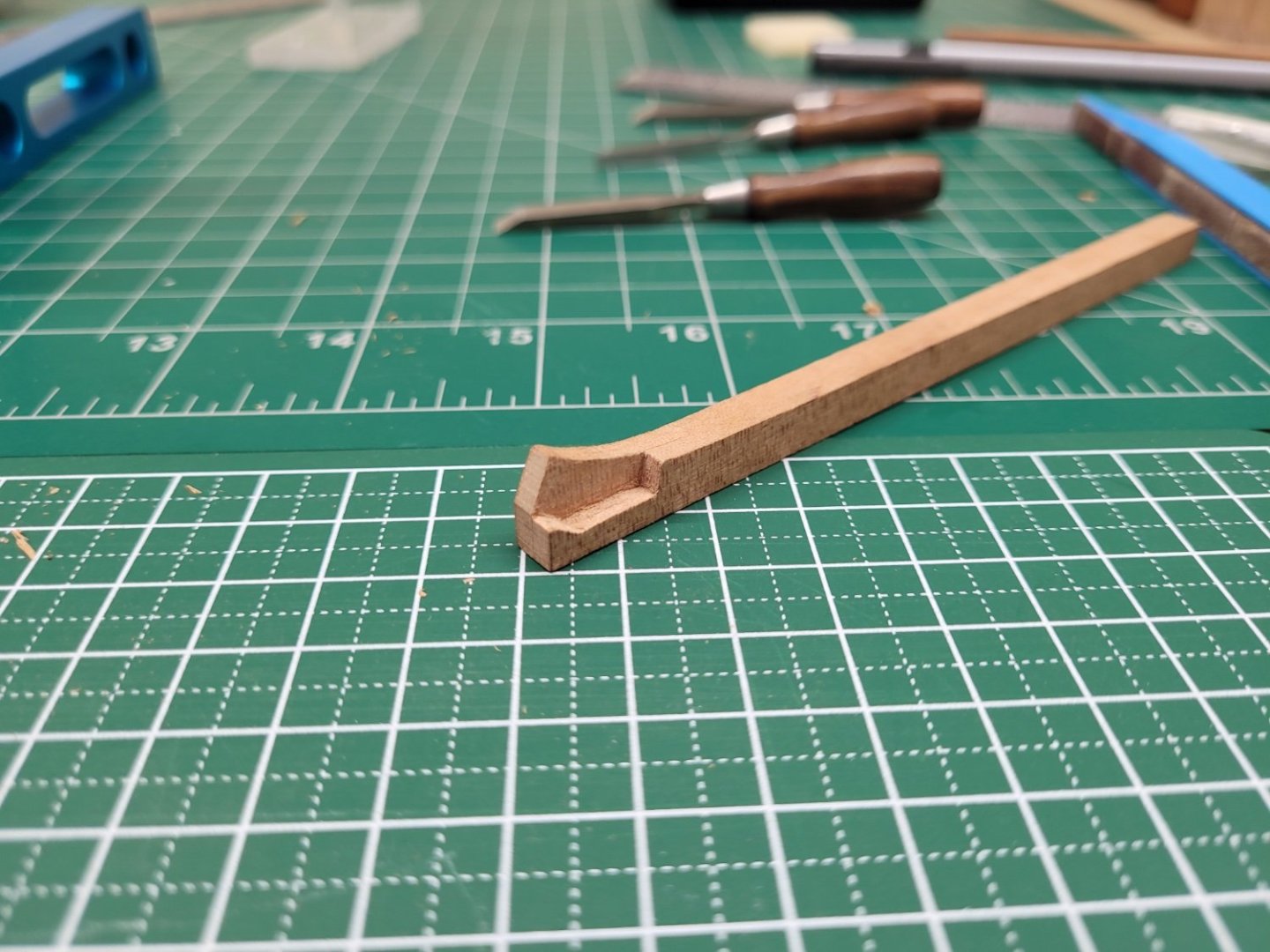
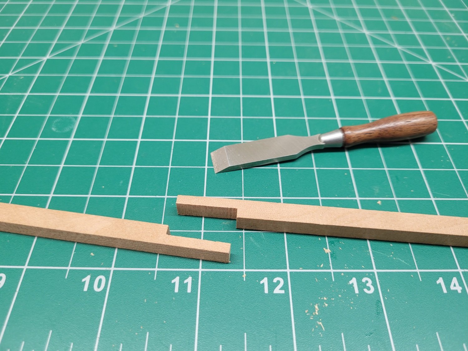
As it is a holiday weekend I was able to spend a little more time on the model. I did cut out the boxing joint on the forward section of the keel with my small chisels but I wasn't happy with the result as I shaved a little too much off the 'tooth' (it probably has a proper name but I'm not sure what it is!) at the end. The temptation just to tidy things up a little is very strong - until you go too far! Consequently I remade that part of the keel again and redid the joint, this time taking much more care with the chisels and only working on specific sections of the joint at a time. The second iteration of the joint was much better that the first attempt and so I'll see how I go when I cut out the lower part of the stem joint before deciding whether this is a keeper. I used my mini mill as a spindle sander to help shape the curved sweep of the top of the piece.
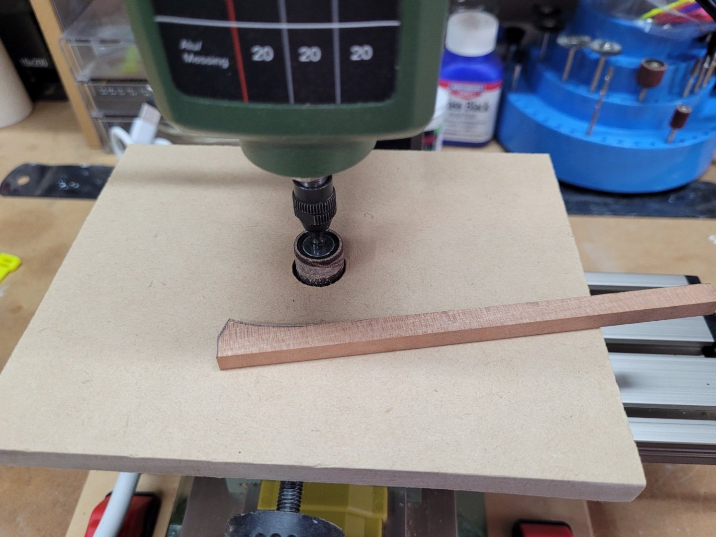
Here is the second version of the forward section of the keel with the boxing joint.
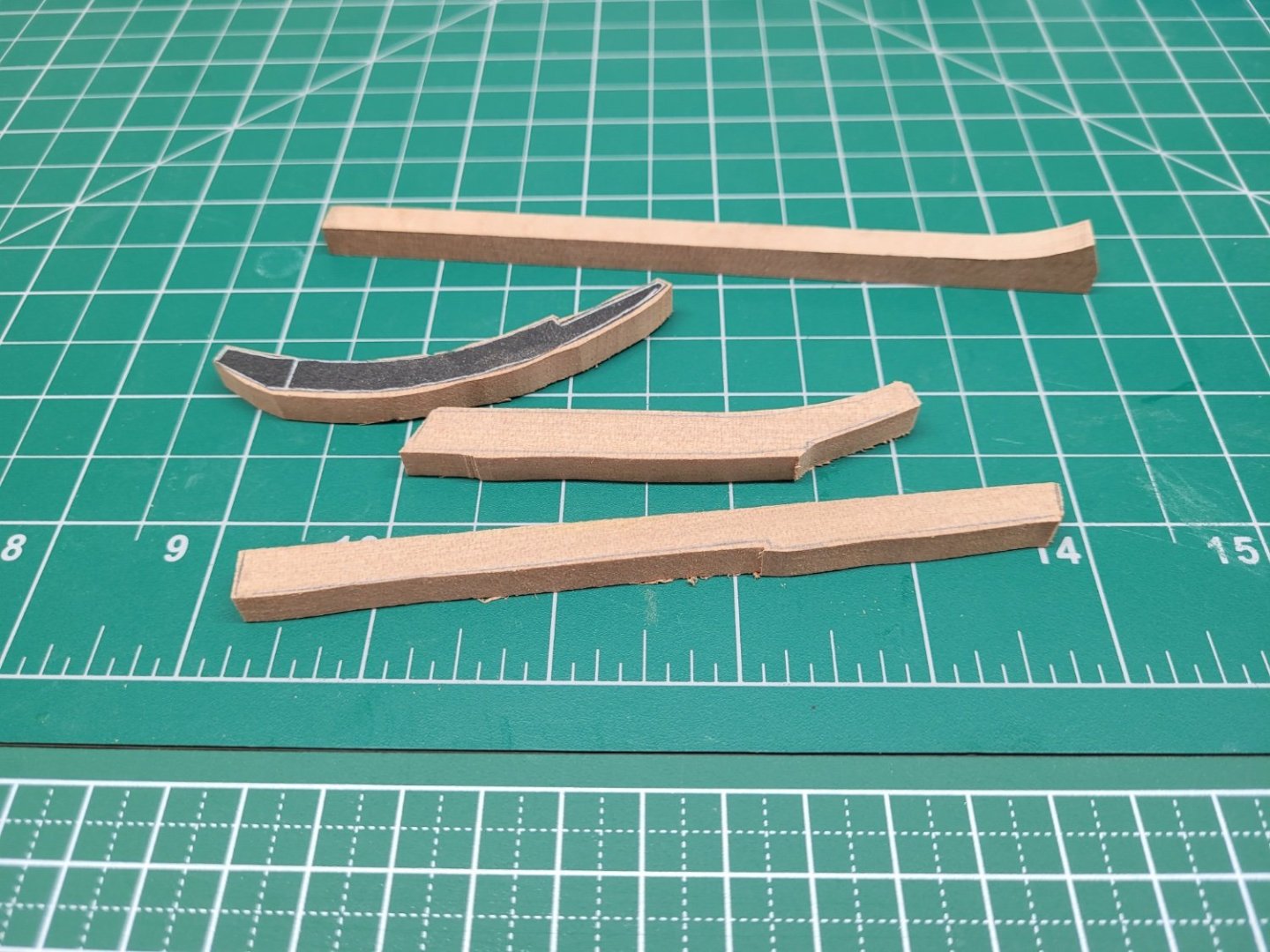
I also cut out the lower and upper stem pieces and the outer keel post from the 12" stock. I experimented with tracing out the shapes on the wood and also gluing templates on the stock before cutting them out on the scroll saw. I'm not sure which is the most accurate way to use going forward but the cut out templates certainly seem to be easier to see, for me at least. I'm also finding difficult to judge how much excess to leave on the piece with the scroll saw - I realise you need to be close enough so you don't have to do too much sanding to shape but at the same time you need to have enough excess to make sure you are not going to end up with an undersized piece. No doubt I will get better at this when I start cutting out the dozens of pieces that make up the frames!
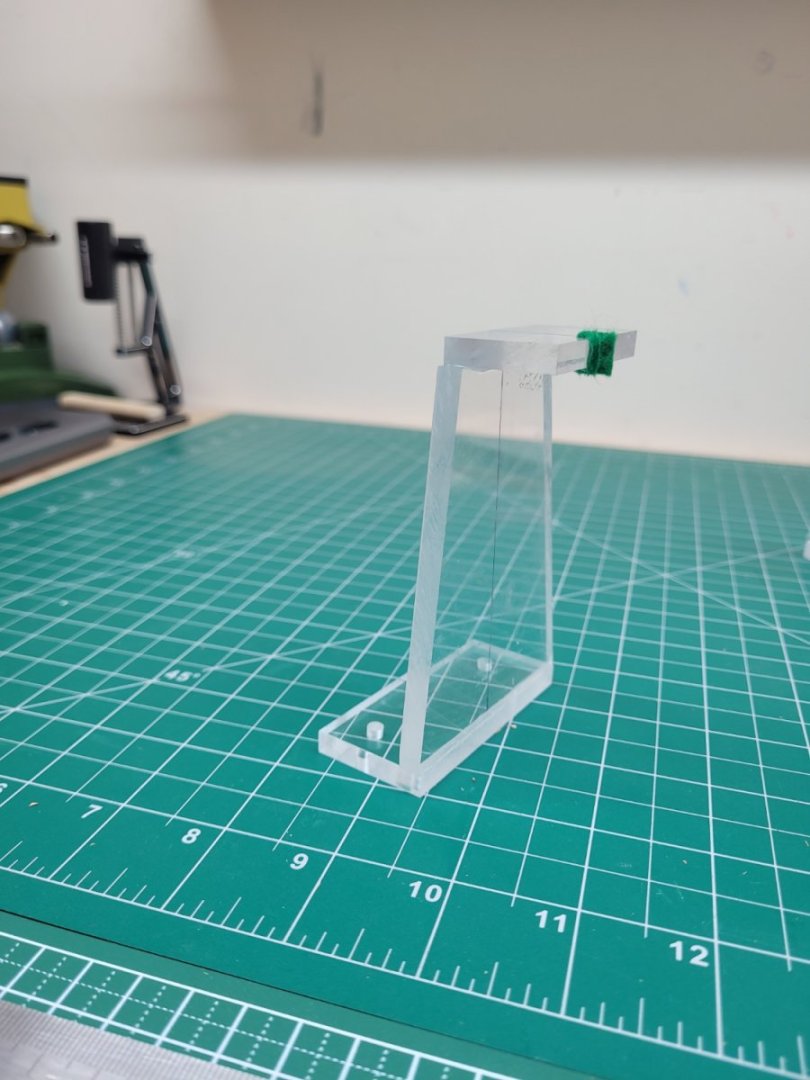
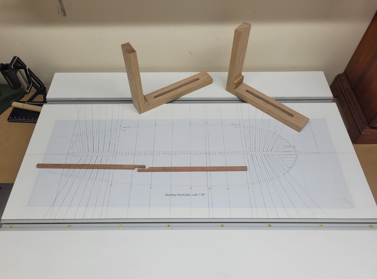
I also used some 6mm acrylic to make the support mounts for the stem and the stern. They may not be the prettiest supports ever but they are square and after lining the cutout with sticky backed felt a 12" timber fits in there nice and securely.
I think the next job will be to trim the keel sections to length and cut the scarph joint for the forward section of the keel.
-
16 hours ago, barkeater said:
I have the Proxxon and use the add on 3 jaw chuck like Rob. The pass-through ability is key as it allows for longer stock and helps avoid whipping.
There is also a 450mm extension bed for the Proxxon DB250 which I have found to come in handy from time to time.
-
This will be interesting to follow. 👍
- Pirate adam and mtaylor
-
 1
1
-
 1
1
-
Thanks for the support and encouragement everyone.
The artists' varnish doesn't say whether it is water based or not but druxey is no doubt correct. The spray can does indicate it can be used on drawings and artwork but it does mention 'fine art paper' and I guess that is the where the difference comes in. My plans certainly aren't printed on 300lb cold pressed paper and presumably the thickness of the paper is a factor.
-
Hello,
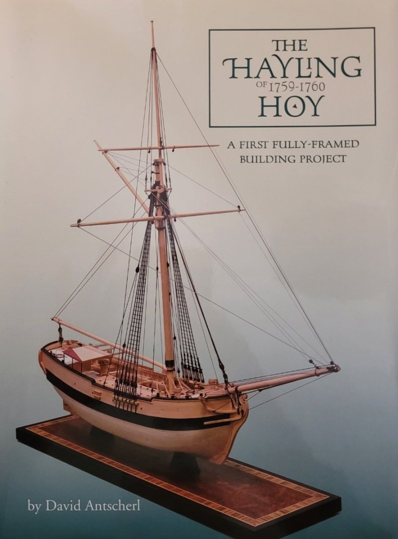
Welcome to my build log of the Hayling Hoy. David Antscherl's excellent book on this build says that it is suitable for a first time builder attempting a fully framed model. Well, I am certainly a first time scratch builder and this will be my first fully framed model so I hope he is correct! I decided to attempt this build as I wanted to stretch my skills and techniques and also because I knew it would be a very long project. I really don't have that much spare space to display finished models and so the longer I can keep one on the building board the better! I was impressed and encouraged by previous first time scratch builders who have also attempted this build, notably @Stuntflyer and @Seventynet and I hope I can come up with something that even approaches their excellent work.
I have no background or experience in woodworking and whilst I do own a few of the machines that may help with this build, eg table saw, thicknesser, mill etc I haven't had a great deal of experience using them to date and so this will be a learning experience for me on those tools as well as in regard to the techniques of scratch building a fully framed model. There will be plenty of mistakes and do overs on the way but I'm not worried about that as it will all be a part of the project. I will of course welcome any advice and ideas from people who feel that they would like to contribute. I know I have a lot to learn and I am looking forward to it. Progress is going to be slow as I don't get that much time each week to devote to modelling but hopefully I will keep going forwards!
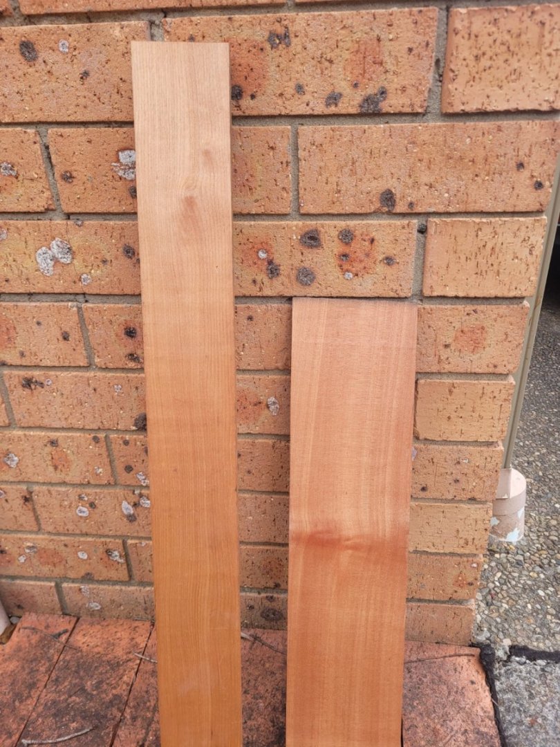
Being based in Australia I really don't have access to the lovely types of wood I often read about on this forum but there are of course native options. I have decided to use some myrtle that seems to be in readily available supply. So far I have only purchased a couple of small pieces just to get started with. The myrtle seems very like pear wood (to my untutored eye at least) and hopefully will make a lovely coloured model with fine graining.
I have spent that last few weeks getting ready to start this project and that included getting the plans copied and making my building board. I used some mdf for the base of the board and added some pine battens underneath. I have seen a couple of builds that use t track as part of the building board and so I decided to copy that idea and I also made some wooden squares to use with the t track. I added a couple of coats of white paint to the board and then glued down the plan using some spray adhesive. It seemed like a good idea to add a coat of artists' varnish over the plan but clearly that was a mistake as it only succeeded in introducing lots of wrinkles - so that wasn't a good start. Either I hadn't glued the plan down sufficiently or the spray varnish just didn't like that particular paper. So off with that plan and on with another copy, this time glued down with lots of Bostick blu stick - and it seems to be sticking well so far. I didn't bother with the varnish this time around. I also extended the lines of the frames out onto the board which should hopefully make things easier to line up and keep square etc down the track.

Today I actually made a start on the build itself and began with cutting out the pieces for the keel. The keel is made of three separate pieces joined with scarps joints. The rear two pieces are simply 12" square lengths and I deliberately made them over long as I wanted to make sure I had plenty of excess to work with in case I made a mess when cutting the scarph joint. The scarph joints were cut on the table saw and then the faces of the cuts tidied up with a small chisel.

Strangely, the keel sections look far from square in that photo above but it must just be the perspective - they are square honestly!
Next job is to tackle the forward section of the keel with the boxing joint.
-
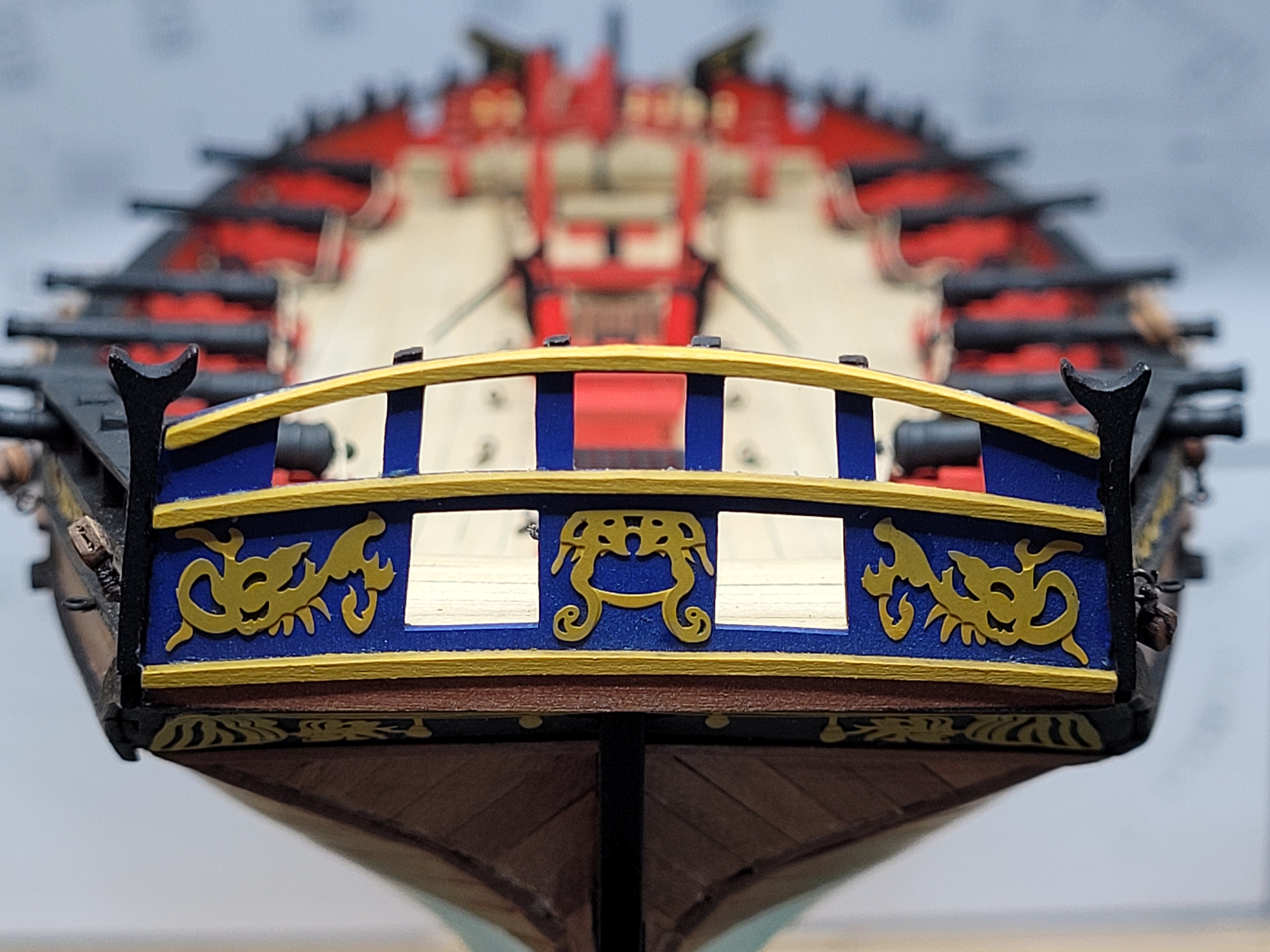
That's a great idea for the knotted handrail - excellent work
- Glen McGuire, Thukydides and AJohnson
-
2
-
1
-
Great work for your first wooden kit Richie. It seems AL have revamped this kit which is good - and hopefully the instructions have been greatly enhanced from the old version. A single layer planked open boat is a challenge for any new builder as you can't hide any planking mistakes under a second layer! Well done with you work so far.
-
Hi Bill,
Looking forward to seeing your progress with this build.
-
Excellent work. You have made lots of great additions to bring this build to a very high level.
- Glen McGuire, Mr Whippy, Thukydides and 1 other
-
3
-
1
-
-
-
21 hours ago, AJohnson said:
I will be interested to see your work on the Hayling Hoy, I have that book and like you feel it will be the cause of much sawdust and cursing on my part! So it sits on the book shelf for now…
I plan to have a build log for it, where I will hopefully reap the benefit of advice and guidance from more experienced scratch builders. It may be a couple of months before I am up and running with it but please do look in 👍
- AJohnson and Bryan Woods
-
2
-
5 hours ago, jpalmer1970 said:
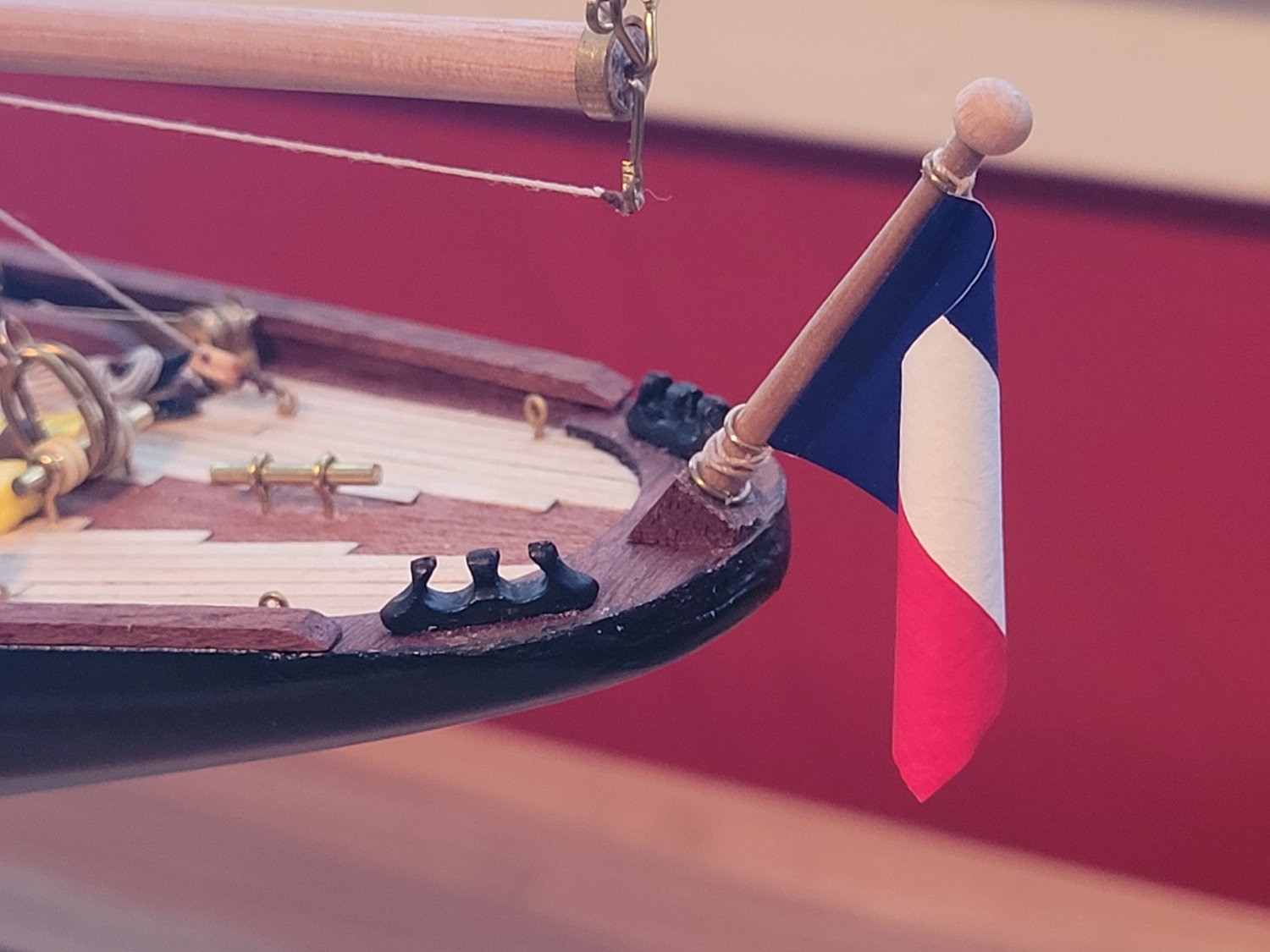
I realised this morning that I had actually omitted to glue on the little round ball that sits on top of the ensign staff
OK, now the model is finished! 😁

- Bryan Woods and BobG
-
2
-
14 hours ago, Thukydides said:
Do you have any plans for what you want to do next?
Next on the list is a very quick build of a Napoleonic French field gun.
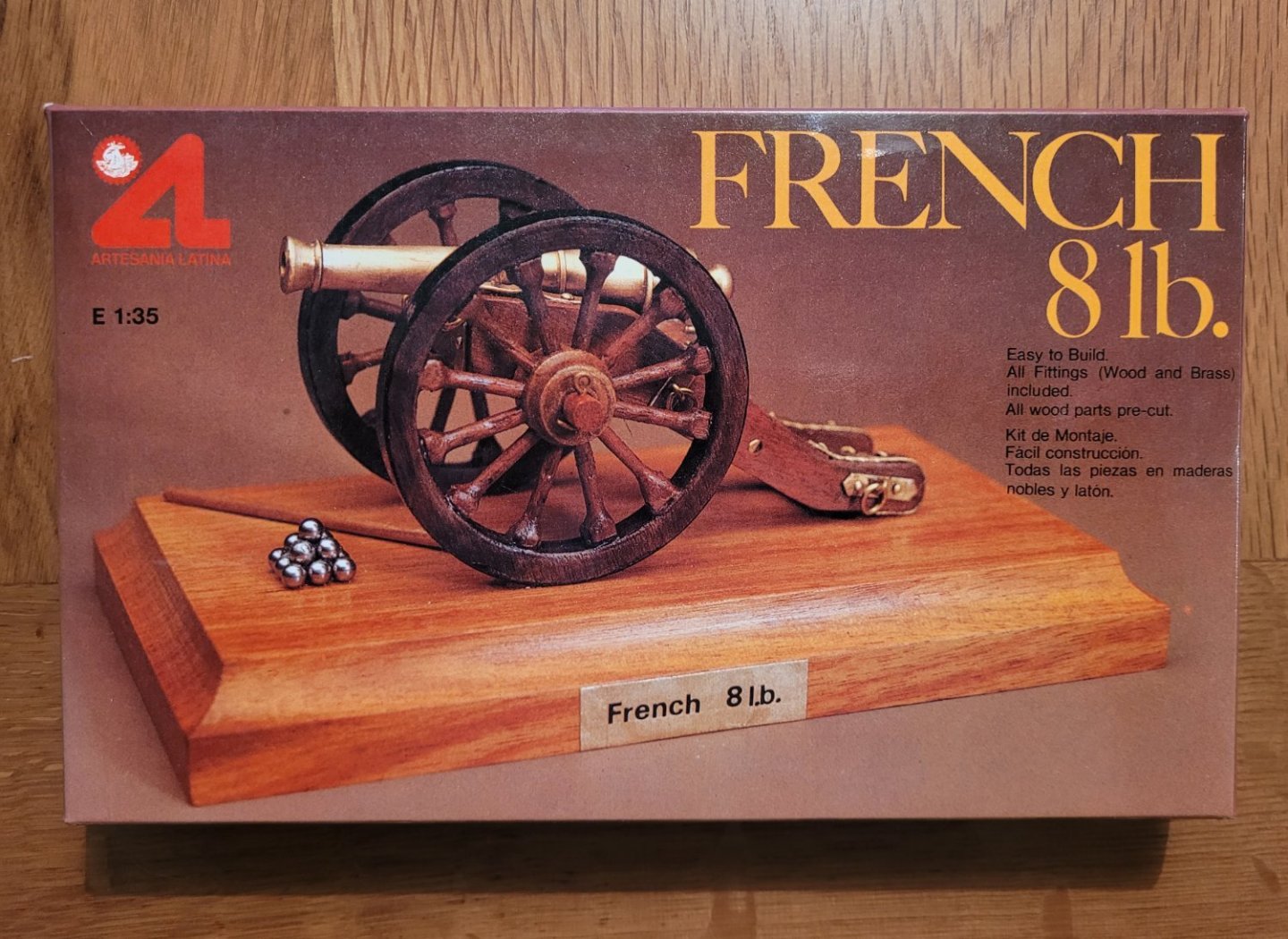
After that I will be returning to ship building and I'm going to try my hand at a scratch build of the Hayling Hoy.

I must admit to feeling somewhat out of my depth with this as it will be a completely new level or woodwork for me. I have bought the required tools I need such as a thicknesser and scroll saw but have no idea how to use them properly 😀 I foresee that there will be a lot of sawdust and do overs. The Hayling Hoy will be a very long term project for me which works well because I don't really have a lot of space to display more models!
- hof00, Bryan Woods, Thukydides and 2 others
-
5
-
Thank you for all the kind words.
I realised this morning that I had actually omitted to glue on the little round ball that sits on top of the ensign staff - so the case will have to come off again tonight so that I can put that in place! 🙄
At least it gives me another opportunity to get wipe the case down again afterwards to remove the fingerprints! 😃
-
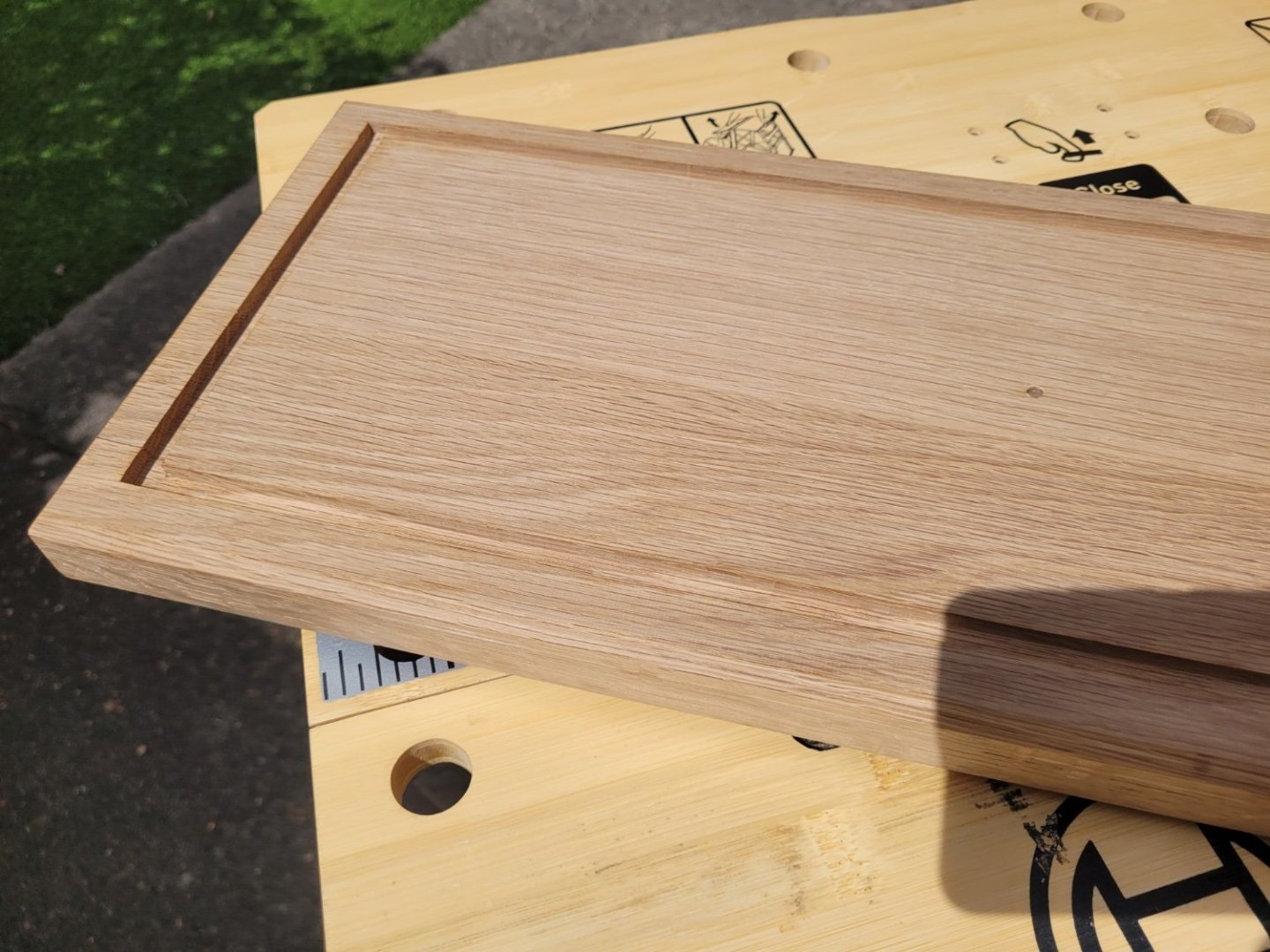
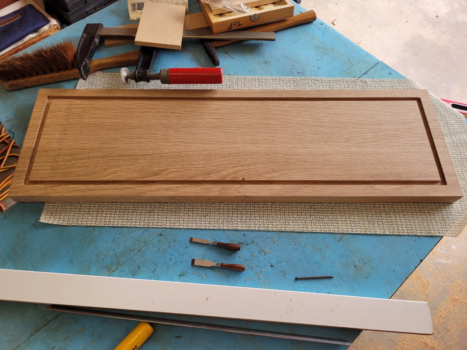
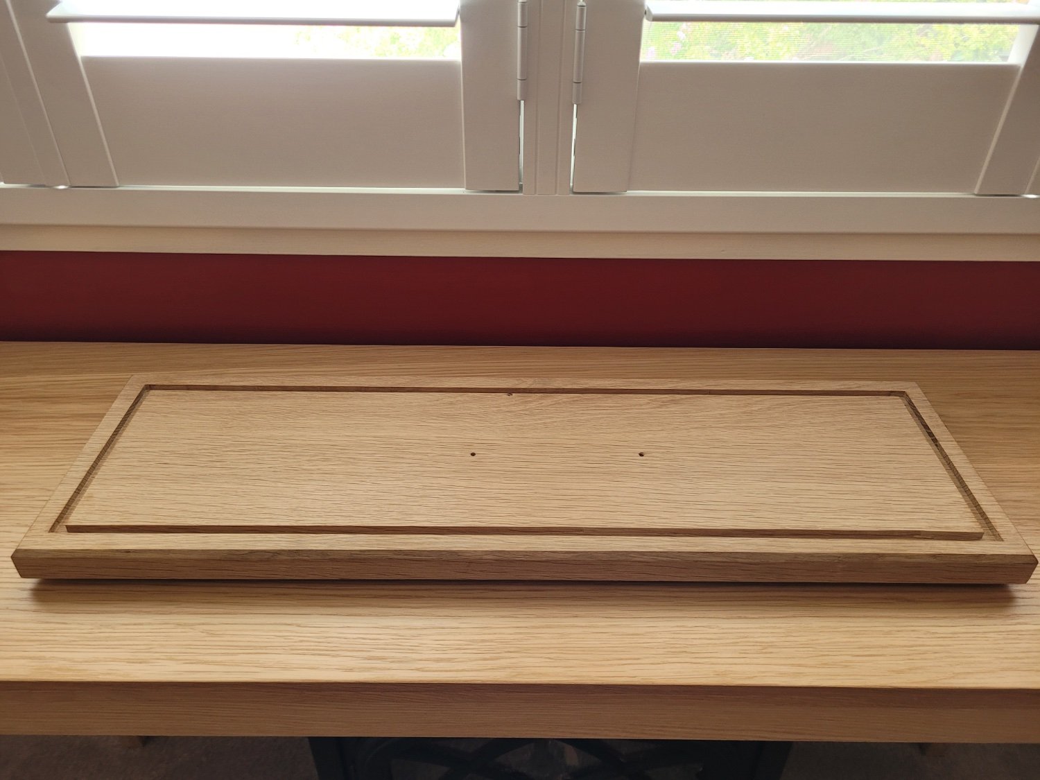
Yesterday I was able to undertake the routing required to shape the base board. My father-in-law kindly assisted with this (it's his router!) and we carefully marked out the external dimensions of the display case on the base board. As the acrylic is 6mm thick I used a 7mm router bit to make a 6mm deep channel in the base board into which the case could slot. The initial attempt was close but not quite right and so I had to widen the channel by 1mm towards the outside of the board on all sides in order for the case to slot into place nicely. To be honest we were both rather surprised we had managed it without too many problems!

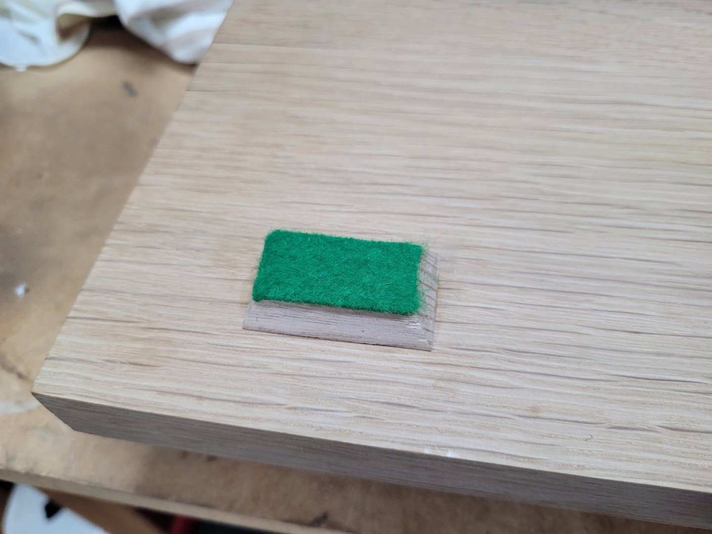
The corners of the slot were cleaned up with some small chisels and then the top of the board was given a good sanding. To make the base board a little more pleasing to look at I also chamfered a 45 degree angle around the top edge. I also attached the six oak feet that I had previously made, and added some self adhesive felt to the bottom of these to stop the base scratching the table on which it is placed.
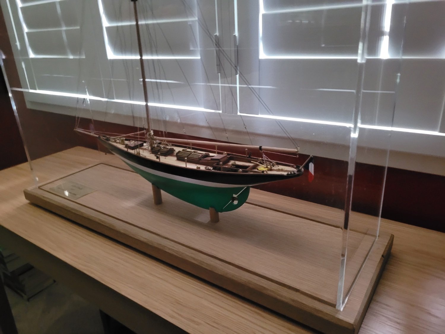
The next job was to drill the holes into which the brass rods could slot to hold the model in place in the board. It seems I hadn't quite installed the brass rods exactly parallel to the waterline when I put them in the hull off the model many months ago and so the holes in the baseboard needed to be slightly offset from vertical. I wondered about adding a coat of wop to the board and so tried a sample area underneath. The wop made quite a difference to the colour of the oak giving it a rather yellow hue which i didn't actually like, so I decided to leave the natural wood as is.

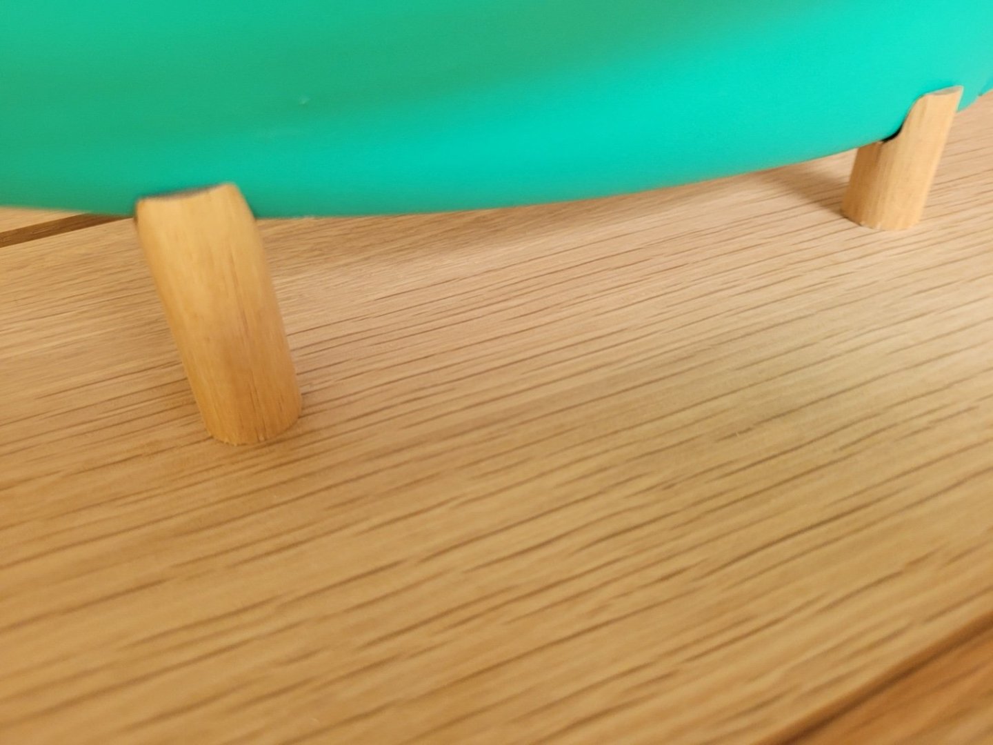
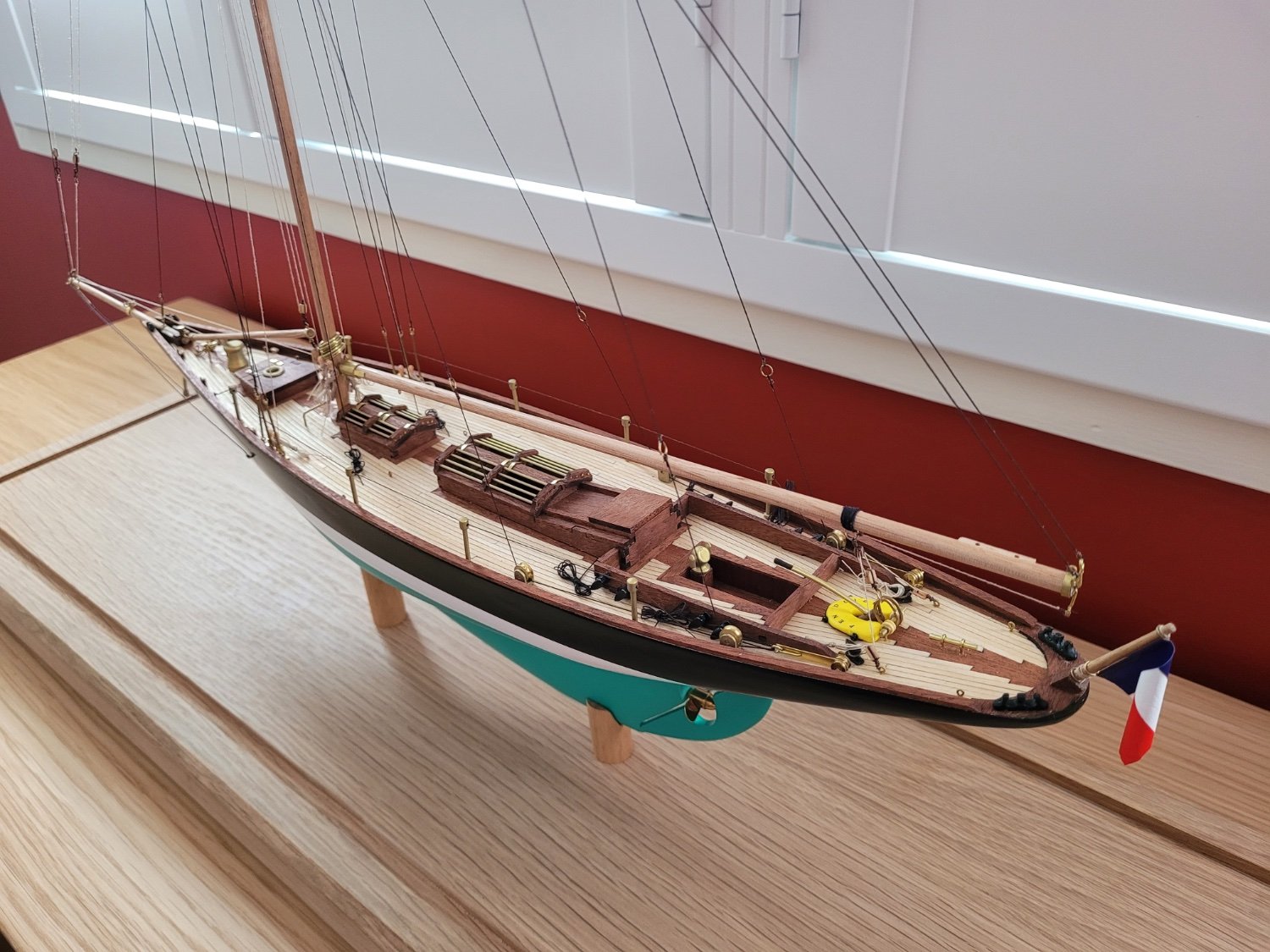
I also cut down the wooden pedestals I had made so that there was around a 15mm gap between the keel and the base board once the model was mounted on the pedestals. The pedestals simply slipped over the brass rods and some double sided tape held them fast on the base board. The brass rods extend about 18mm into the base board and hold the model in place very securely.
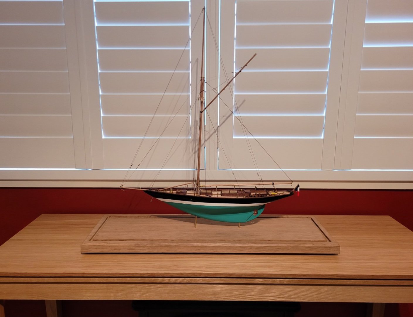
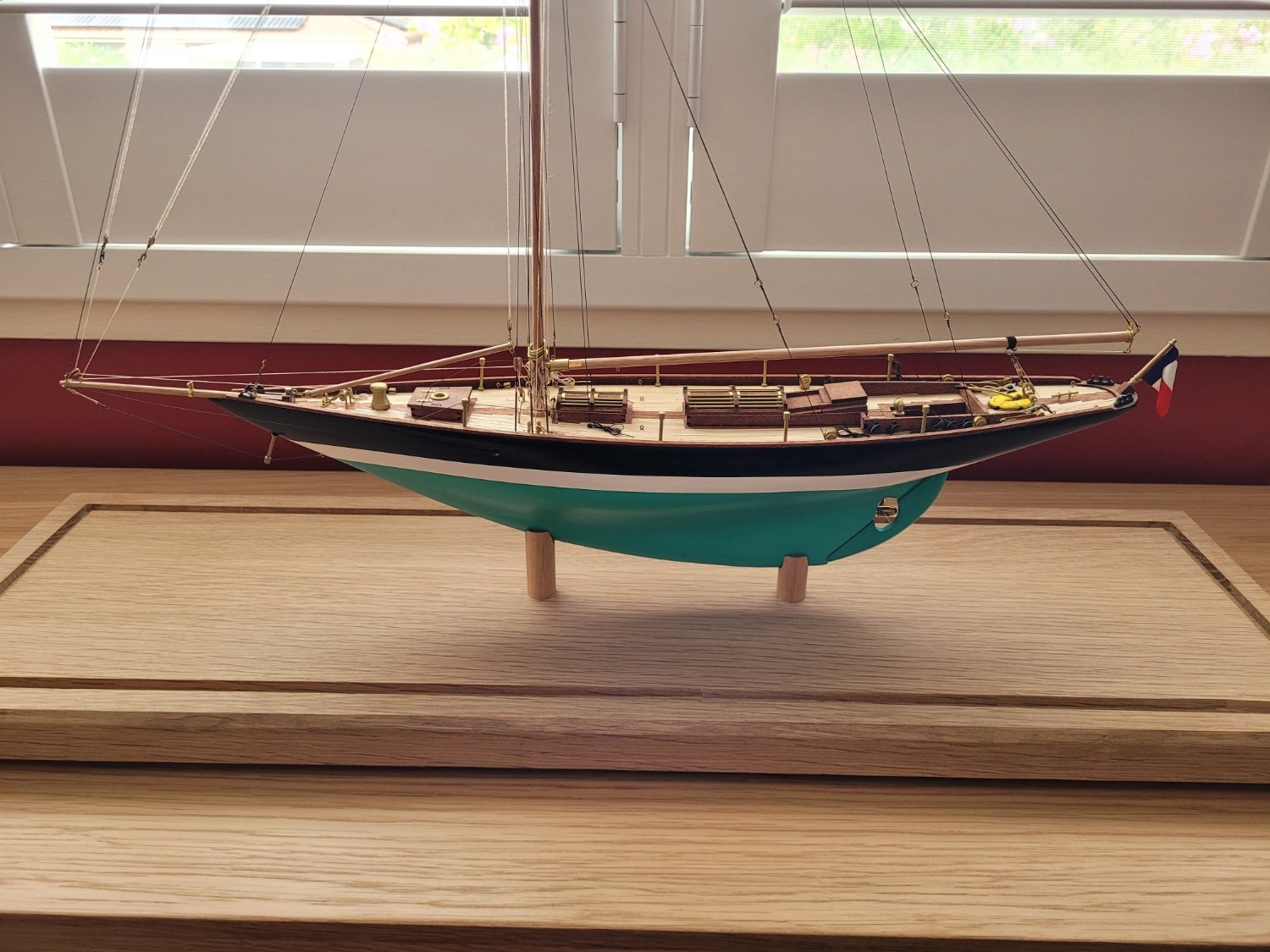
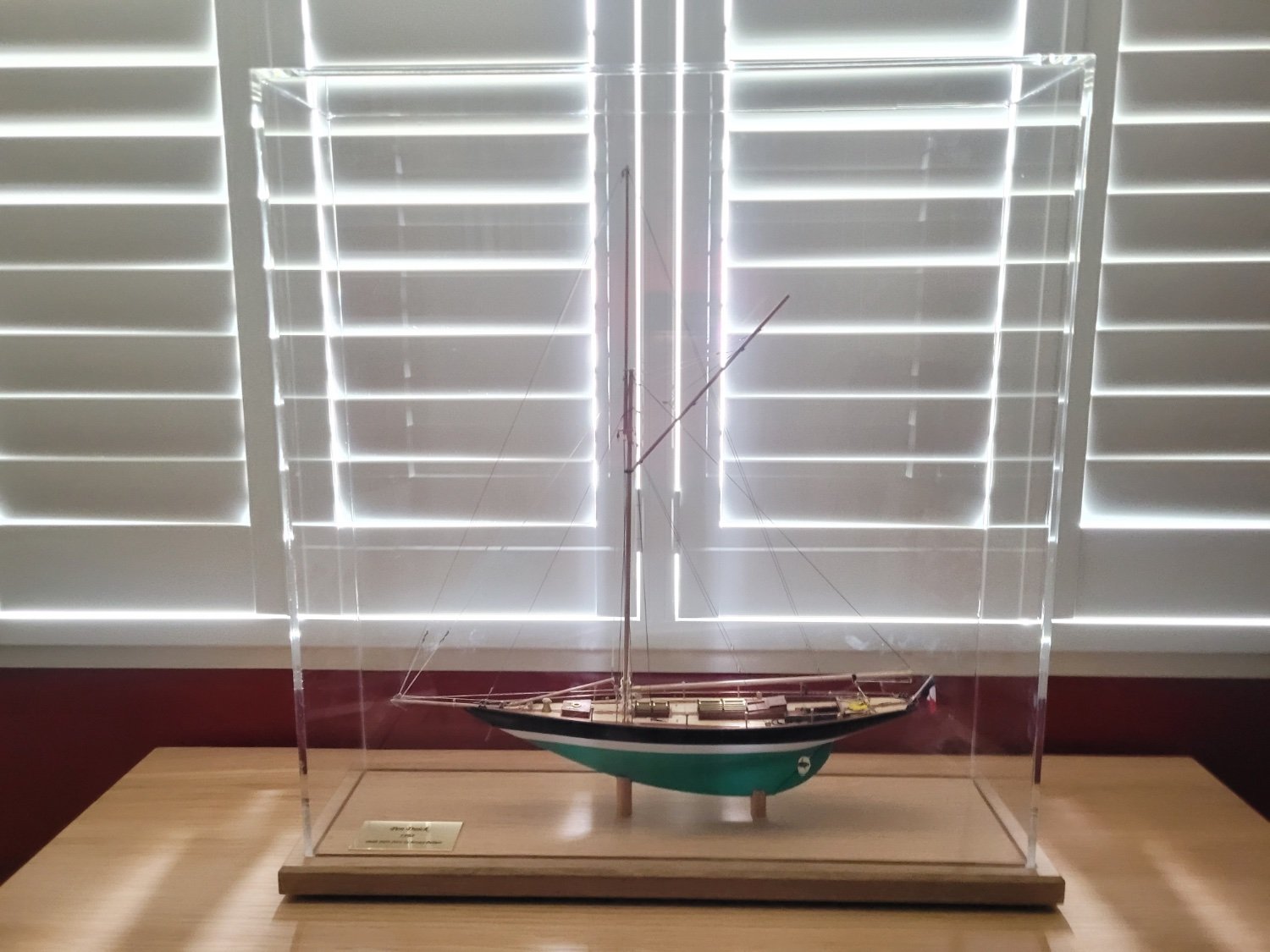
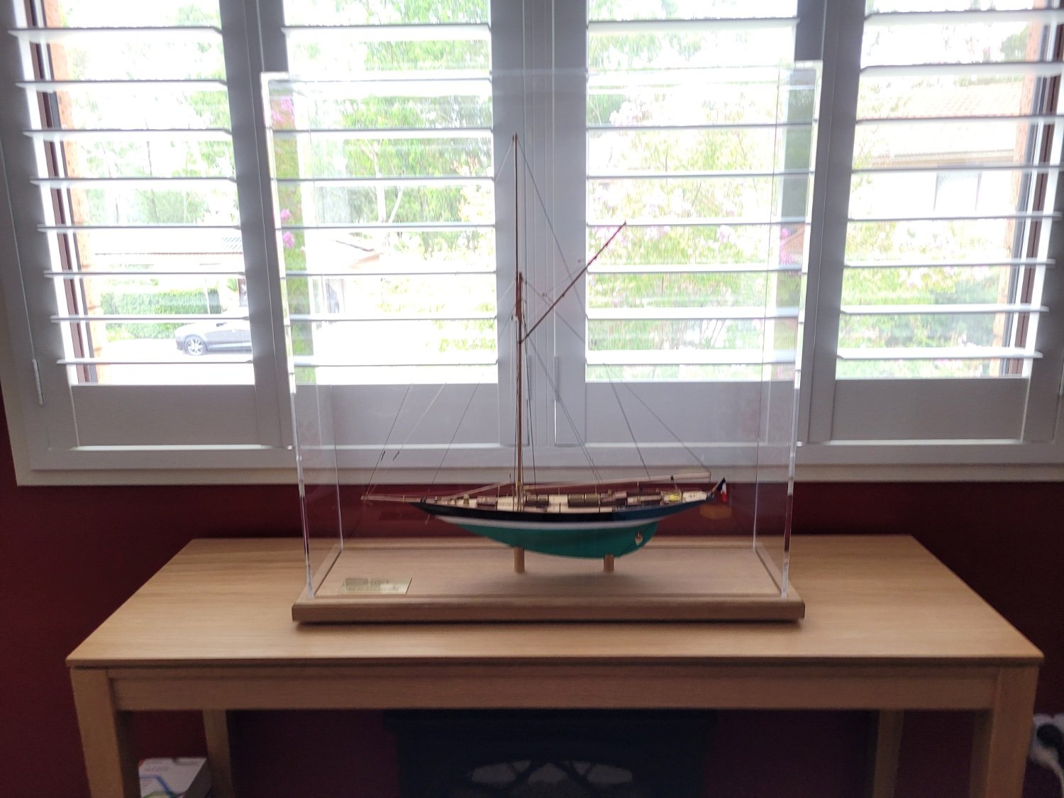
I also put some double sided tape on the back of the name plaque and placed that on the base board and took a few pictures of the model before adding the display case.


It was then a question of taking off all of the protective film from the case and doing my best to get rid of any finger marks and dust. I'm not sure how the protective film is attached to the acrylic but it once it has been removed it gives the case a lot of electrostatic attraction to dust, hairs and all other sorts of little bits of debris which makes getting it clean and mark free quite a task! I felt like I was just moving the dust around but eventually it came out looking good.
I carefully lowered the case over the model and into the slot on the baseboard and wiped off all of the fingerprints from the case. I then started to take pictures of the completed model for the gallery and it was at that point I realised that I had omitted to place the sprit and the yard on the deck, and so I had to carefully remove the case, put the two spars on the deck and then recover the model. Another round of fingerprint removal was needed before I could recommence taking pictures again. 😀


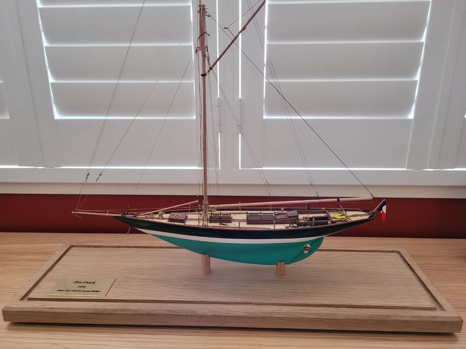
So I am now calling this one completed. I would like to thank everyone who has looked in on my build log, thanks also for the likes and comments, suggestions and ideas, and encouragement.
Some final thoughts on the model, the Artesania Pen Duick is a great model of a historic yacht. If you have made any AL models before you will know that the kits provide a good basis for a model but the fixtures and fittings are a little sub par. Certainly with these older AL models the instructions are also pretty minimal. The biggest hurdle to overcome was the practically non existent rigging information, and a lack of detail in the sparse information that was provided. The rigging of the model turned out to be fairly simple to do in practice, but it was quite hard to work out what was required and how everything connected. It is also a fairly good sized kit with a length of 543mm, so it doesn't take up too much space but at 1:28 scale the fixtures aren't too tiny to work with. If you have built any model ships previously you won't have any problems with the Pen Duick, and it does make a nice change from the 18th century warships! If you are happy to buy some replacement parts to help make the build easier and at the same time better, then you can end up with a great model.
Thanks once again for your interest in this build.
Jeremy
-
Thanks for the kind words and encouragement Bryan and Thukydides. I finished working on the base today and so hopefully tomorrow I will get everything together and finally have the model on display!
- Bryan Woods and Thukydides
-
2


OUTSTANDING Mini Drill
in Modeling tools and Workshop Equipment
Posted
I have one of these and find it much more useful than a dremel for drilling small holes for eyebolts etc. The slower speed compared to the usual rotary tools (500rpm versus 5000+ rpm) and the small size of the unit allows for more accuracy I think. The drill press is also useful on occasion depending upon what you need to do - I seem to be terrible at drilling straight by hand....
It is basically a motorised pin vise, and not a cheap one at that, but still useful for me.