

jpalmer1970
-
Posts
335 -
Joined
-
Last visited
Content Type
Profiles
Forums
Gallery
Events
Posts posted by jpalmer1970
-
-
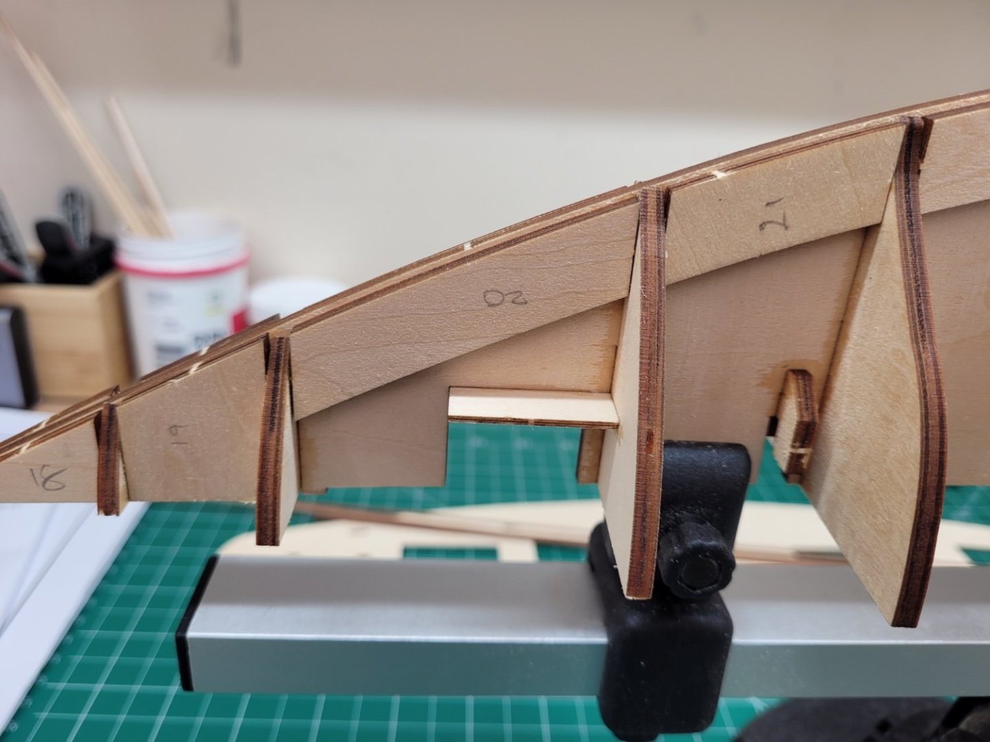
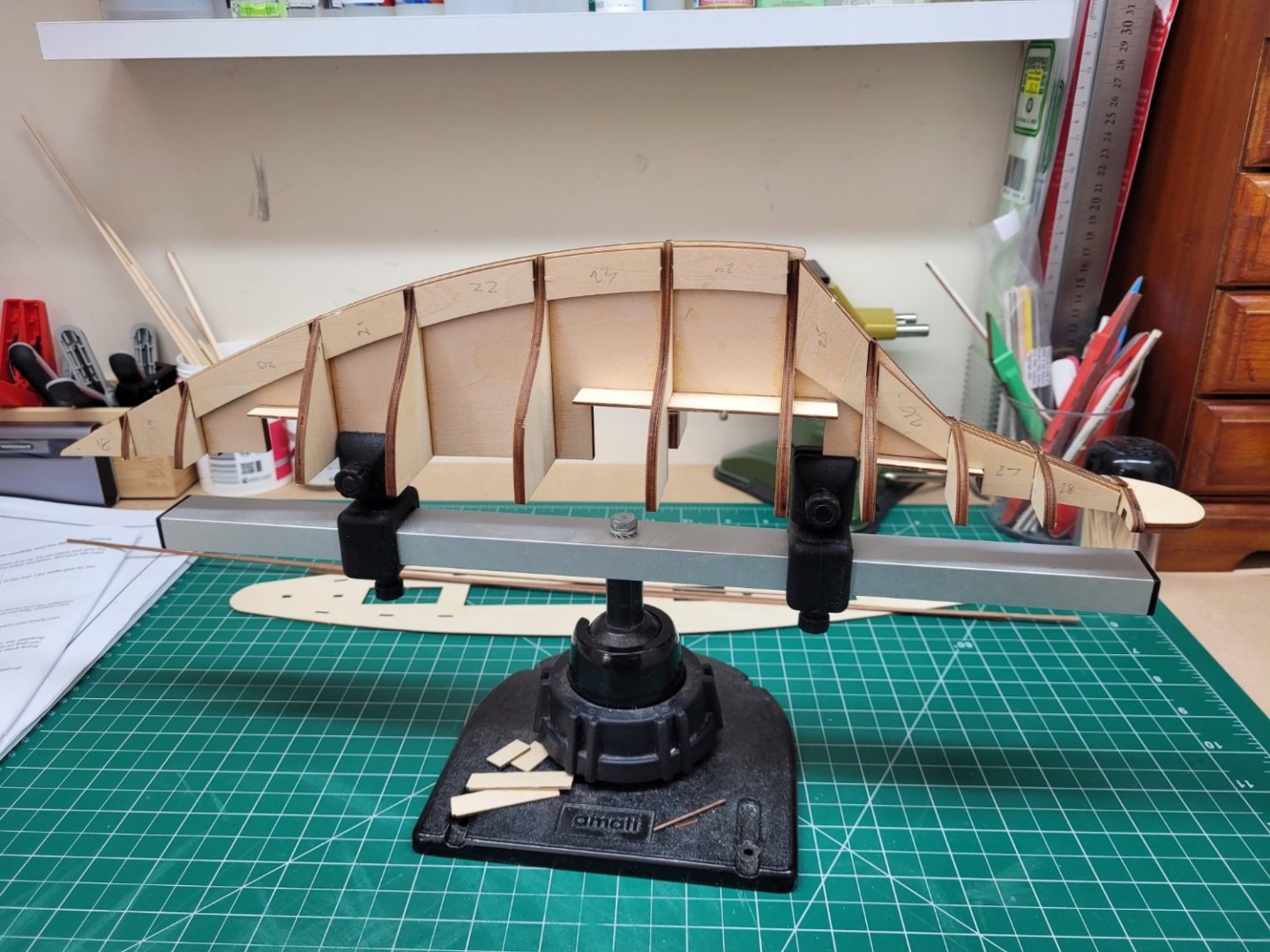
Today’s task was to fit the keel stiffeners, parts 18-28, on either side of the false keel. The written instructions merely indicate that these need to be glued either side of the keel but as @BobG pointed out in his log there is more to this than the instructions suggest. A careful look at the plans indicates that whilst the forward two pairs of stiffener pieces (18-19) and the rear four pairs of stiffener pieces (25-28) are sited flush with the bottom of the keel, the five middle pairs of stiffeners are actually located 1mm up from the base of the keel. I found a scrap of plank 1mm thick and used this as a shim to correctly gauge the positioning of these parts when gluing them into place.

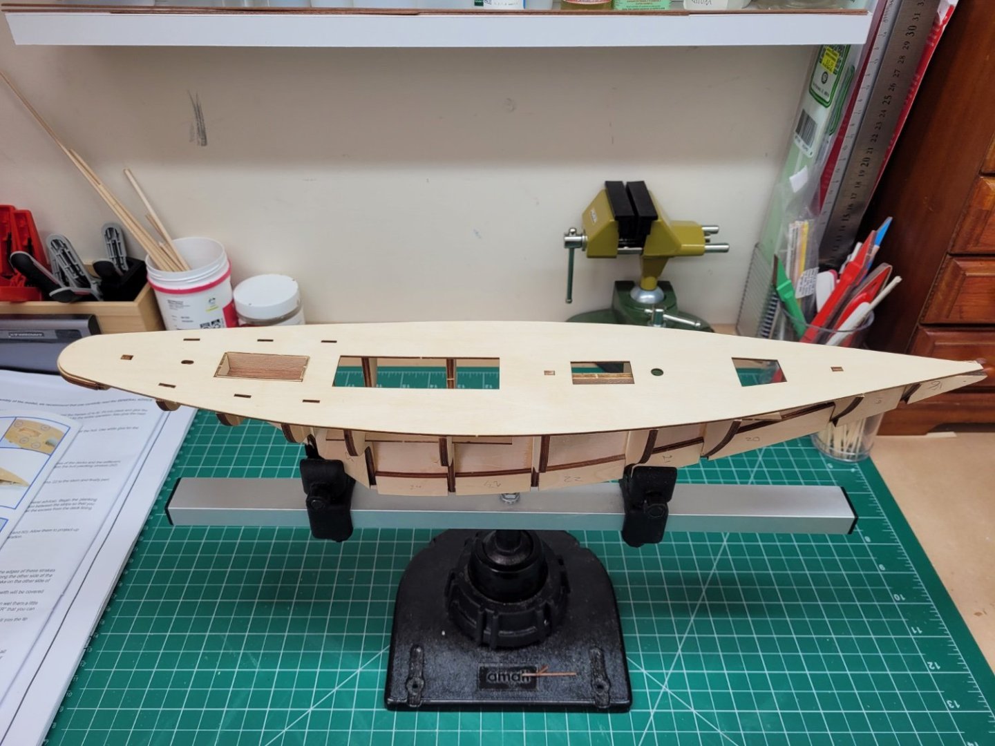
The next step in the instructions is to glue on the plywood deck and then frame the steerman’s hatch or cockpit. The cockpit floor and sides are planked with mahogany later in the build but it seemed to me that it would be easier to plank the floor of the cockpit now before the plywood deck was glued onto the frames. There are a variety of mahogany strips included with the kit and the instructions suggest using the 1x5mm sized strip for this. However, I was not very keen on using these as the strips in my kit are very mottled and the grain pattern is quite prominent. This strip is also later to be used for the framing of the deck hatches and I would prefer to have something different. I had previously purchased some 1x6mm mahogany strip and this is much less mottled and altogether a nicer piece of wood. However, being 6mm wide it is wider than the kit suggestion and so I decided to trim my strip down to two 3mm wide pieces. I then used this to plank the floor of the cockpit – I think the 3mm wide planks give a much better scale effect that the 5mm wide kit suggestion.
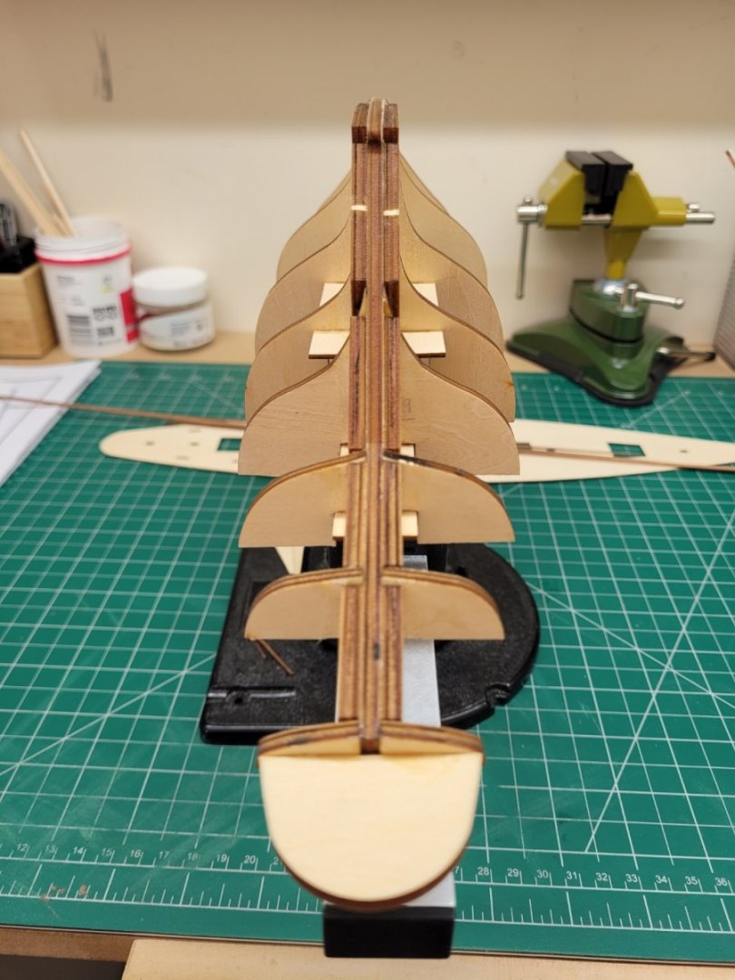
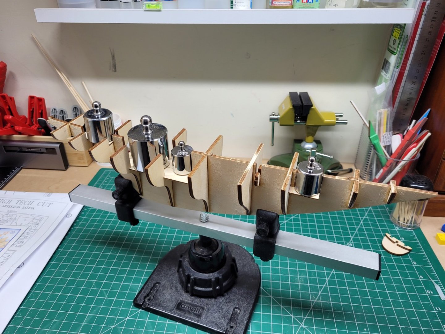
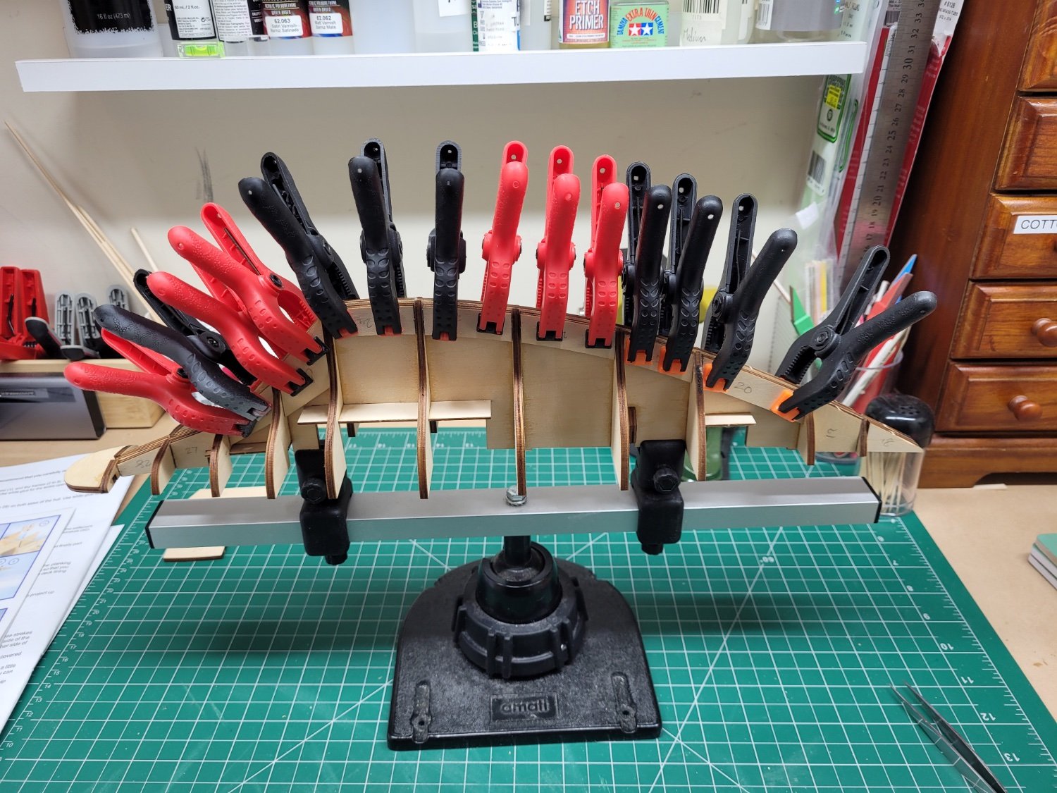
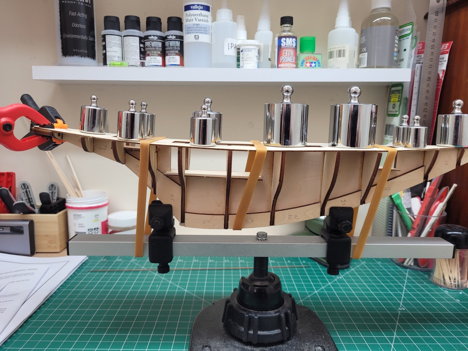
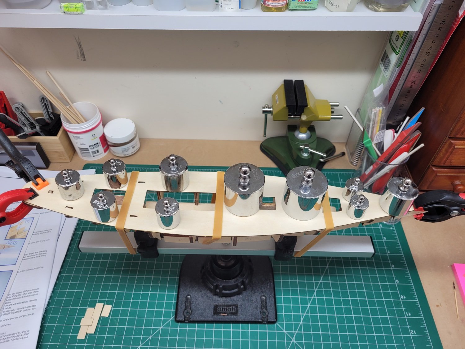
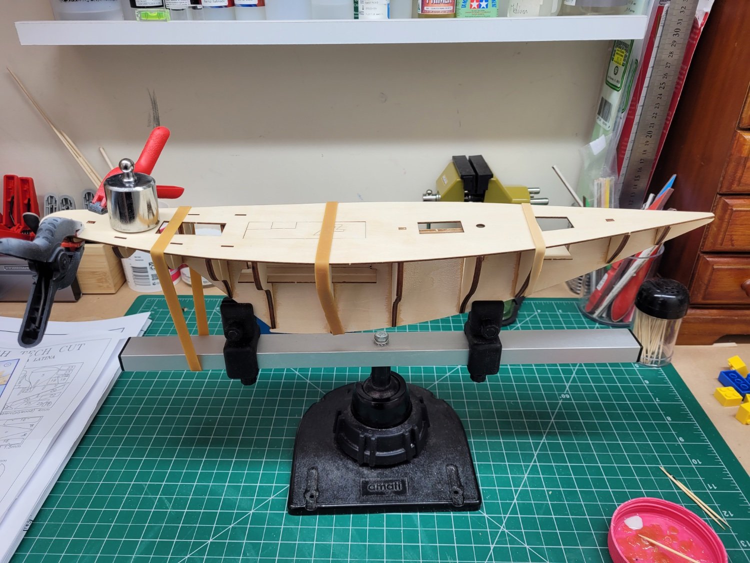
After planking the cockpit floor I then gave the top of the false keel a quick run over with a sanding block just to make sure the plywood deck would sit nicely across all of the frames. I used PVA glue on the frames and false keel and set the deck in place, securing it with elastic bands and small weights to ensure a good solid fit across all of the frames.


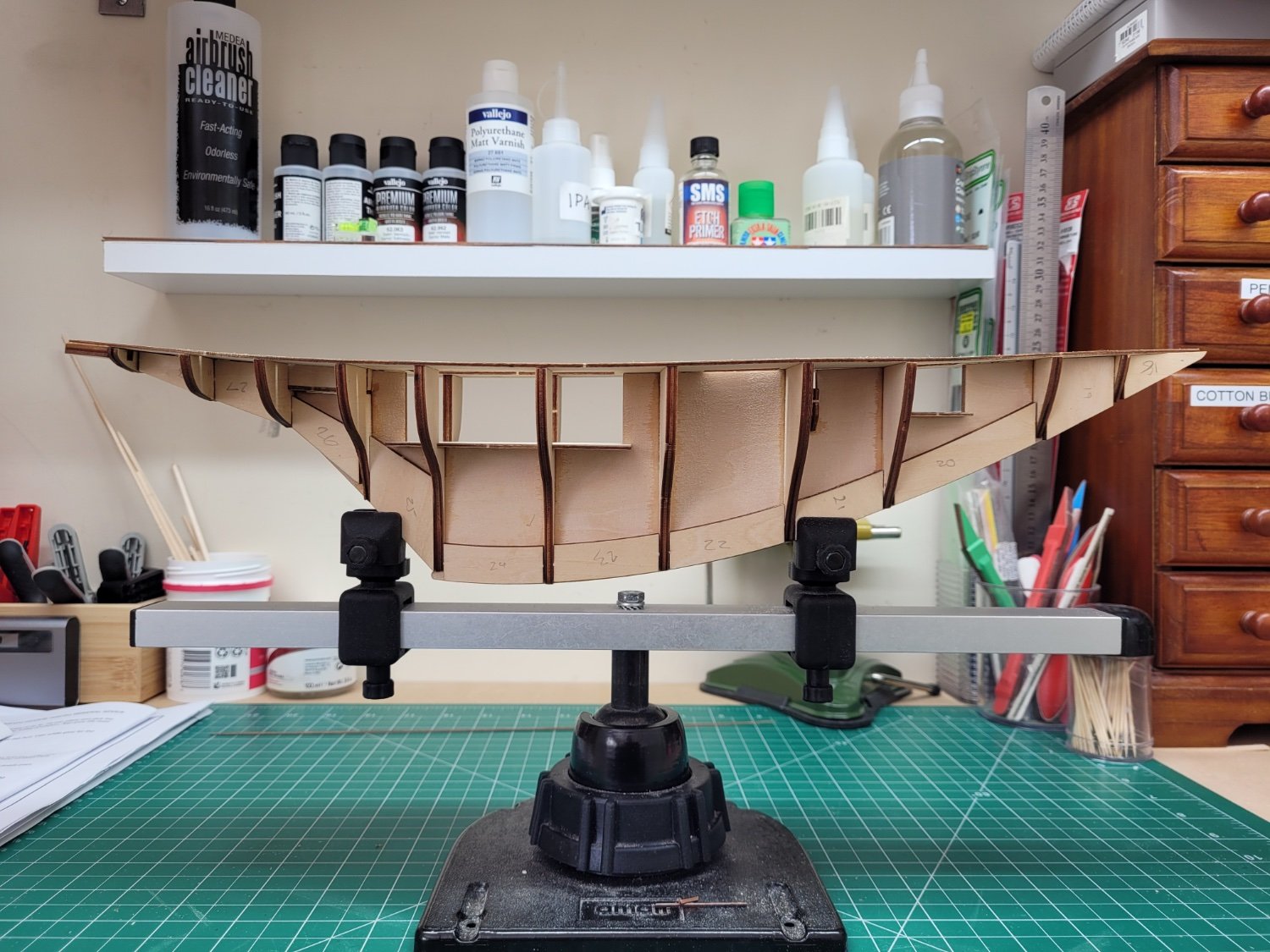
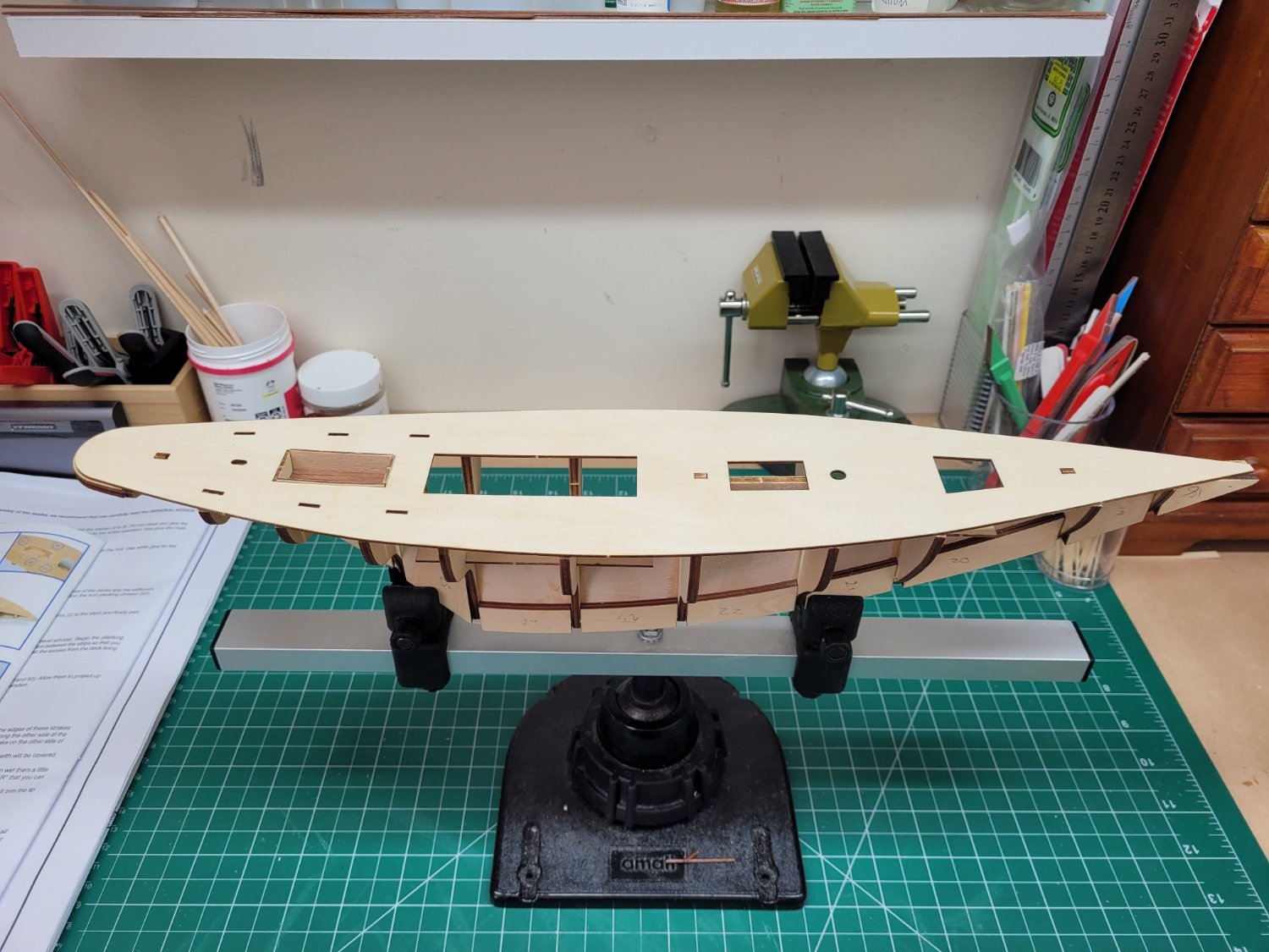
Finally, the walls of the cockpit were glued into place. All is now ready for fairing of the frames.

It may be a short while before I get the fairing completed as I can really only do this outside, which means I am limited to whatever spare time I can find at the weekends to work on it, but hopefully it will be done in the next couple of weeks. In the meantime I may be able to start on some other sub assemblies or having a trial go at the best way to approach the decking.
- Thukydides, BobG, Paul Le Wol and 6 others
-
 9
9
-
The pumps look great - that is a neat little enhancement !
- AJohnson, Thukydides and Diver
-
3
-
This looks like a very interesting build Denis. I will be very curious to see how you go about making the engine and installing all of the RC equipment etc as I know absolutely nothing about that myself and would be interested to learn more.
-
Well done Chris and James - another great kit!
- mtaylor, thibaultron, Oboship and 3 others
-
6
-
Artesania Latina do not number the frames and parts in the laser cut wooden sheets but instead they provide a small piece of paper with a diagram of the parts, so the first task is to number the actual parts in pencil so that things don't get mixed up when the frames are removed from the fret. The false keel and frames all seem to be nice and flat. Already the lack of detail in the written instructions is apparent as the first step guides the builder to remove frames 2 - 8 from the fret and then glue frames 2 - 13 to the false keel. Luckily the pictorial guide shows that you also have to remove frames 9 - 13 from the fret as well 😃.
The frame joints were all too tight to fit to the false keel correctly right away and so some minor sanding of both the frame slots and the keel was required. The slots for frames 2, 3 and 4 also needed deepening slightly so that the tops of the frames sat flush with the top of the false keel.
I then did a trial fit of the sub deck floor pieces 15, 16 and 17 and these were a good fit right away. The frames all sat nice and squarely against the false keel without any issues but I did hold them in place temporarily with some lego blocks whilst I glued them - this was done with some thin CA piped into the frame / false keel joints. At this point frame 12 and the stern under deck piece 13 have not been attached.
The mast support, part 14, was then glued in place along with the sub deck floor parts 15, 16 and 17.
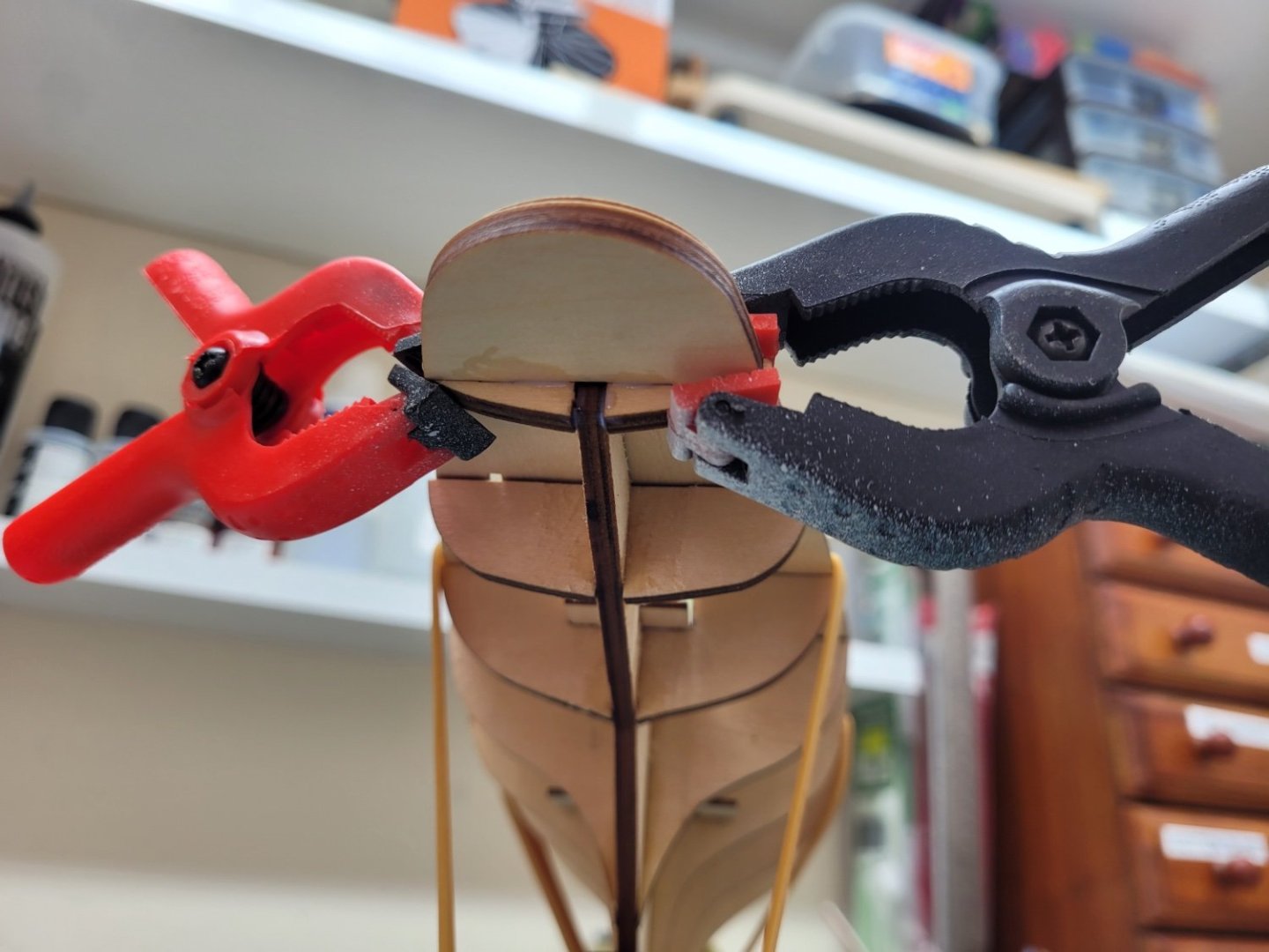
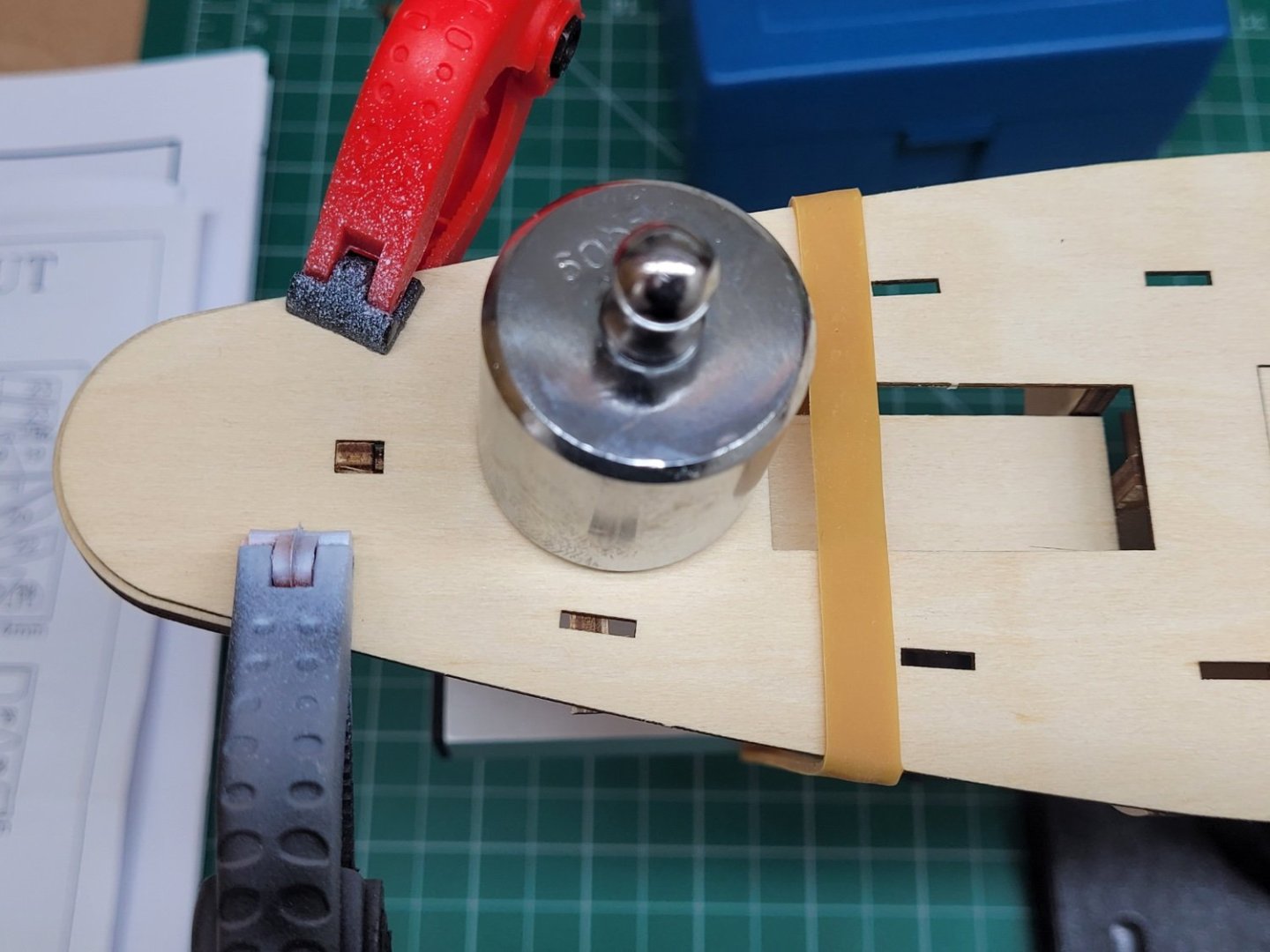
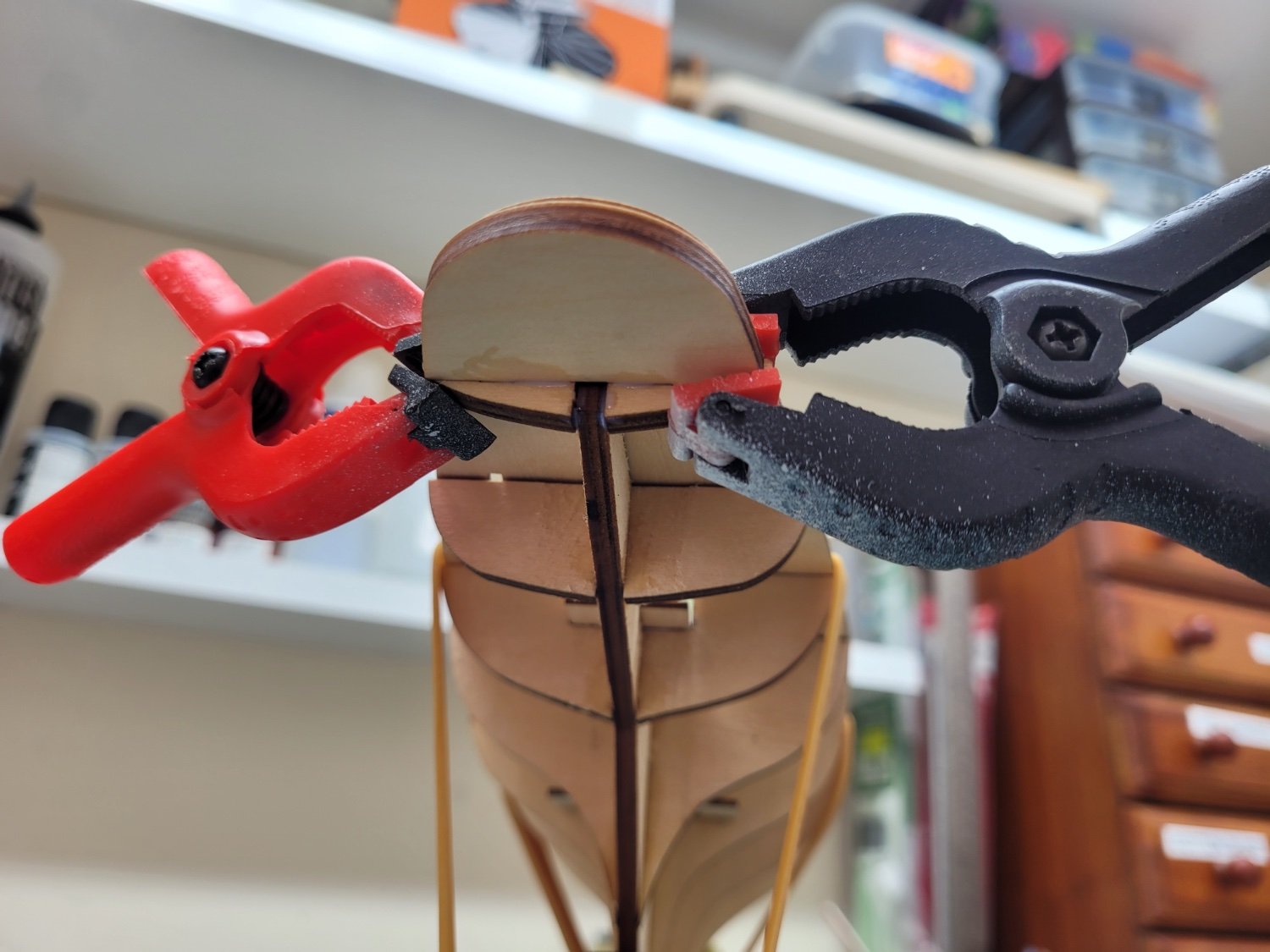
I then tried a test fit of the plywood false deck. There are three tabs on top of the false keel that fit into slots in the deck to key it into position. However only the front and middle slots easily aligned with the tabs and I had to trim a tiny amount off the back of the rear tab for it to sit properly in the rear deck slot. With the deck sitting on the frames, held down by elastic bands, I was then able to determine the position of the rear most frame, frame 12, and the stern under deck piece 13. There is a noticeable upwards curve of the deck at the stern so setting the angle of the rear frame and deck support in this manner ensure the sweep is nice and consistent. This was clamped in place whilst the glue set.

- goatfarmer11, BobG, Bryan Woods and 4 others
-
7
-
Thank you all for for the encouragement. Your build area is a lot cleaner and tidier than mine Thukydides!
- Thukydides and Bryan Woods
-
2
-
-
8 hours ago, DB789 said:
Your Alert looks superb, I wish you’d done a log too.
Thanks for the kind words. I wasn't sure I would have the time or ability to put together an interesting log so I'm afraid I never made the decision to start one. However, given how much inspiration and information I have received from reading other logs on MSW I have just started a log today for my latest build.
- AJohnson and Ryland Craze
-
2
-
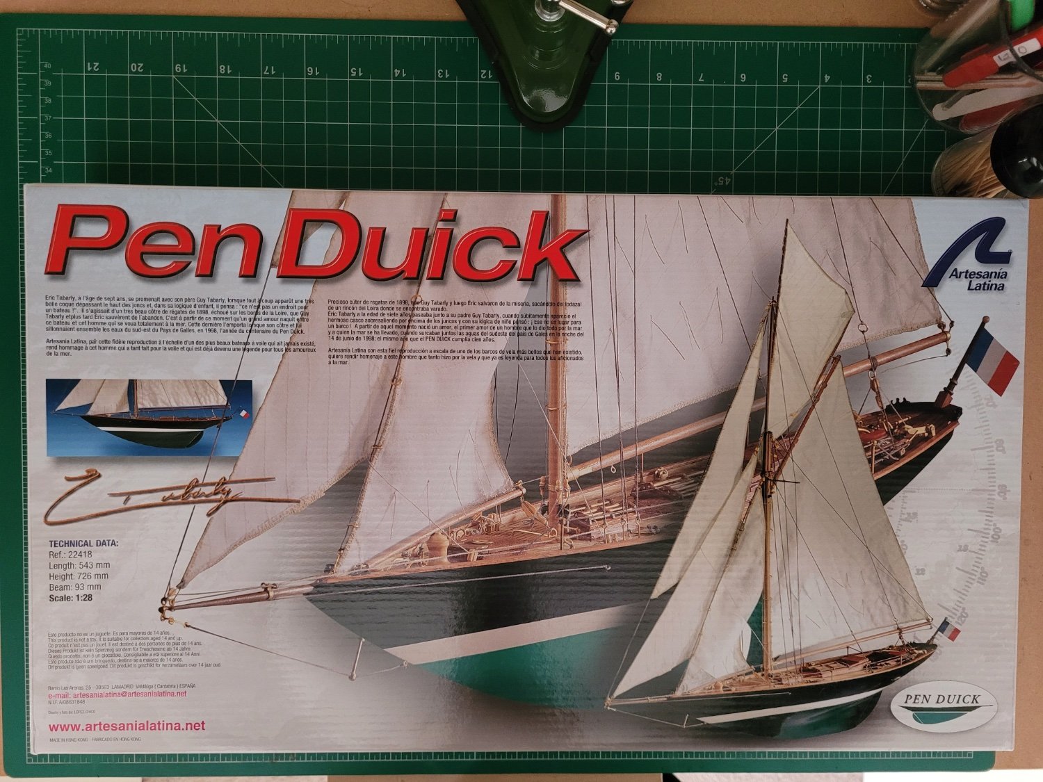
This will be my first build log on MSW so I hope I can provide something that may be interesting. As the title indicates this will be a build log of the Artesania Latina's Pen Duick. According to the article on Wikipedia, 'The YRA 36ft linear rater Pen Duick (formerly Yum) was designed by William Fife III and built in 1898 by Gridiron &B Marine Motor Works at Carrigaloe in Cork Harbour, Ireland for Cork yachtsman W.J.C. Cummins. The gaff-rigged cutter was quickly noted as a successful racer in Irish, British and French waters'. I like the fine lines and design of this historic yacht and decided to try a build of this type of vessel, and so hopefully I can do justice to this and end up with an attractive model. I have already received a lot of inspiration from the other build logs on this site and I will no doubt rely heavily on the work of @BobG, @hof00 and @Reci when progressing with this project.

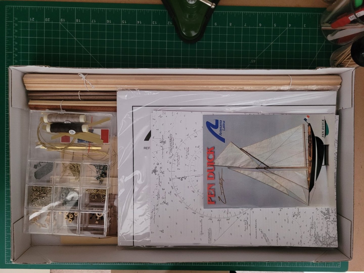
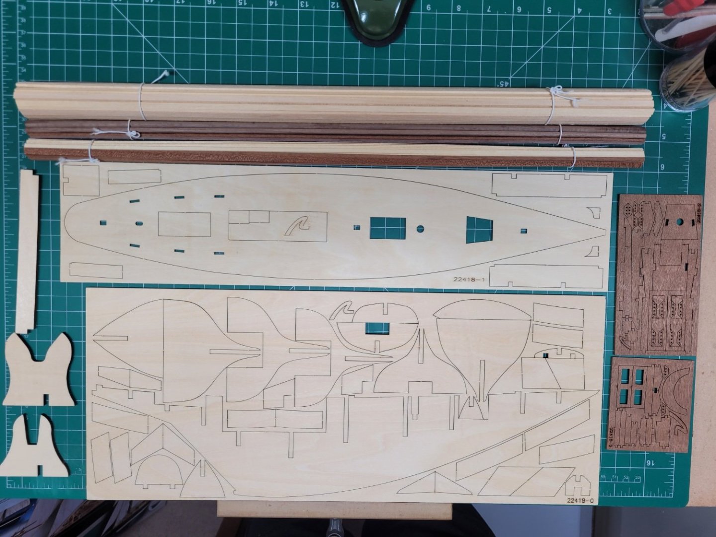
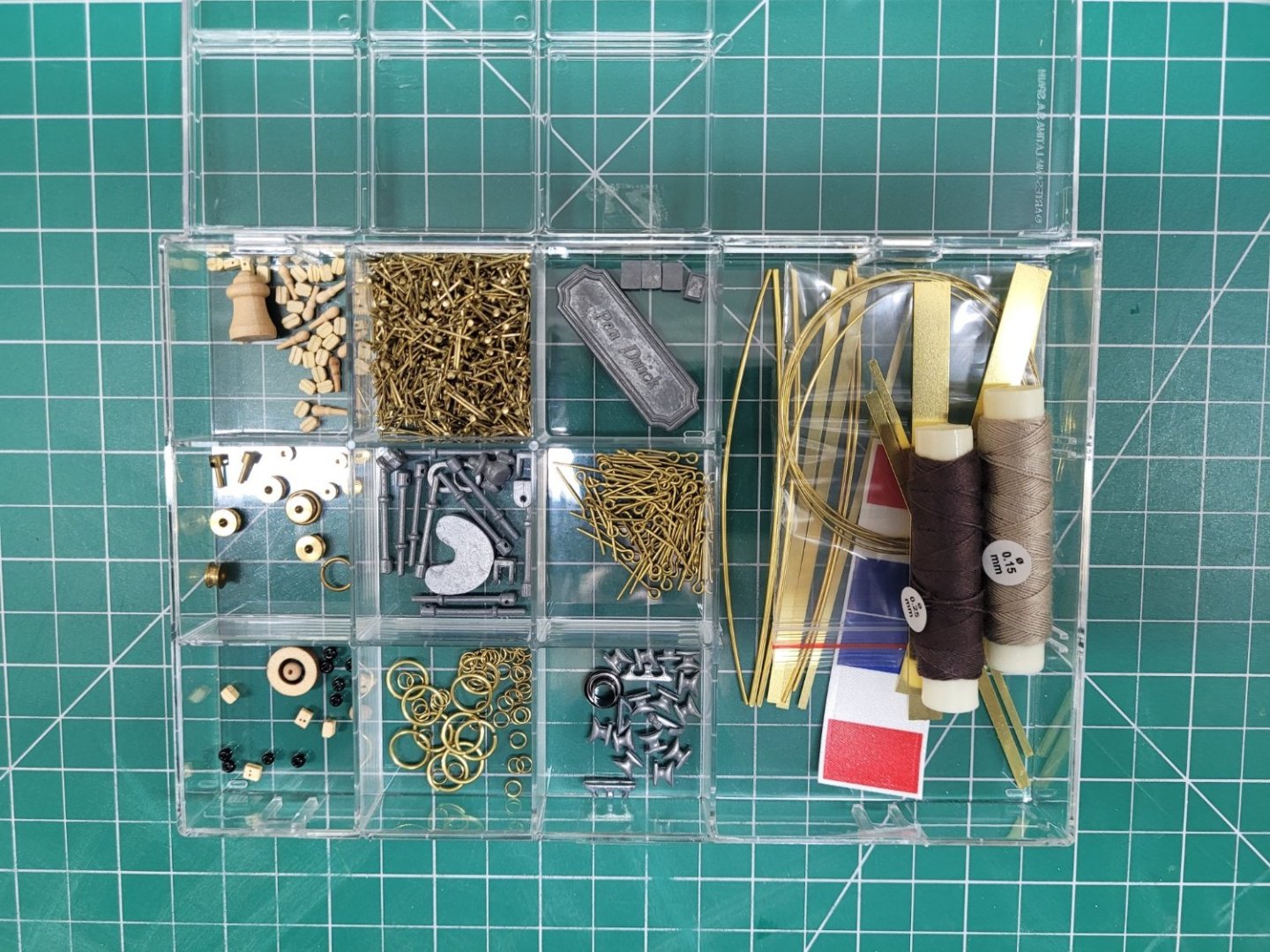
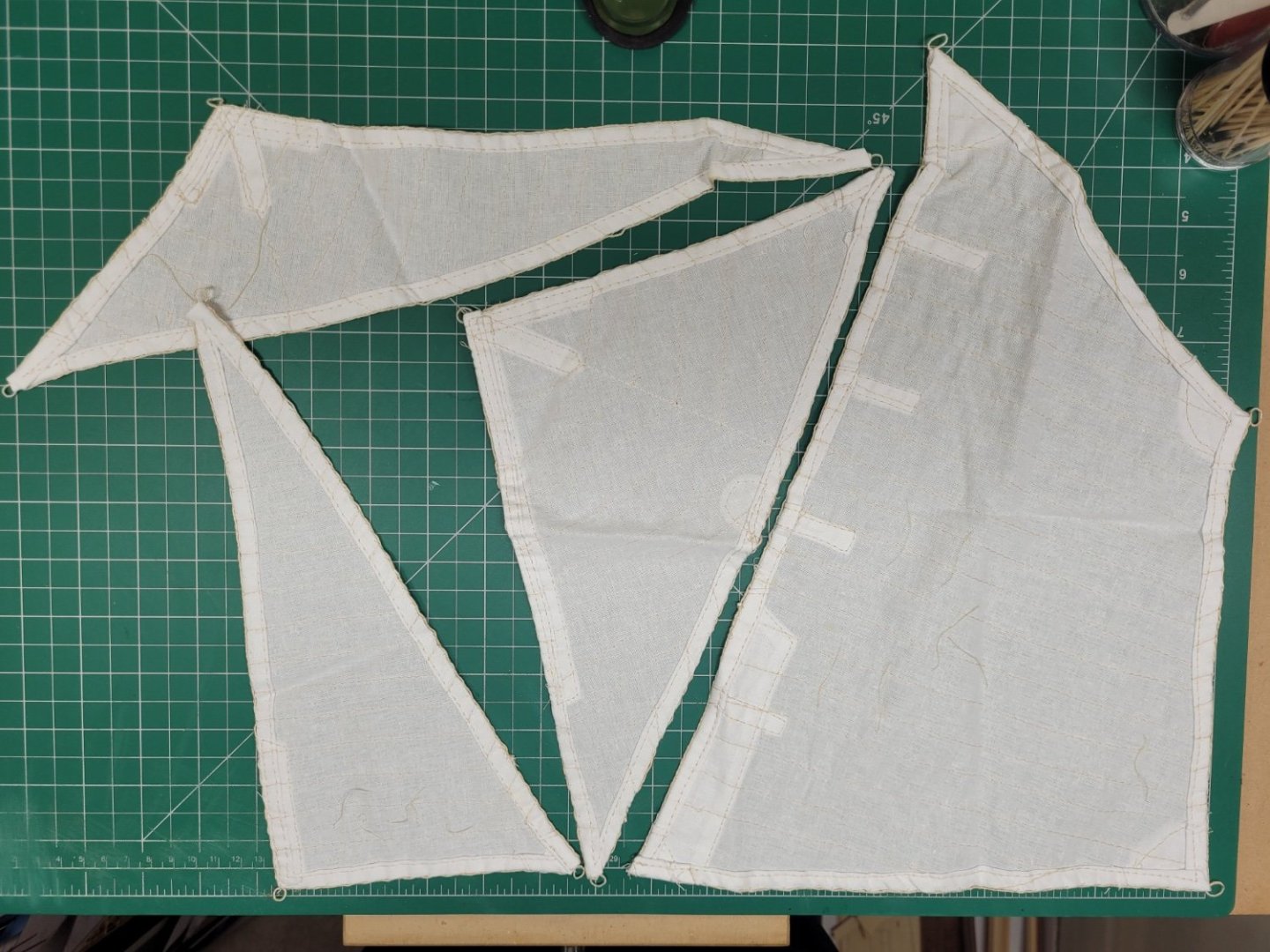
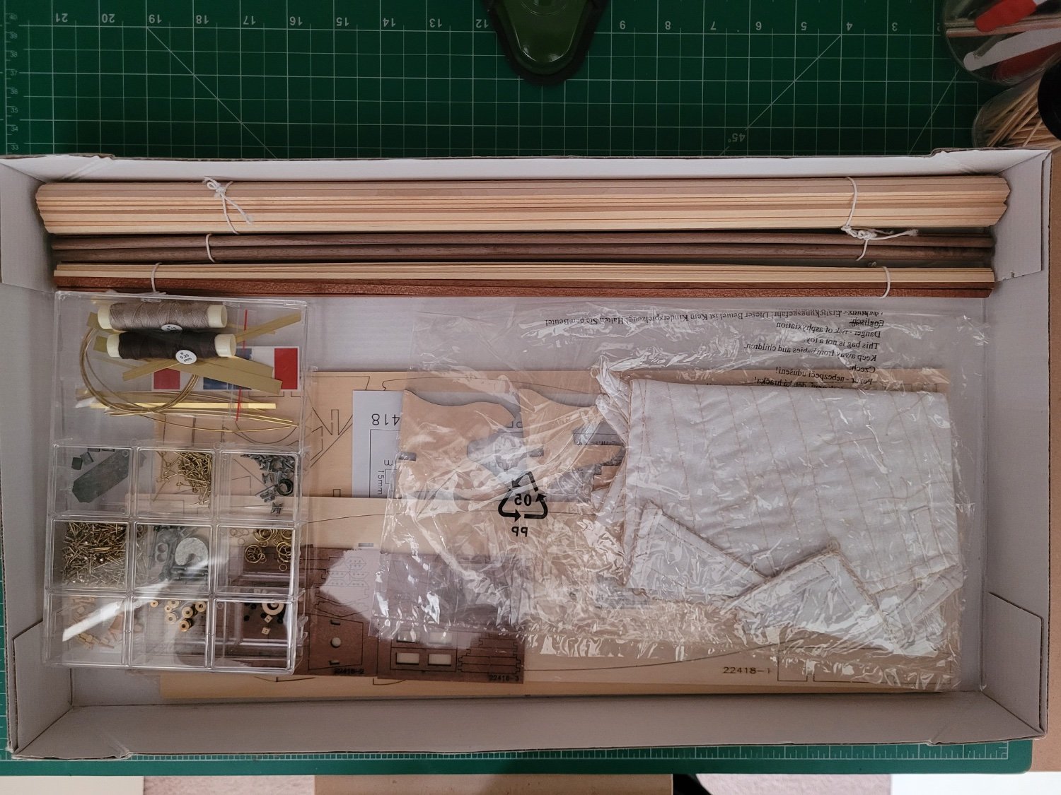
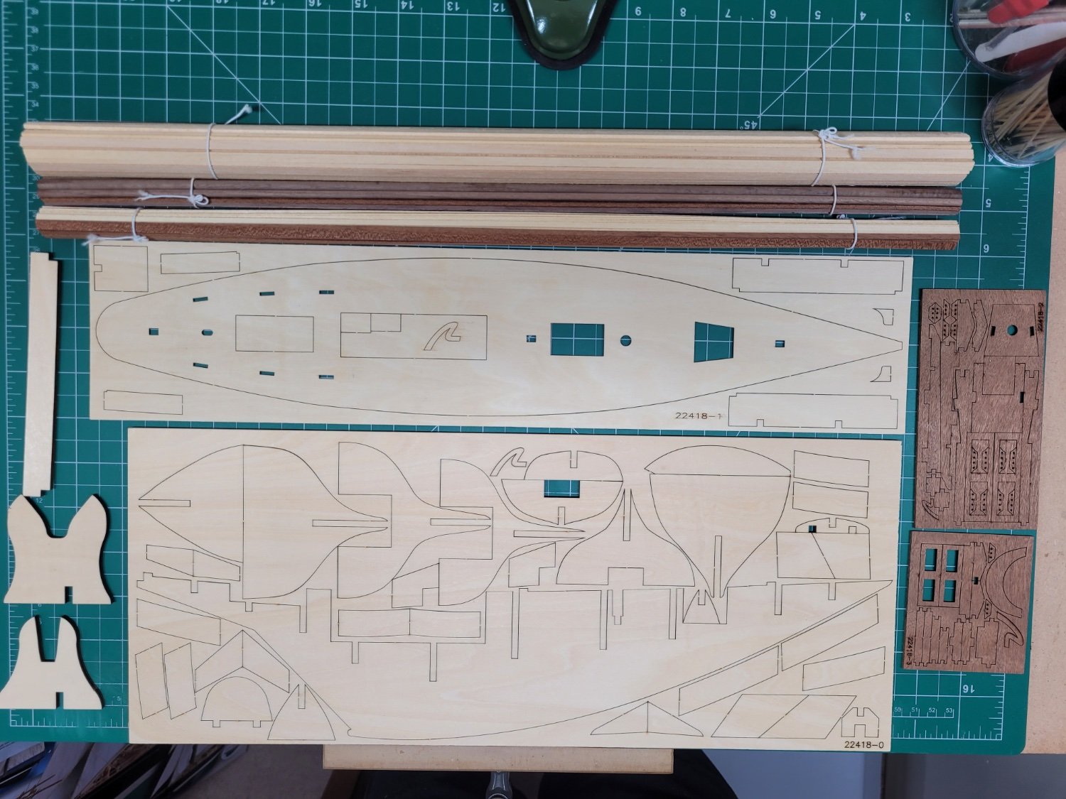
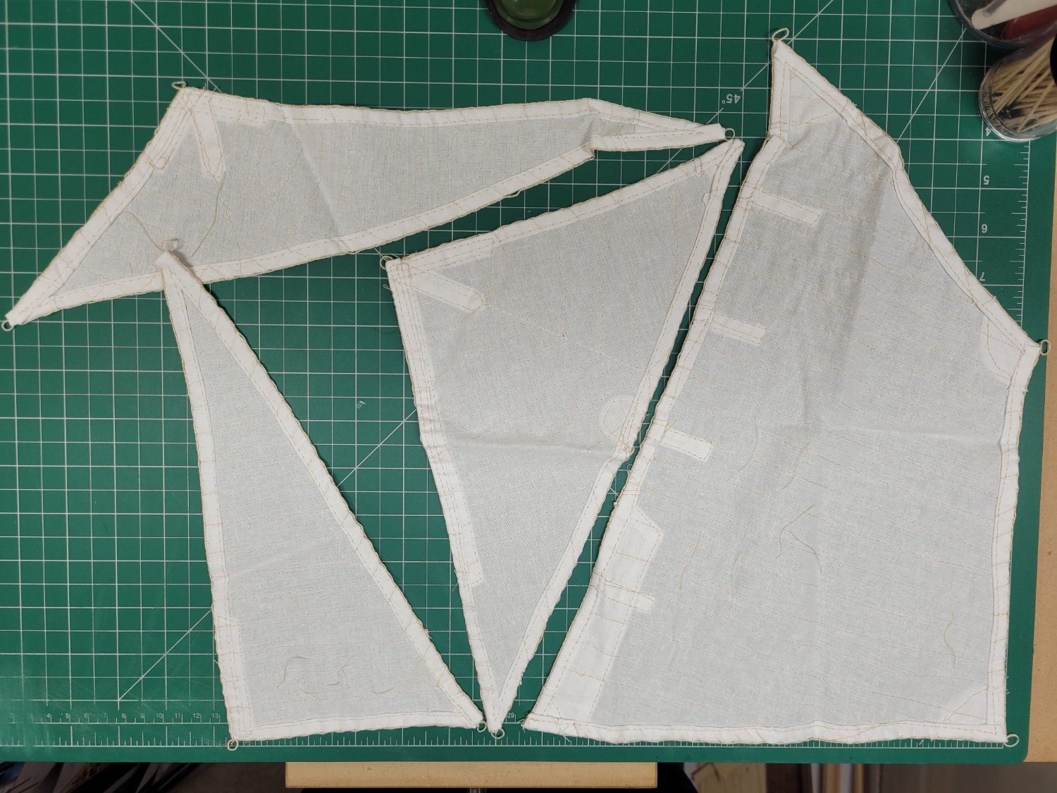
Here is a look at the kit. The kit comprises a plywood false keel and frames, and according to the pictorial guide a selection of basswood planking strips and some sapelli and walnut lasercut pieces and dowels. However, the parts list gives the woods as ramin, walnut and mahogany, so I'm not quite sure which to believe! (Or maybe they are just alternate names for the same thing?) There is also the usual collection of brass and other metal accessories in the familiar perspex box. The kit also comes with pre-sewn sails although a comparison of these with the plans show that they seem a little undersized. In my case they are also under represented, there are five sails needed for the rig but my kit only contains four! I am considering displaying the kit with sails which will be the first time I have tried this but that will be a long way down the track so I will see how things are going before deciding later on whether I have the skills to make my own sails.

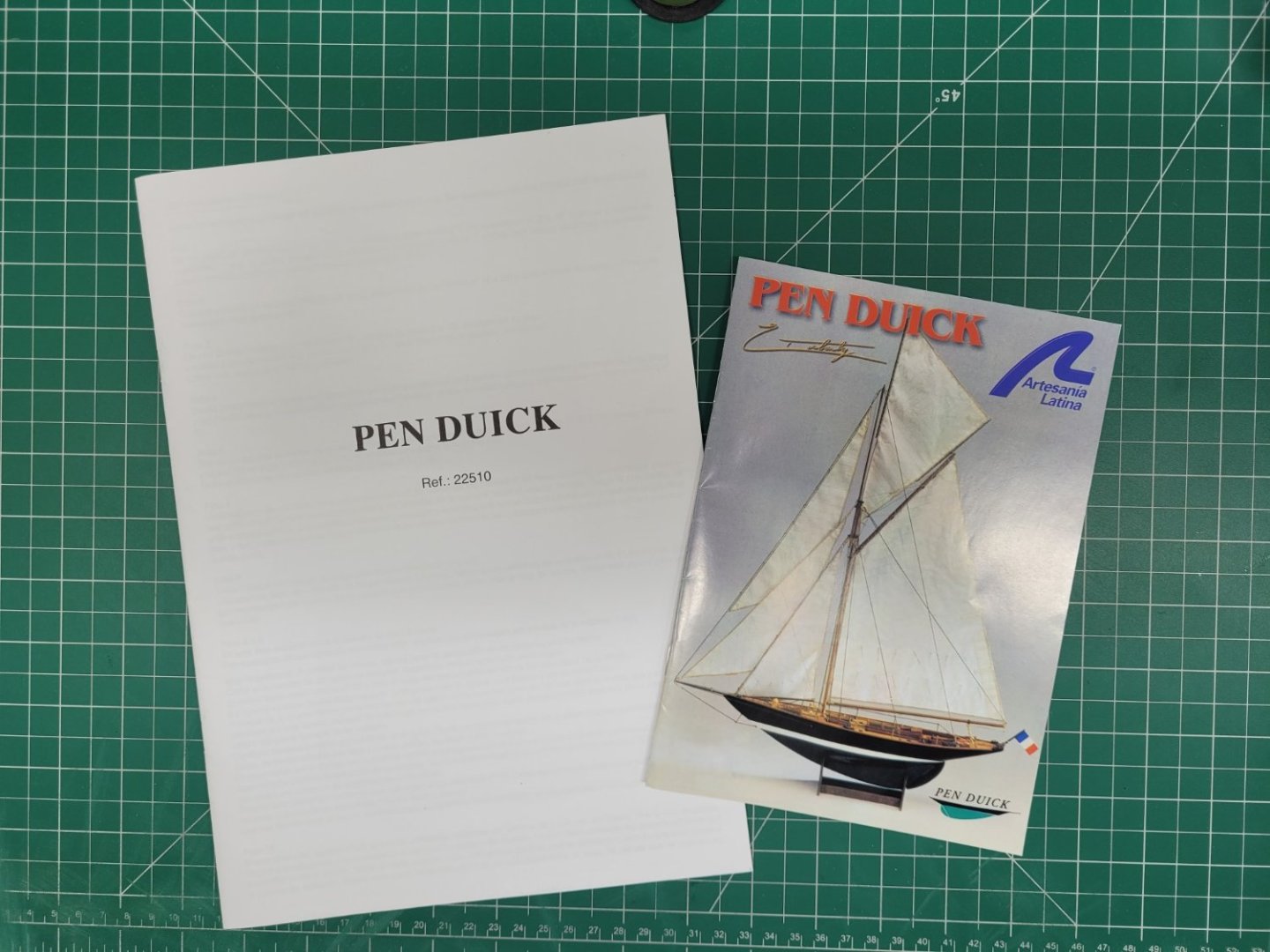
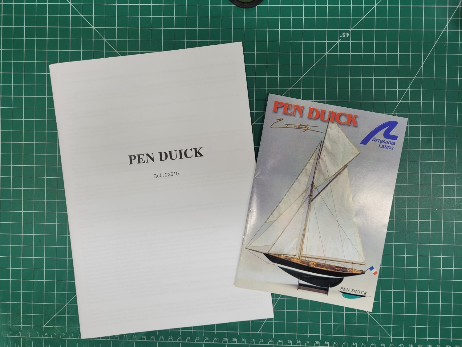
The kit comes with a leaflet of instructions in a variety of languages, a pictorial build guide and two large double sided plans. The plans detail the sail templates and a rigging plan on one sheet and a full sized profile and deck plan and mast and spar plan on the second sheet. As with many of the older Artesnaia Latina kits, the instructions are pretty basic, only one and a half pages of text for the whole build. Having come from building some of Chris Watton's fabulous Vanguard Model ships with their impressive manuals this will be something of a challenge again. I have built a previous kit from Artesania Latina though so if I was able to do that then I am sure I should be able to manage once more.
I have bought a few items as upgrades to the kit offered accessories as the Artesania Latina components are not the best in the world. I have some blocks from Vanguard Models and rigging line from Syren. I also have some alternate strips available for planking as the kit provided ones are 2mm thick which may perhaps prove tricky to bend appropriately - I have some 1mm limewood planks which I may use.
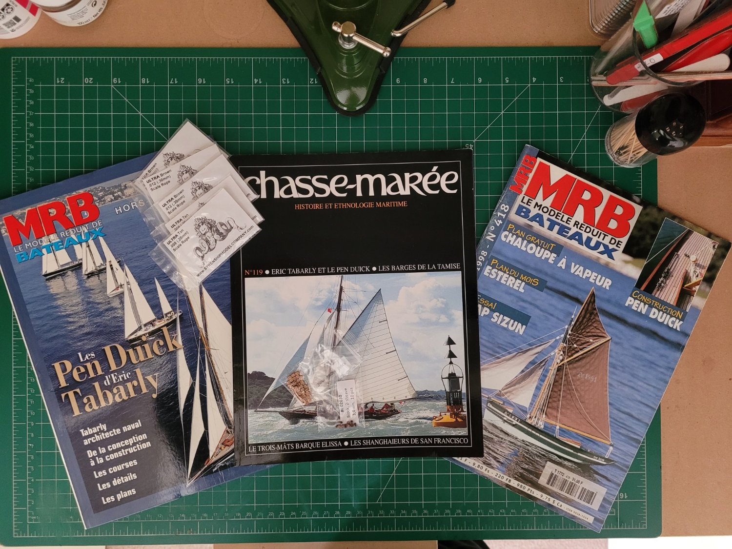
Thanks to the information in @BobG's log I have also been fortunate to collect a few resources to help with the build. These include a few French modelling and sailing magazines with useful articles about the Pen Duick and her history. There are also a lot of images available online which will help with the details of the deck fittings etc.

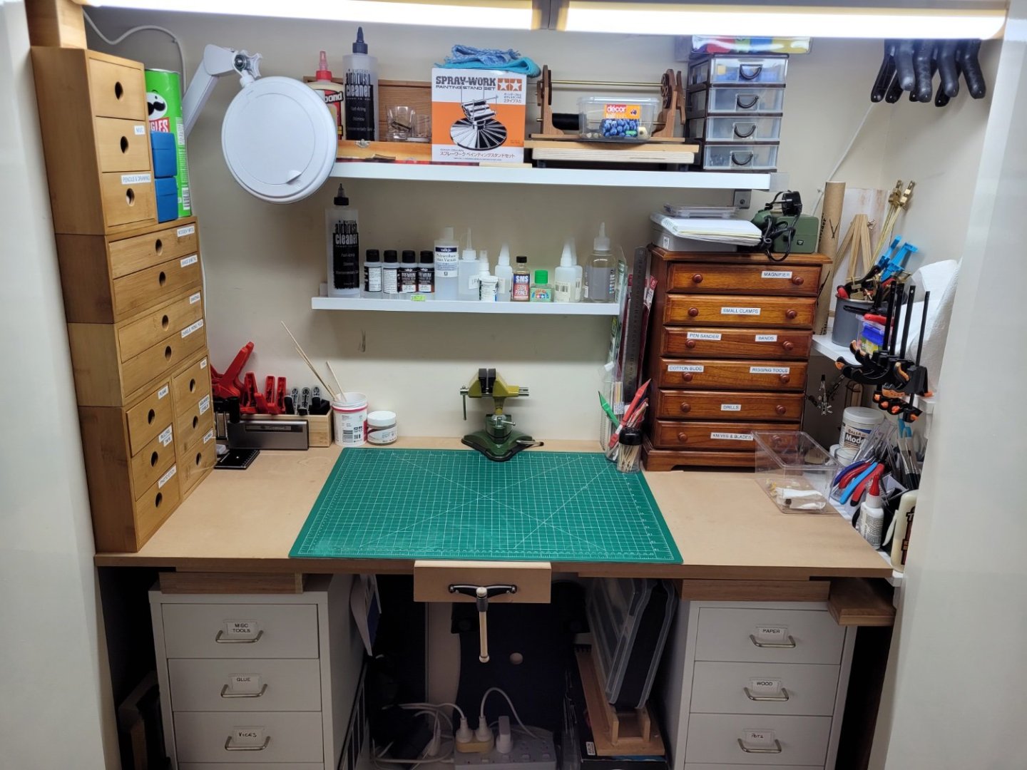
Finally in this first post I thought I would also show my build area. This is in one of the spare bedrooms and is actually one half of the wardrobes - do many other modellers on this site work in a cupboard? Despite its size limitations it is actually quite convenient because when I am done for the day I can simply shut the doors and everything appears nice and tidy. It is therefore convenient sometimes to just to spend 20 minutes or so working on a particular part of the build and not have to worry about getting everything out and setting up a work area elsewhere in the house. On the downside the bedroom carpet has claimed an awful lot of small parts which find their way onto the floor!
Oh, I'm also not a particularly quick builder so this may not be a log with regular updates but I will try to do my best to keep things ticking along!
- goatfarmer11, Thukydides, Reci and 9 others
-
12
-
Magificient. This is absolutely fantastic!
- billocrates, mtaylor and Mr Whippy
-
3
-
The mizzen mast isn't included in the kit but you can make one from scratch and store it on the deck like Blue Ensign did in his build. The Alert book does give a diagram of the mizzen mast and its yard but I decided not to make them for my model just to keep it less complicated. My reasoning was if I make the mizzen and yard should I then also make spare yards for the main? And then what about the cutter and longboat and mounting them on the deck? (I am making the cutter separately to display but not on the deck).
If you do want the dimensions for the mizzen and yard I can look them up for you.
- Thukydides and AJohnson
-
2
-
Thanks. That's a really interesting guide on how you add detail and depth with your painting.
- Thukydides and Obormotov
-
2
-
Hello. Looks like your build is coming along nicely. I had to add a plank under the transom piece in my build as I also had a bit of a gap there which was making the sternports a little too low.
- AJohnson, Thukydides and KARAVOKIRIS
-
3
-
Welcome !
- Keith Black and mtaylor
-
2
-
Yes, there are a few extra parts of various things in the kit to allow for breakage, or in my case dropping stuff on the floor and never finding them again
- Thukydides, Obormotov and Peanut6
-
2
-
 1
1
-
-
Looking good. It may just be the angle of the photo but you may perhaps need to take a little more off at the stern to account for the depth of the second planking so that this lies flush against the width of the stern post.
-
I have a couple of these little boats to make soon so this part of your log will be very helpful to me 👍
-
Congratulations - it is excellent workmanship
- druxey, Seventynet, Keith Black and 1 other
-
4
-
Hi Seventynet,
This is a fabulous build and it is really encouraging to me that you are a first time scratchbuilder. My copy of David's Hayling Hoy book is due for delivery tomorrow so this will hopefully be my first scratch build too at some point in the future. Your log will certainly serve as inspiration and guidance for me!
- VTHokiEE, billocrates, Seventynet and 1 other
-
4
-
-
Yes I am having the same sort of problem with browser bookmarks so I may give an adaptation of your system a try. Thank you very much.
-
That is an interesting way of storing references to different parts of other build logs - something to ponder 👍
-


Pen Duick by jpalmer1970 - FINISHED - Artesania Latina - 1:28
in - Kit build logs for subjects built from 1851 - 1900
Posted
Hi Bob,
I need you to rig yours so that I'll know how to rig mine! 😄