iMustBeCrazy
-
Posts
958 -
Joined
-
Last visited
Content Type
Profiles
Forums
Gallery
Events
Everything posted by iMustBeCrazy
-
 Yes, putting a shed over it was a step up from this:
j7815gc.jpg.8a52d1e5b230d470dcfc3fadfe03d53b.jpg)
-
She's moving along Tim. Something looks a little off aft, possibly the angles? Also, note that the drawing has the W.C. and pantry too far forward. Cheerful could be a reasonable guide, https://syrenshipmodelcompany.com/revenue-cutter-cheerful-1806.php chapters 6-8.

-
I just found this in the Danish archives:
-
DIY Mini Plane
iMustBeCrazy replied to iMustBeCrazy's topic in Modeling tools and Workshop Equipment
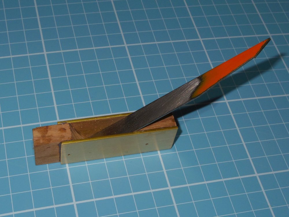
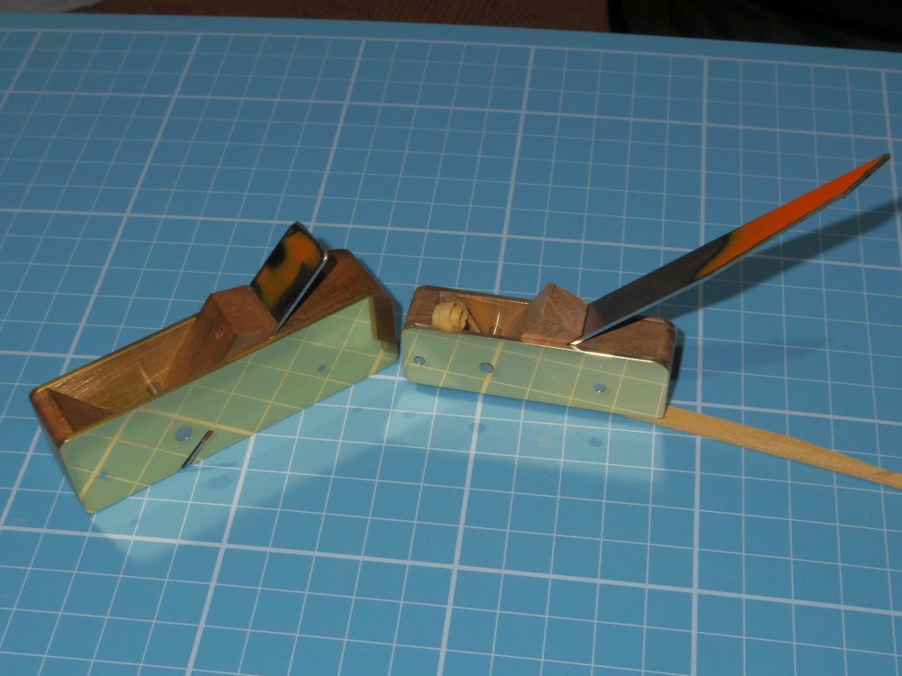
A couple of additions, an (almost) all wood version and a honing guide. I think that's enough planes for now.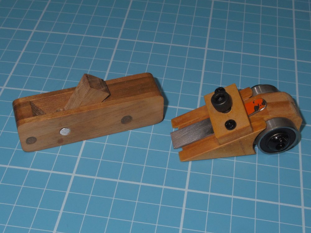
-
They will be tiny, what's 1/24 of say 3/4 of an inch?
-
Best way is to go to https://commons.wikimedia.org/wiki/Main_Page and type in your search, say "rmg frigate plan" and you will get https://commons.wikimedia.org/w/index.php?search=rmg+frigate+plan&title=Special:MediaSearch&go=Go&type=image Select image size large and you will get (mostly) the larger scans. You can modify your search using the modifiers AND and OR or even NOT (in caps)(the AND is usually implied) such as "rmg frigate plan 1812 OR 1813 OR 1814" [which is the same as "rmg AND frigate AND plan AND (1812 OR 1813 OR 1814")]
- 33 replies
-
- 1
-

-
- Bounty Jolly Boat
- Artesania Latina
- (and 1 more)
-
G'day Seb, it seems they've finally dropped the claim that this was 'the famous boat...'. As to what it is, it's probably a generic 20'9" longboat, it doesn't really matter just enjoy the build. How were ships boats painted? It probably depended on how much paint of what colour they had on board. For the Bounty all we have is "Hauled the Launch up and breemed her and payed the Bottom with half pitch half Tar." and "Paid the small Cutter with Turpentine having not sufficient white to do it." Payed or Paid meant Painted. So my guess is Bligh's boats were painted white but I have no idea how much of them was white. If you want to read more about Bounty's boats, see my sig.
- 33 replies
-
- 3
-
-

-
- Bounty Jolly Boat
- Artesania Latina
- (and 1 more)
-
I do sometimes think "on my boat I'd do it like this". And then do it my way. Probably in the corner of the knee, like this: I would also keep the tiller just above the transom so the horse isn't too tall, put a slight bow in the horse and bend it's 'legs' so that it is vertical above where it goes through the knee. But that's just how I'd do it.
- 66 replies
-
- 1
-
-
- 18th Century Armed Longboat
- Model Shipways
- (and 1 more)
-
It doesn't make sense to anybody. However, the Medway model shows a horse barely above the seat. This can be a very puzzling hobby.
- 66 replies
-
- 2
-
-
- 18th Century Armed Longboat
- Model Shipways
- (and 1 more)
-
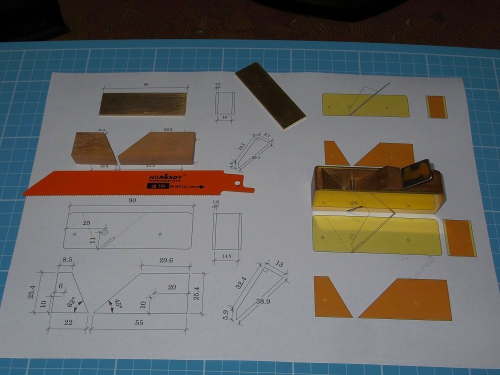
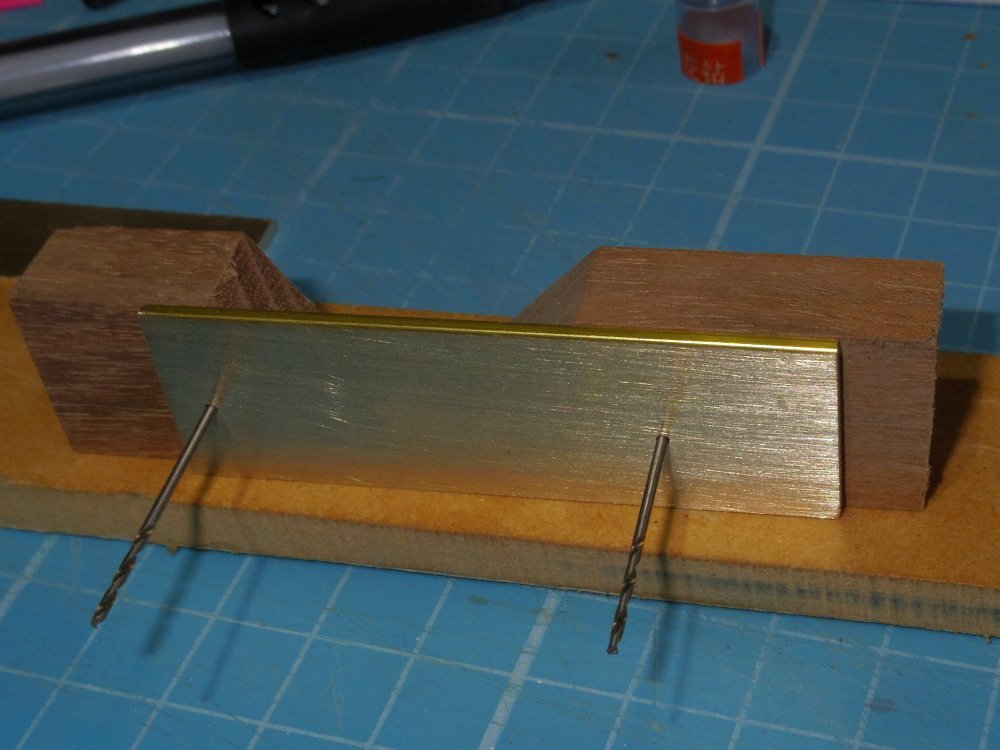
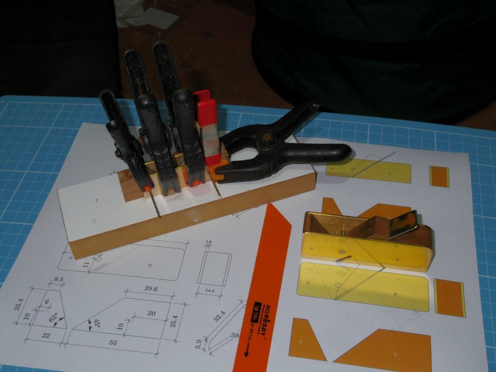
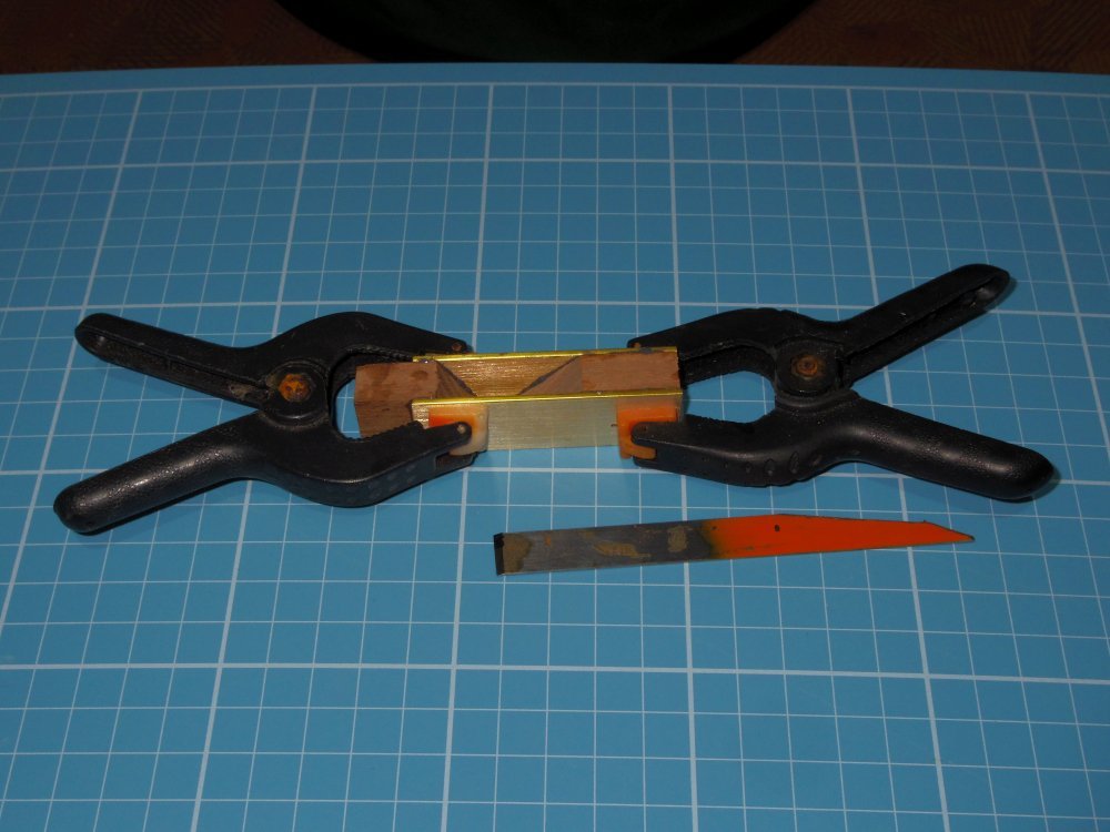
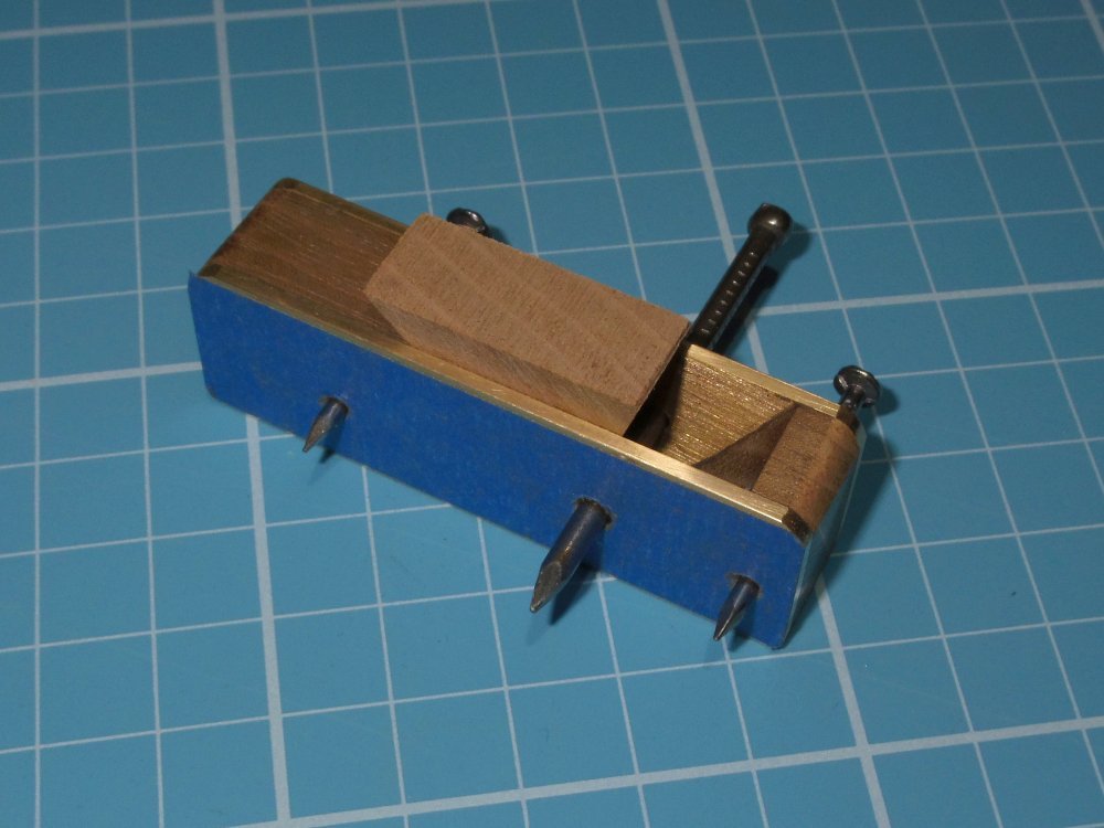
A few weeks ago I made myself a mini plane, it's 80mm long which fits nicely in my hand, has brass sides and I made it with a 'T' shaped blade (or iron) which, at the cutting edge, is the full width of the plane. But this meant that I couldn't use it as a shooting plane. So I decided to make another smaller which could. Parts list: Hardwood (something hard wearing that makes a nice 'clack' when you hit it), brass strap, three nails (two roughly 2mm diameter and one roughly 3mm diameter), epoxy glue and hardened steel for the blade (I used a reciprocating saw blade). Tools: Wood saw, Hacksaw, Drill, Drill bits the size of the nails, Hammer, Sandpaper (various grades), an Angle Grinder with 1mm thick disk and something to act as an Anvil. But I admit I also used a band saw and a disk sander. First, dress your wood to the required size but make it about twice as long as your finished plane. I my case 10x19x120mm. Cut out the template from the plan and glue it about the middle of the wood. Drill the two smaller holes. You will need either two drill bits for alignment when glueing or you could use the nails. Cut the 62 and 45 degree angles, trying to keep the 45 as square to the sides as you can. Cut the brass to size, glue the template and in one piece drill the small holes with the same drill bits used for the wood. Test fit as below. Mark the end of the brass on the long piece of wood (the one with the 45° angle), cut it to length. Do not cut the short piece until after glueing. Epoxy the drilled side to the two pieces of wood using the drill bits to align them and a flat surface to align the base, epoxy the other side using the back edge to align. While drying, cut the blade to size and sharpen it. I used 25° After the glue has cured, drill the holes through both sides, countersink the holes slightly, cut the nails to the overall width plus 2mm and make a wooden spacer 1mm thick with a hole in the middle slightly larger than the large nail (say 4mm). Now you need your Anvil, something solid with a hard surface, could be the back of a vise (not the jaws) or a small steel plate on a rock. Place the wooden spacer on the anvil, place the plane on the spacer with one nail through the hole, peen the nail so that it fills the counter sink, turn the plane over without the spacer and peen the other end of the nail. When peening the large nail, use the offcut saved earlier to keep the brass sides from bending. Sand both sides of the plane until the nails are flush with the brass. Generally sand the plane to soften edges and corners, make it nice. Cut the wedge to size. On a cutting board, fit the blade, fit the wedge and tap it in firmly. To adjust the depth of cut tap (quite hard) the front of the plane for a deeper cut or the back of the plane for a shallower cut. Fin. Mini Plane.pdf
-
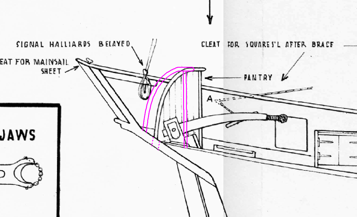
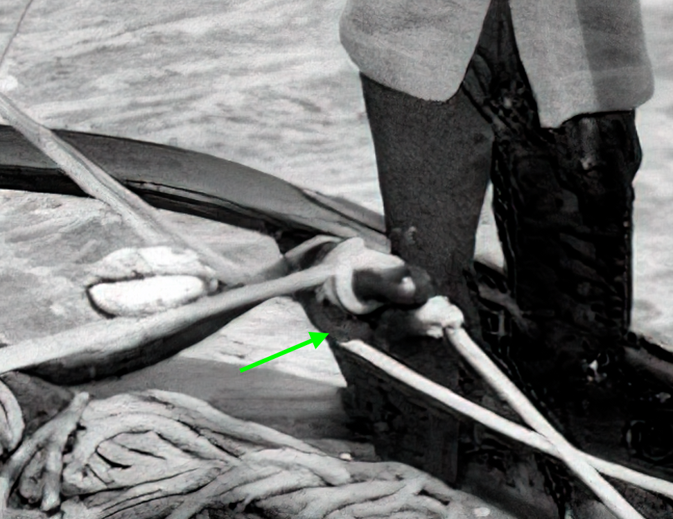
Allan, I'm embarrassed. I know I've seen round foot rails depicted before, I thought in Pinnaces or Barges, but this morning I can't find any examples. I'd say Chuck's nailed it except in this case it seems to be set up for two positions. Also note the round foot rail for the aft thwart in this enlargement. Drat, the forum re-sized it.

-
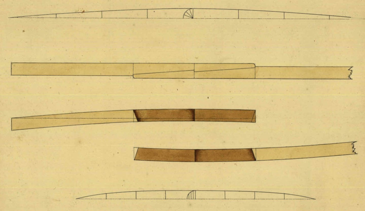
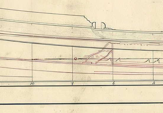
Actually they both did. The drawings in Allan's first post show the deck of Bristol (with scarphs) and the profile drawing of Portland (also with scarphs). Here's some more drawings: Now, here's an interesting one, Stirling Castle has no deck beam timbers longer than about 24 feet. Where 24' is sufficient for a scarph joint one is used, if 24' is not long enough a chock is used instead. Unfortunately the profile drawing doesn't show any joints.
-
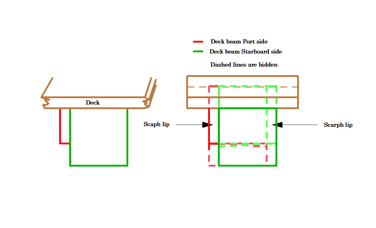
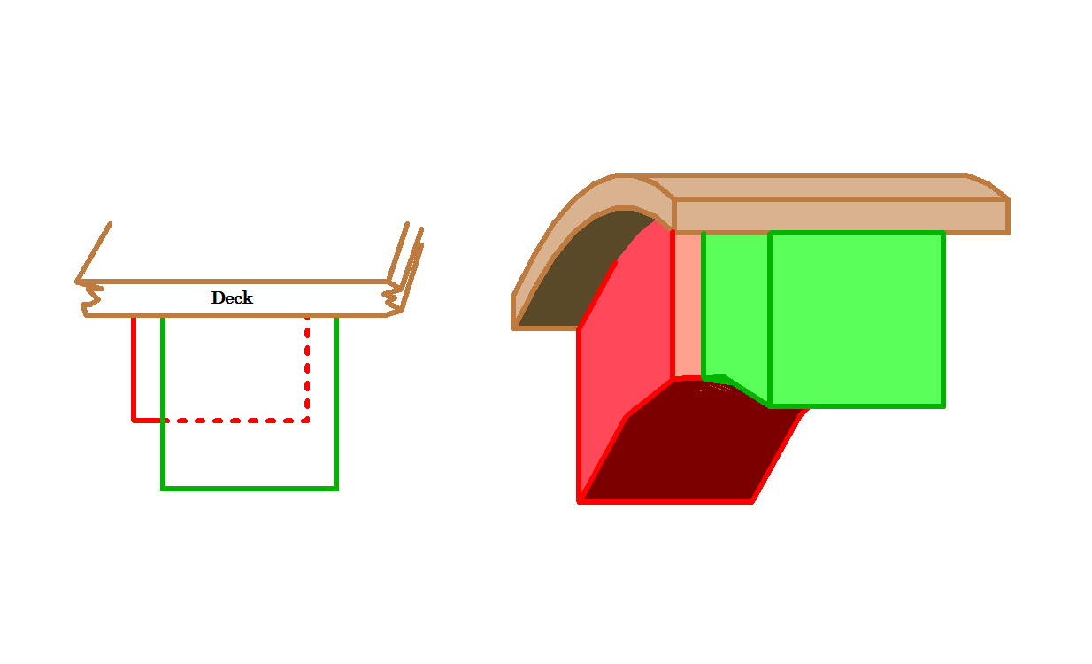
For what it's worth, I agree. This is what is depicted (not to scale):

-
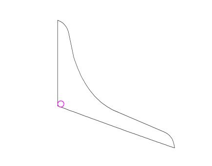
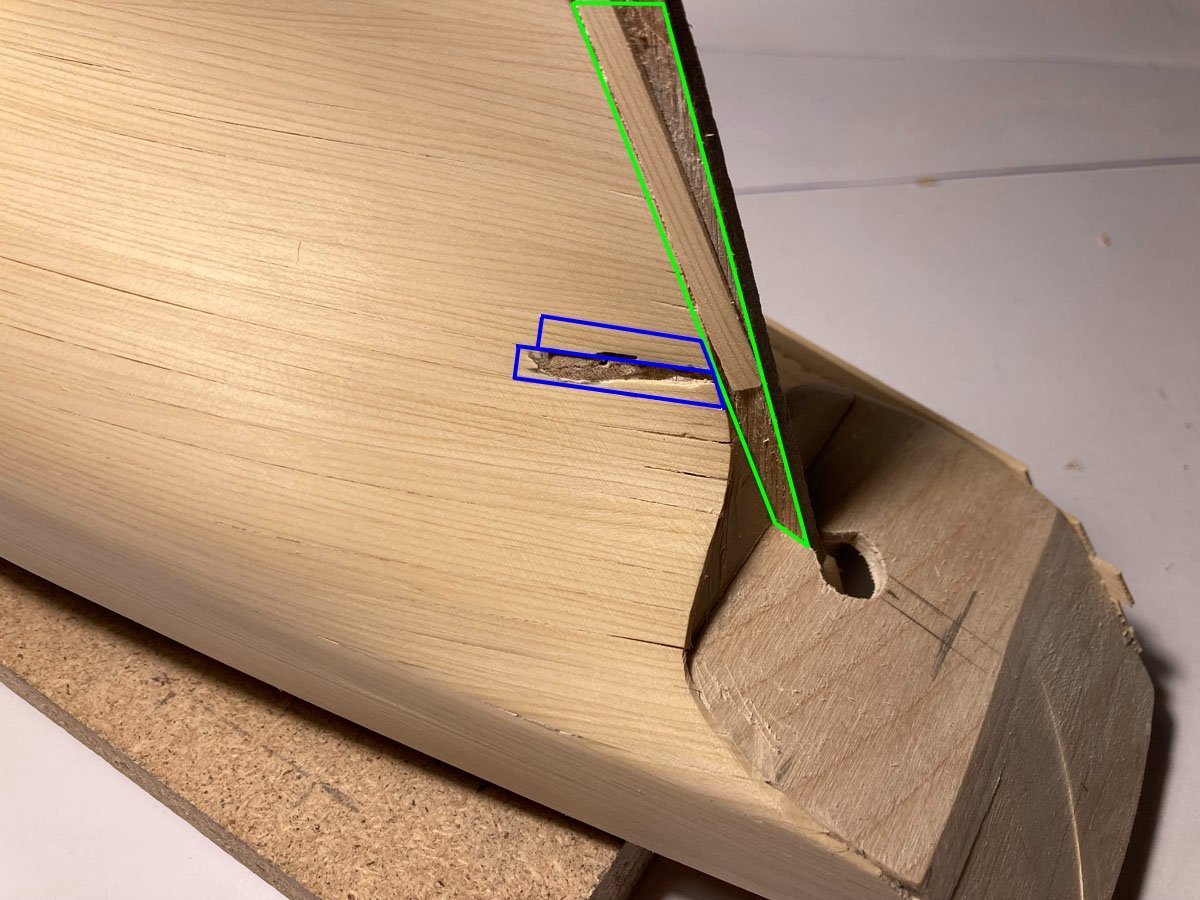
It's wood and you're only really worried about the outside surface, it's repairable. Carve out the areas in purple until almost the depth of your planking, select wood with matching grain and glue in (clamp with your thumb if you have to), sand lightly. Remove the plank from the stern post and do it all in one piece (edge glue 2 or more pieces to make a broad plank if you have to). I think it will look better if the grain runs parallel to the aft edge but choose what pleases you.
-
I think the big issue here is Chinese piracy, if these plans were easily available I have little doubt they would be cloned. That said, there is more than enough information in the instructions to build the model. Add in the numerous build logs and have at it.
-
How do you think I feel? I worked this out months ago and then forgot
-
Thanks Tim, I've seen the second but not the first.
-
BINGO! I knew that....once.
-
I think the last block is just hidden in the shadows.
-
Flotherwoode seems to be fake wood grain. Queen Elizabeth employed Leonard Fryer to decorate the long gallery at Oatlands with a woodgrain pattern in 1598. He primed the panelling with white lead paint and then painted imitation "flotherwoode", with gold and silver highlights on the mouldings, with arabesque patterns and paintwork of "markatree", perhaps resembling marquetry. So, ornate paintwork seems to be the theme.
-
Seems to be "Royal Navy Captain, 1805" by Alexandros Models (whoever they are http://www.alexandrosmodels.com/).
-
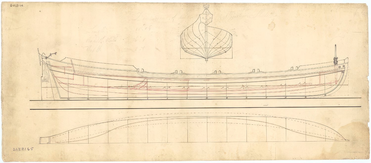
Again, I think there were more exceptions than rules: https://www.rmg.co.uk/collections/objects/rmgc-object-535332
-
Which is a copy of HIL210 from the RMG. This is a drawing by a shipbuilder not the Admiralty which might explain some differences.
-
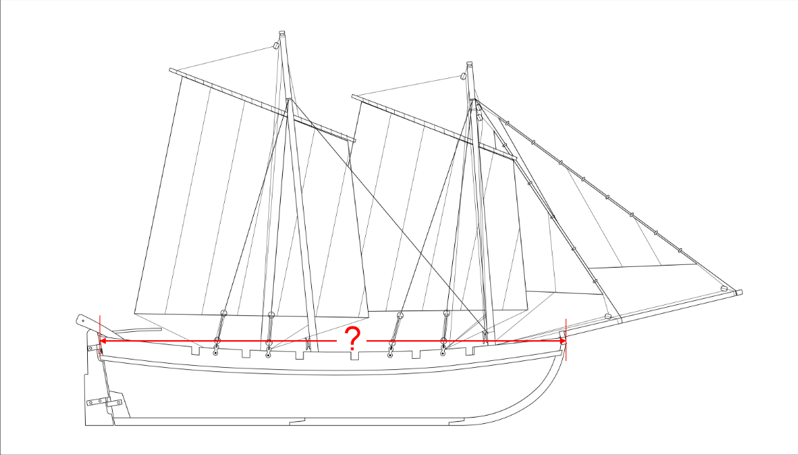
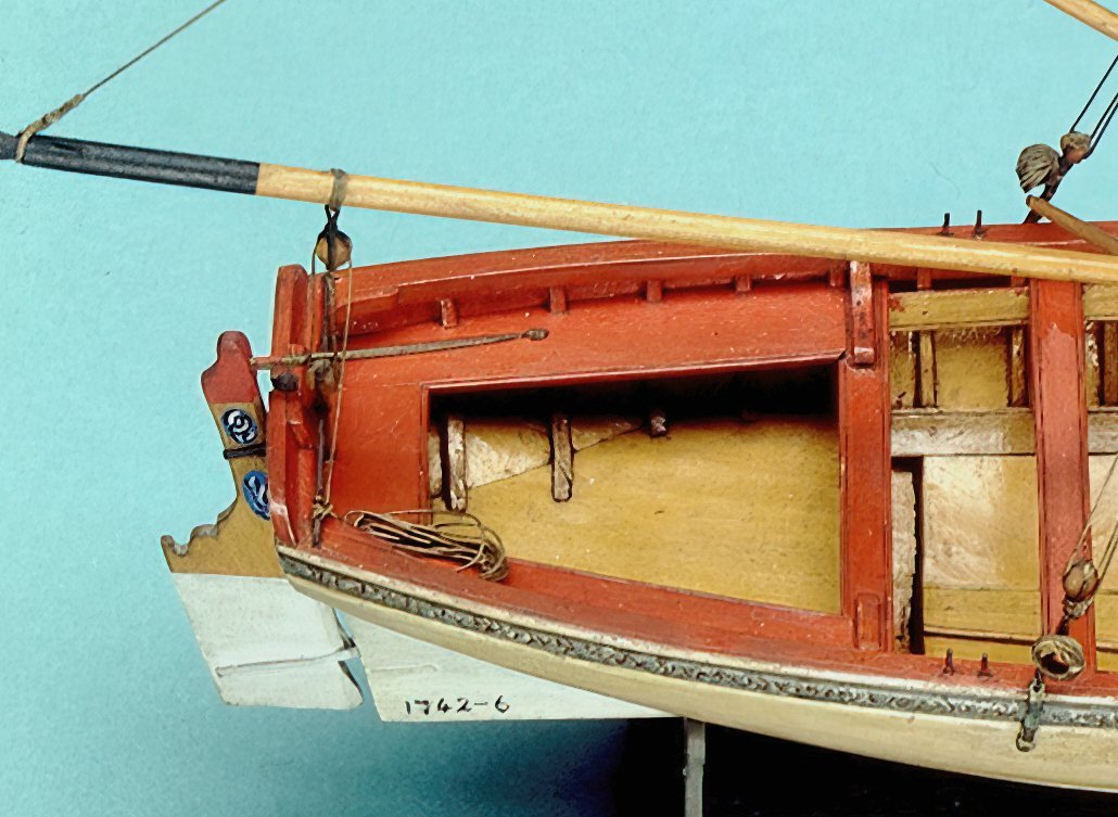
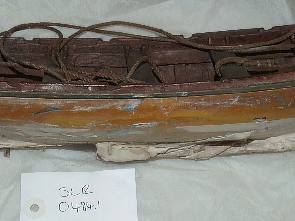
I have been trying to work out what size boat this model depicts, could you do one measurement for me? Thanks,