


stuglo
-
Posts
701 -
Joined
-
Last visited
Content Type
Profiles
Forums
Gallery
Events
Posts posted by stuglo
-
-
23 hours ago, ted99 said:
Usually depends on type of plastic. Almost any of the liquid types work with the most common styrene. ABS needs a different solvent. The key is to use one of the bottles of thin clear liquid, not anything that is thickened and in a tube. Hold the pieces to be fastened together after trial fitting and use a VERY small brush (not the one that comes in the bottle) to apply a very small amount to the joining line and let capillary action pull the "glue" into the crack. It's really not glue, it's a solvent that softens the plastic part at the joining line and the two parts "weld" together. Usually best if you are able to keep pressure on the join line until the styrene at the join line re-solidifies when the solvent evaporates.
CA glue can be used for plastic to wood or metal. In looking ahead at the instructions for our kit, there are some PE brass facing sheets to be glued to both plastic and ply. The instructions say to use CA for these joins, but they have a lot of surface area and I'm going to approach this carefully. One of the things I'm going to experiment with is using a high-quality contact cement (like Barge) that has been thinned and apply it with a flat brush to the back of the PE brass sheet and to the plastic or ply surface. I'll try this on some scrap first and report on it in my build log. I also see that there are some small PE detail parts that are to be attached to PE brass bulkhead sheets. Instructions seem to use CA glue, but I'm going to investigate soldering these parts.
Never heard of ABS before. If you mention this I assume you know this is the stuff used in the kit. ? similar to plexiglass, which I "glue" with chloroform?
-
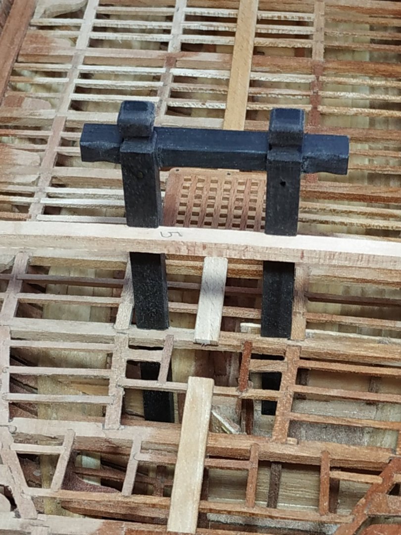
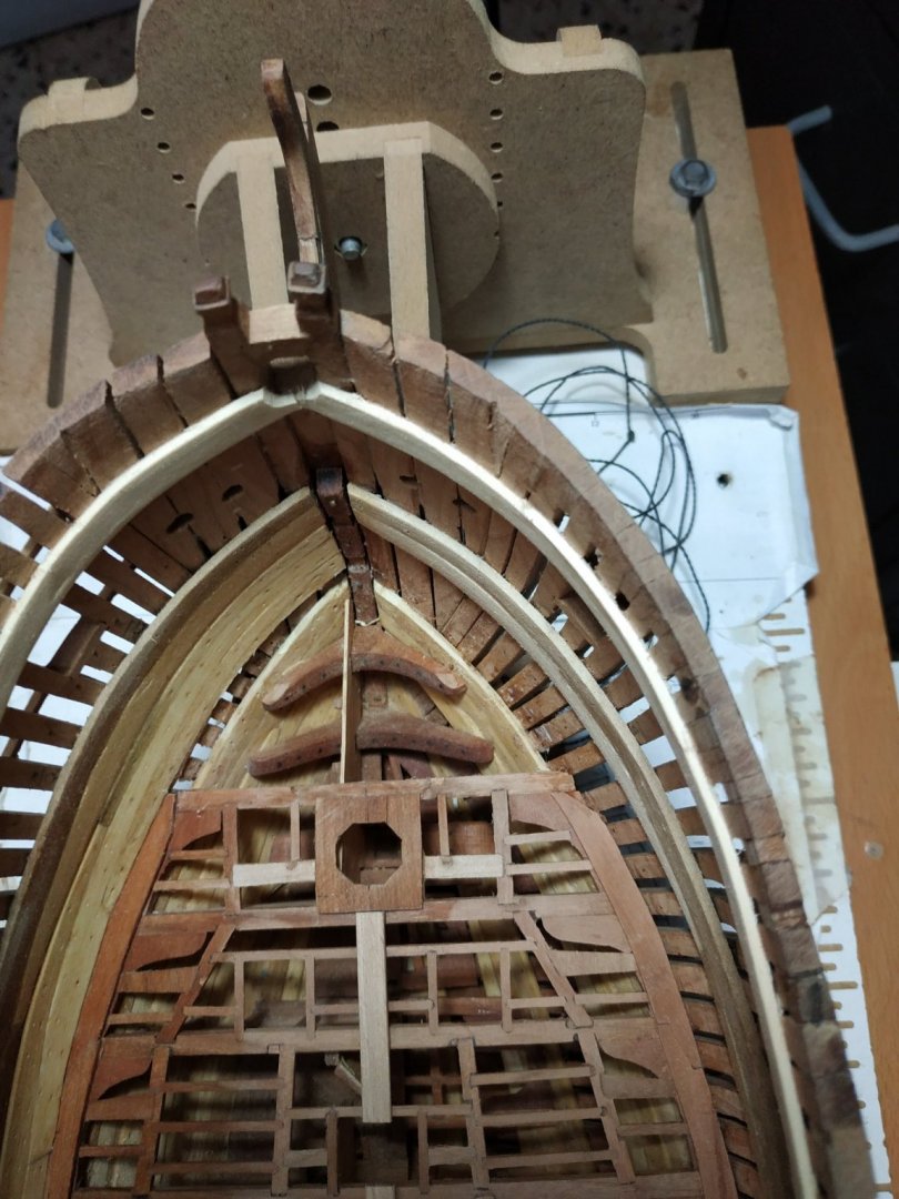
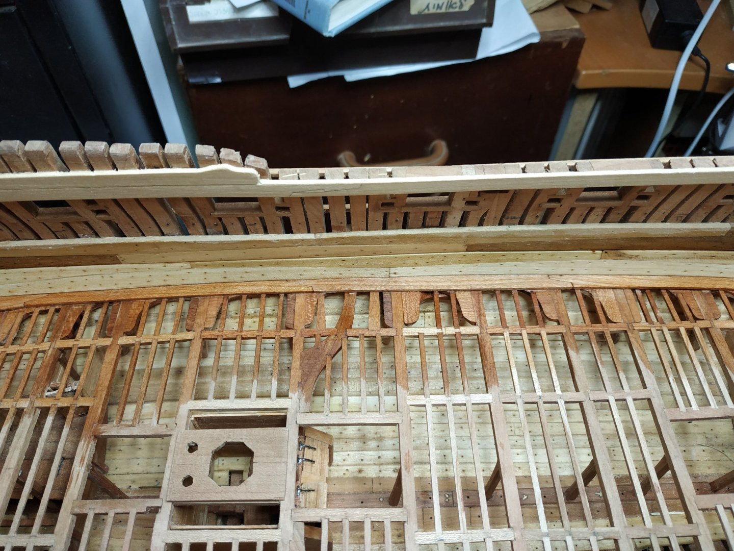
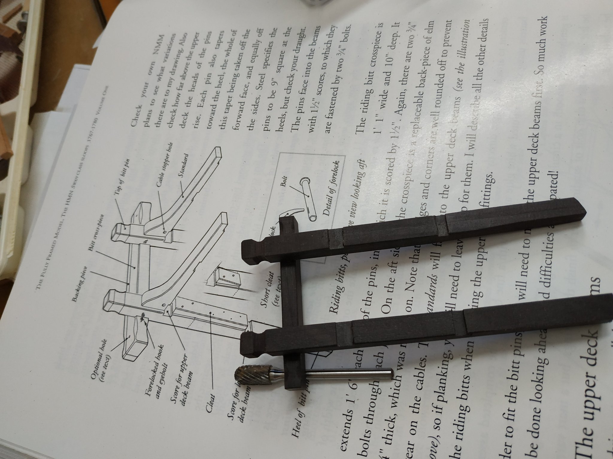
Riding Bitts
The Pins of these have previously been made-they support the aft aspect of #5 lower deck beam.
They are repositioned, and checked to see if they are perpendicular. Slightly out, the scoring depth increased from 0.8mm to 1mm, did the job.
The #5 upper deck beam is positioned and its height is checked using the profile plan. In this case, resting,without letting down,gave the desired result.
This is marked against the Pins, and the scoring of 0.8mm is made using the milling machine.
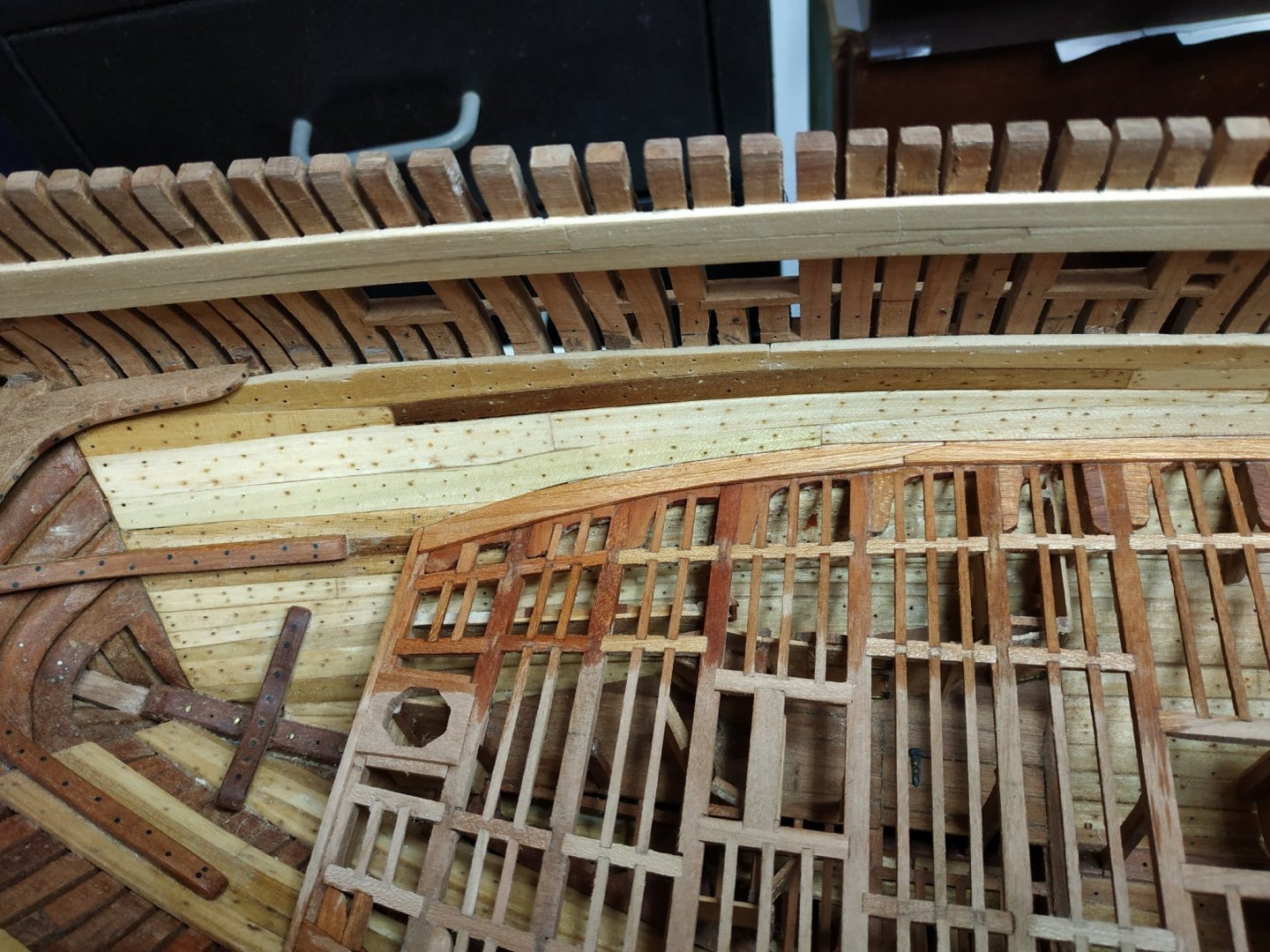
The cross piece is now to be made.-6.89mm x 5.3mm of length 56.85mm.
The head is grooved with the shaped milling piece and the edges chamfered. (except aft - another piece will be added later).
Height (position) on the Pins is marked and again scored to 0.8mm.
The cross piece is fixed to the Pins, allowing 23.85 space between them,and the edges of the fore aspect chamfered - the more so the edges of the extensions outside of the Pins.
(I’ll leave it off the model until most of the deck is completed)

- mtaylor and GrandpaPhil
-
 2
2
-
Lower Deck Planking-cont.
In fact, before continuing, suggested making the Riding Bitts.
The PINS for this were made,so to fit location aft of #5 beam, where it is scored so as to support said beam.
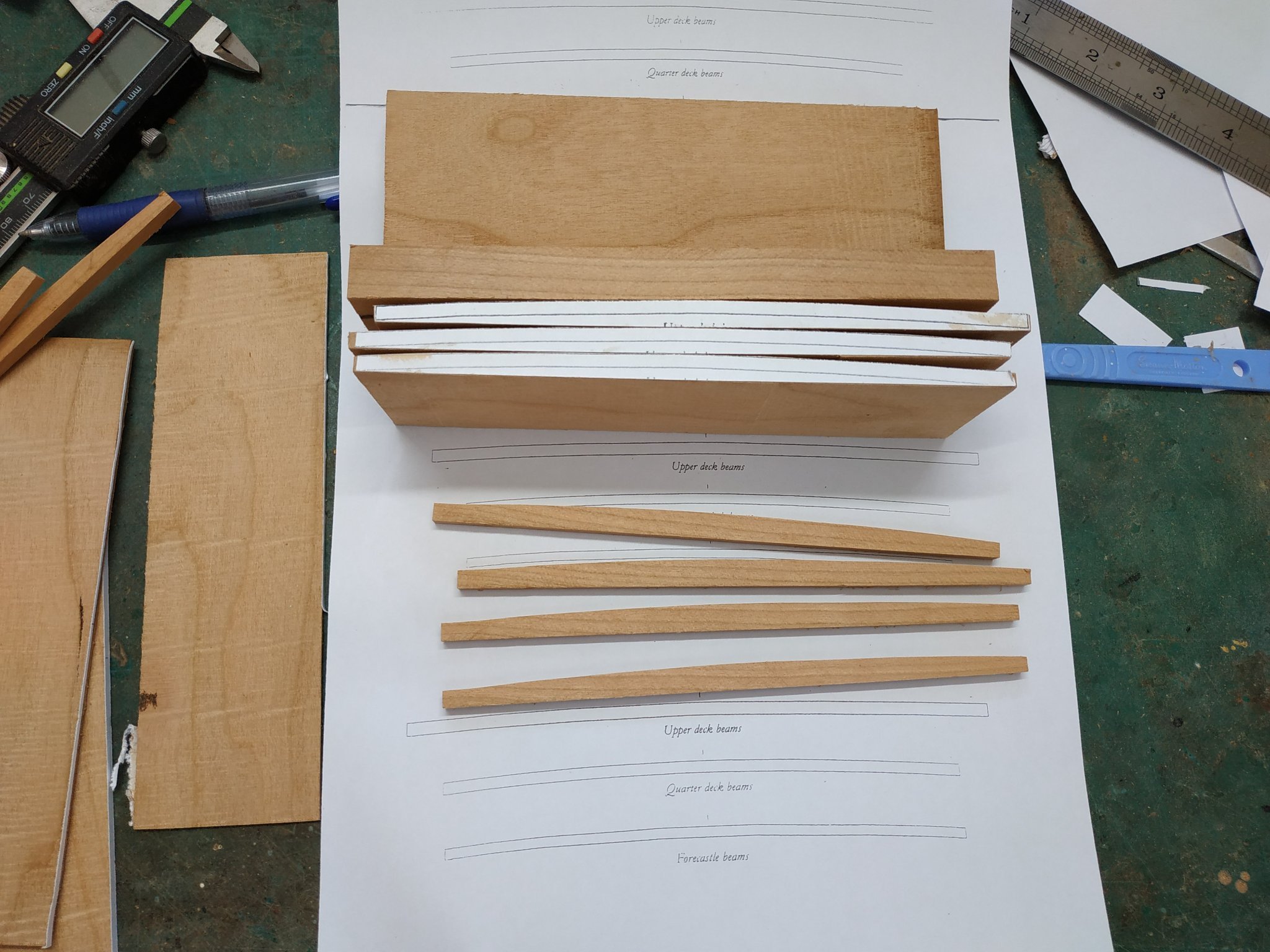
These Pins must be scored to fit the UPPER deck beams-Which therefore have to be made first and appropriately positioned.
My bible, T(testament)FFM, refers me back to section 5.10 “as you did the lower deck”.
Luckily, I checked with ch. 8.4 (vol. 2 -Deuteronomy) where I found that the upper beam deck size is given as 4.77mm X 3.71mm and some words as to whether to let down onto the clamps or not. (Changes in instructions are also known when repeated in the other Bible).
22 beams are required.
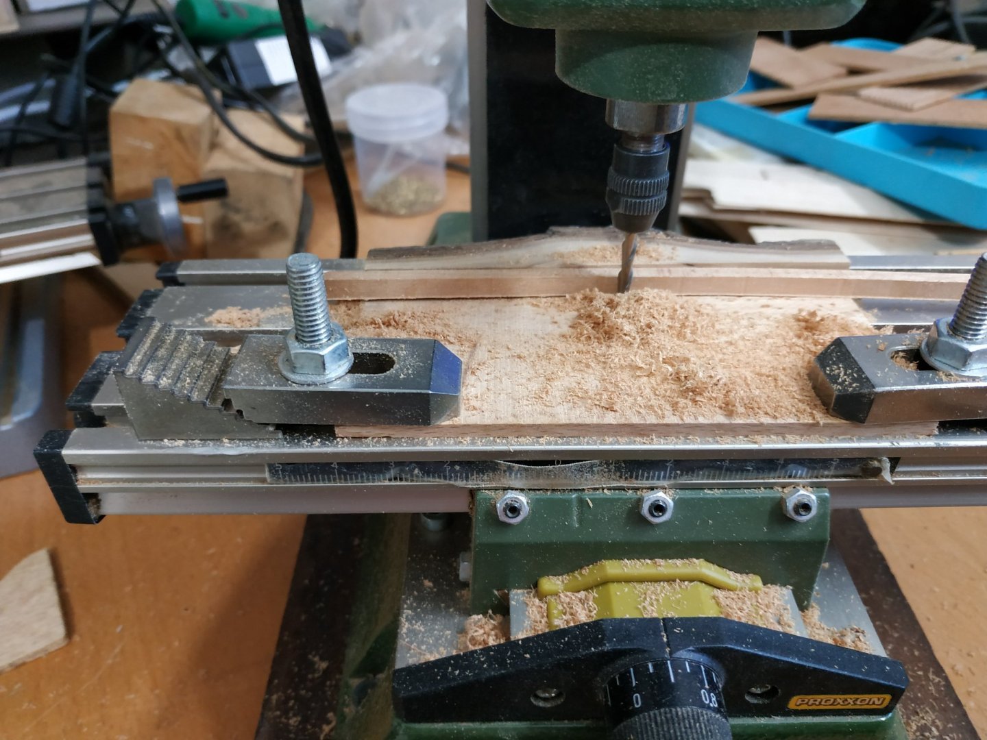
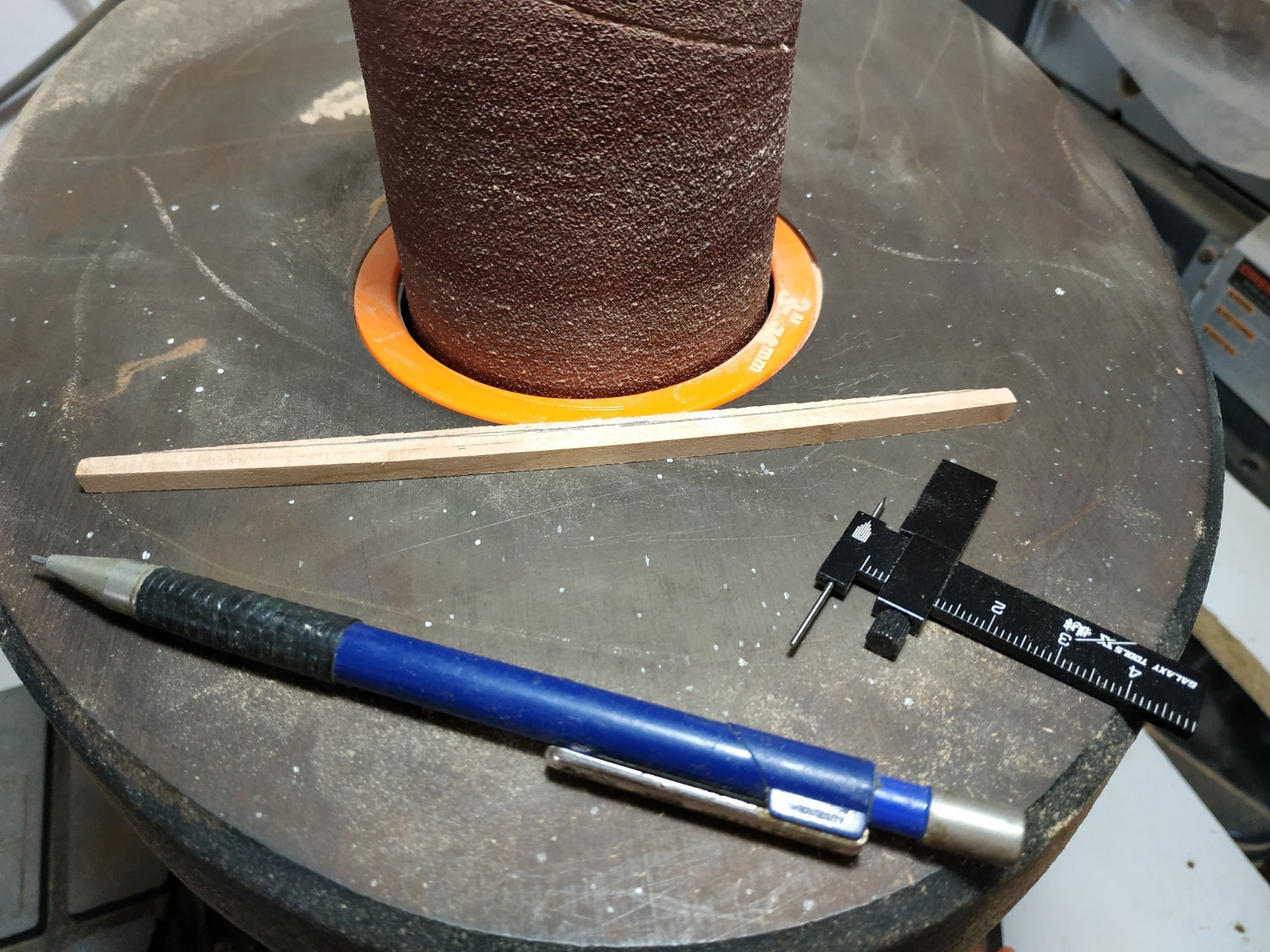
Having tried various ways previously, I used the following method.
4 blocks, 16.5cm length, 5cmdeep and 1.0cm wide. (Thinner difficult to keep at 90deg)
Cut out pattern both sides of width.
Convex side, formed with spindle sander-flipping over frequently to ensure equal 90deg (same effect)
4.77mm slices with the table saw
Inscribe parallel line to form the concave surface( a little wider than the 3.71mm)
Finish more accurately with several passes between the milling drill bit and a fixed resistance.
The gap narrows progressively until the required thickness is obtained.
The beam passing by the bit, needs stabilizing as it passes the bit (I use a finger)
This way I only ruined 20% !!!!


- mtaylor, ccoyle and GrandpaPhil
-
3
-
1 hour ago, mtaylor said:
Is this a saw or thicknesser? If it's a thickness sander, your grit may be too rough. If it's a saw, check that the blade's teeth aren't offset and also go for a higher tooth count. Here's a good reference for table saws and blades and even though it's for the Byrnes it's very helpful for other saws. https://modelshipworld.com/topic/23843-byrnes-saw-reference-also-good-for-other-desktop-hobby-saws/
a proxxon- blades on a rotating wheal- an electric plane.
-
4 minutes ago, noel_colledge said:
On post 432 you mention
"Battens: My thicknesser can’t make 0.4mm blanks -only 1.3 minimum.
Never mind."
if you have a dead flat piece of wood or metal the width of you thicknesser, you can double sided tape your wood to this sled and reduce the thickness of your timber to less than 1.3 mm by passing it through on the sled.
tried but the proxxon (mine at least) is unforgiving and tends to chew up v. thin or shorter pieces. Possible the blade settings, but have,'t yet the courage to play with them. For small pieces, I use a milling machine.
-
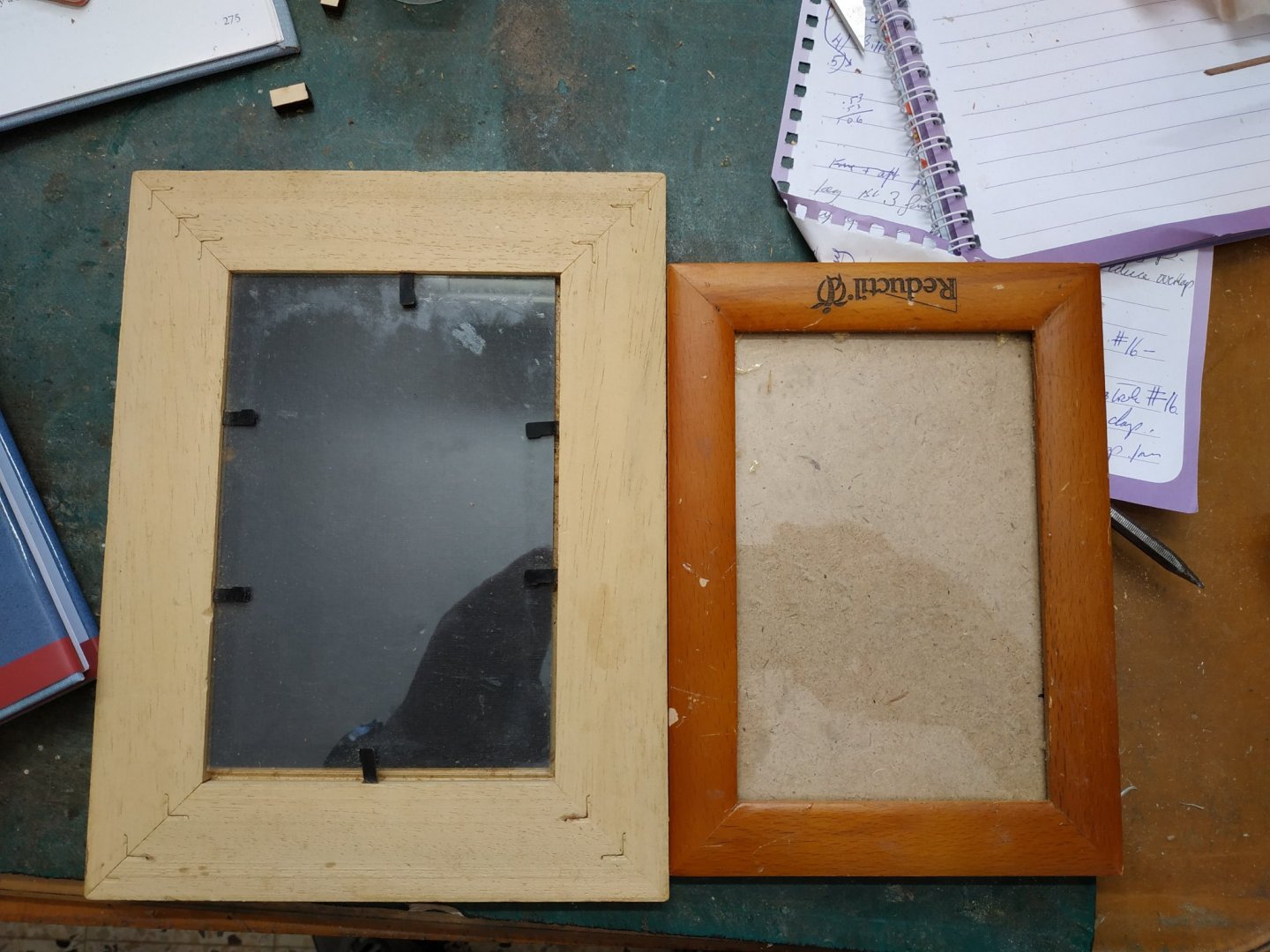
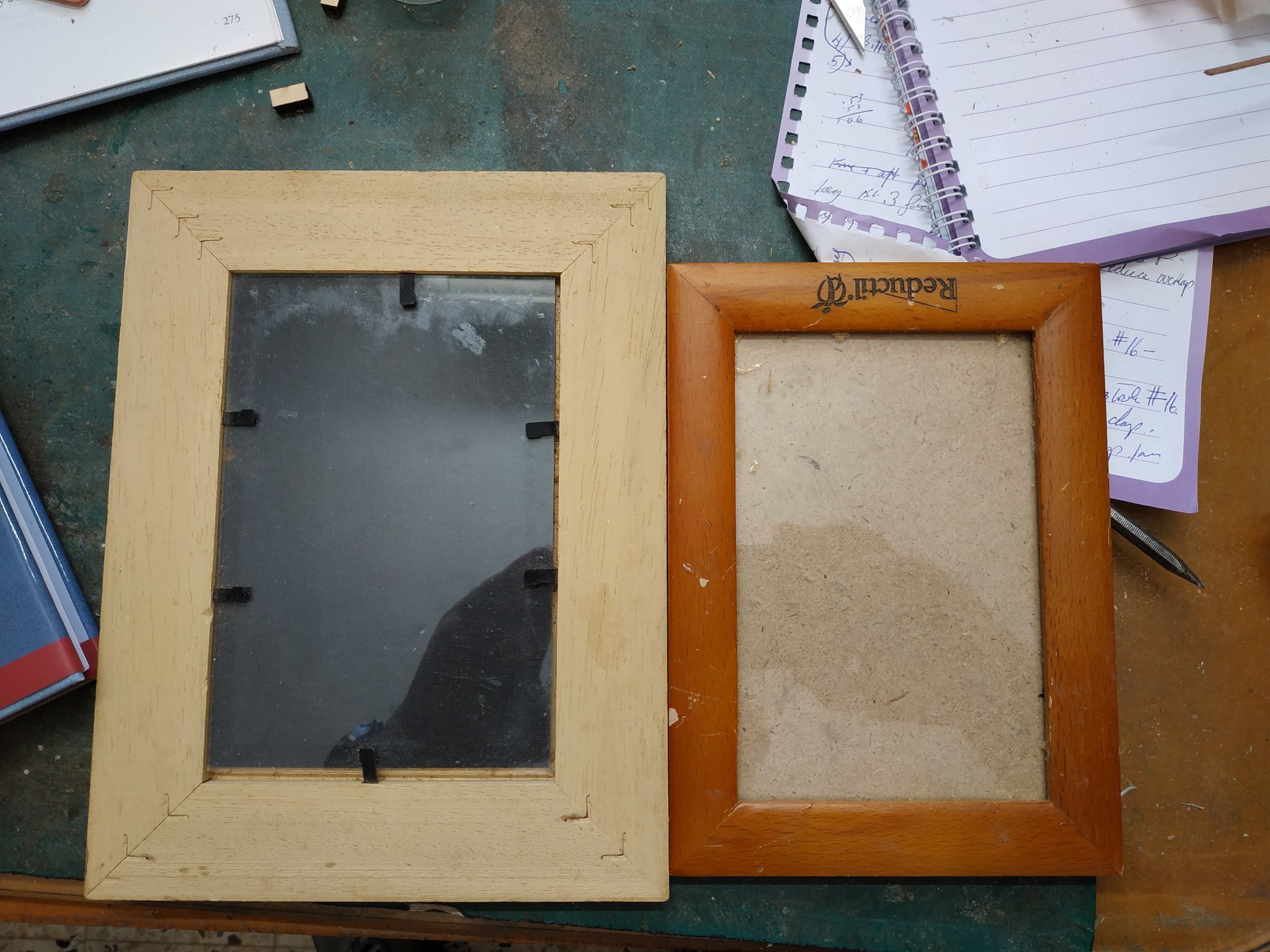
Kevin, Another Idea that I meant to pass on when I saw the gluing of right-angled parts, for which you use clamps and jig on glass.
Try an old photo frame. The angle and glass always there. Also I can place pattern under the glass and stick bits into position without them sticking to the plan.
- mtaylor and GrandpaPhil
-
2
-
11 hours ago, Kevin Kenny said:
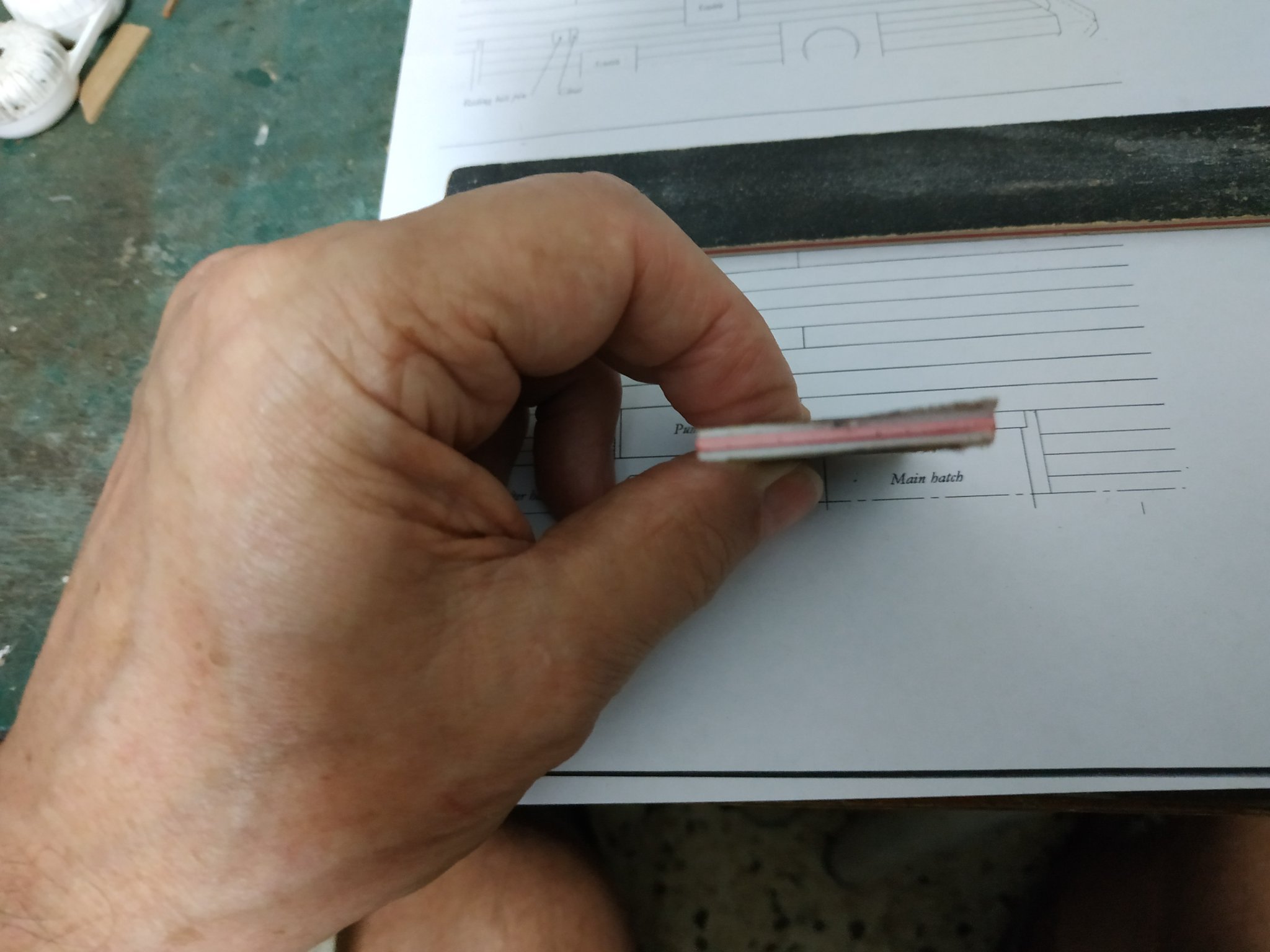
Just curious if you catered for the slight increase on the outer edge of the waterway which touches the frames. I am struggling to do this on the waterway for the upper deck where the plank starts at 4” then reduces after the spirketting to three inches
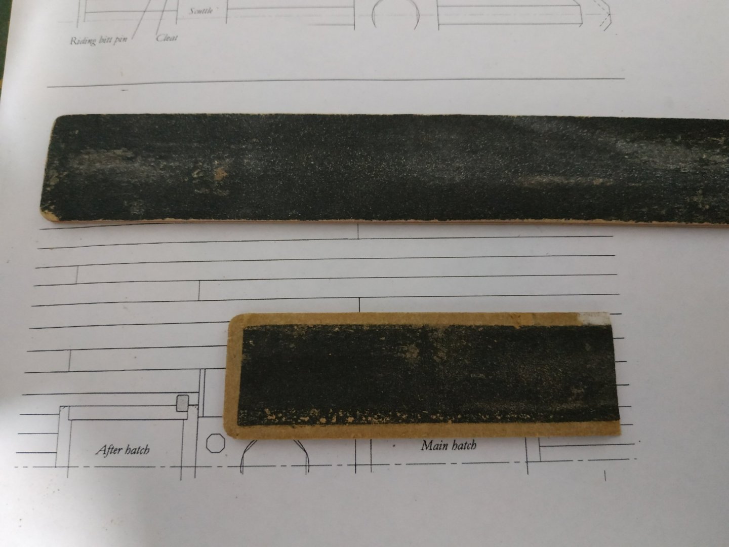
try this out.
I took an already well-used emory board (less abrasive) of softer sandwich type. Cut a 3mm rim of the sand paper layer away. The edges are soft and non-damaging to the wood you wish to be un-effected. (the already-rounded corner is a useful bonus)

- mtaylor and GrandpaPhil
-
2
-
-
2 hours ago, Kevin Kenny said:
Just curious if you catered for the slight increase on the outer edge of the waterway which touches the frames. I am struggling to do this on the waterway for the upper deck where the plank starts at 4” then reduces after the spirketting to three inches
Intend to do so after I fit other planks. These will need sanding and my initial intension is to sand the outer waterway to match their level
-
Return to Deck Hook and Eking Piece.
When placing the foremost part of the central plank I realised I had made a fundamental error. In forgetting the TFFM instruction, I made the Eking piece stand proud of the beam,by dropping the beam, so that the waterway plank ended flush with this. So the front end of the deck needed unsticking. It and #1and #2 beams,the foremost waterway planks remade, and a new central piece joining the to the stemson, so they overlay the Deck Hook.
( As Miss Piggy would say “ attacked by DUMMO rays”)
- mtaylor, ccoyle, Ryland Craze and 4 others
-
7
-
-
-
-
Hi Ted 99
The fittings were in a small box with the rigging cords and copper nails etc.. The Large view is mentioned above the 6 plans.
UPS express saver- but the company here takes advantage as price only quoted after arrives at local customs. (Called customs, as it is the custom to screw us, the private buyers.)
-
"I am missing one package of small plastic detail parts-- "vents"."
I'd better check my plastic bits as well.
"Total shipped to the USA was 456.83 GBP"
lucky you -my shipping was 115GBP ( the distance is 20% LESS) + 140 GBP tax + 80GBP local handling charge. But I still think worth it .
My enthusiasm somewhat waned when I saw missing and damaged pieces, but is reviving when I see my kids and grandkids fighting over who will get the finished model.
-
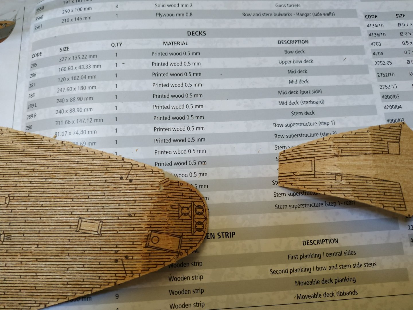
FOR WHEN I FINISH THE SWAN OR NEED A DIVERTION
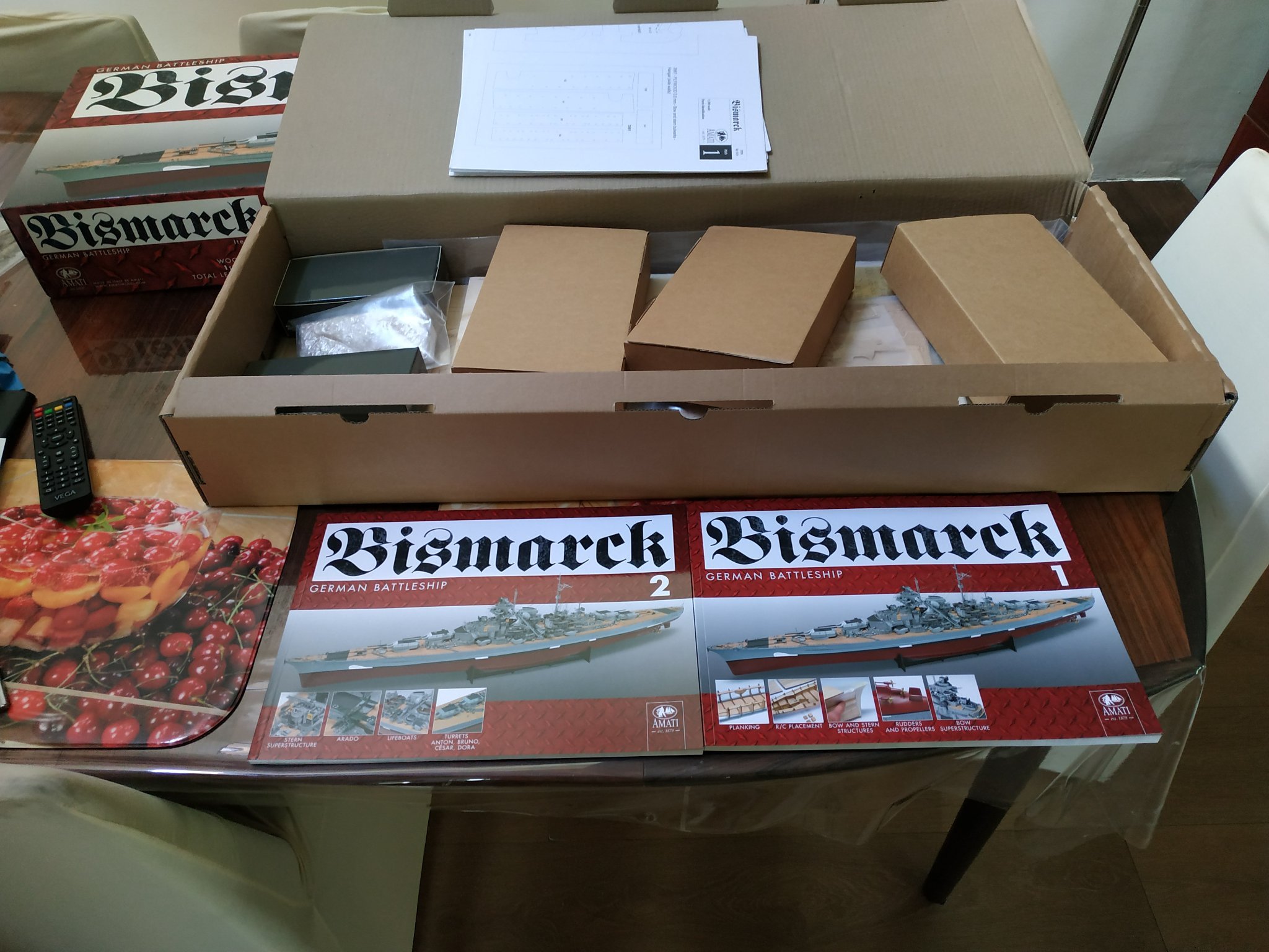
Just Delivered (not by a Stork- a WW2 German plane)
Almost healthy girl (ships are "she") weighing in at 9kilo and expected to grow to 127cms
Thanks to advice to check and notify, found some metal bits missing, as was the printed large view.
Also. the contents were loosely packed and the ends of the printed bow pieces damaged-replacements requested.
Amati is a long established company and they should employ an English-speaking proof reader.
The outside of the box states that the Bismarck was the PROUD (sic) of the navy..... and the MITH (sic) began.
Not in the mood to check the TWO books of illustrated instructions

-
Just Delivered (not by a Stork- a WW2 German plane)
Almost healthy girl (ships are "she") weighing in at 9kilo and expected to grow to 127cms
Thanks to above advice to check and notify, found some metal bits missing, as was the printed large view.
Also. the contents were loosely packed and the ends of the printed bow pieces damaged-replacements requested.
Amati is a long established company and they should employ an English-speaking proof reader.
The outside of the box states that the Bismarck was the PROUD (sic) of the navy..... and the MITH (sic) began.
Not in the mood to check the TWO books of illustrated instructions


-
-
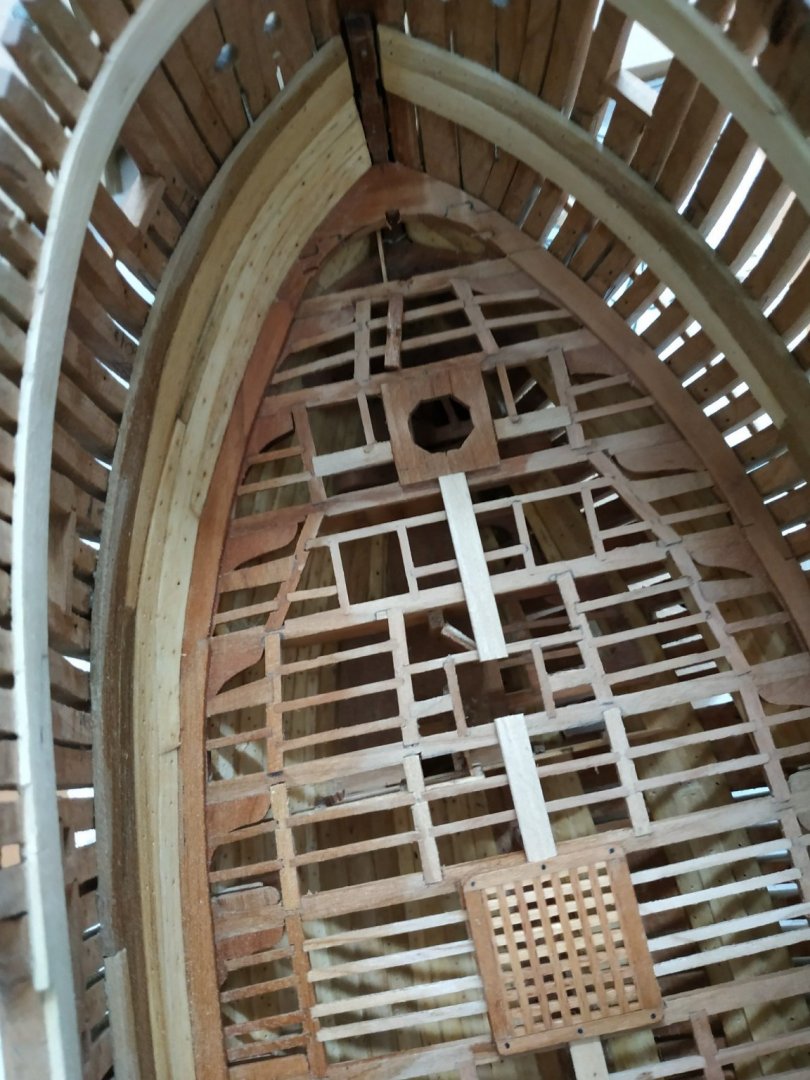
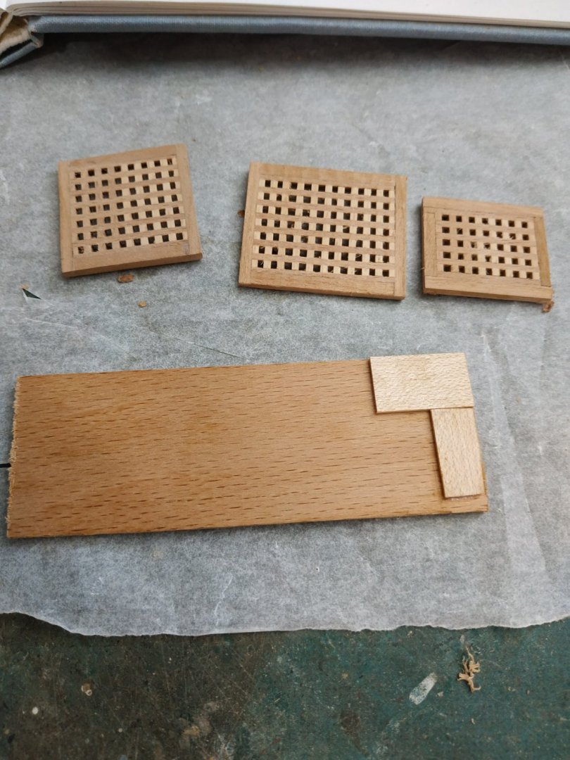
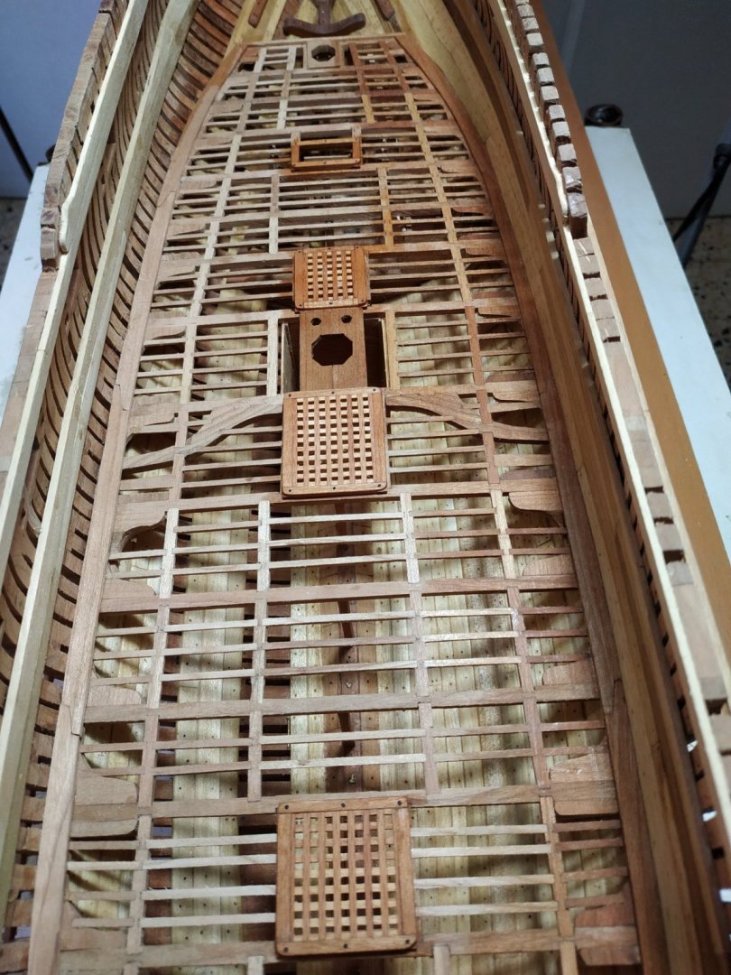
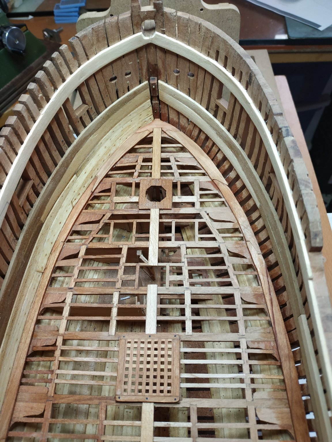
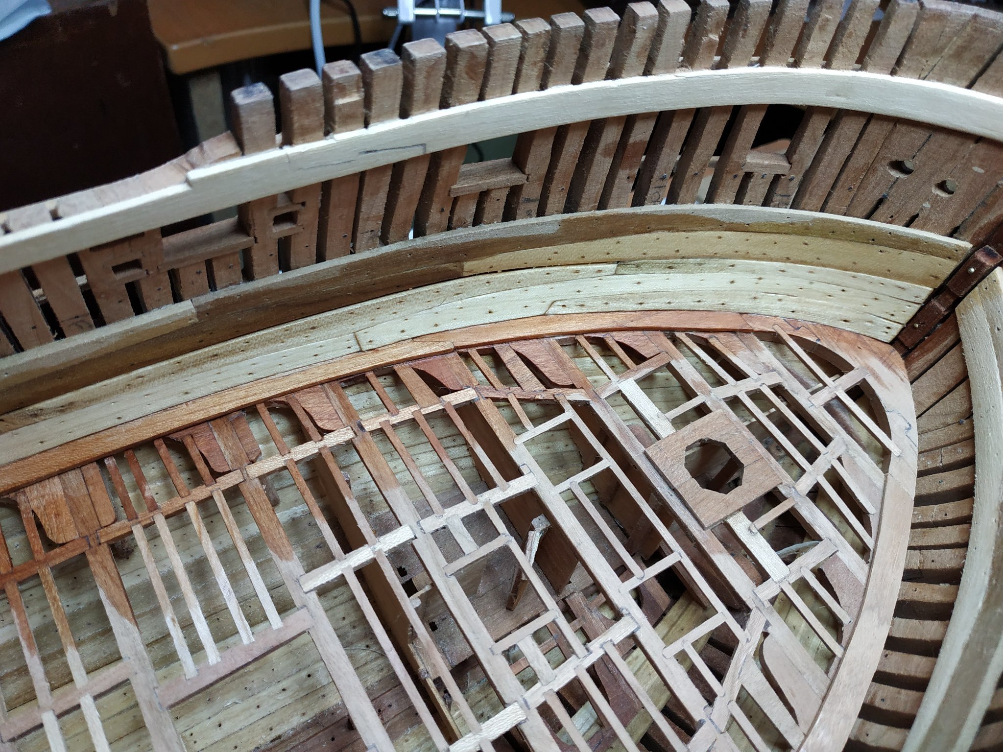
Hatch Coamings.
Framework around the gratings and ladder opening.
The aft/forward (also called coamings) are 3.18mm x 2.65mm (deep)
Athwartship, head-ledges, are 2.65mm.
The corner joints are a fancy half lap, said to be sloped or angled-this extra feature beyond me. In order to see the joint-line, the upper piece is simply made thinner.(1.25/1.40).
The upper part of the joint, seen above the planks, is rounded off. A small jig with a right-angle of a plank to be used, served to “blank off” the lower part that will remain square after sanding this rounding(also called radialising).
The grating should be thinned to reach the appropriate thickness. I used the milling machine as my attempts with a sanding board resulted in unwanted curving.
Black wood treenails represent bolts placed at joints and the center of the frame.
(Although I used different woods for the frame and gratings, when oiled, this is difficult to see. Different choice for other decks.)
- druxey, mtaylor and GrandpaPhil
-
3
-
-
-
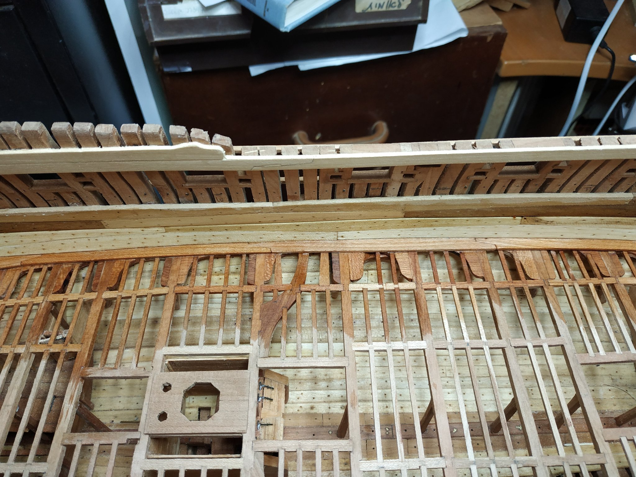
Lower Deck (cont.)
Before planking, some structures need to be made.
The first are the Gratings.
These have always seemed too difficult and in previous scratch builds, have used left-over pieces from various kits and assembled them.
I’ve read dozens of explanations which seemed too difficult to build or even understand.
Even the TFFM didn't enlighten me. Then I checked out a later video of Kevin Kenny (#79).
Genius (someone who simplifies the difficult and/or originates a new method)
THANK YOU, SIR.
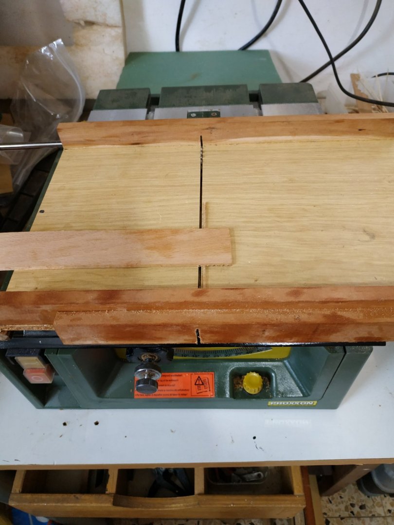
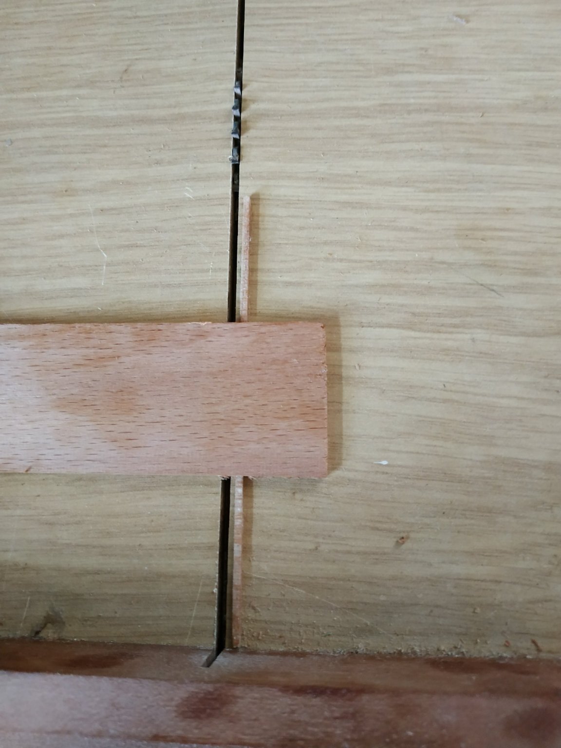
First, make a sliding table (in my case , a ProxxonFET).
The gratings consist of : ledges (athwartship)- the notched bits-1.33mmX1.6mm (deep)
And for/aft Battens, 1.46mmX0.4mm thick.
My saw blade is 1.6mm (very convenient).
A stop/fence made from a strip 1.6mmX1.6mm, and glued at a distance that a cut strip will be 1.6mm wide, (For now relied directly on sliding table and not an additional jig.)
A 3mm thick blank is squared off, and with the grain at RIGHT angles to the blade,which is lowered to allow a 1.6mm groove to be made.
Held firmly against the fence, the first cut is made.
The blank is then moved so this groove SITS on the fence, and a second groove cut. This in turn sits on the groove and another groove cut etc until all the blank is furrowed.
WATCH OUT FOR THE SAW BLADE.
(I placed some downward pressure to help form uniform grooves)
As I said, sheer Genius.
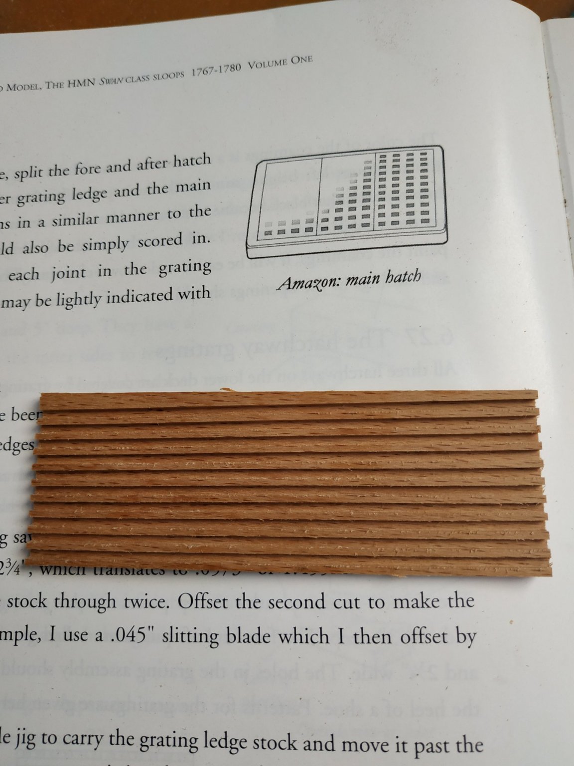
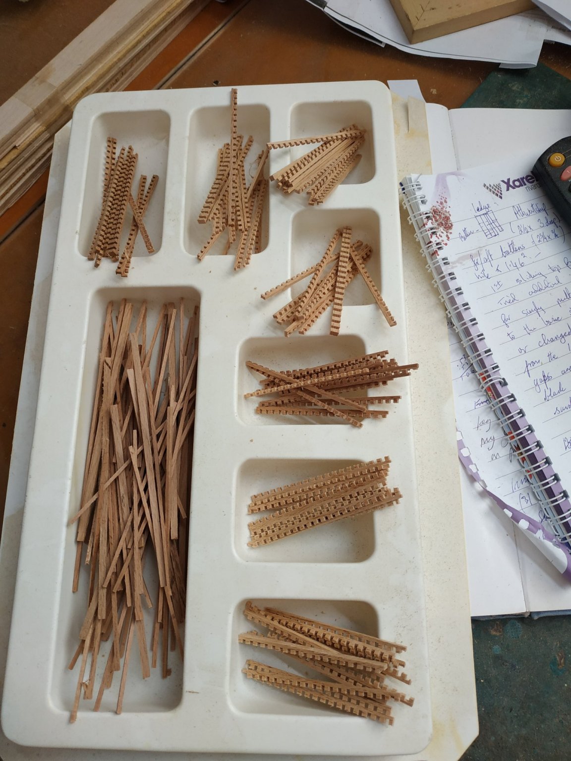
While set up, made enough for later use with the upper deck.(Foredeck more delicate)
Put the sliding table aside .
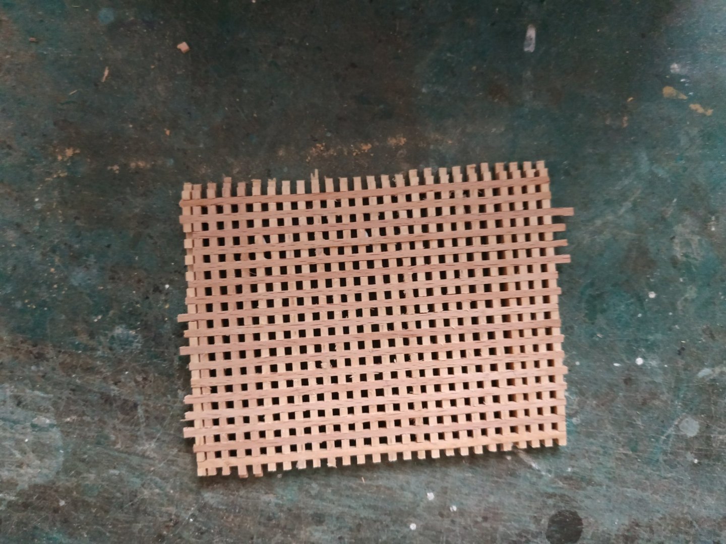
These grooved blanks are turned 90deg and 1.6 mm slices cut with the grain
I changed the saw blade from the standard 37 teeth ( it damaged a few trial passes) to a 200 tooth blade-not really its purpose, but it was magic) and cut the 1.6mm wide strips ALONG the grain.
Battens: My thicknesser can’t make 0.4mm blanks -only 1.3 minimum.
Never mind.
Cut strips ( ALONG grain) similarly 1.6mm wide
The ledges and battens are interlocked and fixed with diluted glue.
The holes seem pretty uniform and close enough to the appropriate size.
The excessive thickness will be sanded off after each piece is cut to size.
Thanks again Kevin.


- GrandpaPhil, mtaylor, druxey and 2 others
-
5
-
On 12/29/2019 at 9:40 PM, stuglo said:
STOP !STOP! STOP ! you keep showing kits that I MUST have. This looks incredibly good and (sorry) wood is far better to work with than plastic. My wish list is growing in inverse proportion to my modelling life expectancy but this will near the top of that list. The variety of content will be a worthwhile challenge and the price mentioned seems reasonable compared to other kits (eg my Amerigo Vespucci). Please keep us updated.
Ssshhh- a certain company in SW England is now taking orders. My Bosun is in for a surprise .
-
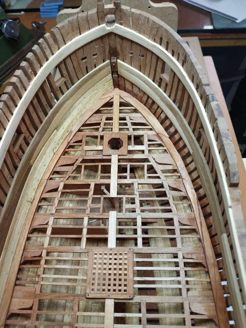
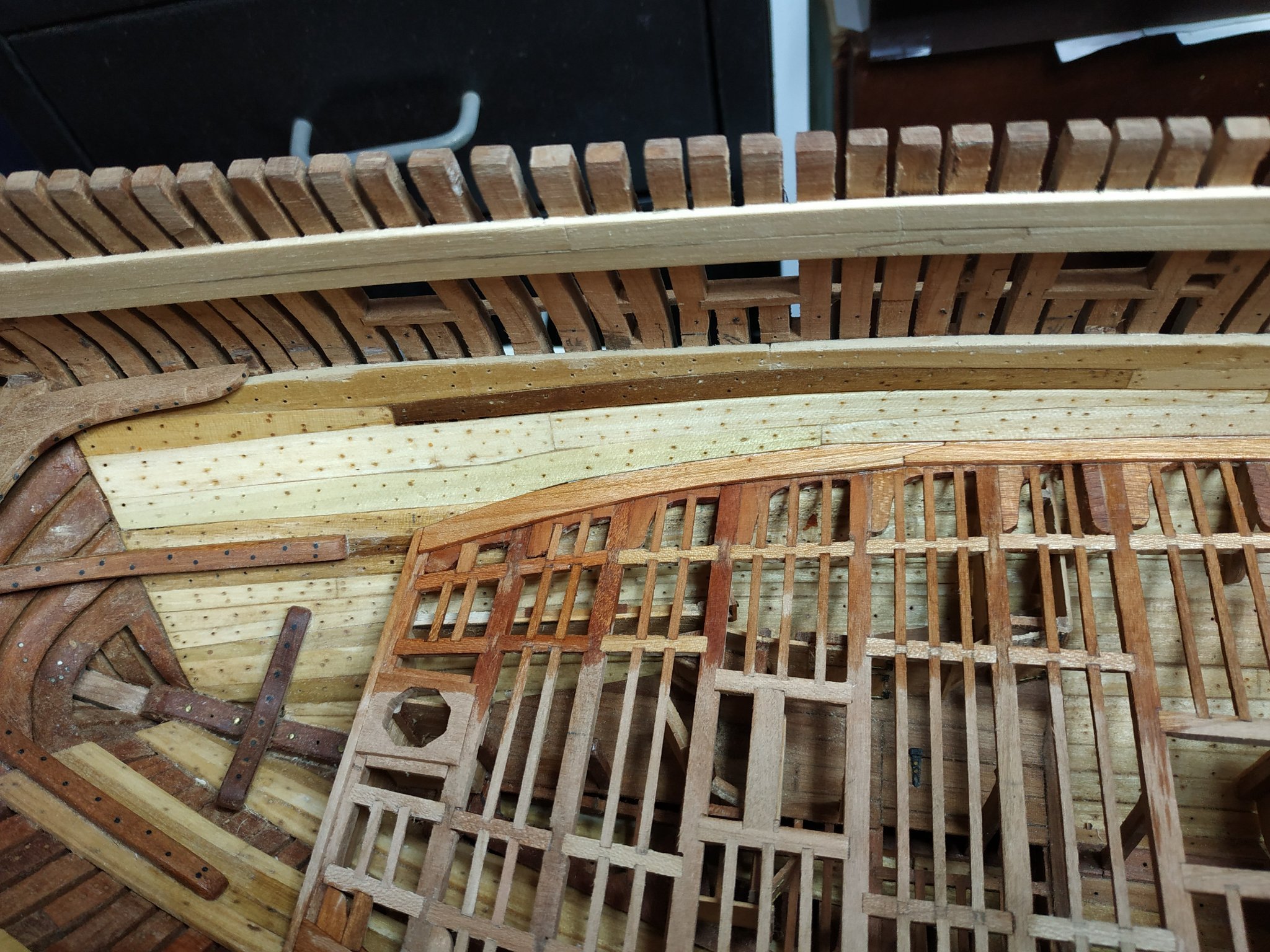
Inner Hull Planking (ceiling) cont.
#16 and #17 strakes of 1.6mm thick
A stealer is added below the foremost part of #16.
I found it easier to chamfer the lower edge of the #16 strakes, rather than the inner waterway.
There is an (Air) gap of 1 mm above the #17 sections except the foremost and aft, which are wider by the same amount. The lower edge of this gap is chamfered
I also fit the aft #17 first, as the #16 aft shape is more complex/
(I find it difficult to transfer a card pattern to wood, and in this section I have made approximate paper patterns and then fashion the wood directly with sanding sticks and band sander.)

- VTHokiEE, tlevine, GrandpaPhil and 5 others
-
8


Sandpaper
in Modeling tools and Workshop Equipment
Posted
Single edge razor blade or 22/24 scalpel blades