


stuglo
-
Posts
702 -
Joined
-
Last visited
Content Type
Profiles
Forums
Gallery
Events
Posts posted by stuglo
-
-
Need help/advice
Now making the the square frames as suggested -reducing size pats/futtocks-10",9.5" and 9".
I tapered the transition points and ended with timber tops too thin or wave profile.
Should the transition points -chock or scarf- be left as step?
What have I forgotten or not understood?
-
Knee of the Head
(my dyslexic son referred to the ”elbow in his leg“ instead of knee)
The good news is that we finished chapter 2 (TFFM)!!!
This is a set of seemingly simple pieces that make up the foremost part of the ship
The gripe was easy- I had already made it when I made the stem -not yet fitted but fortunately found in a “safe”box of bits.The blank is 5.3mm
Need to remove from the building slip to fit these parts, which is worrying as the keel is very vulnerable. I supported it with a large piece of sponge.
This, and other parts abutting the stem, have “felt”-black paper- filling the joint.
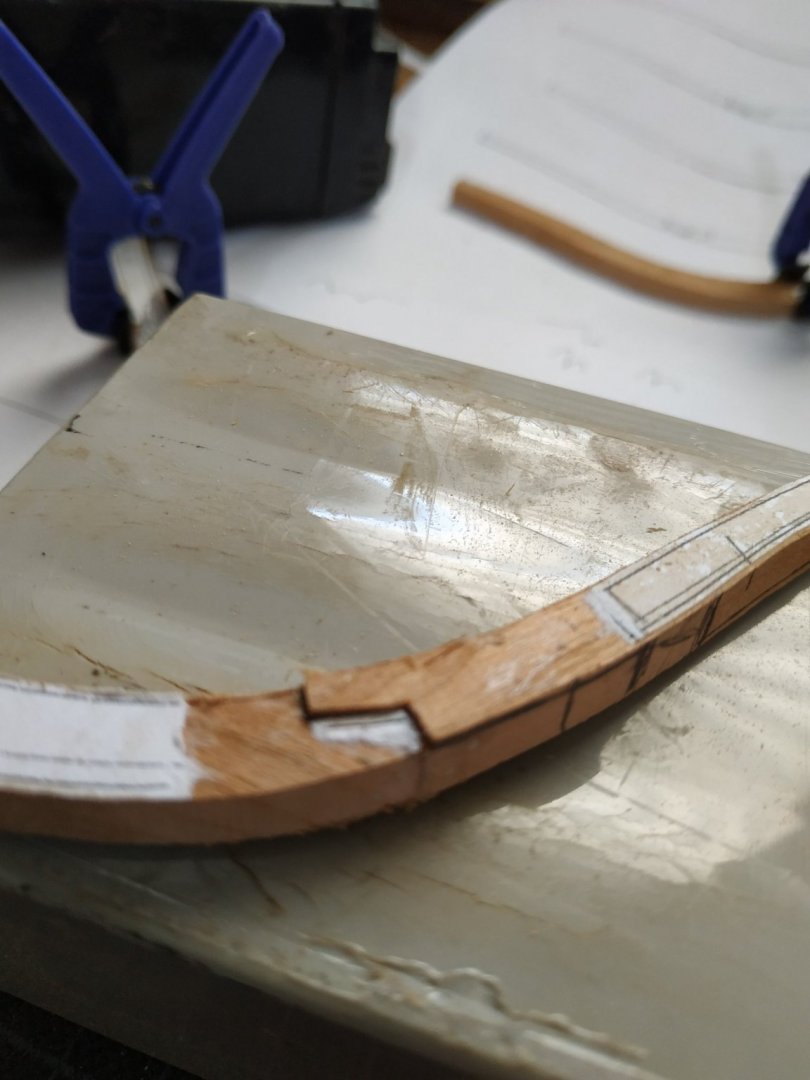
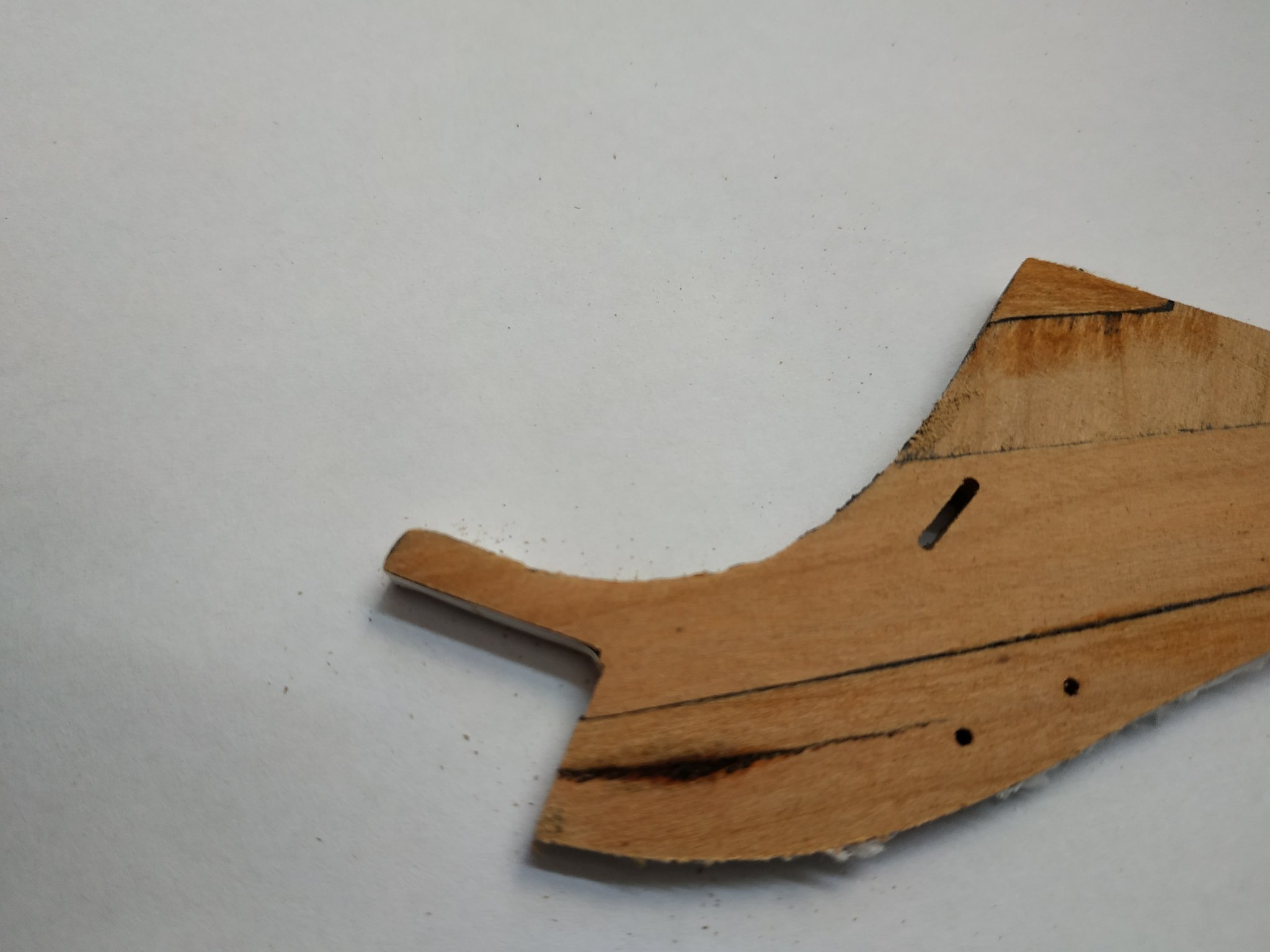
The next pieces, chock, cutwater,lacing piece and bobstay piece are cut out from 5.3mm blanks.Here I cut on the pattern line, and the pieces fit well.
Note the TFFM comment on the line of upper curve of lacing piece-a faint line under upper cheek,where it joins the extension piece.
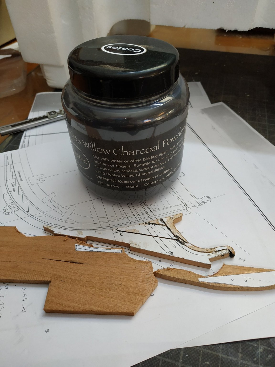
The pieces at various angles to the grain and joined by “black” glue (PVA+charcoal) - the contrast looks better this way.
Dry fit to the curve of the stem, with adjustments as necessary- a few light touches with the spindle sander was effective.
Bobstay holes and gammoning slot as shown, with milling piece #56
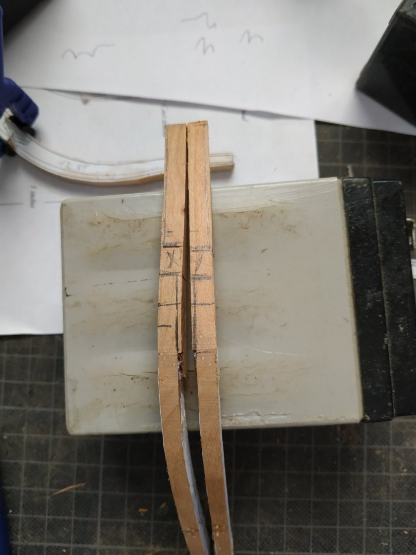
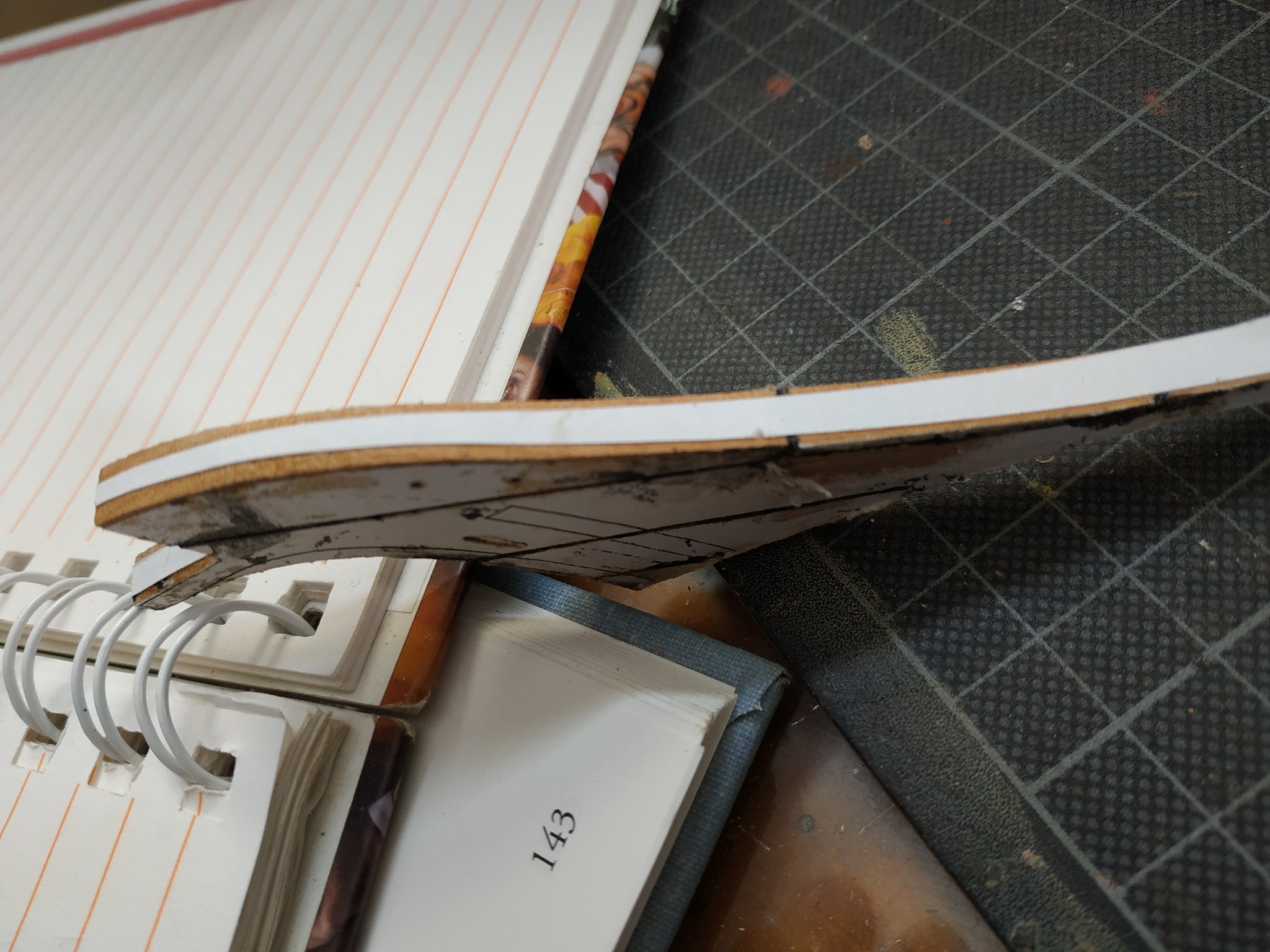
The combined piece needs tapering -from 5.3 to 2.12 mm at top of bobstay piece- the top of lacing pieces only to 3.18mm.That is from below, above and aft, forward .
As before, I did this by cutting a pattern of this taper and sticking this to the fore curve.
Tapering by alternate sanding on stati sanding board.
A small imperfection in the wood was noted on the bobstay piece but I expected that this would be removed with the taper. Instead it grew like some cancerous iceberg.No camouflaging this.
(Of course the piece with the extra work-holes and slot)
Remove and, of course, the cutwater was damaged, and this also had to be remade.
Another lesson I must remember- don’t waste time on suspect material.
When satisfied with taper, glue felt for joint to stem.
More mistakes- didn’t allow for thickness of felt and didn’t notice thoat snug fit caused the the gripe to lift away.
Reset and the felt removed , some sanding to allow for felt in joint.And reattached.
Glue reinforced with wooden trunnels from aft aspect of stem. These are limited because the thin drill bits are short.
Augmented adhesion with rubber band and S@@$%T- all slipped off, taking gripe with it.
Again clean all up (paper and glue is messy) and try again- this time with copper wire trunnels from front and back- and finger pressure. Ensure alignment with string midline from top of building slip supports for and aft.
? How to improve bond when using the intervening paper- wood is not being glued directly to wood.
While setting, made the last 2 upper pieces- standard and extension pieces.
These are thinner , 3.71 tapering to 3.18 (matching top of lacingpiece). Added the hole (larger, use #52) and the aft gammoning slit.
Fitted them separately, but perhaps would have been easier to glue together before final shaping.
Used coloured glue for joint-not sure if this was ok join to stem, but sick of using the black paper.
Difficult to clean up-was frightened of breaking it off.


-
Received mine after about 8 weeks- travelled half the world by DHL. International post at "cheaper" end is bad. The book (TFFM vol 4) worth the wait. The source is not to blame
- druxey, Keithbrad80, thibaultron and 1 other
-
 4
4
-
On 1/1/2021 at 4:06 PM, druxey said:
"The first time one frames a model is the hardest, as there is no substitute for experience."
I fully agree. Each time I look I see mistakes and inadequate finishing. I keep thinking whether its too late to start again or start another when the hull is finished.
-
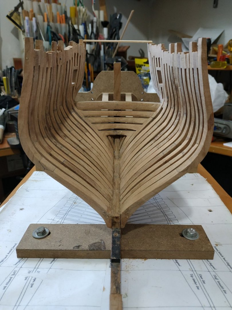
Finishing side framing and Fairing same:
Just 2 short paragraphs and little explanation for what turned out to be a long and frustrating stage.
This stage includes the forming of the stern lights (window).
Position, angle and size from the framing plan.
The upper part of 1st aft cant needs to be cut off at the appropriate height (cutting a part off the hull is always traumatic for me).
An extra “limb” attached to the fore side forms the fore side of the window-the other (aft) side is one of the “fillers” that sit on the counter frame.
The upper cant frames learn forward-this slopes back and 2nd cant frame at an angle therefore cut as a blunt-ended wedge.I decided not to glue in place yet so that I could build the window on the plan before fitting.
This,like the other fillers, follow the line of the aft cants but as no patterns are available, I used wide blanks (15mm) and for the most, kept them the same thickness of the other cants.
The aft side of the window sits on the counter frame, parallel to and at a distance shown on the framing plan. The angle of the sills is also shown.
The position of the sills marked with on the side frames-
Not clear from the plan the thickness of sills, so I guessed at 3mm lower and 2.5mm upper.
The TFFM shows a “v” shaped mortise for lower with a variant for upper joints.
I thought I’d be clever and use a “V” milling bit to a depth of 1.5 and widen the V with the chisel but with my defective thumb I found this impossible. So I cheated and used a square ended bit with a width of sills.
Forgive me.
The other fillers caused me more difficulty than anticipated.
Balanced on the thin counter frame they needed the small fillers at the top to be held in place while drying. Keeping alignment was anticipated thus the excessive width of the blanks.
There is also some variety of thickness-again referencing the framing plan.
Angling correctly the “feet” was fiddly and lack of patience on my part (fatal for a modeller) caused frequent dislodging of bits.
Also an overly tight wedge between two tops, caused one of the counter frames to part from the wing transom.
This necessitated unsticking the adherent bits, realign the counter frame as before, and start again.
The PVA glue has a fast grip, but be left overnight for good adherence.
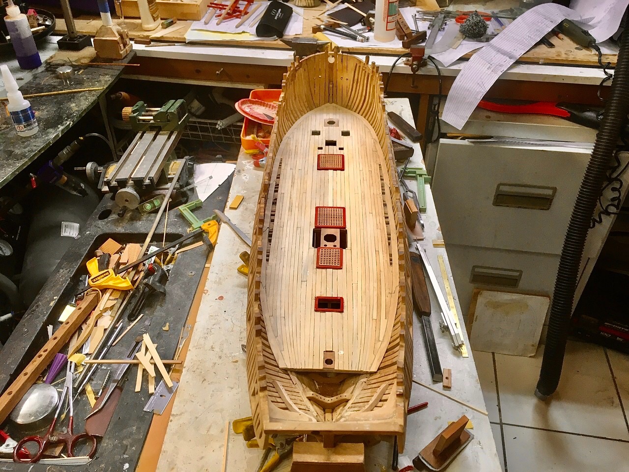
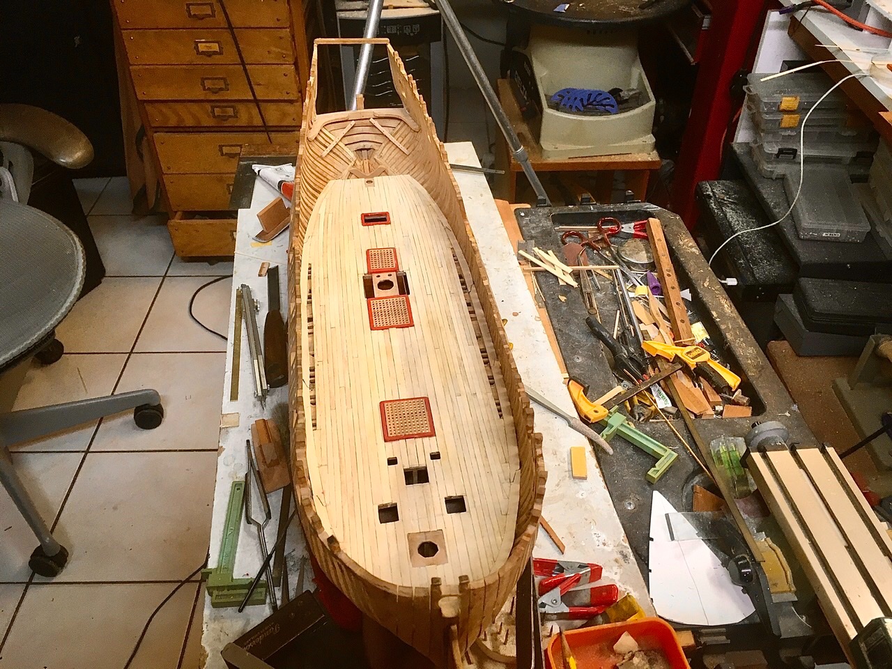
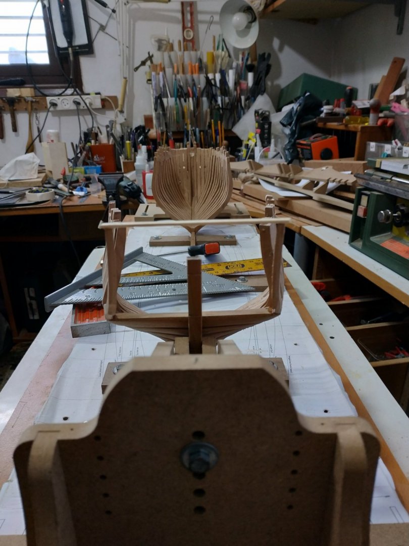
Fairing:
Because of the extra wide fillers, window frames and sills, lots to take off. So I used the hand band sander for these.
The rest of the sanding was time and effort and I’m sure any modeller is familiar with this.
Just to emphasise the need to support the work -by hand and clamped beams.
I again left the lower external fairing until keel more stable.
These stages have taken me more time and frustration than anything so far. Perhaps the designation ”filler” suggested something simple and I didn’t give the attention and respect needed
I’ll try not to repeat this mistake.(Modelling is like life-nothing is as simple as it seems)


- bruce d, KARAVOKIRIS, muratx and 9 others
-
12
-
14 hours ago, dvm27 said:
With Sea Watch books no longer selling plans for the Swan class we have decided to provide them as a free download from our website
http://admiraltymodels.homestead.com/Plans.html. Feel free to take use this set of plans if building a Swan class ship model in the future. Be aware, however, that the sheet with the sheer, half breadth and body plans need to be printed commercially due to their size. I have had no end of problems getting these plans printed to spec in the past even though there are scales printed on it. Therefore, we are now providing them as a free download with the caveat to check them very carefully after printing. The best advice I can give is to make sure the distance between perpendiculars is 96' 7" (scale) or 24.15" full size.
For those who have purchased Mylar plans in the past from us there should be no problems as they were checked and dimensionally stable. But David and I feel that we can no longer charge for plans for which we have no control over the final product. With so many of our Swan books having been sold over the years we didn't want to leave you without any options for producing plans so this is the best we could come up with. Thank you for all your support over the twenty years we have tried to provide the best product possible.
We are hopeful that we may be able to conduct a workshop late next year but, like everything else in this strange time, we shall have to wait and see.
Stay healthy and best wishes from David and I for a better 2021!
Thoughtful and generous . I paid for them some years ago, but appreciate that this may encourage others to join the "Swan" voyage of discovery
- Rik Thistle, druxey, thibaultron and 3 others
-
6
-
43 minutes ago, Jaager said:
If you do not contemplate manufacturing your own metal tools, then neither a mill nor a lathe will prove to be an economical expenditure.
The parts of a hull that they will produce are relatively few. If you are going with a larger scale and mostly leaving the outer planking off, there may be more work for a mill.
The probability is that both tools will mostly sit, looking for a job, if it is only wood that they will be used on.
For fabricating metal tools, both are vital.
A Byrnes table saw, disk sander, and a drum sanding table and an accurate drill press come far ahead of these two tools.
Serious POF probably means that you will have to be your own sawmill. In which case - a big boy bandsaw and Byrnes thickness sander slip in ahead of them.
I beg to differ. I have a proxxon mill and it is in constant use , even before I started POF/scratch.
After some short learning curve, it gives quick, accurate and reproducible results. Its limits are the need for variety of bits and experience of user. These can be overcome with more experience, inventiveness and some money.
The aforesaid does not detract from the other tools mentioned.
Start young and get your money's worth.
-
On 12/14/2020 at 12:12 AM, Kevin Kenny said:
Just the last two deck strakes to install. Thank goodness the deck covers up my inaccurate carlins. This will not happen on the main deck. One of the main reasons for installing the full deck is to learn from my mistakes and make sure when i lay the main deck it will not have these errors in it. Experience is the best teacher. I have learned so much. This build is the best teaching course one could attend in model building. I am so appreciative of the time David and Greg put into this practicum.
Beautiful. You are an inspiration (and help to make my poor effort possible)
Have a great holiday
-
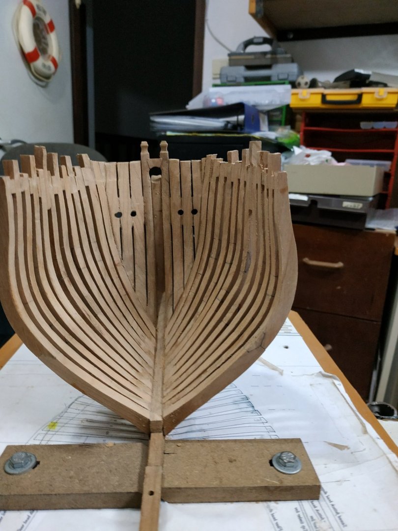
Framing the stem/side Counters
(TFFM mentions a 9th port- at present this would be an unnecessary complication and I’m still on chapter 2.)
The practicum gives a detailed explanation which encourages reading to the end. I don’t really understand, so I turn to Kevin’s video-he says something similar, so we go ahead and make the pieces.
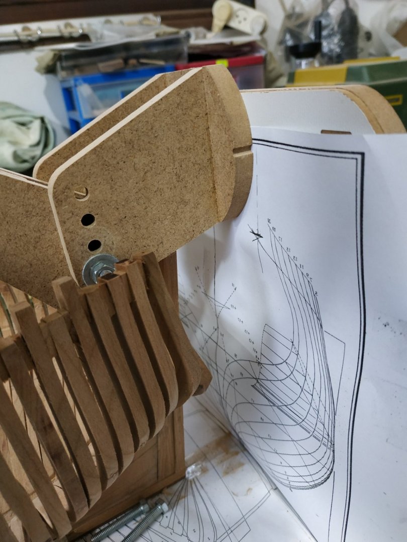
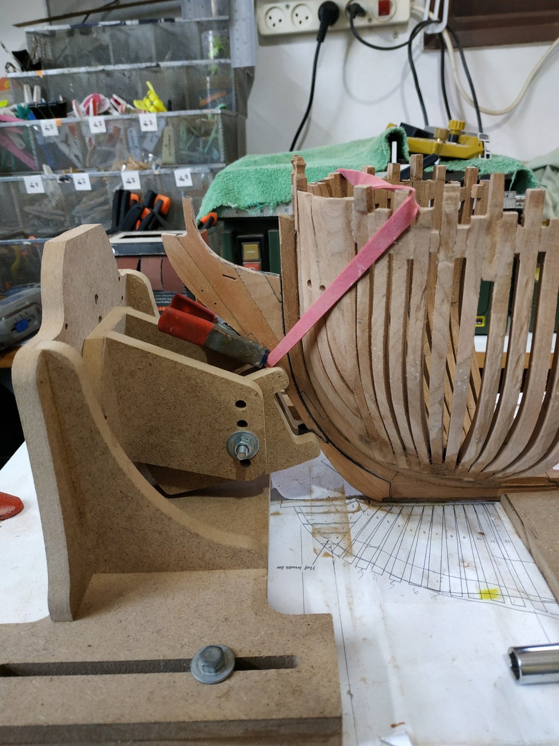
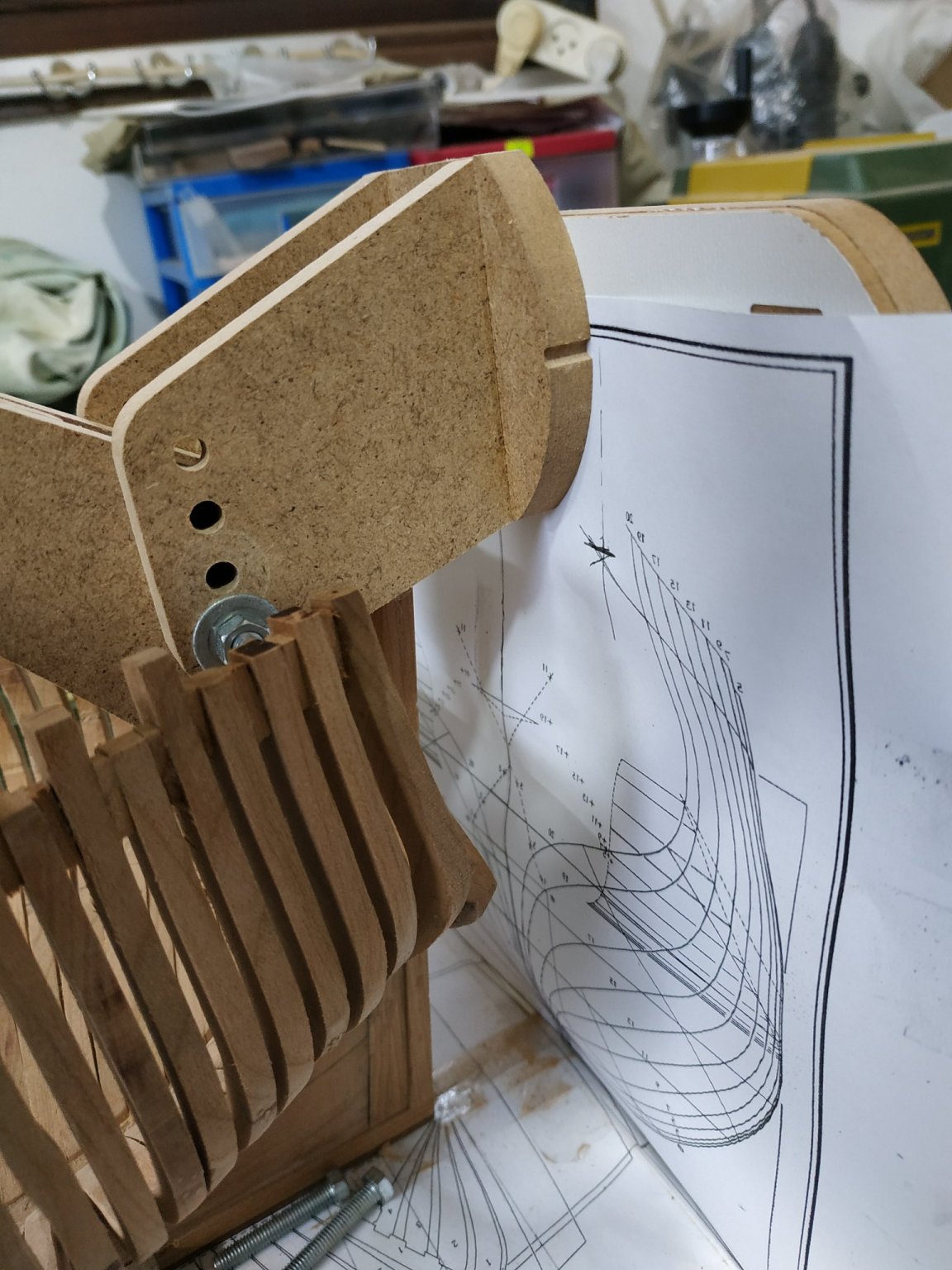
Before attempting to make the piece, a jig of some sort needs to be made to align and support the aft end, at the correct height, and angle so the pieces are separated by the correct distance. Additionally, the stem needs support to maintain the vertical 90deg position.
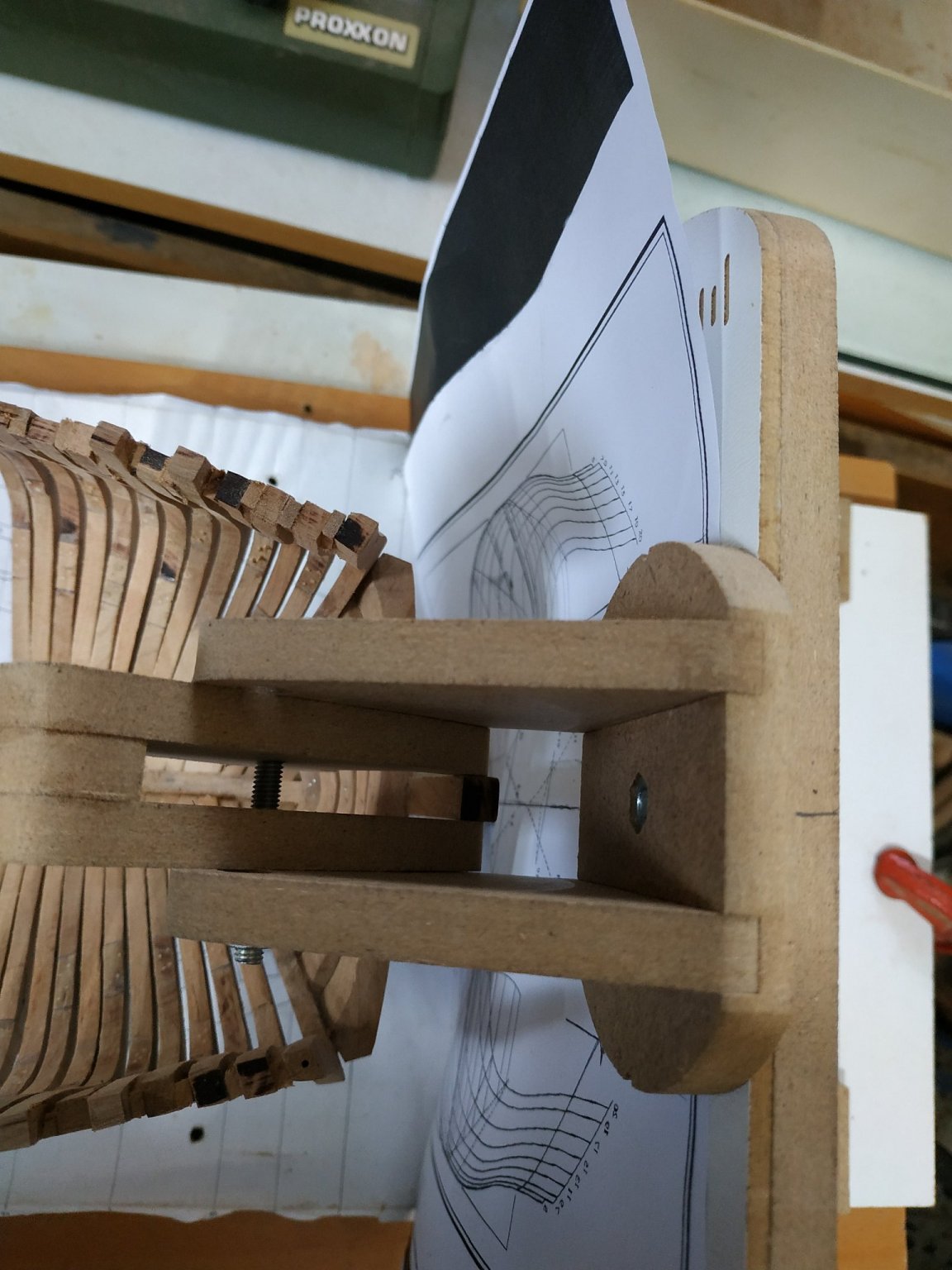
The hobby building slip has a vertical plan holder. By adding the stem clamp to this (with the body plan underneath)it supports the stem, the new side counter while controlling its position and angle.
Instructed to draw line parallel and 3.34cm aft of AP line on the breadth plan. This intersects with the end of the timberline and is aft position of the pieces and the mark for the vertical plan holder.
On the body plan, vertical lines, 3.9 cm either side of the midline are drawn and the point this intersects with the height of timberline, is marked.(A simple drawing on the page makes this very simple).
Fortunately the book gives a (correct 1/48)scale image because I spent a half an hour searching the plans.Note this is for the starboard side - it took me a while to be sure of this.
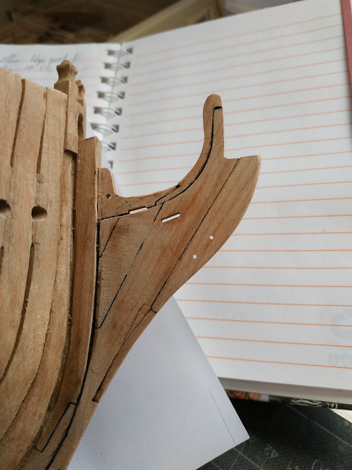
Photocopies for templates, 7.95mm blanks, and using the sanders, made the pieces in 2 stages ie dimensions.
The timber line is marked on the pieces and the inner aspect aligned to the mark on the plan (again the drawing in TFFM is self explanatory)
The “foot” needs some refining to accommodate angle of #1 cant and slope of wing transom.
This is (if only temporary)a fragile joint so I used 5min epoxy while the plan holder supports the end and vertical plane is maintained.
An additional measure is used- 9.22 cm between the 2 upper knuckles-this is checked while glue is still semi-flexible.
Finally, if sure OK, a spall or beam is temporarily stuck to the tops for additional stability.
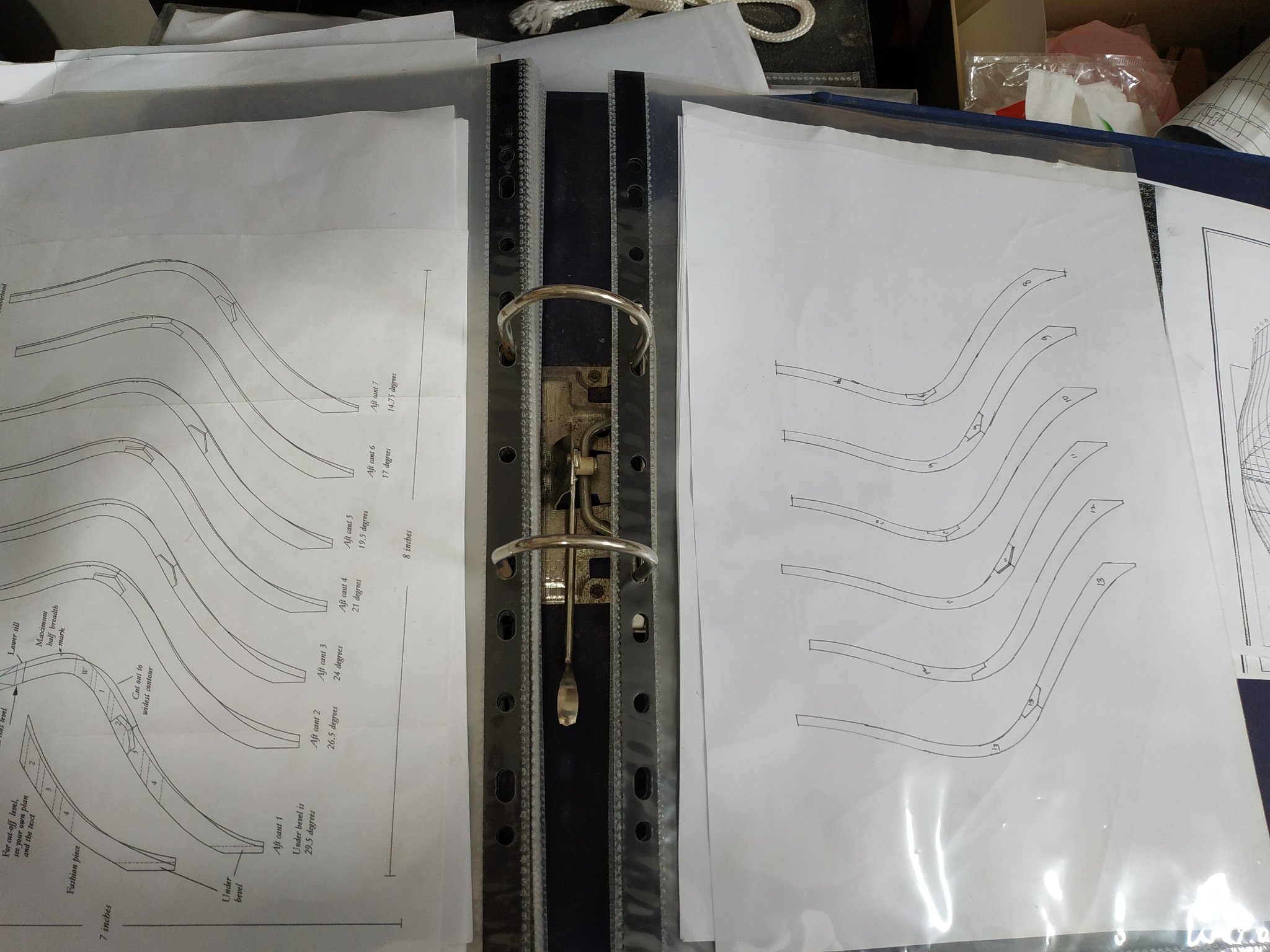
PS accumulating lots of photocopies of part plans/templates. Filing them in separate plastic envelopes in a file makes for order.


- captain_hook, dvm27, tlevine and 4 others
-
7
-
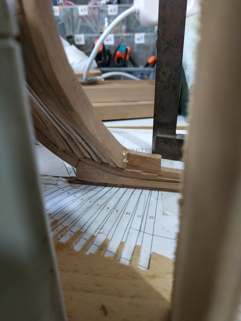
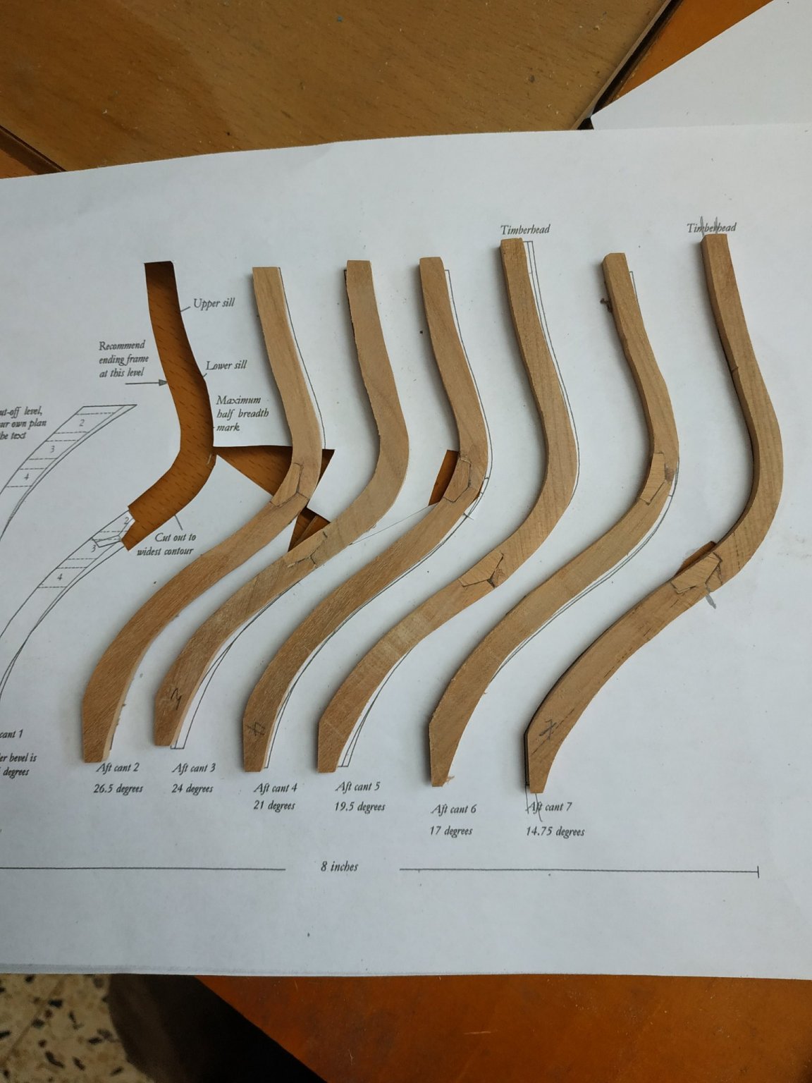
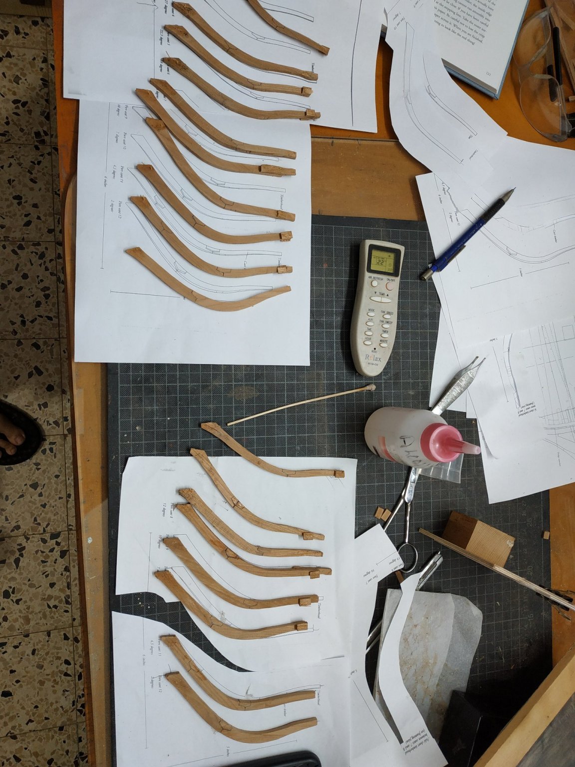
Aft cants #2-13 cont.
Finishing making of the aft cants. More adept and less removals and repositioning . ( ? is this called RECANTING-ha! ha!)
Regular except for #10 which as a “shift” similar to the #11 fore cant. Note the shift is directed amidships in both cases.
Also note #12 has a scarf joint instead of chock.
Also note that when trying to minimise wood waste, I layed out some templates across grain- not very clever but doesn;t appear noticeable as yet.Will replace if required when seen after initial fairing.
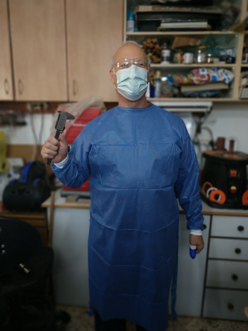
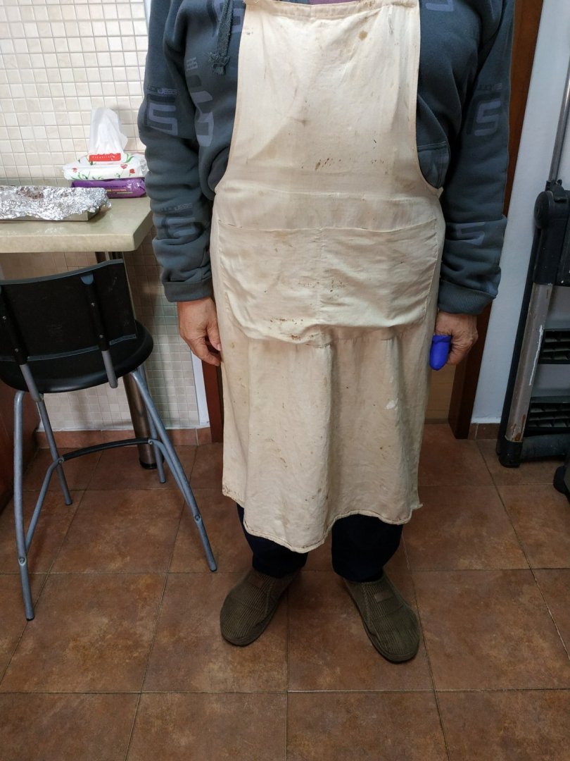
You may have noticed the horror picture of me wearing my schoolboy apron. It left my upper jumper unprotected therefor still half covered in sawdust.
The new picture is more practical and to misquote Gabriel Garcia Marquez-
“Woodworking in the age of Corona”
(ppe 2020)
Keep well and safe everyone.

-
On 12/9/2020 at 11:38 PM, Richard Feliciano said:
Stuart,
Couple of steps you might consider that helped me. I ran a centerline wire down the ship line to assure the frames are offset the same port and starboard. I also made template form at the 2nd lead line level and the top of frame level to keep the curvature correct. Check out my post today

Just catching up today. really good ideas and will try them even though I've seen the post after initial placing of my cants
-
-
On 12/5/2020 at 6:40 PM, Justin P. said:
Unless you have some reason to need a power saw for the type of work this thing targets, I would say invest in a nice manual alternative. There are some very good razor saws out there that will do the work this thing does in half the time, half the clean up and twice the accuracy.
Have several but the thin ones are "bendy". Saw one used by Kenny on video and had fantasy
-
does anyone know of an alternative to the microlux brand? I simply do not want to buy their special transformer which they say is essential.
https://www.micromark.com/Micro-Make-MicroLux-Sword-Saw
-
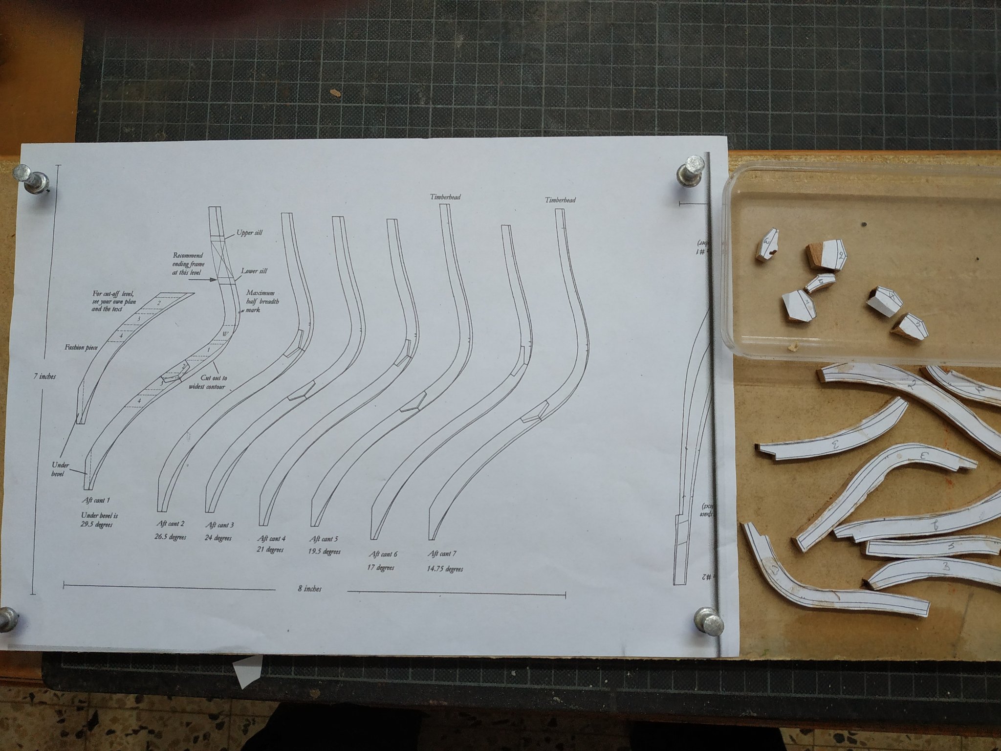
Back to building cants-this time the aft sets.
Similar principles i.e. 4.77mm wide.
This time I want to try some new ways.
My experience with the chisel was not too successful. Now with a defective digit (injured thumb) I would think nearer to impossible.
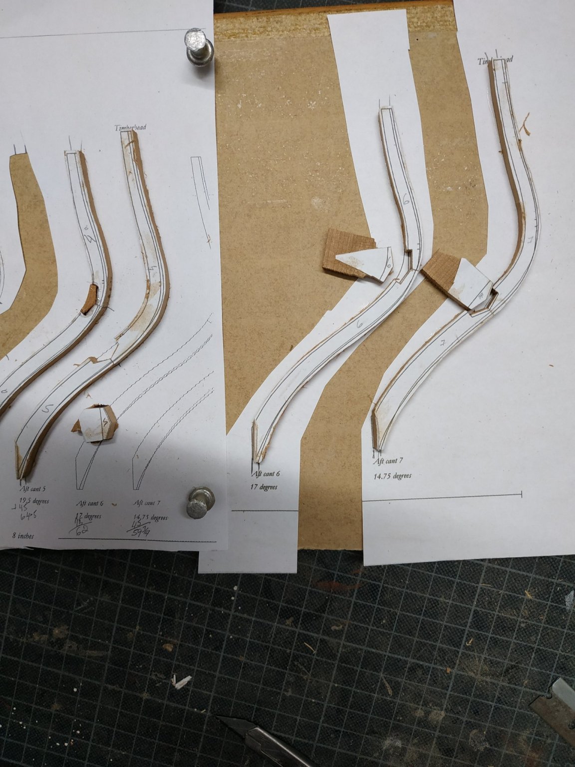
Nevertheless, I’ll try the chocks using cut out plans, jig saw and 5in disc sander.
Cutting out the timber plan separately with the chock section cut on the lines. The upper and lower timbers attached by rubber glue to another complete copy of plans. The narrowing lips of the 2 pieces have a drop of PVA and the the pieces are stable to fit the chock. A chisel blade is used to create the slight angle if the plan requires it. The is made slightly oversize, the slope of side if required and the final fit are made by removing the thinnest of slivers to size required.
Although initially against it, I tried using the 5min epoxy and it seems to work well, but it is pretty irreversible and leaves a slight stain.I don’t think it will be too noticeable when finished.
I also decided to make and fit one side at a time.
I also have left of the fairing bevels as I found that a close adherence to them when making the fore cants, created some problems with alignment.
After a try out with the 2ns and 3rd cants, it seems as if the upper timber of both 1st cants are incorrectly placed. I had broken the starboard one, twice already so made a new one. The port side was separated and adjusted-the tips of the wing transom protrude but I checked it with a plan cut out and it is ok. This may have a function which I’ve forgotten- I will have to wait and see. Greg mentions this is like a chess game in terms of planning ahead, but I did not expect such an innovative opponent !
PS In my first year of secondary school (age 11) we had a weekly woodwork lesson. Our parents had to buy an appropriate work apron. My dear mother kept mine for the next 40 years and returned it to me so I can now use it for its intended purpose.


- mtaylor, druxey, garyshipwright and 4 others
-
7
-
I only break the ones I have least of!!
- Canute, reklein, Keithbrad80 and 4 others
-
7
-
-
-
-
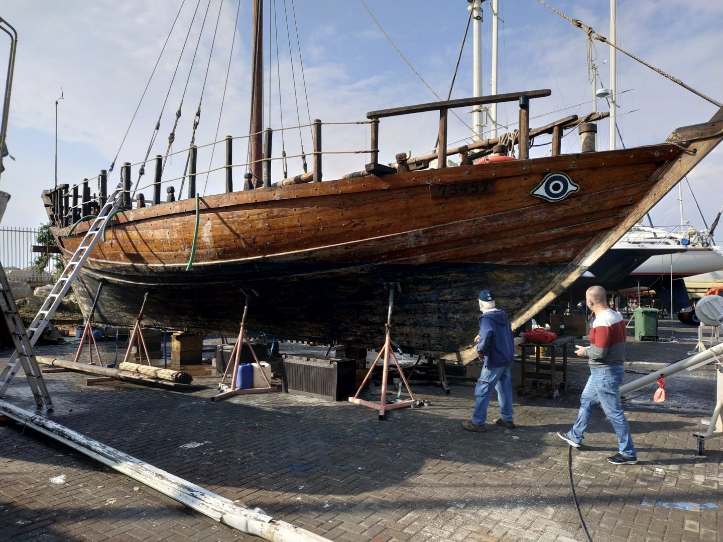
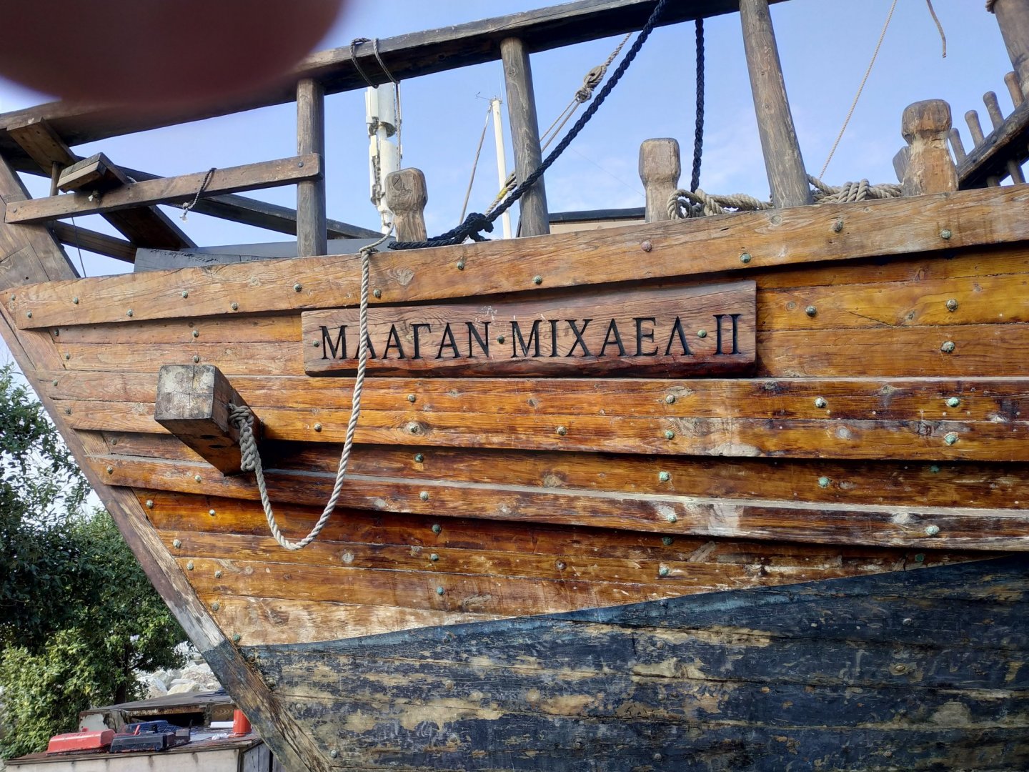
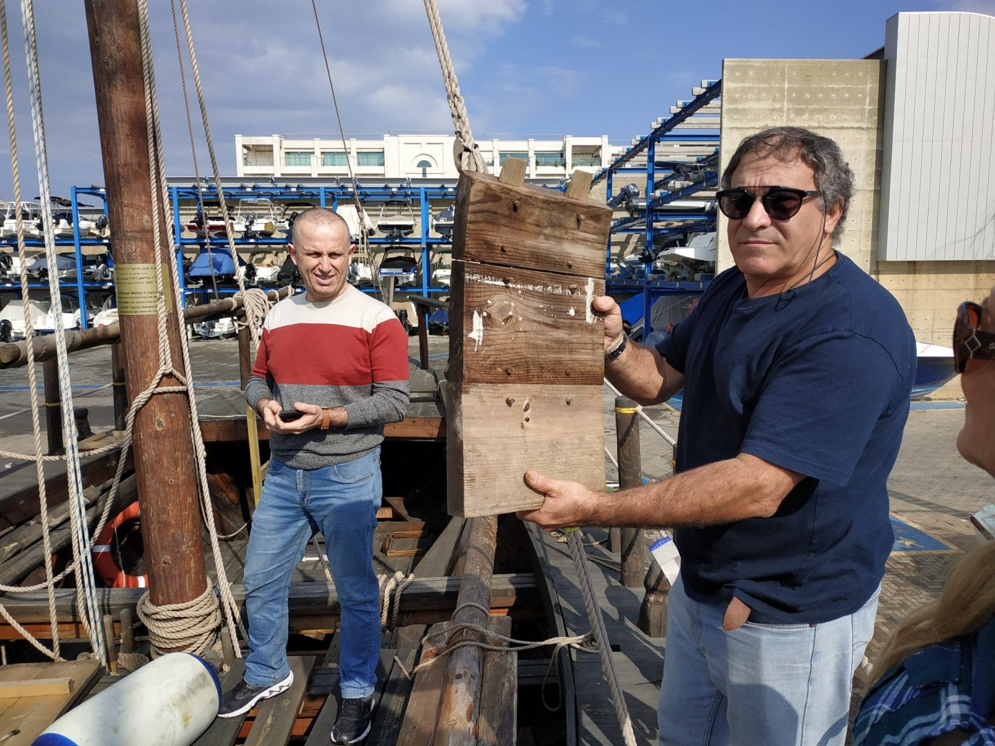
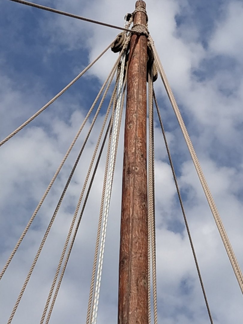
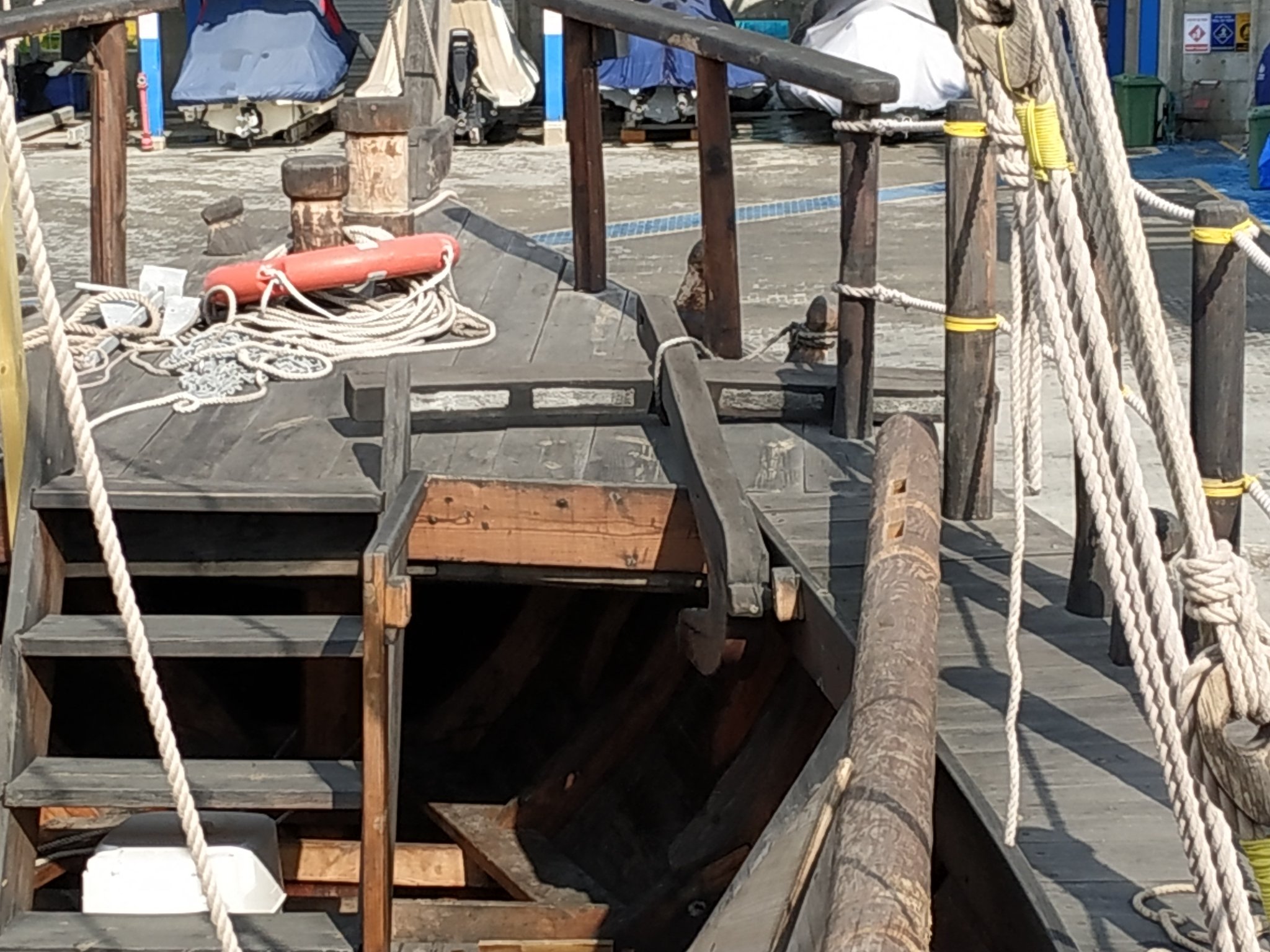
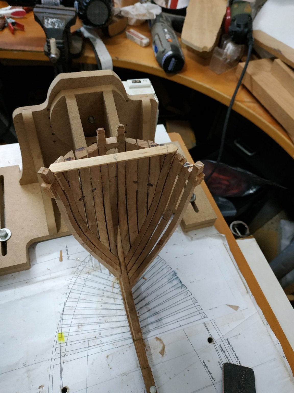
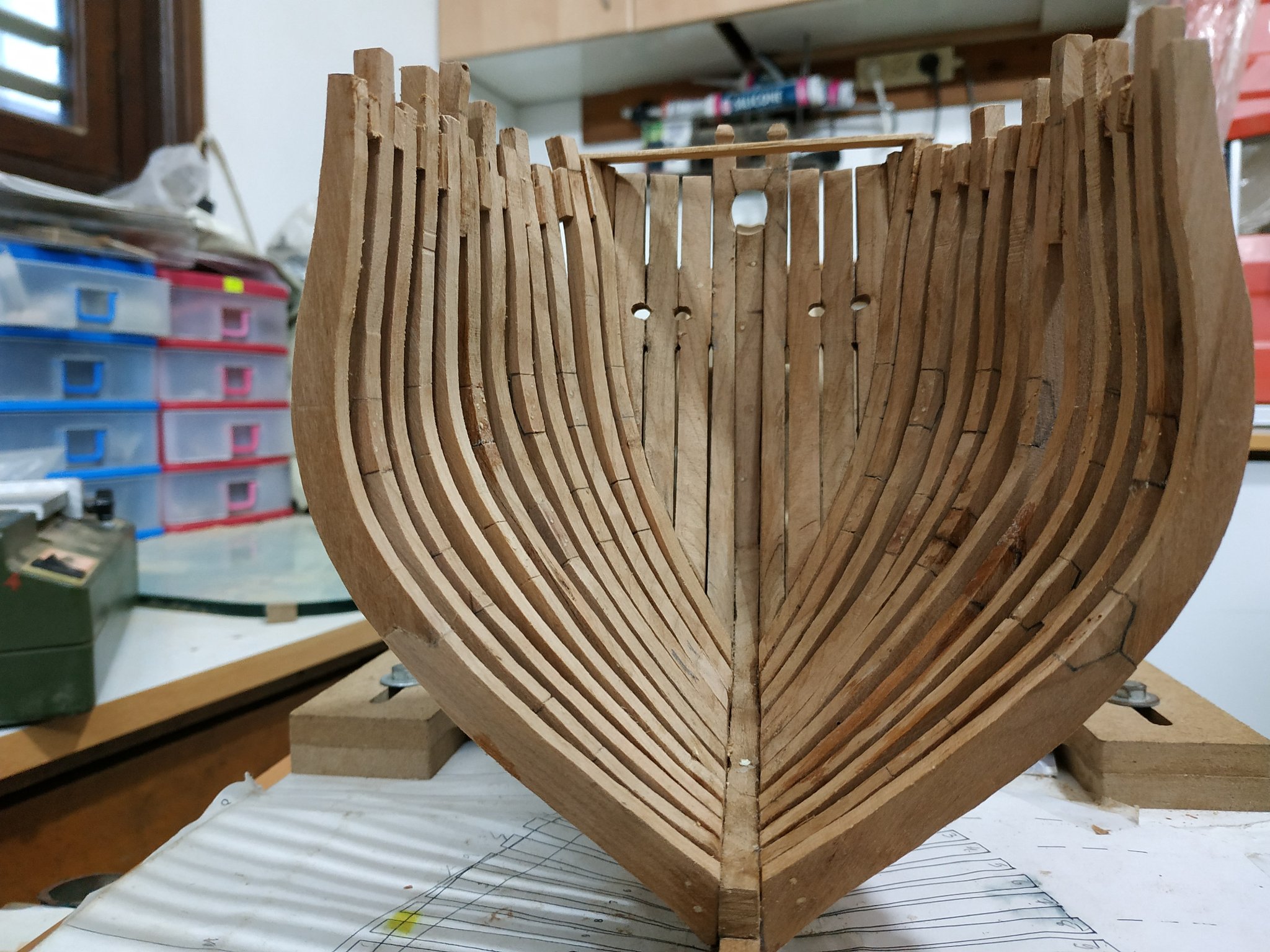
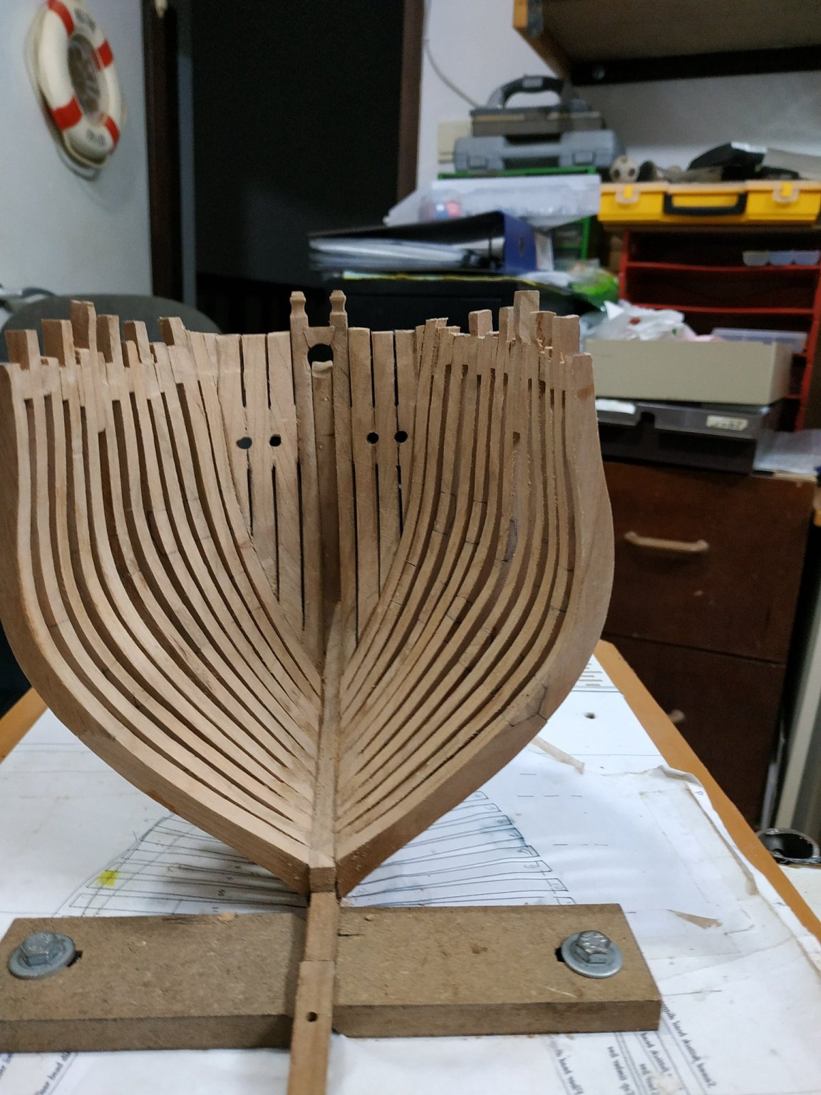
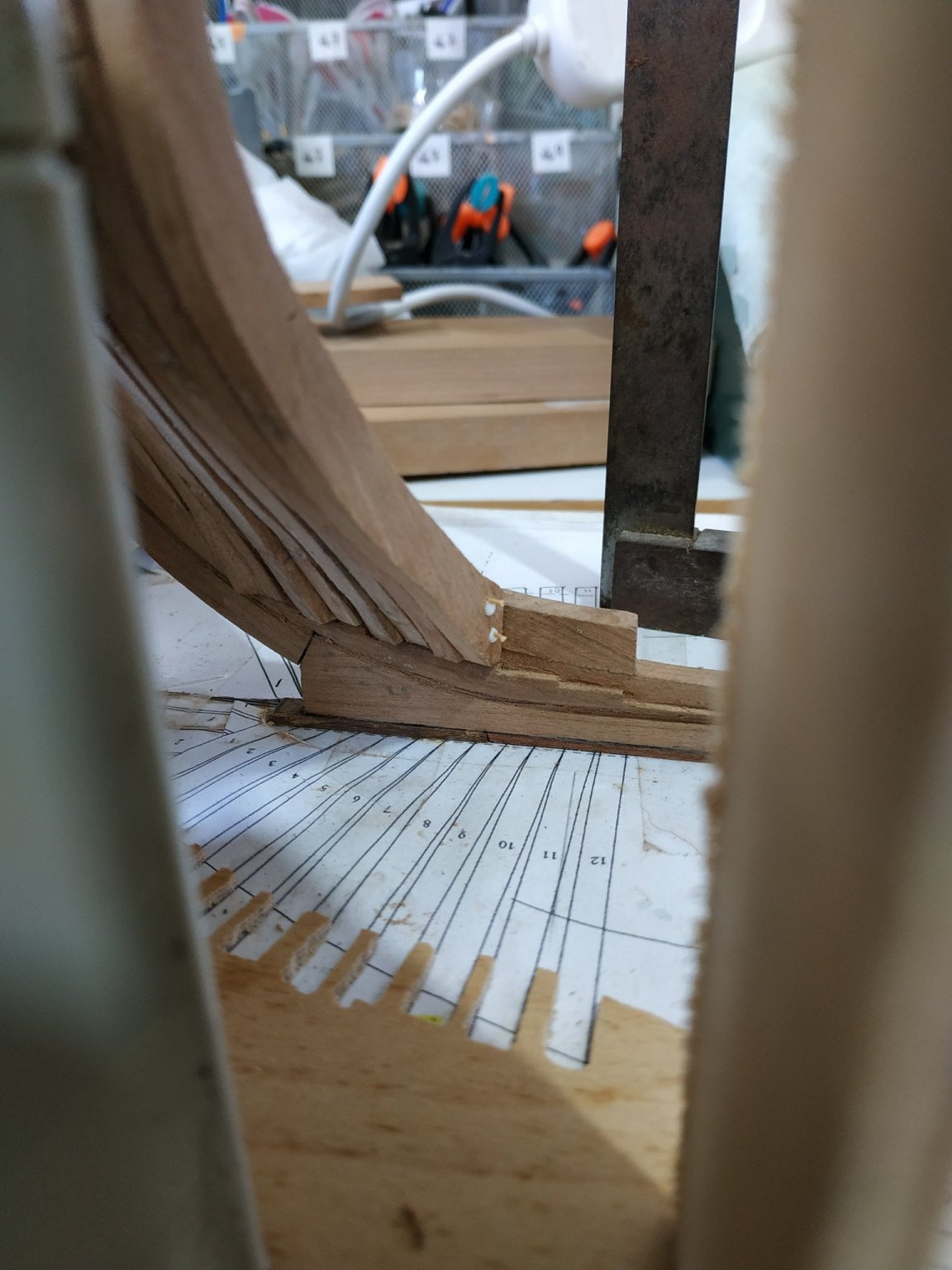
Last friday, a small group of us had the privilege of visiting and receiving a first hand explanation on a replica of a 2500 year old boat.
The technical details show these were not primitive but rather advanced designers and craftsman.
For me personally, it closed a circle as I saw the original under preservation treatment more than 25 years ago, along with my friend and mentor who built the first model of this most important find.

.thumb.jpg.5fee1de1e1f312723ebe6a69a60a2695.jpg)
- Harvey Golden, mtaylor, jchbeiner and 2 others
-
5
-
-
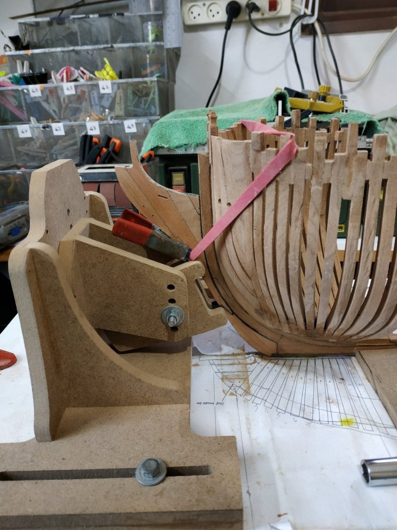
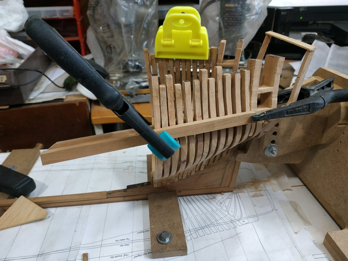
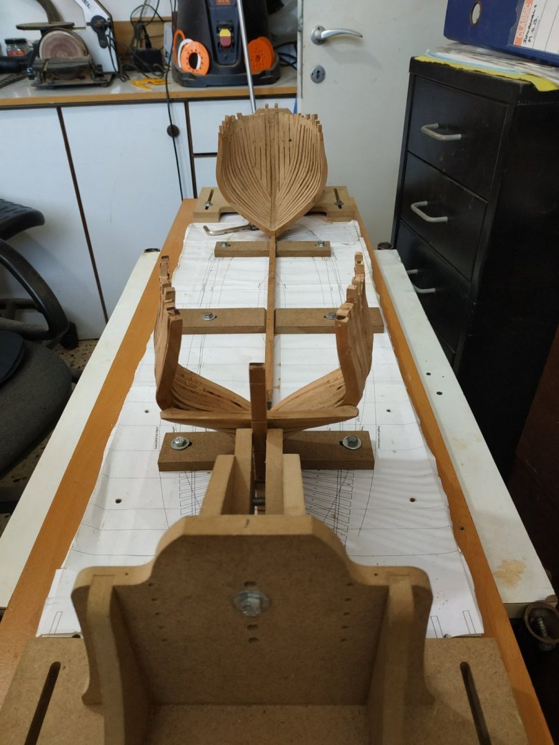
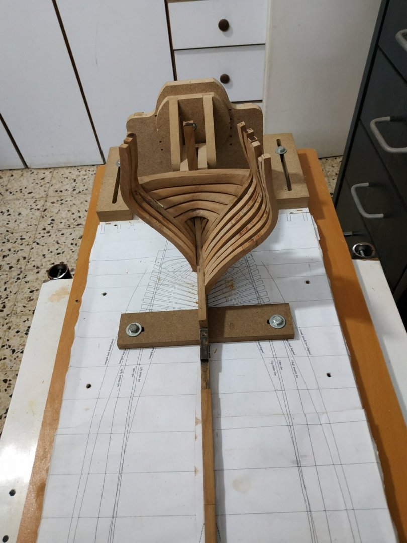
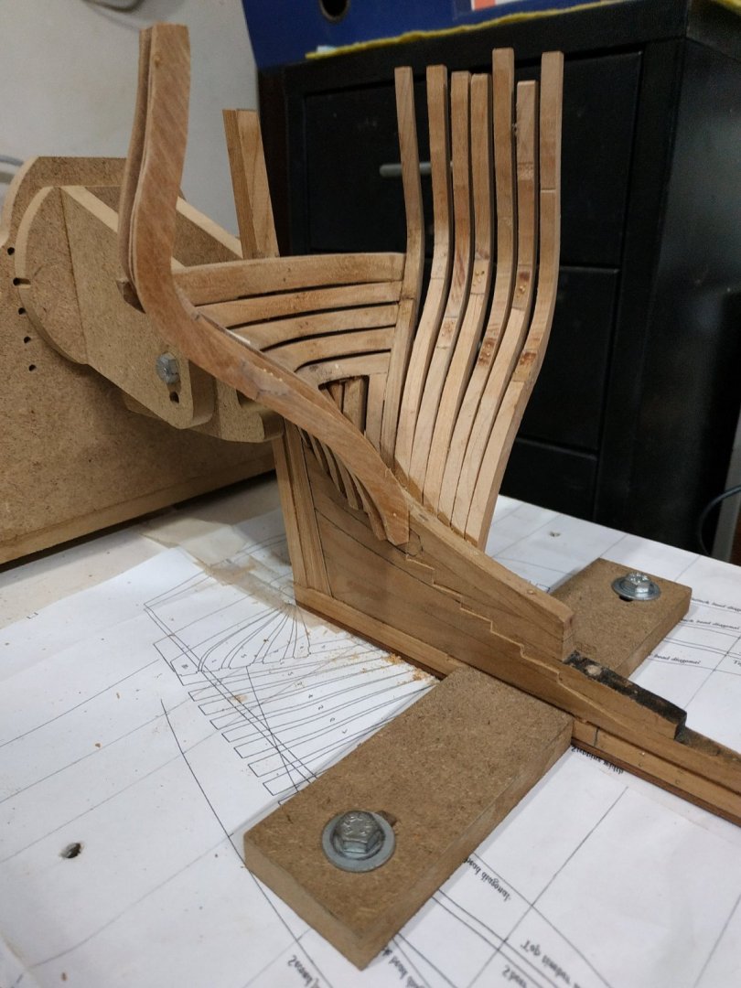
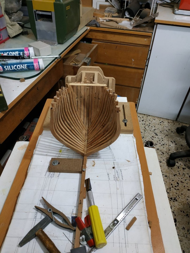
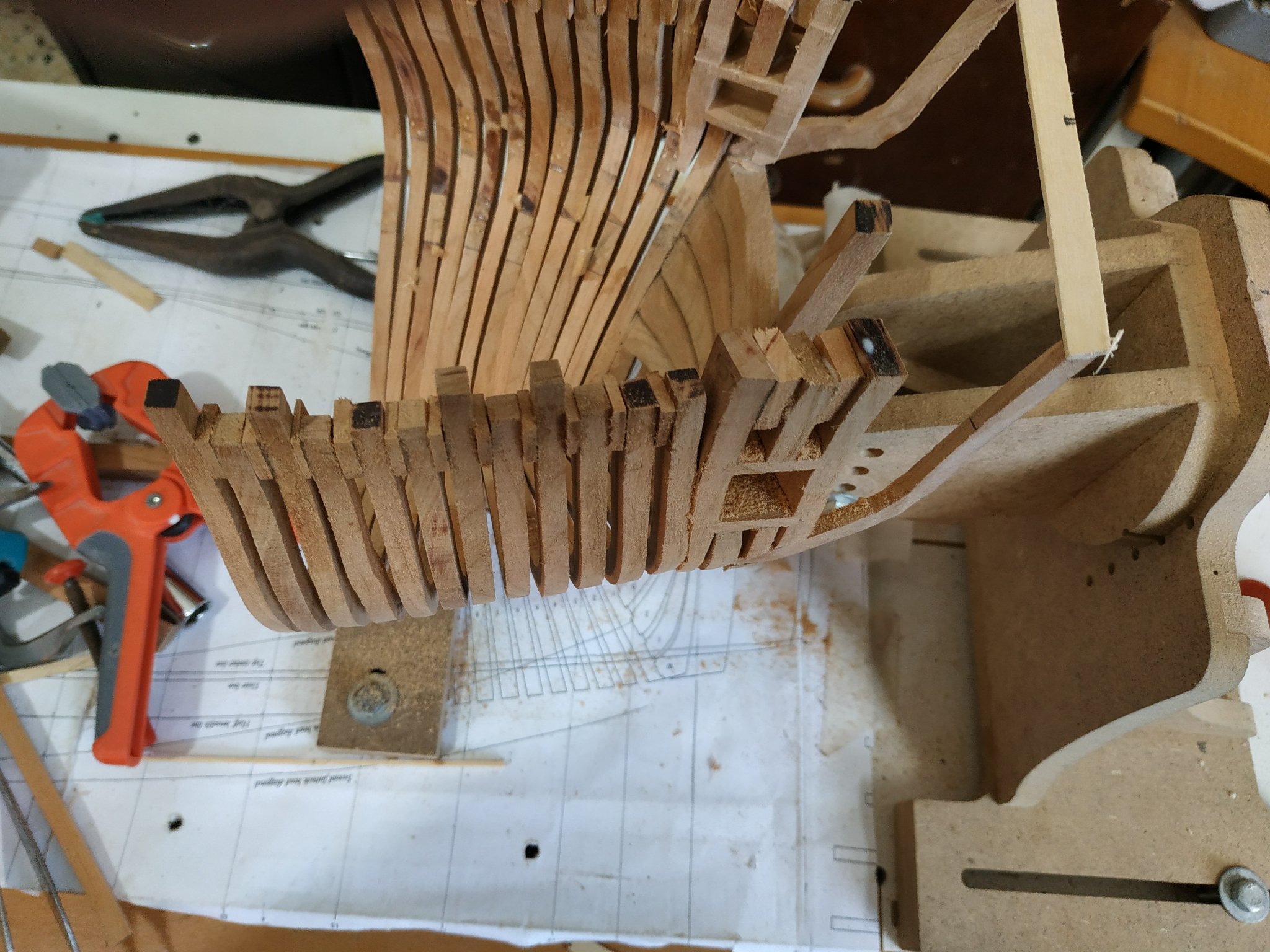
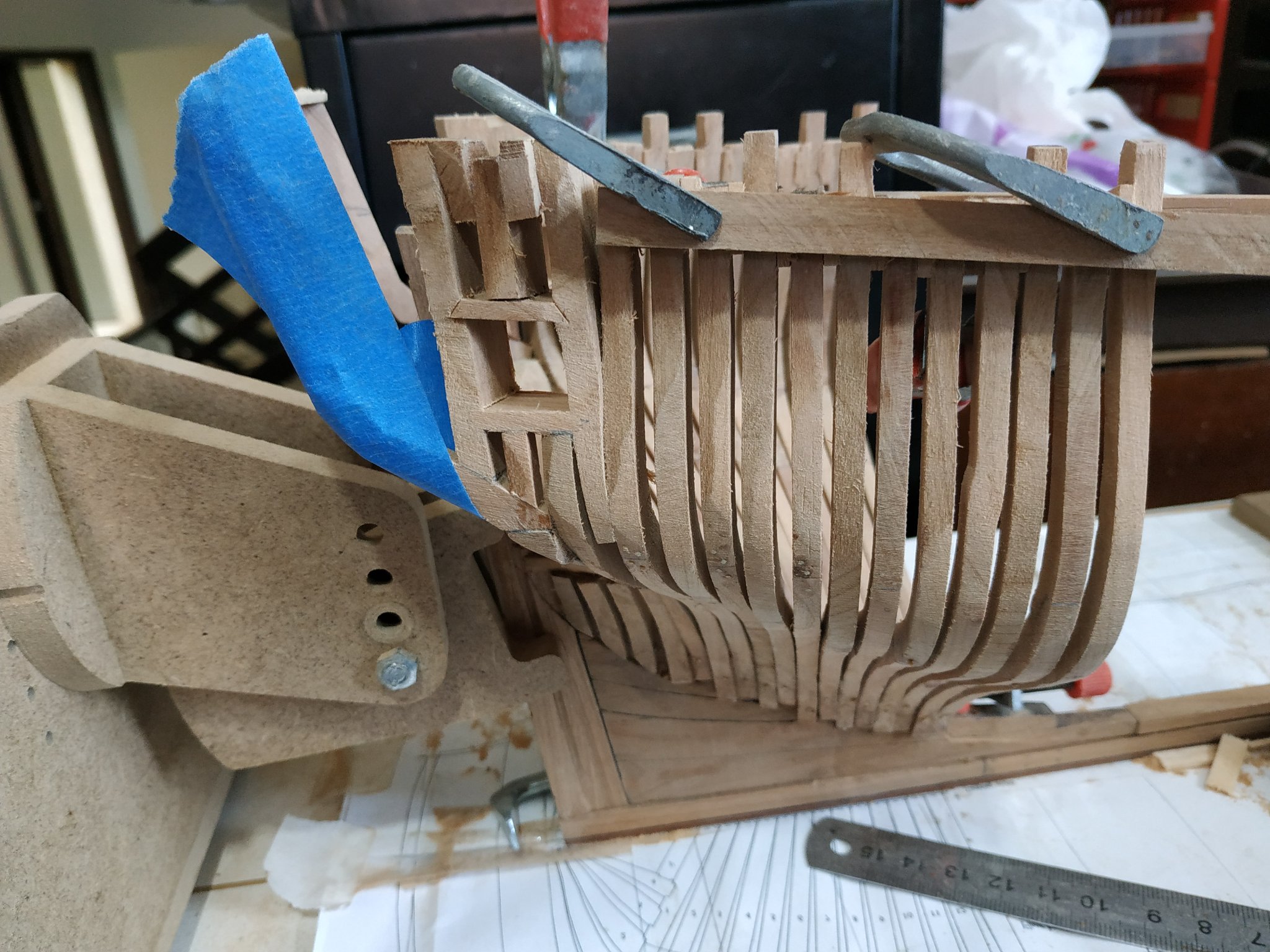
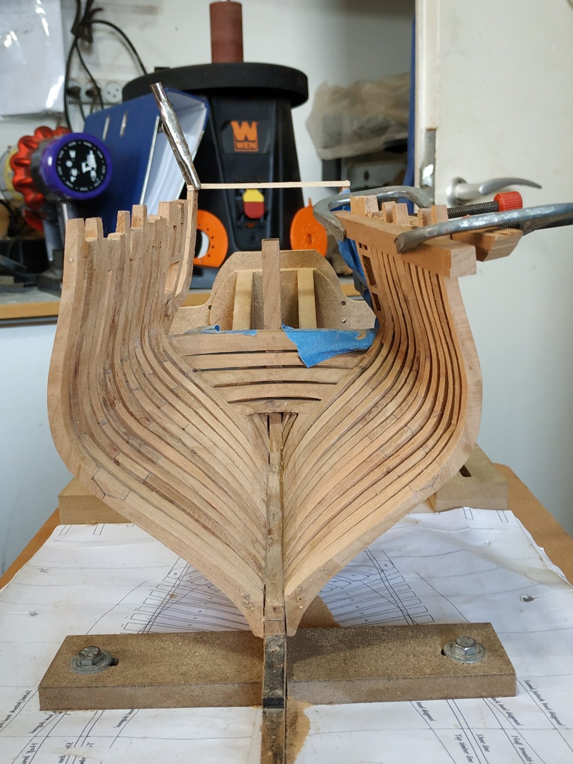
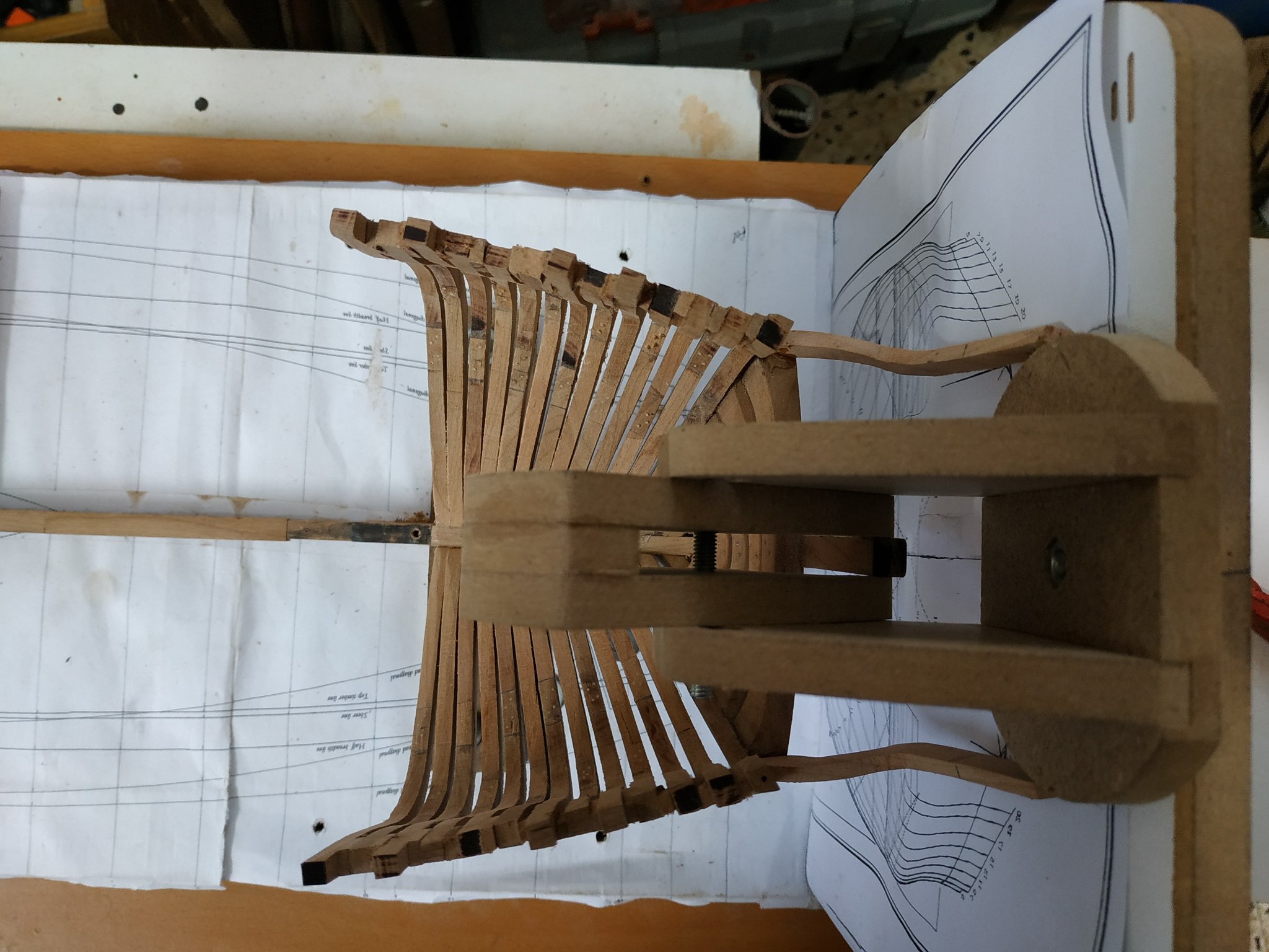
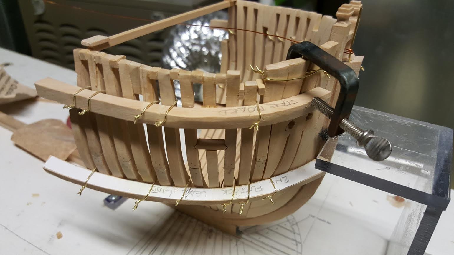
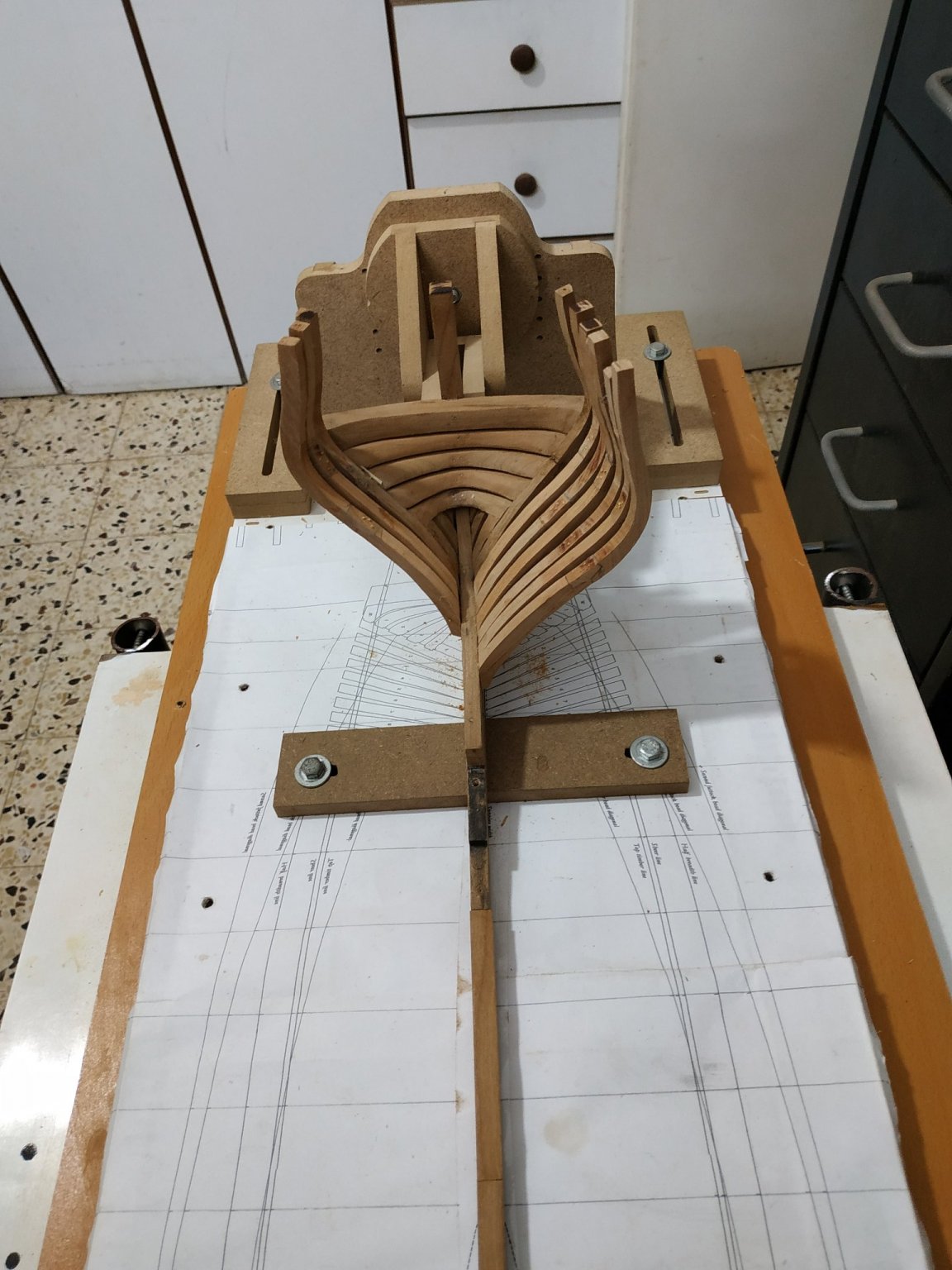
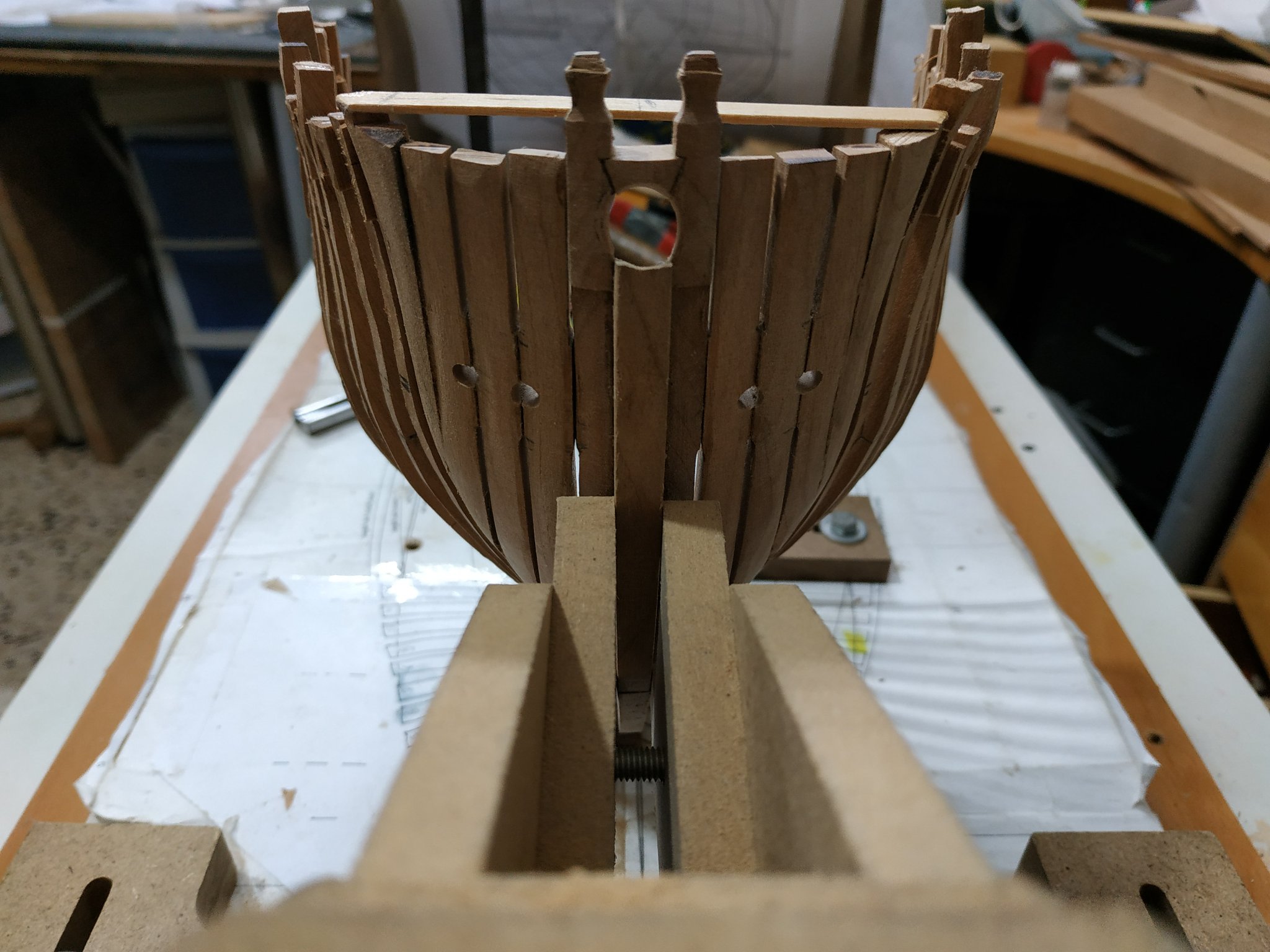
Place some crude spaces at level of timberline. Intention to remove them later, but give stability for fairing etc
Not having use of thumb is somewhat restricting.
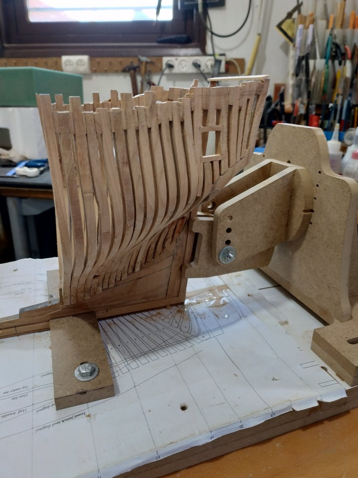
The jig reused upside down for the starboard side seemed to work ok when reset (what was the straight floor, now is sloping at timberline level) with some weights.
When the full set of cants fitted, jig removed and the result is not as good as expected.
The main problem seems to be the angle where the timber parts are glued.
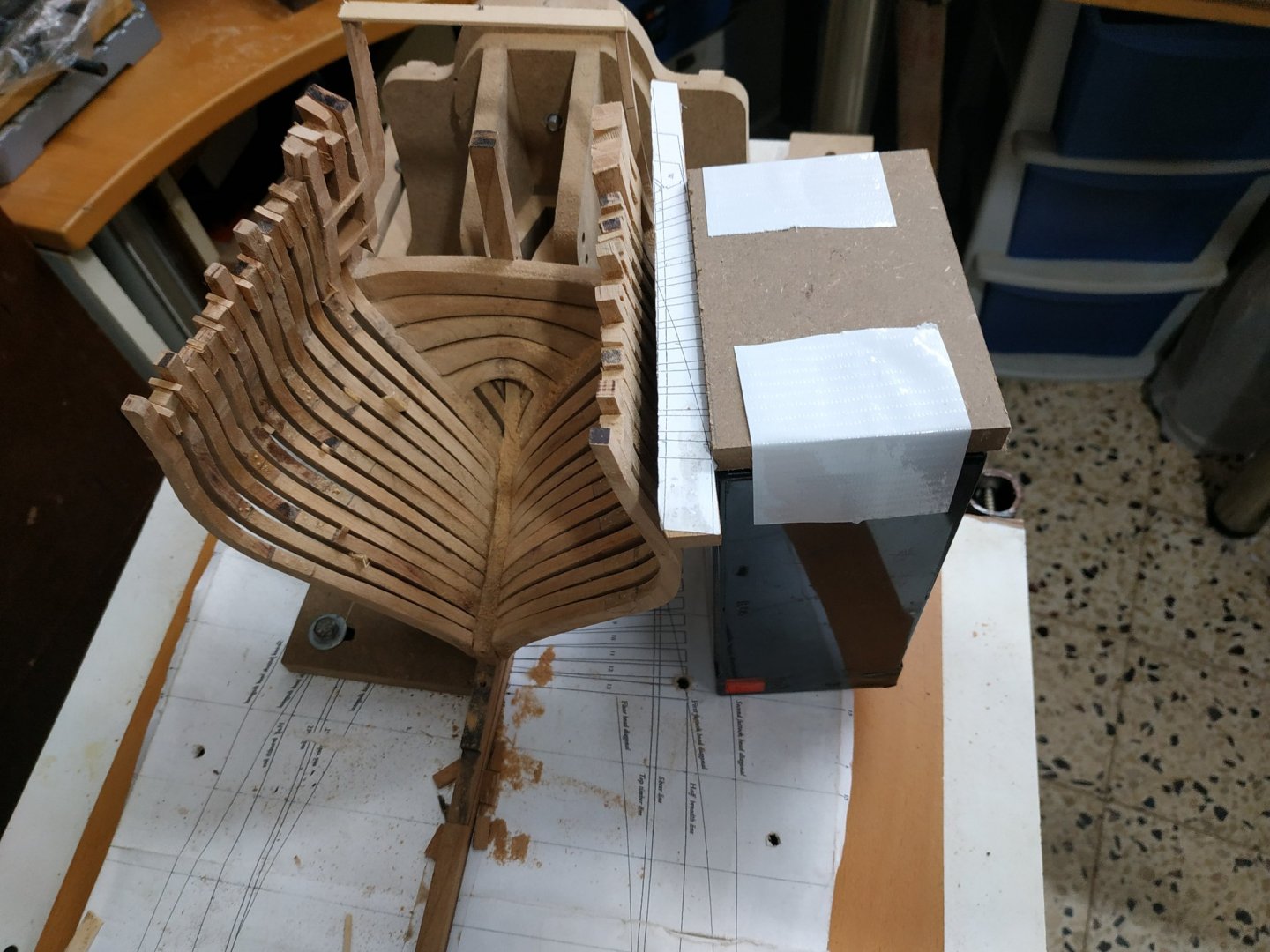
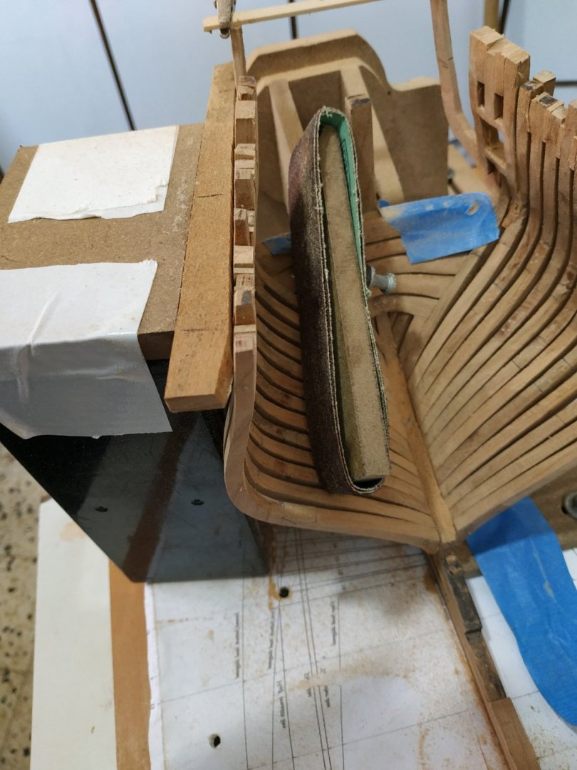
I removed a couple of the worst offenders and checked them against the printed outlines-not so easy as they obscure the plan, and the cut outs can be distorted. Opening them and re gluing made some improvement, but “gradient” between the cants, seemed excessively uneven.
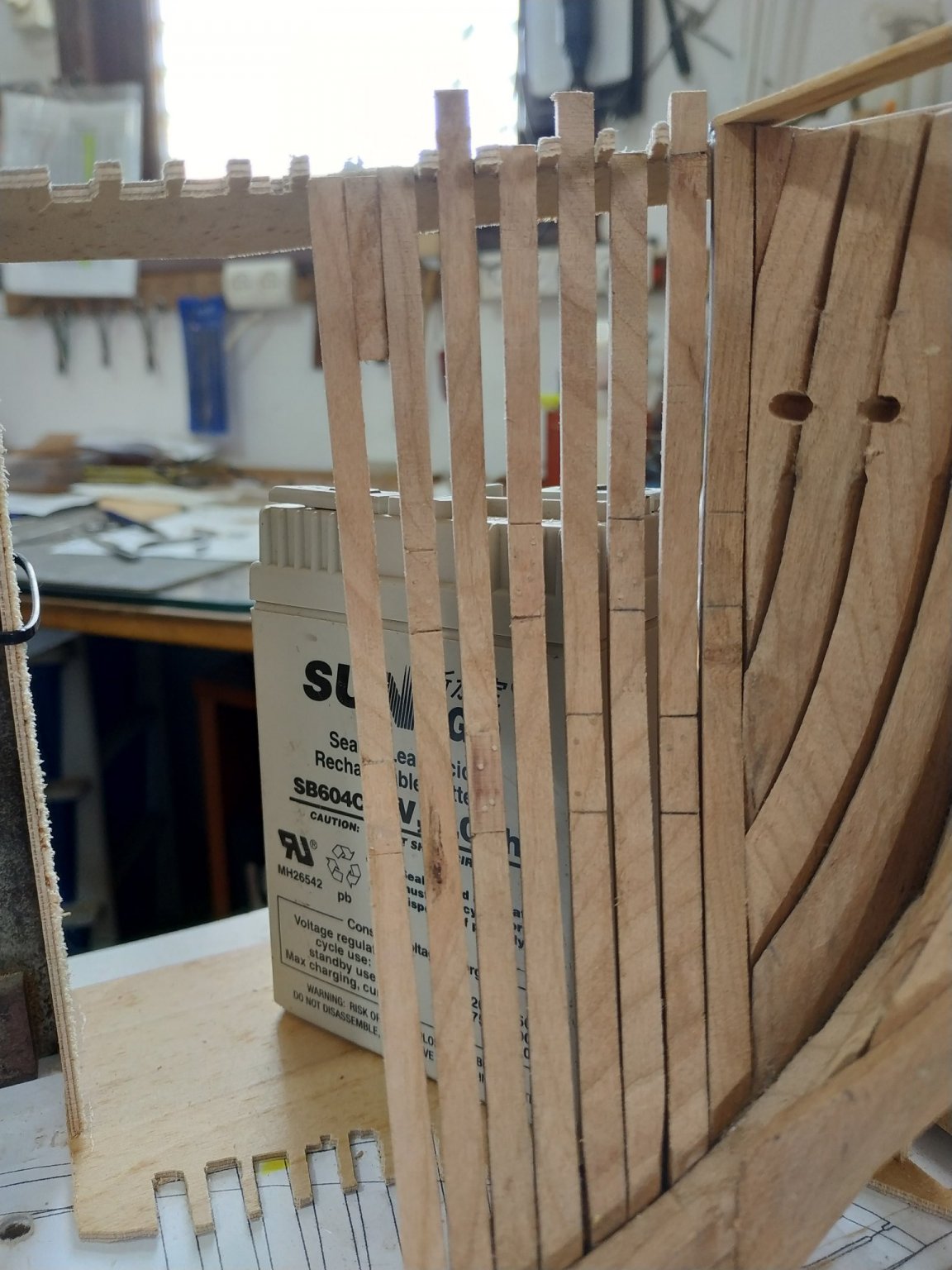
Decided to remove all cants #2to#12 and check and realign joints between timbers as required.Extending lines on the plans help this alignment.
Placed each cant in turn,checked alignment at timberline and “step” to previous(neighbouring) cant, and if still too uneven, modified the angle at the join slightly.
(the black square object is one of many old batteries I’ve collected over the years-stable,heavy and reliable rt. angle.)
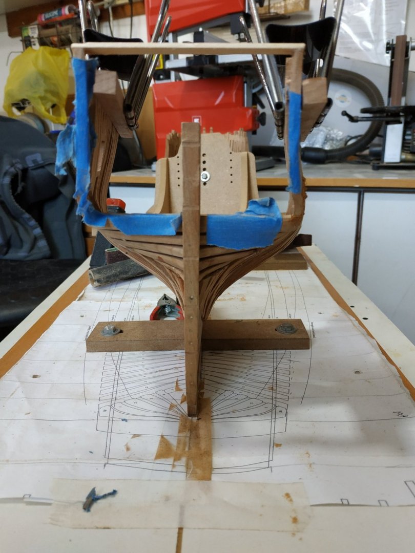
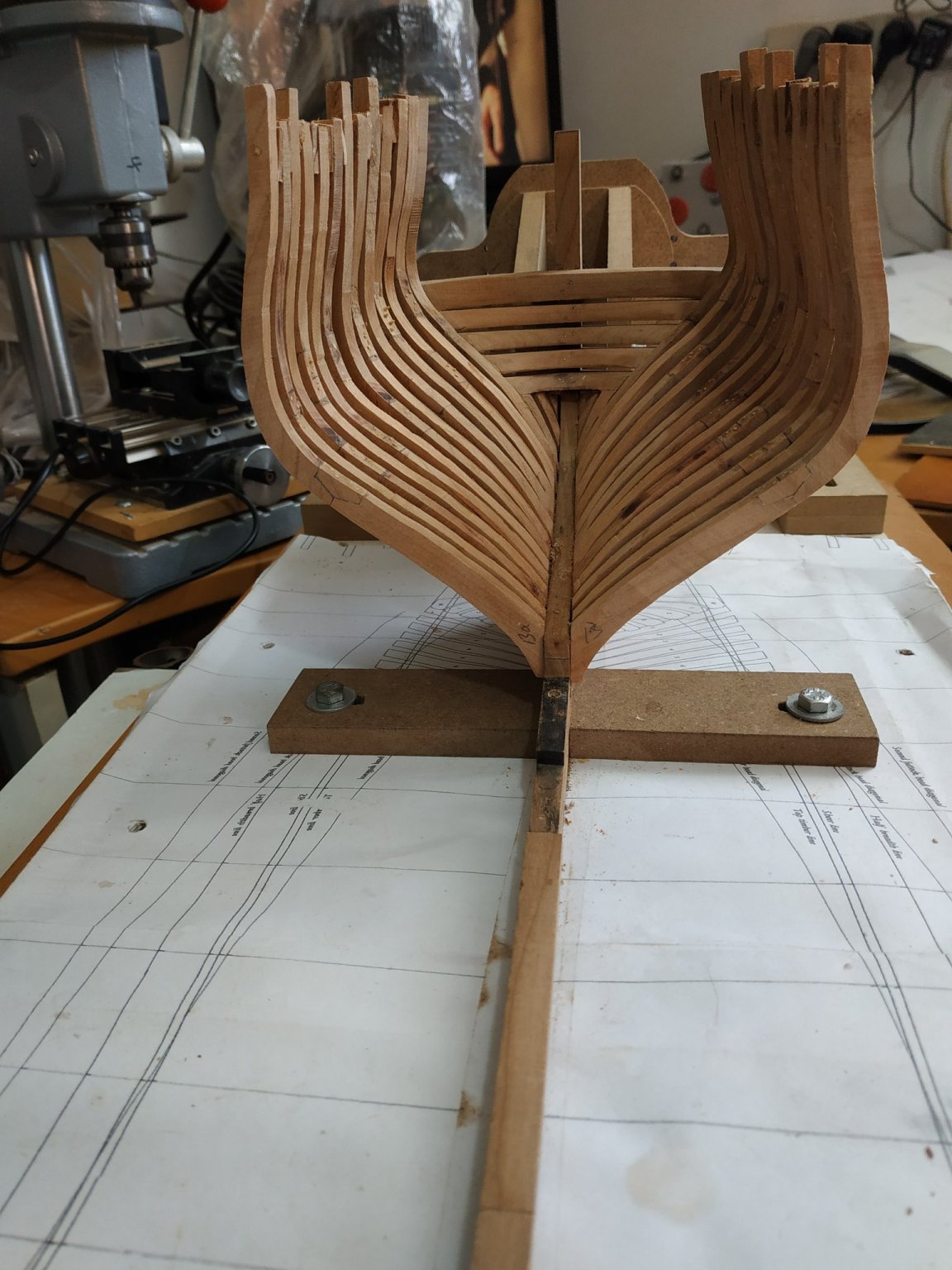
This time the result is much better.
Fairing by hand. Wands and literally by hand on inner aspect ( a broken belt sander-stiff). Much to remove but this cherry is relatively soft compared to the Pau Marfim that I used for Oneida.
Left final smoothing until rest of framing complete with some internal “stiffening”
Some of the small fillers separated and it would have been better to stable with a trunnel.
Returned to working in clinic and less time to browse the internet, so only now caught up with Kevin’s video no. 12 and see he run into similar problems. Considering the high quality of his work, I feel less inadequate. Thank you.
PS last week or two, temperatures here fluctuate . 2 days ago on the beach, today cold and torrential rain. Not good for wood or glue.
PPS Happy Thanksgiving to our American friends.


-
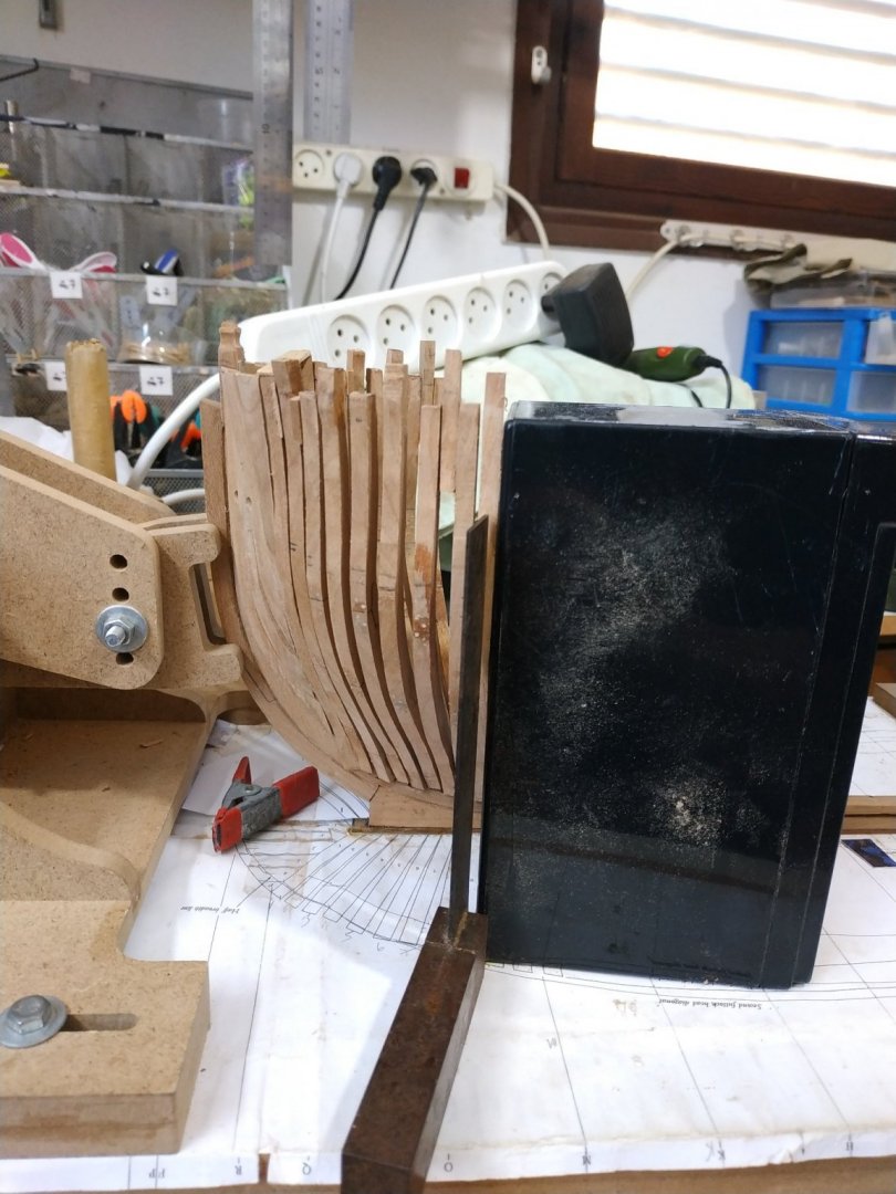
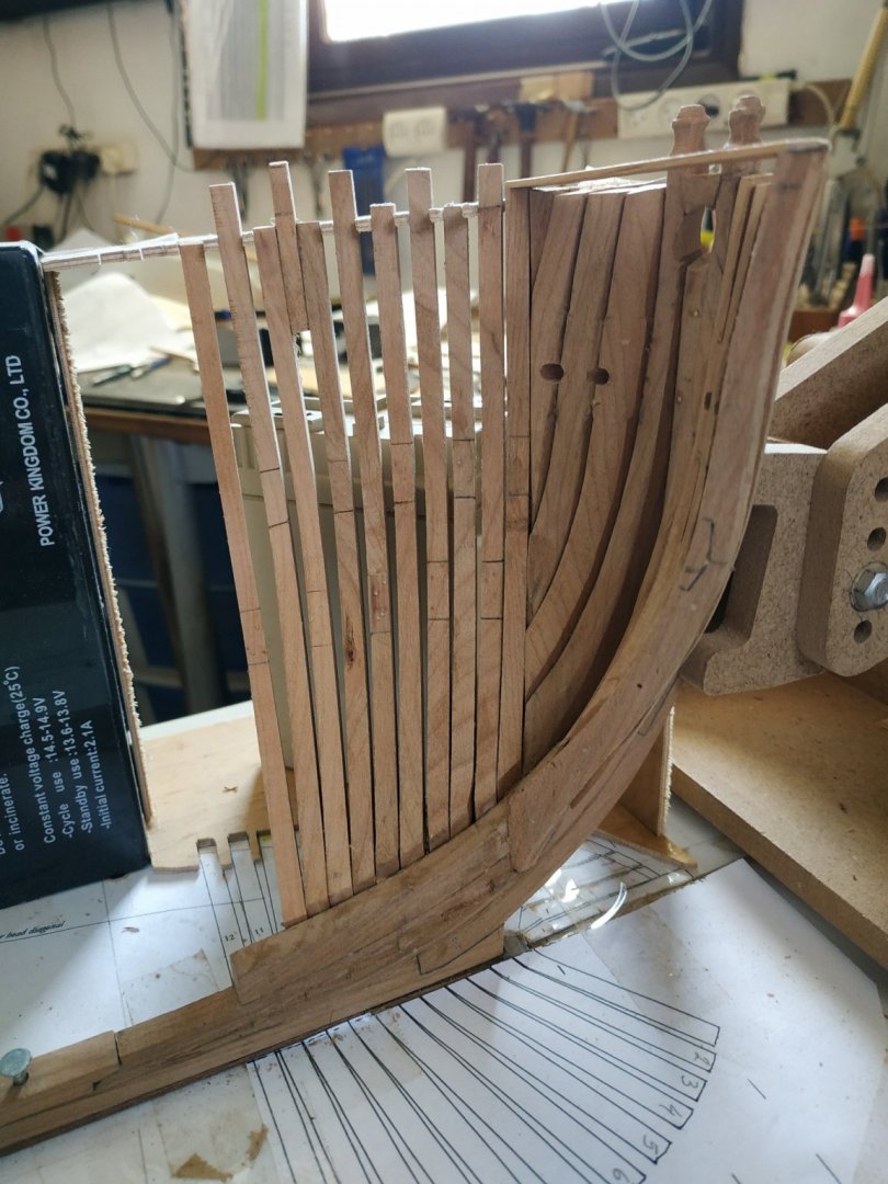
Finishing # 11:
The milling (remove 1mm from each side) and transition (about 10mm) by hand -seems to work OK.
Final port cant #12, 2deg bevel
The jig is not rigid, therefore can be turned over and used on starboard side(with support at 90deg. and a weighted base.The “tooth”between #7and #8 needs removing and the gap for#11 needs widening (for shift).
? Did I mention that I made the cants as pairs, port and starboard, together .
Also reminder to trunnel the “feet” of the cants. One into keel and other into neighbour.
You’ll note that the final effort looks rough, with plenty of work for “fairing”.But this cherry is soft and I hope that the final effect will be acceptable.
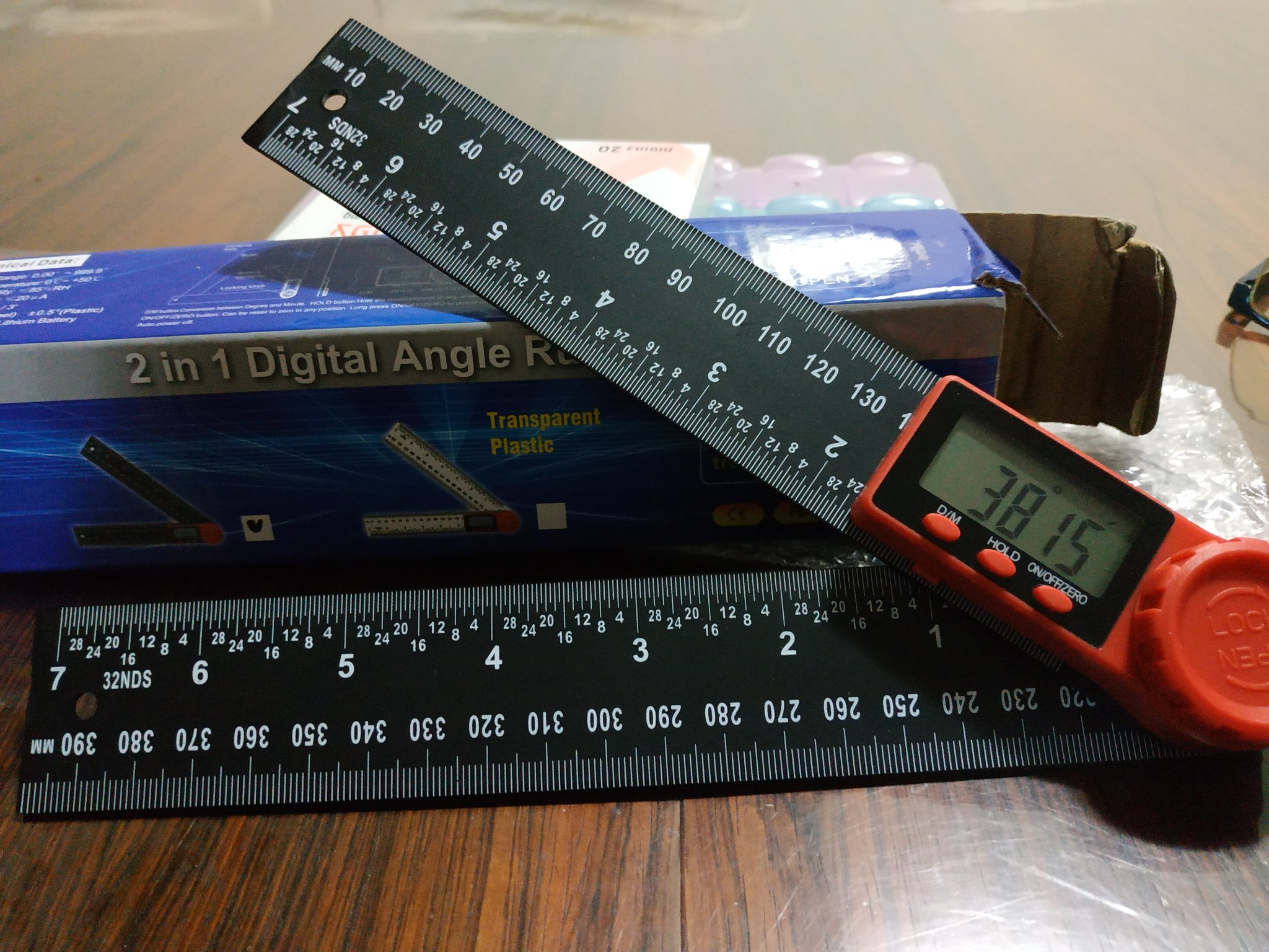
.The last picture is my new digital angle measure. Accurate angles are essential and my old plastic protractor has its problems.


-
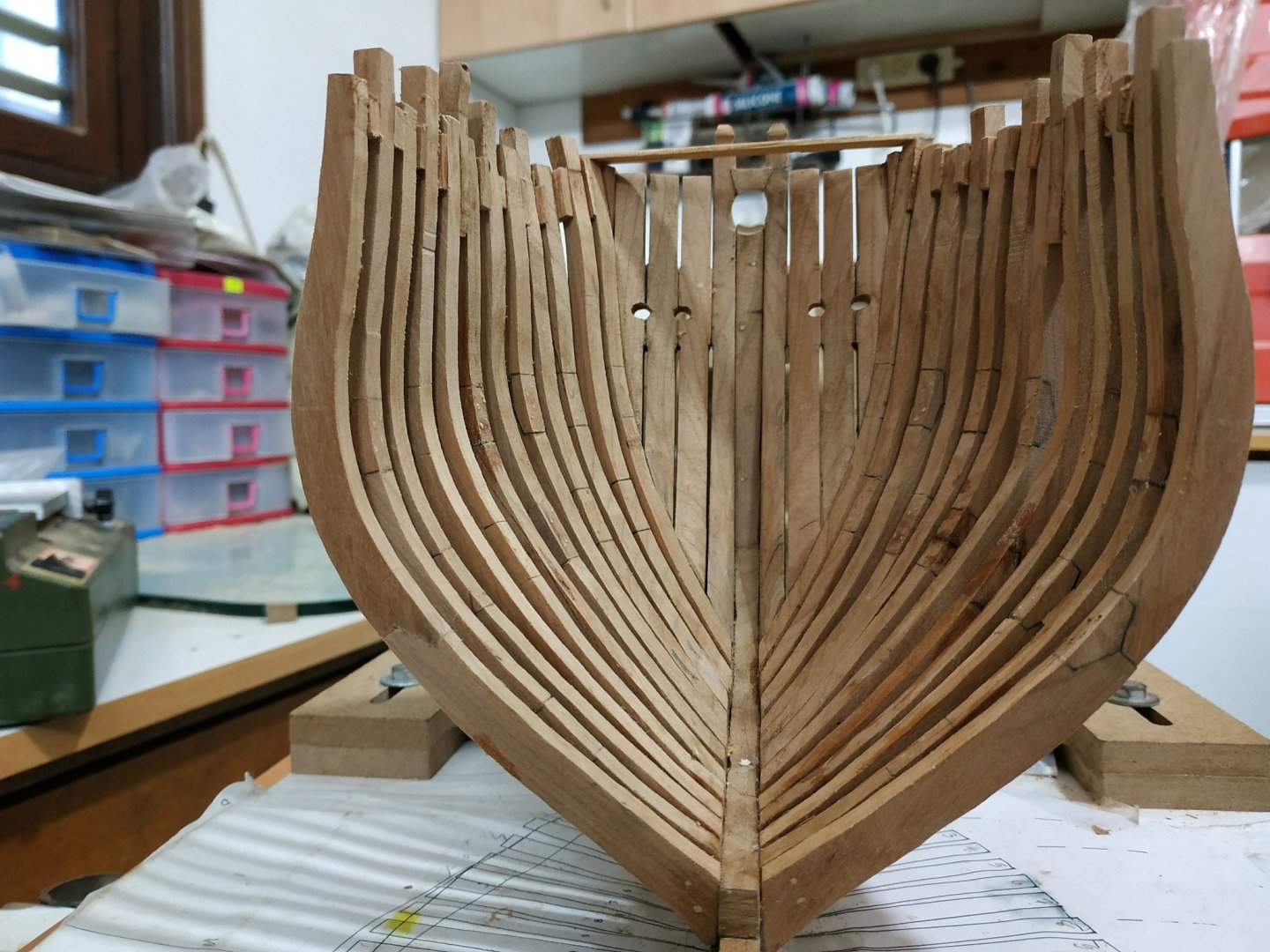
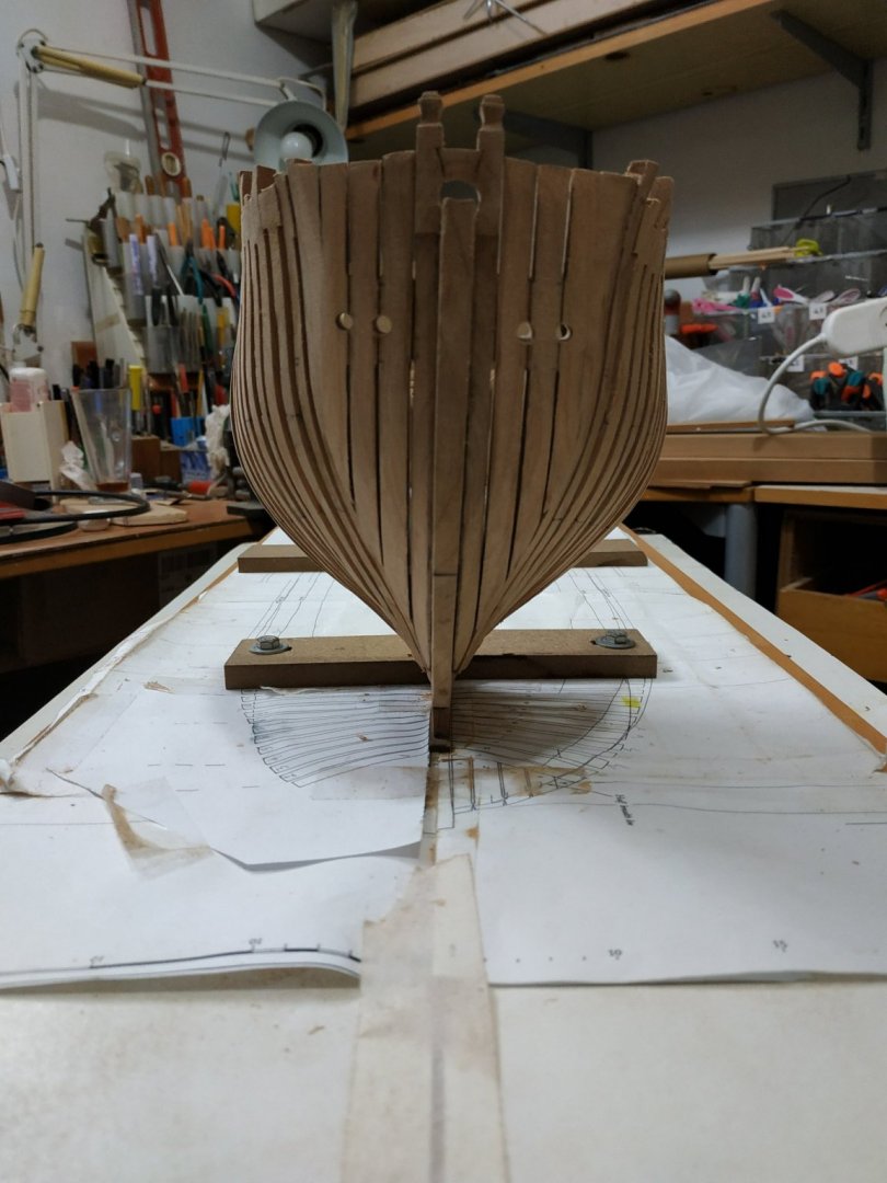
No longer a daily blog.
Of course only having one and a half functioning hands doesn’t improve efficiency. My wife says this isn’t a race-and she is,of course correct,but I like to get things done.
There is an English expression “all fingers and thumbs” meaning clumsiness, but a non-participating thumb is worse!
Can’t help reflecting and comparing the time it takes building a scratch, framed model (and the tools and wood required) against a bulkhead kit. After 20+ models, I thought I could estimate build times. I planned the swan at 12 or 18 months (with or without masting and rigging). I must now double this , and certainly not contemplate a parallel build.
I think I mentioned that I will leave the lower (foot) bevels to later fairing. The first few I did seem to remove too much.
The jig seems to work well.Even though TFFM says the cants 8 to 12 are aligned to the half breadth line,they will also (it seems to me)follow the top timberline -but note this is “inside” the “ends”of the cants as shown on the plans.
Cant #8 has bevel 12deg.
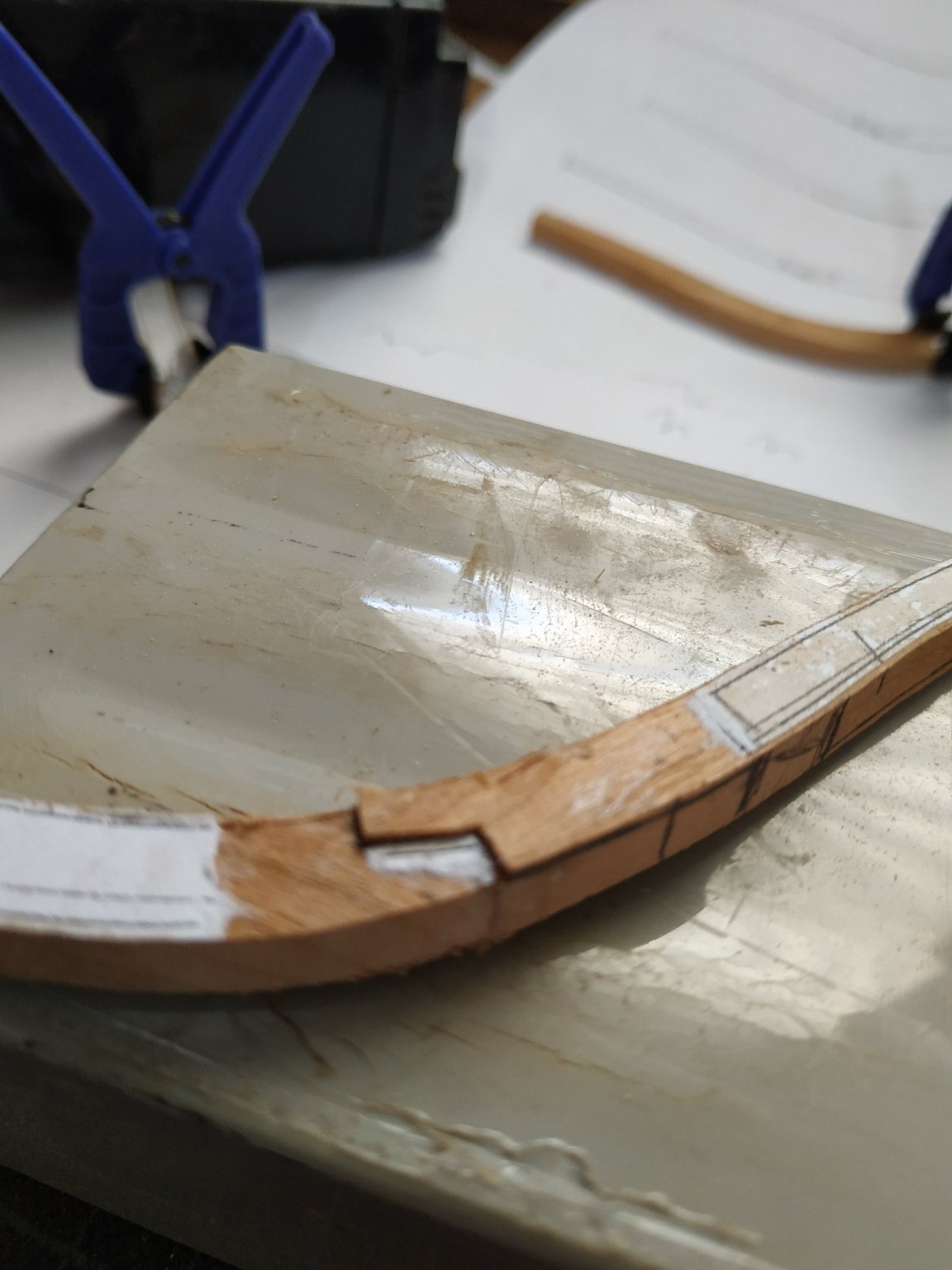
There is a long wedge type piece between #7and #8, extending about 22mm from the top and a max. width of 4.24mm.This is made when #8 is spot glued in place, and when suitably sized, glued to #8 “off-model.
As will be seen from picture, only after this was done, did I notice that it should have extended above the upper timberline as does cants #2,#4,#6.
Another piece to remake.
This “top” is thinner-don’t know as yet how this will be resolved.
Cants #9 (10deg) and #10 (7deg) as before.
Cant #11- TFFM suggests that it is possible to make mortises now rather than later, but accuracy is critical. Given my efforts so far, I don’t think I’m up to it.
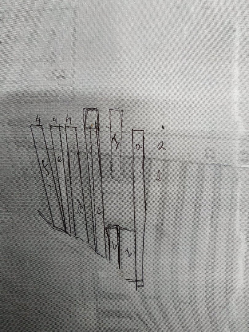
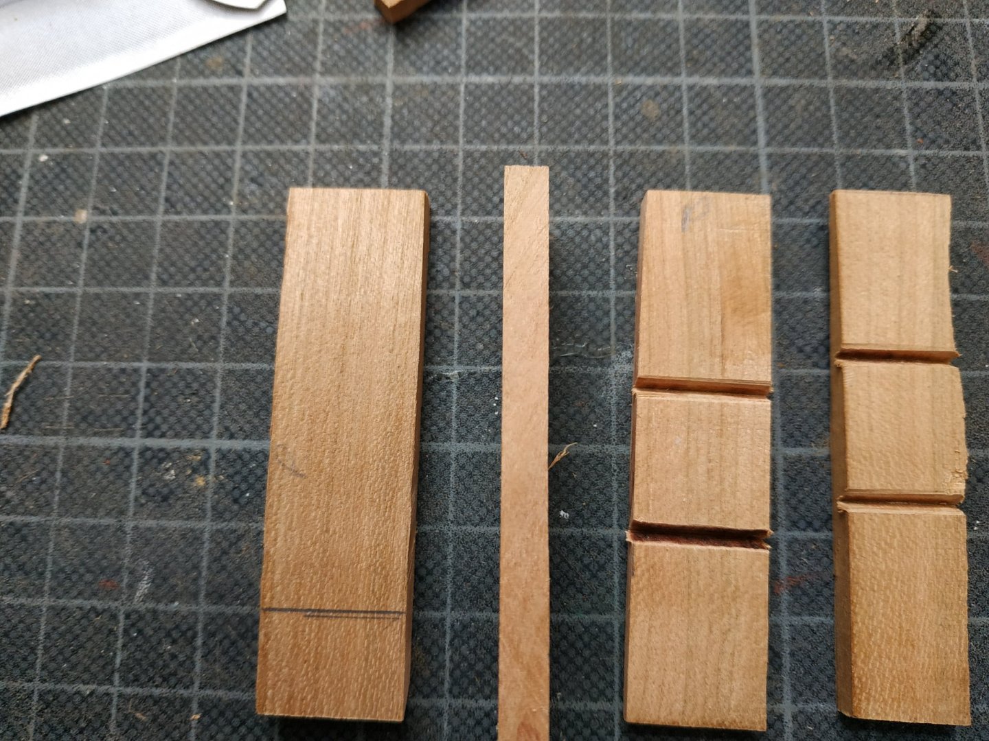
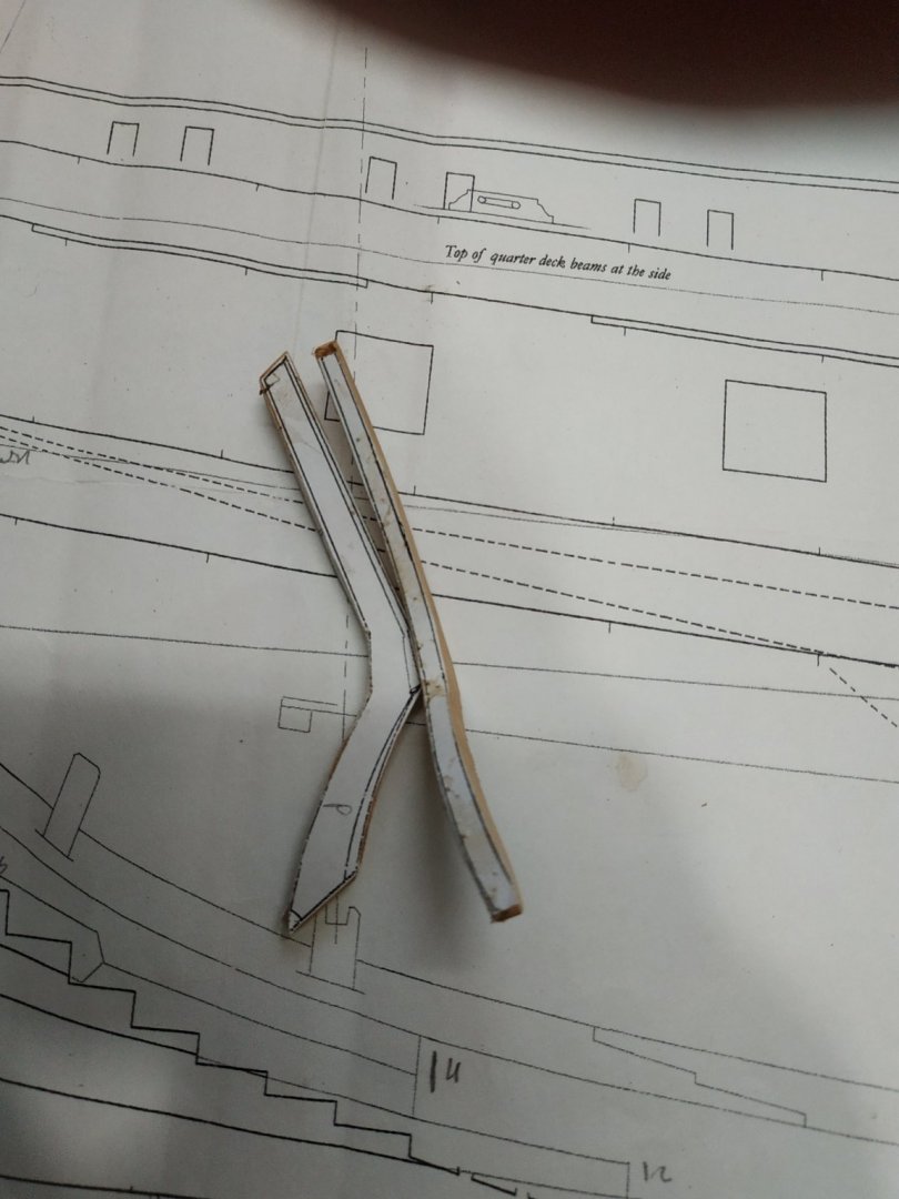
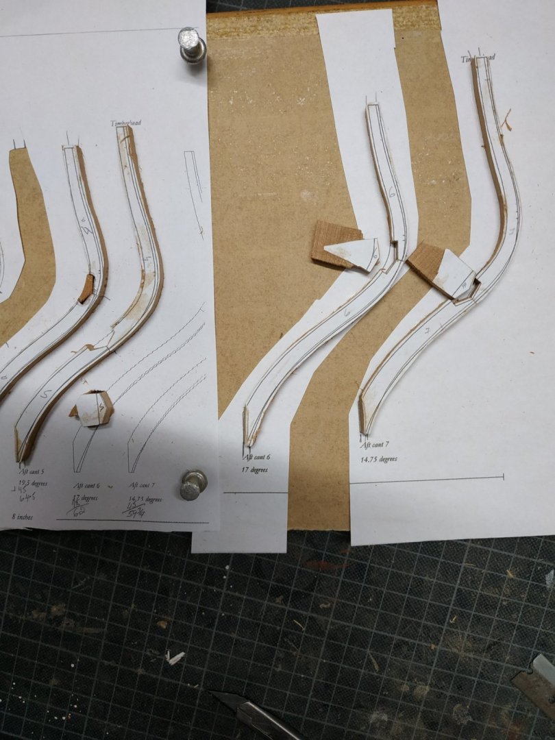
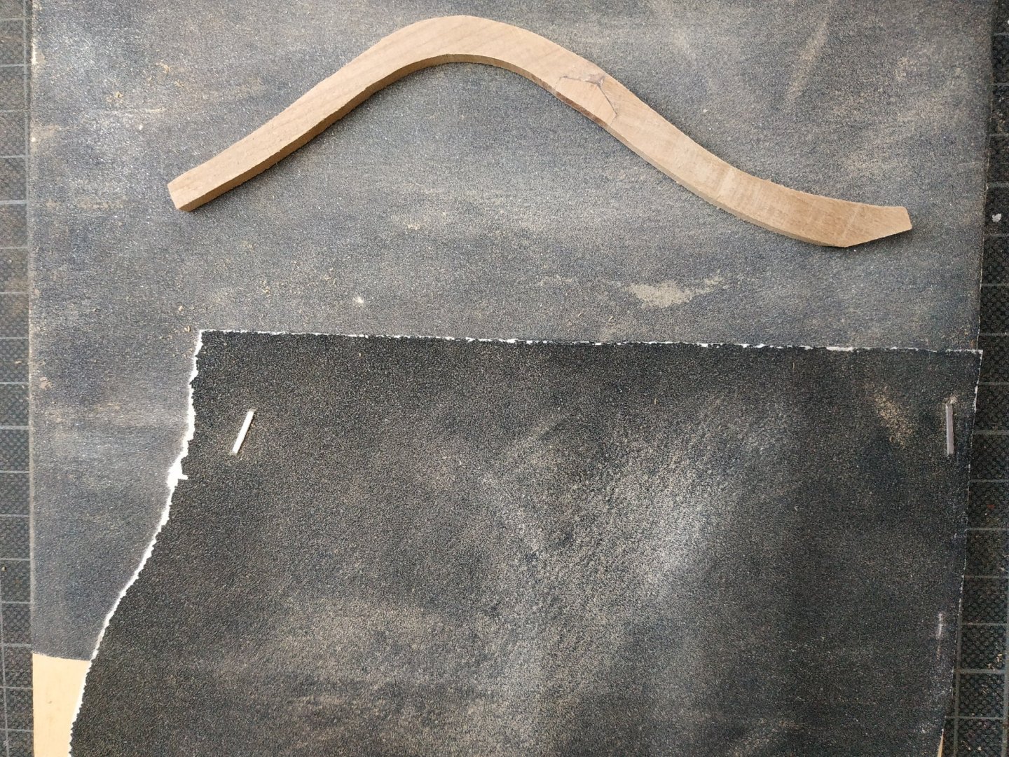
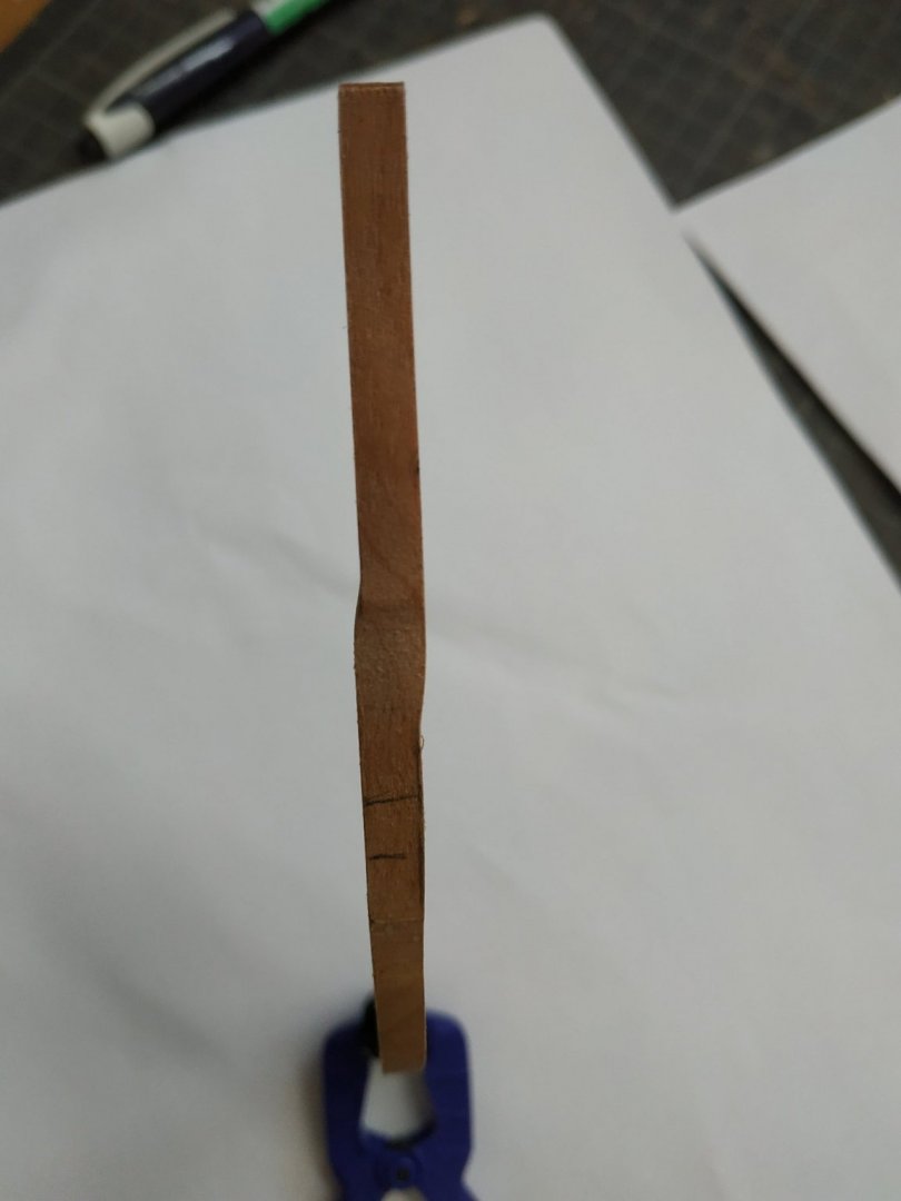
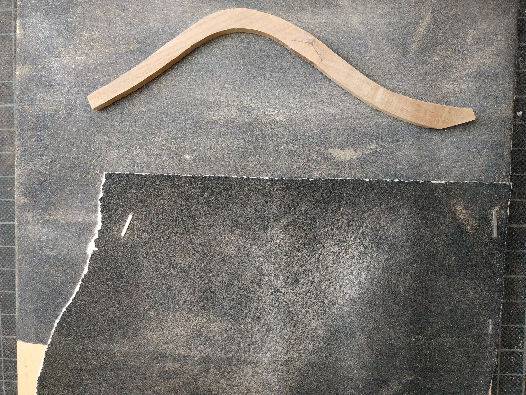
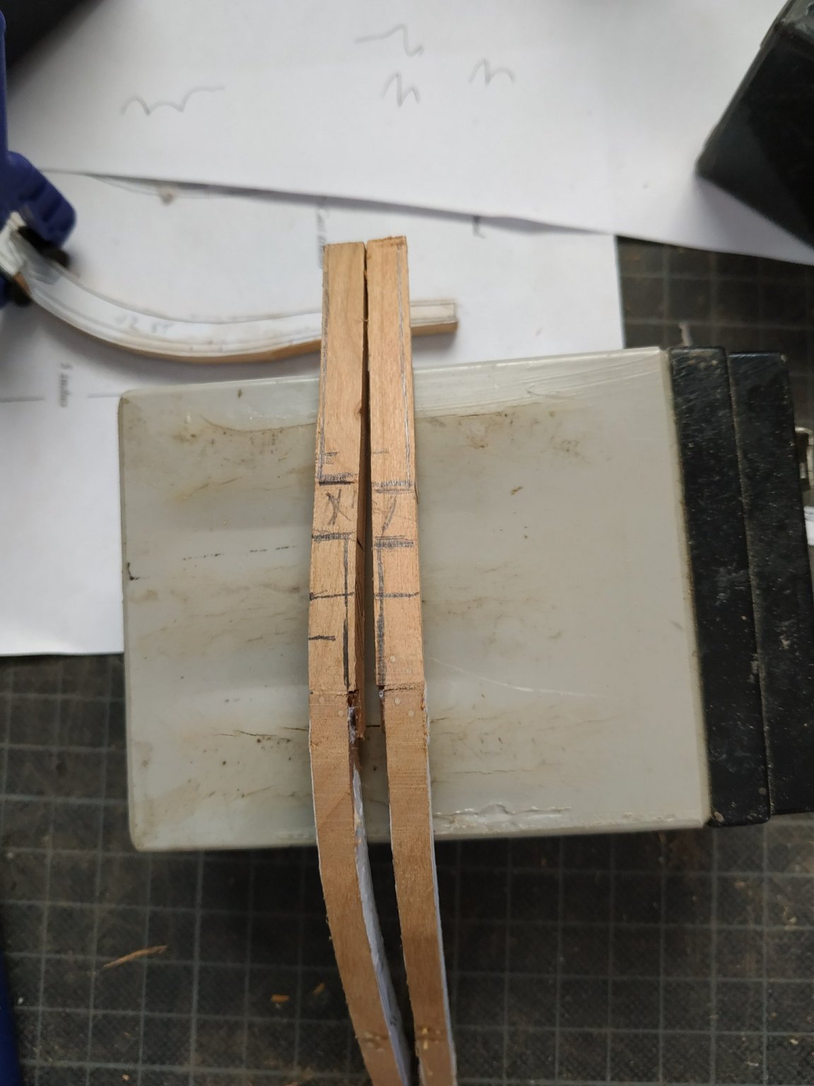
This #11 cant is made from 3 timbers, the upper one contains a “shift” or dogleg. TFFM gives alternative ways of doing this- I opted to what seems the easier “cast” method.
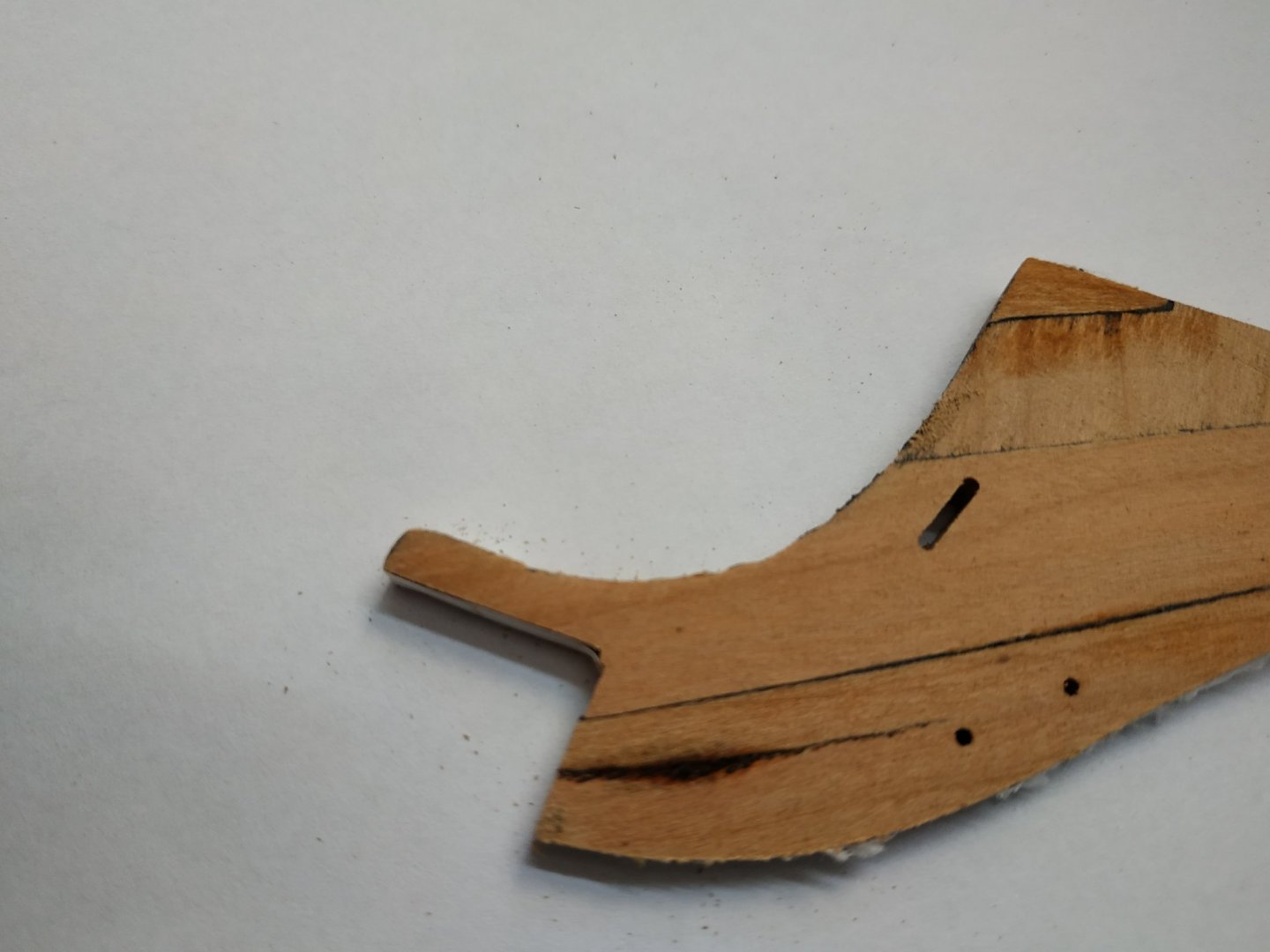
The lower two pieces are 4.77mm wide as before, but the upper widens to 5.83mm. The “extra” is aftwards of the cant.The deviation or transition seems to occur over a 10mm section, finishing BELOW the port. I therefore determined the bend will finish 40mm below top of piece.
To make life easier, I also used a scarf joint.
I marked out the areas to be removed roughly, as my attempt to trace a template from the shear plan was unsuccessful as mine is pretty indistinct.
I intend to mill the straight lengths and finish the bends by hand-tomorrow we will see.


.jpg.0cc6dbf00b485305c0b677a15d6c7c8a.jpg)


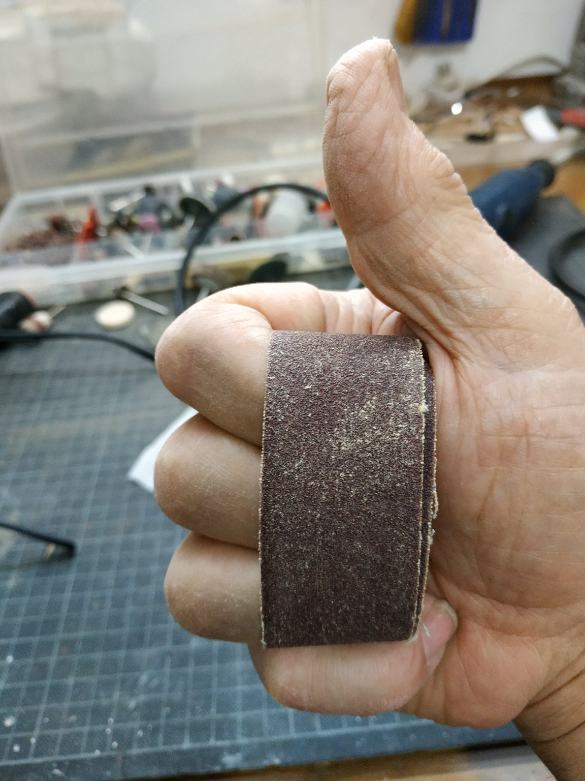


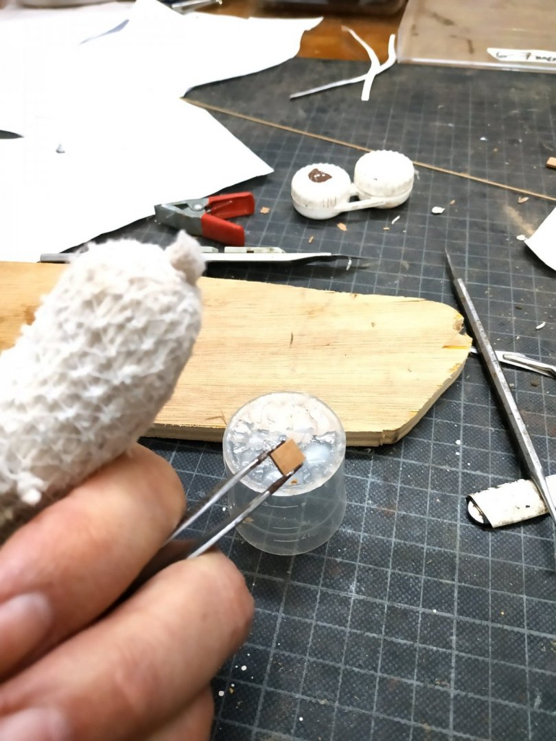
Oscillating Spindle sander
in Modeling tools and Workshop Equipment
Posted
This is a great device, but the upper flange supplied is too small and allows slippage of the large sleeves. A simple fix is shown in picture- a jar top.