


Tony Hunt
-
Posts
476 -
Joined
-
Last visited
Content Type
Profiles
Forums
Gallery
Events
Posts posted by Tony Hunt
-
-
Apologies for the thread drift Richard! Valeriy and I have taken this off-line, so we can now return to the scheduled program - your fine model of the SS Tamahine. It's looking really impressive.
- Keith Black, Valeriy V and mtaylor
-
 3
3
-
On 3/29/2023 at 5:18 PM, Valeriy V said:
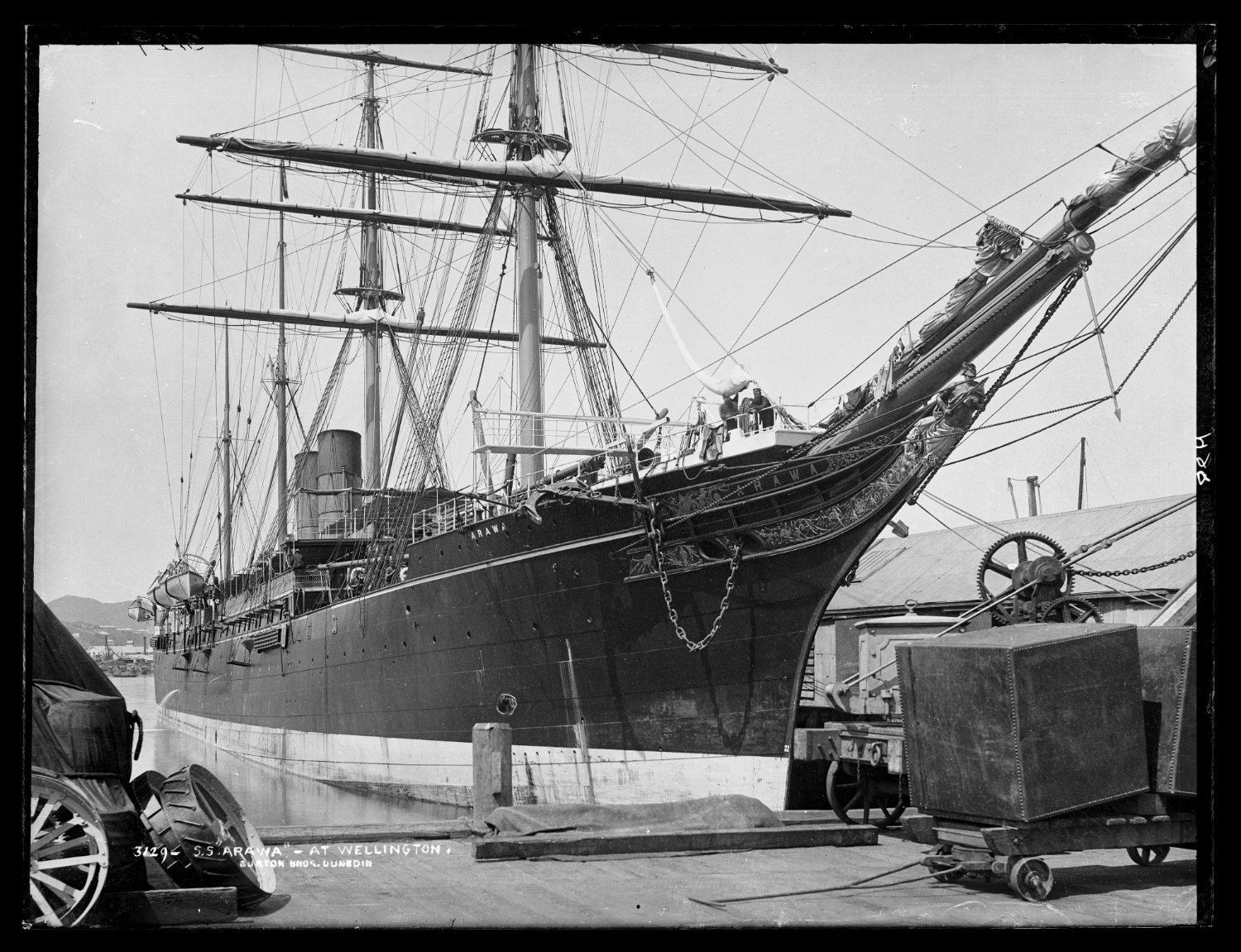
SS ARAWA and his sistership SS TAINUI .
I will be very grateful to you if you learn about the drawings of these ships.
")
Hello Valeriy
SS ARAWA and TAINUI really were magnificent steamers, claimed to be the most beautiful ships in the world at the time.
The plans for these ships are held at the National Maritime Museum in Greenwich. They also have the builders half-model (in a mirrored case) although unfortunately it has suffered some damage, possibly during WW2. It's in storage, not on display. The plans (at 1:48 scale) are quite complete. I obtained copies of them (at considerable cost) for my father, who wanted to build a model of ARAWA. He started but didn't get far before he passed away, aged 90. The only problem with the plans are that the lines plan sheet is badly deteriorated and can't be copied. I got some photos taken and have redrawn them to correct for all the distortions caused by curling paper and parallax error from the photography. Please feel free to PM me if you're interested.
Regards
Tony

.thumb.jpeg.7acc42a8ea4f4861a0096adde2e8b422.jpeg)
-
-
There hasn't ever been a writer who didn't benefit from a good, hard editing! It's been fun following along your voyage of discovery with Glory, great to see the NRJ has recognised the significance of your work.
-
-
-
16 hours ago, Draque said:
Thanks, Håkan.
@Jaager said in an earlier post that on my plans the stations would have been spaced three frames apart and that I could work out my frame dimensions from that. Was this a standard way of drawing plans? If so, how do these dimensions look:
- Distance between stations: 1680mm
- Dividing by 3 gives 560mm for each room+space
- 560mm-305mm(1 foot) = 255mm (almost exactly 10 inches)
So, frames 255mm sided and spaces of 305mm?
So, is this about right (I haven't made the effort to taper the frames as they rise):
That looks pretty good to me.
In general, when a draughtsman is preparing a lines plan from measurements taken off an existing hull (or even a half model), as I suspect is the case for these drawings, then the station spacing is usually (but not always!) arrived at by divided the length of the hull into x number of even spaces (for a ship this size, usually about ten or twelve stations), without reference to the actual frame spacing. The number of stations is usually determined by what is required to properly define the 3-dimensional shape of the hull. The shipwrights would then use the plans to loft out the frames, and usually it was the shipwrights that made the decisions about practical matters such as frame spacing, scantling and planking sizes etc, with reference to the various framing standards put out by classification agencies such as Lloyds. This would often be specified in the building contract, and this may be available as the author of the book about Cuthbert seems to have unearthed a lot of the original business papers. It might be worth contacting him and asking. A lot of these old Royal Navy documents are still around in dusty old archives somewhere!
-
Fighting warships were usually pretty close-framed, but for a lot of commercial vessels the framing was often "room and space", where the gap between the frames more-or-less matches the width of the frames. I'm guessing RENARD and her sisters would be more likely to be framed room and space, even though they were built for the RN they weren't really fighting ships intended for action in naval battles. So in the case above, if the frames are 10 inches moulded the space between would also be 10 inches.
-
You're welcome, I enjoy a bit of ship research! I think you'd have to go in to the library at the Australian National Maritime Museum to see the journal, it doesn't appear to be digitised. They're very helpful people, I've been there often.
In an interesting twist, it turns out ETHEL wasn't built by Cuthbert, but by another well-known Sydney shipbuilder, Daniel Sheehy:
The schooner Ethel, built by Mr Sheehy at Woolloomooloo Bay, has been purchased by the Imperial Government, and will be armed and fitted as a gunboat, for the purpose of cruising among the islands.The Sydney Morning Herald, Fri 16 Aug 1872, Page 4, SHIPS' MAILS.
From The Sydney Morning Herald, Fri 19 Apr 1872, Page 4, ROYAL MAIL NOTICE, it appears she was launched in April 1872.
There is a nice picture of Sheehy's yard on Flickr, with the steam schooner Llewellyn ready to be launched, in 1874. The background action is interesting!

-
-
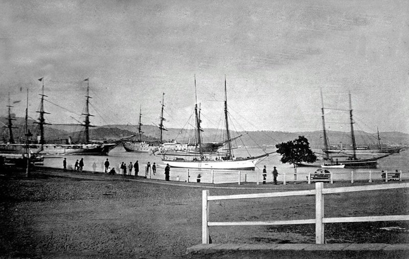
Although these photos lack detail they are nicely broadside-on and far enough away that parallax error is trivial, so they will be good for a number of purposes for your model, such as scaling the lengths and angles of the rig.
-
Hi Michael
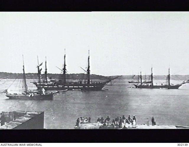
I wouldn't buy Bastock's book just for the photos. The original from the Harry O'May collection are available on-line at the Maritime Museum of Tasmania (see post above), while the picture of the CONFLICT from Bastock's collection is available on-line at the Australian War Memorial https://www.awm.gov.au/collection/C237572, a low-res copy is below with CONFLICT (in Sydney Harbour c1875) on the left.
I wish I had your skills in CAD drawing. I've been trying to teach myself using TurboCAD but it's proving to be a losing battle!
-
-
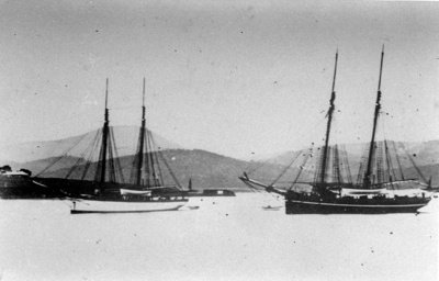
Here are ALACRITY and BEAGLE, taken at anchor in Hobart.
-
Hi Michael
I love your project! As a Sydneysider I too have a strong interest in the ships that were built here or sailed from here, and RENARD (or any of the blackbirding flotilla schooners) is a great choice. I didn't know the plans were available, nice work finding them.
The plans themselves are interesting. They show a hull with a slight clipper bow, so presumably they are the plans for ALACRITY, originally ETHEL, which it appears was purchased by the Navy rather than built for them specifically like the other four schooners. I wonder who drew these plans? I assume ETHEL was designed in Sydney by Cuthbert or one of his colleagues*, so perhaps these plans ended up with the Navy (and thus in the collection at the NMM) as part of the process for reviewing the design prior to ordering the next four schooners in the series?
There are poor photos of ALACRITY, BEAGLE and CONFLICT at anchor in Sydney Harbour on pages 58 and 59 of John Bastock's book Ships on the Australia Station. It might be possible to track down the originals, the images of ALACRITY and BEAGLE are credited to Mr H. O'May (presumably the Tasmanian maritime historian Harry O'May https://adb.anu.edu.au/biography/omay-henry-harry-11304) while the picture of CONFLICT came from Bastock's (https://www.navy.gov.au/biography/mr-john-bastock) own collection. Both these gentlemen passed away long ago and I don't know where these collections ended up, but both were reputable historians so I expect they would have ended up in a public collection somewhere.
Re the frame heads question, the usual practice was to end the frames below the deck and put stanchions between the frame to carry the bulwark planking. This reduced the likelihood of fresh water and thus rot getting into the frames.
Anyway, great project and I look forward to seeing it progress!
Cheers
Tony
*Perhaps not - it seems a bit unclear who built ETHEL.
-
It's looking really good, Håkan. Happy New Year!
- Keith Black, Wintergreen, mtaylor and 1 other
-
4
-
I think a lot of us would be happy to achieve results that good at considerably larger scales.
- FriedClams, Bedford, mtaylor and 2 others
-
5
-
While I fiddle around lofting frames, here is a little about the process I use to take the lines off these vessels, which I hope is of interest. I've done this for about a dozen of these luggers (about half of all the ones that survive) and just as well really, as at least five of these have since been destroyed and several more are "at risk". It's a tough world for 100-year-old wooden boats that need very expensive restoration and maintenance, and aren't all that practical as private pleasure craft when you're finished.
I should preface what follows by pointing out that there are lots of ways to do this and this is just the way I do it. I haven’t tried any of the other ways so I can’t really say whether they are better or worse; but having used this method quite a few times now I’m at least sure that it works reasonably well for vessels with a straight keel. The method has evolved a bit over the years in the light of experience and I’ve now got it down to a pretty slick process – I can lift a good set of measurements off a ~50 foot hull in a single day. Of course, modern computerised laser surveying gear (as used by yacht raters and the like) makes manual methods like this redundant, but I can’t afford the price and in any case it seems to take a lot of the fun out of the whole thing.
The boat has to be out of the water, of course. I’ve measured luggers on slipways (marine railway type); on tidal slips; on the hardstand (after being lifted out by travel lift); lying abandoned on a mudbank; and even sitting on a cradle in a museum gallery. The method works OK for all of them, but as a rule the more level and upright the boat is sitting, the easier it will be. The availability of things like a workbench, a covered shelter (to keep your notes dry when it’s raining!), bathroom facilities and a not-too-distant source of cold drinks, hot coffee and sticky pastries also help, although they’re not essential. When measuring pearling luggers a mixed flock of sandflies and mosquitoes are usually present so insect repellent is essential, as is sunblock.
Luggers are usually found in remote parts of Australia so nearly all the tools I use can be carried as checked luggage on an airline. The main ones are clamps (I mostly use quick grips, they’re fantastic); a selection of tapes and rulers (including a long, non-stretch tape on a reel); a selection of spirit levels, plumb bobs and bricklayers stringlines; a carpenters square; a selection of marking devices including chalk, tape, marker pens and small nails; a clipboard and notebook; and of course a camera. When I arrive I find a hardware store and buy three long, straight pine battens – 3 metres x 40mm x 15mm works fine for boats the size I work on; larger boats might require longer battens. I also need to borrow a reasonably large ladder, fortunately most boatyards can supply these if you ask nicely. Using a tape and the marker pens I turn the battens into three large rulers, marked in feet and inches.
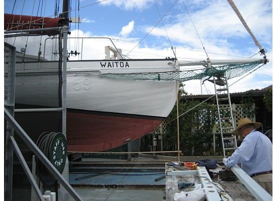
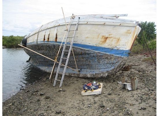
The first step is to establish a zero datum, which is the point on the boat to which all subsequent measurements will be able to be related. I make this at a recognisable point on the top of the stem (usually either the forward or aft edge of the bowsprit gammoning strap where it crosses the stemhead) and mark this with something like a clamp, which should remain in place for the duration of the survey. I next drop a plumbline down the stem from the zero datum, to establish whether the boat is sitting level and to carry a reference line down to the level of the keel. If possible I establish another datum point at this level – a big block of wood with a nail in it seems to work well.
The picture below illustrates the idea. The zero datum for this survey of the 1904 Thursday Island lugger WAITOA is marked by a clamp (just visible) at the top of the aft edge of the bowsprit gammoning strap.
Measuring from one or both of these datum points, I then run a long tape the length of the boat and mark off the station intervals. As a rule of thumb, divide the overall length of the hull into ten equal parts, this gives the approximate station spacing. On pearling luggers, which are generally a bit over 50 feet long, I use station intervals of six feet. If the hull has strong curvature at any point (such as the stern quarters) it may pay to put some extra stations in to better define the shape of the hull in that area – this is a matter for judgement and of course experience helps in this regard. If there is an obstacle in the way of a station (such as the arms of a slipway cradle) it doesn’t matter, the station can be moved a foot or two without affecting the outcome . I try to record the positions and dimensions of visible hull features (things like deckhouses, chainplates and the like) that can be seen in photographs and used to scale dimensions on them. I use feet, inches and eighths (because pearling luggers were built in the era of imperial measures) and record them using the usual feet-inches-eighths shorthand used by shipwrights, so 20-8-5 is 20 feet, eight and five-eighths inches.
Once the station intervals have been marked (chalk or tape works well) the bulk of the work begins – establishing the cross-sectional shape of the hull at each station. I do this by using the three batten rulers and clamps to build a triangular frame of known dimensions against the hull at the station, and then measure offsets from it to the hull. The frame should be a right-angled triangle and follow the shape of the hull reasonably closely – measuring short offsets is easiest and offsets more than three feet long can get very tricky. If the boat is level and upright the two sides of the triangle that meet at the right angle should be set horizontal and vertical respectively, using spirit level, plumbline and carpenters square. The station can be established perpendicular to the waterline, a stringline or the line of the keel. Of these, the waterline is preferable, firstly because most NAs these days seem to follow the convention of drawing cross sections set at right angles to the waterline, and secondly because the keel isn’t always dead straight (due to hogging, for example). If the boat is lying on its side I set up the stations at right angles to the side face of the keel. This introduces an unwanted source of error and is far from ideal, but sometimes you don’t have any choice. The pictures below illustrate what I mean; they show the abandoned hulk of VIKING, looking very forlorn.
The next picture is a detail of the measuring frame made from the batten rulers, showing the right angle where the vertical and horizontal battens meet.
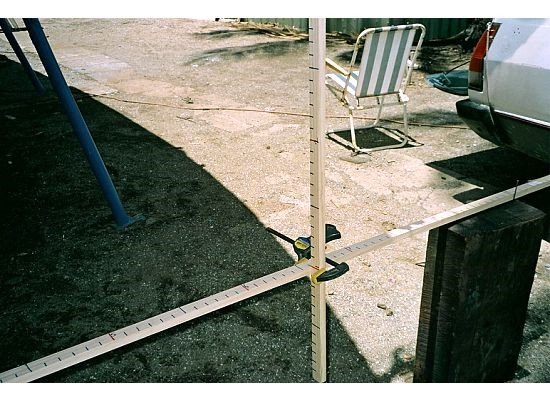
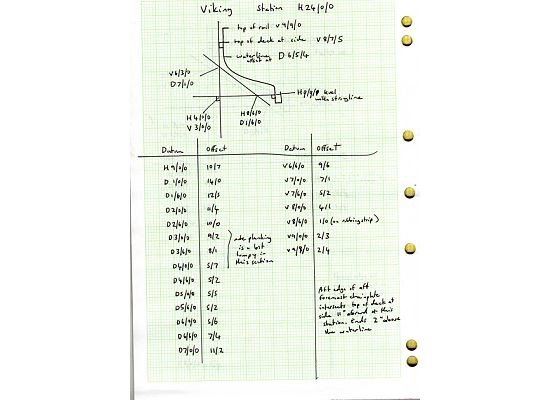
The measuring triangle can be accurately defined by recording the points where the battens intersect. I do this by referring to the battens as the vertical, horizontal and diagonal (V, H and D respectively) and so an intersection point of the triangle might be recorded as V 2-6-0, D 8-5-4. In other words, the vertical and diagonal battens intersect at the two foot six inches mark on the vertical batten and the eight feet five-and-a-half inches mark on the diagonal batten. I also record the key points where the triangle intersects the hull. I draw a sketch to record all this, like the one below:
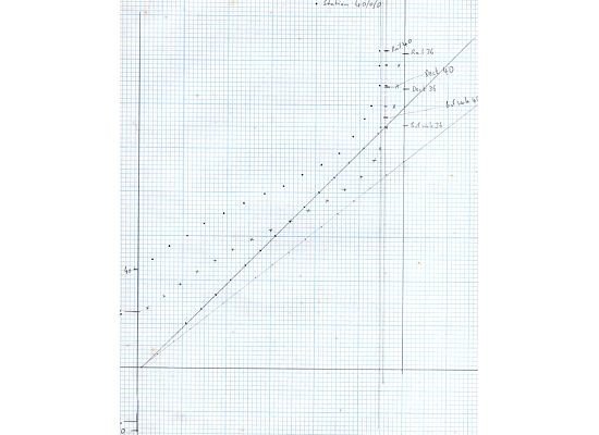
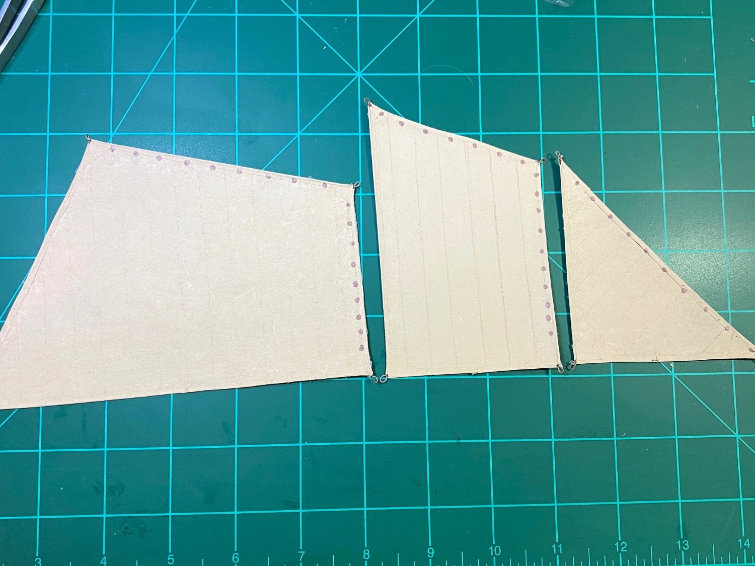
Once you have all this data, the laborious task of drawing it all up into a conventional set of boat plans can begin. I start by plotting out each of the sectional shapes, first drawing up the triangle, then plotting out all the offsets and then “joining the dots”. As the example below shows, the method gives very clear and fair curves.
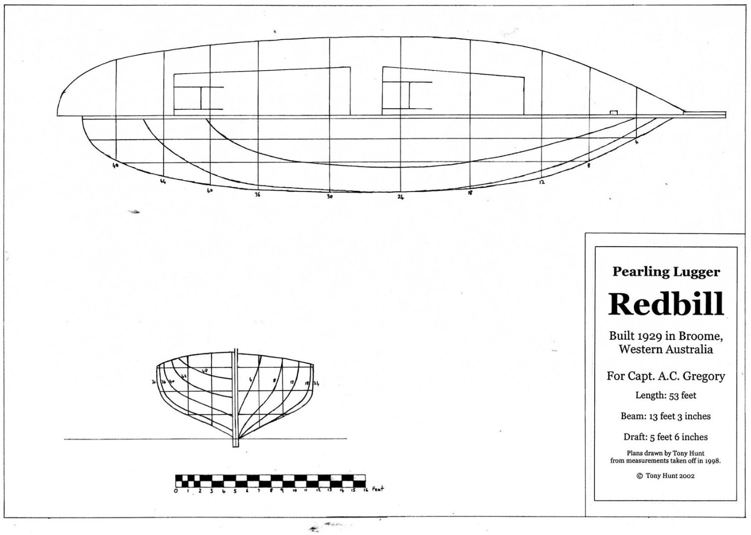
Once you have these shapes, the usual methods are followed to draw the hull, fairing the waterlines, buttock lines and diagonals etc. There are numerous textbooks describing this process in detail, so I won’t repeat it all here. Suffice to say that the quality of the result from this point will reflect your skills as a draughtsman – I hope yours are better than mine! The end result will (hopefully!) look something like the drawing below, in this case showing the 1929 Broome lugger REDBILL.
 Of course, lots more measurements of details , deck layouts, rig etc can be added, and historical pictures are useful so you can see what has been modified over the years.
- French Mr Bean, ccoyle, wefalck and 3 others
-
6
-
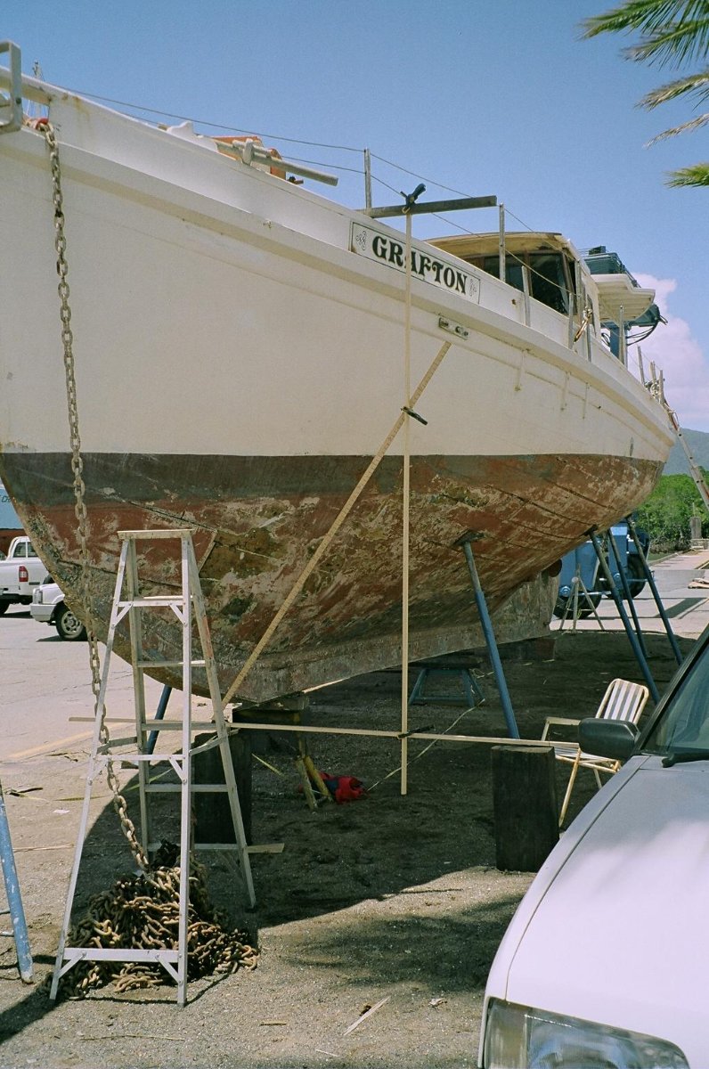
After much prevaricating about what to build, I've decided to start with an obvious choice and build a Thursday Island pearling lugger. It's an obvious choice because I've spent so much time (decades!) researching these vessels.
The one I've chosen is GRAFTON, a classic example of the type, built during the heyday of the industry in 1907 at Thursday Island (the main settlement in the islands of the Torres Strait, between Australia and New Guinea) by a Japanese shipwright, Tsurumatsu Shiosaki. The Japanese had started entering the pearling industry in the Torres Strait in the 1890s and quickly came to dominate it, both as divers and as shipbuilders, mainly due to their willingness to work very hard and for lower wages than Australian shipwrights.
GRAFTON had a long life, working as part of the Wyben Pearling Co. fleet (owned by Burns Philp & Co. Ltd) until WW2, when she was impressed into military service along with the rest of the pearling fleet, in 1942. She survived the war and was returned to Burns Philp & Co. in 1946, resuming pearling until the late 1960s. She then passed through various private owners, steadily deteriorating and on one occasion capsizing and sinking. She was raised, but never sailed again, and was eventually abandoned on a mudbank in Port Douglas, where the port authorities eventually removed her and broke her up in March 2019.
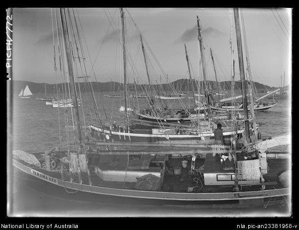
GRAFTON (seen here behind the lugger PARAMA in the foreground) in her heyday, 1930, at Thursday Island.
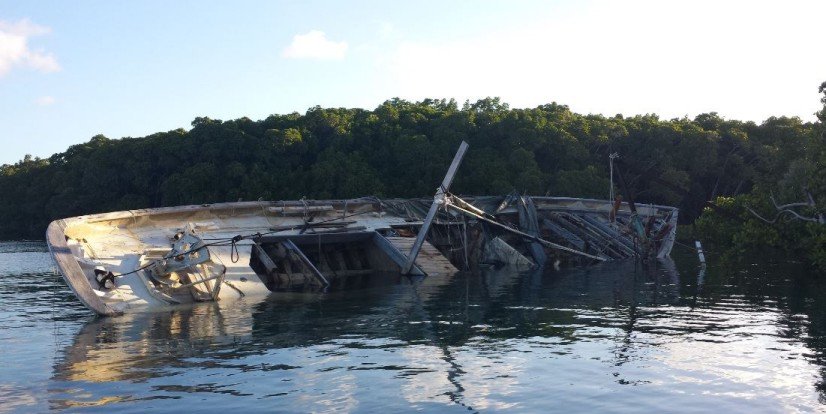
GRAFTON abandoned on a mudbank at Port Douglas, Queensland, shortly before she was broken up in 2019.
As part of my ongoing research into these luggers, in 2007 I took the opportunity to take the lines off her while she was up on the hardstand at Cairns, getting a bit of maintenance. Her owner at the time loved her dearly, but lacked the resources to do the full restoration that a 100-year old really lugger needed after a long and hard life. In two days I filled a notebook with measurements, and a while later my research colleague Michael Gregg, curator of maritime history at the Western Australian Maritime Museum, arranged for Naval Architect Bill Leonard to use these measurements to produce a beautifully executed drawing of her.
 Taking offsets
Taking offsets at Cairns in 2007.
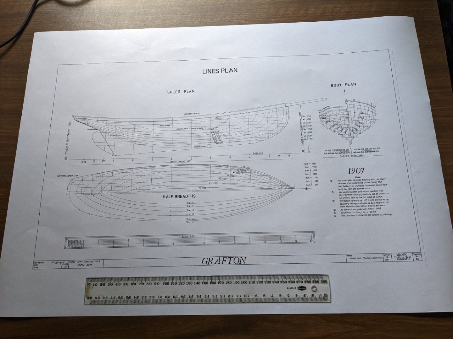
Bill Leonard's draught of GRAFTON produced from my measurements.
At the moment I'm lofting frames and getting myself organised to get started. I've decide on a scale of 1/50, which gives a hull a bit over a foot long. The plans were drawn (in metric) at 1/20, so it was simple to print them at 40% to give the desired size, and 1/50 is close enough to 1/48 to make it easy to scale all the myriad measurements I took in feet and inches for all the details of the layout and rig.
Enough to begin with, I think. More to follow!
- FlyingFish, GrandpaPhil, mtaylor and 4 others
-
7
-
I can see that I really must buy myself a milling machine... 😃
-
"It's not perfect, but I'm content with the finished product."
So you should be! It looks really good.
-
On 8/28/2022 at 5:23 AM, Roger Pellett said:
Had time today to look at my David Mac Gregor books for info on Thermopylae; results:
Merchant Sailing Ships 1850- 1875 Two references to Thermopylae but no drawings. Says that builders drawing (hull lines) does exist.
Fast Sailing Ships- Their Design and Construction 1775-1875
Includes: Hull Lines Drawing , Reconstructed Deck layout, Sail Plan
The Book also includes several pages of text about the ship
I believe that the people who manage the SS Great Britain in Bristol own David MacGregor’s Drawings and sell copies.
Roger
Roger, you're quite correct, I've bought plans from them and they were very helpful and reasonably priced.
The full list of the collection can be seen at https://www.ssgreatbritain.org/wp-content/uploads/2021/05/david-macgregor-ship-plans-collection-july-2013.pdf there is a large amount of material on the clipper ship Thermopylae.
- mtaylor, Keith Black and Scottish Guy
-
3
-
On 9/7/2022 at 7:04 AM, My Fathers Son said:
I am going to have to hope these print a bit clearer as in A4, the Scale in the corner condenses a foot down to 50mm. A2 will not be full size hopefully reduce the scope for error when adapting the scale.
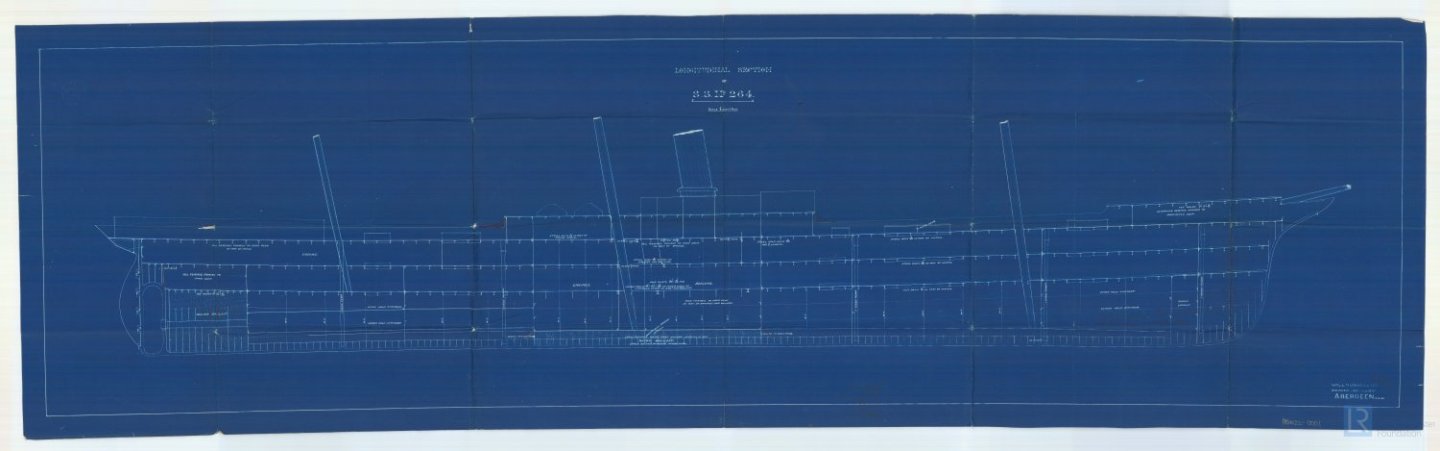
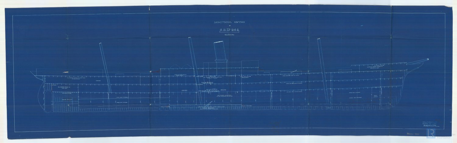
That link you put in Bruce is an incredible resource. It would appear that in September 1890, plans to convert her to a sail assisted steamer were drawn up,
I dont think i want to go down this route, there are a couple of deck plans that should prove usefull and plenty of reading. Thank you Bruce, this will keep me busy for a while.
Simon
Hello Simon
All the material on that link (which is fabulous, by the way) is for a different ship entirely, the screw steamship SS Thermopylae, also built by Hall Russell in Aberdeen, in 1891. It was a much larger ship (350 feet long) so I'm afraid it won't help you with your model.
Cheers
Tony
- Keith Black, My Fathers Son, mtaylor and 1 other
-
4
-
.jpeg.1b566d8ae5417a2302f3e9a68e5ab075.jpeg)


Fullerton by Al Litchfield - RESTORATION - four-masted barkentine
in - Build logs for subjects built 1901 - Present Day
Posted
It's a very nice model, well worth the time and effort for a good restoration. A very interesting and unusual subject, and it looks to have been well made. I agree that care is needed to avoid over-restoration.
The deck is most unusual. Is it really paint? It looks like some kind of adhesive film that has a deck printed on the upper surface, that has now cracked and delaminated from the brass underdeck. I agree with Roger that it might be best to do as little as possible other than preserve what is left.