


Kevin-the-lubber
-
Posts
1,215 -
Joined
-
Last visited
Content Type
Profiles
Forums
Gallery
Events
Everything posted by Kevin-the-lubber
-
 In what sense, Bill? Taper-wise?
 -
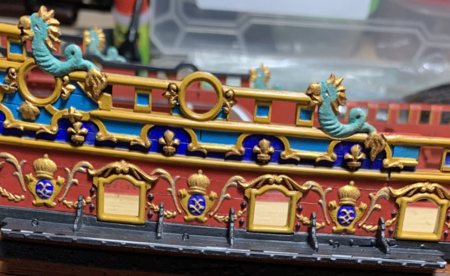
But it’s not, really, is it Marc. I think all of us are as one in recognising you have a talent that many of us don’t, and while we may attempt the same, there’s no guarantee that spending more time will yield the same result. You are an artist, it’s as simple as that, and it is always - absolutely always - a pleasure to watch an artist at work. As mentioned elsewhere, watching yours and John Ott’s work on this model is like doing the very best arts degree going. People pay to learn this stuff! Anyway, enough of the praise 😀, down to business. That is such a well observed change, the remodelled figure now flows with the rest of the decor in that area and just looks right. I’d love to see a side-on view as well, when you have time and inclination.
- 2,667 replies
-
- 3
-

-

-
- heller
- soleil royal
- (and 9 more)
-
Hi Marc There are things I want to become better at or able to do per se, which I'm trying out at present on the Victory, that will have a bearing on the SR. The main one of these is creating a faithful digital replica of the kit hull, as I think that is key to making complex replacement parts, such as my Vic stern, fit well on a kit hull in a repeatable way. Currently I'm wrestling with a rather poor quality 3D scan of the Victory hull, but if I don't crack this in the next few days I may go back to an earlier idea, plotting points manually using a plotting jig and transcribing these into the software. I know I could just fudge the stern fit as a one-off and that'll be the fall-back; equally, I could make a new hull using line drawings, but from there I might as well go the whole hog of scratch building, which I don't really want to do. I think I'd rather just build the kit out of the box in that case, because it is, after all (like the Vic) a beautiful kit in it's own right. Anyway, I'll plug away for a while longer before resorting to the model-makers equivalent of a manchester screwdriver. I read John Ott's wonderful opening essay on the model being a replica of Tanneron and it registered that the height of the kit stern plate is exaggerated, as per artistic licence of the day (and the draught is all wrong). I think a proportionate stern plate would logically lead to a greater tumblehome angle and probably also require remodelled upper bulwarks, which don't look too hard to do.... and quarter galleries, which do look hard.... so by the time all is said and done, a new stern. Familiar territory, hence wanting to have my 'workflow' and methods clear well in advance. I need to go back through your log as a partner piece, as between you and John, you present a lot of food for thought around the stern.
-
Wisborough Green eh.... luckily for you, beyond telescope distance 🙂. Haywards Heath here.
-
It'd be great if the made the mesh freely available, I'd snap that up in a heartbeat. Ironically, I used to stay with friends near Dundee a lot up until 20 years back, but had no interest in ships or model-making back then.
-
Nicely recovered Bill. Busy looking deck, isn't it.
-
Ian, left field, pragmatist thought - add a little hidden motor and prop at the stern, just to overcome the limitations of scale? Probably not what you want to do, but to a very great extent I think you've already achieved a lot and shown what's possible (and less possible) with oar power alone.
- 536 replies
-
- 2
-
-
- Quadrireme
- radio
- (and 1 more)
-
A brief note, that Heller have now made the new assembly instruction booklets for both the Victory and Soleil Royale available for free download. You can get them here; https://www.heller.fr/en/80897-hms-victory-1000808970 https://www.heller.fr/en/80899-soleil-royal-1000808990 I've managed to resist the first wave of temptation to start working on this model. It looks to me like this kit is especially suited to a bit of 3D replacement and printing; a flat stern plate, virtually flat upper bulwarks, coupled with a wealth of information and ideas in other people's logs.
-
A brief note before I forget, that Heller have now made the new assembly instruction booklets for both the Victory and Soleil Royale available for free download. You can get them here; https://www.heller.fr/en/80897-hms-victory-1000808970 https://www.heller.fr/en/80899-soleil-royal-1000808990 Otherwise, I've almost finished re-creating all the blocks, hearts, deadeyes etc based on McKay for printing in resin. I know this has already been done by a few others but I found it an interesting exercise during which I learned a few things about block design, as well as the sheer variety used on the ship - about 100 different models, taking in the various designs and size variants. While I've modelled them all true to McKay, like others I will convert all of this into a smaller set of practical models, as some of the 'true' sizes are too small for use at 1:100. In any case it's been a useful way of getting my head back into the Victory, as I plan to focus on this again for a while.
-
3d printing process
Kevin-the-lubber replied to henrythestaffy's topic in 3D-Printing and Laser-Cutting.
Ron, that bowed edge is the same issue that I had when printing cabins for my Cutty sark. Similar objects I.e. straight edges. The issue occurs almost regardless of object size - it was even happening on 1} square hatch covers, which was quite frustrating. My solution was to tilt the object on two axes rather than just one, which works. (But for smaller things like hatches I actually just print them flat). Regarding supports, I usually put a few thick ones on the underside, supplemented by loads of very thin ones. The latter are just to mitigate the convexity you get with widely spaced supports. The main difference I notice between our approaches is that I usually make my shortest supports at least 15mm long, but longer still if they are thick. It’s wasteful, but here’s why I do it: when it comes to removal time, I first snip the supports where they attach to the raft. I then snip them as close as possible to the object. This means all the stress of snipping happens down at the raft end, and the extra support length allows the support to bow a bit, which it wants to do, since I’m basically forcing the side cutter blades into the material. When I’m strict with myself about this process, there is rarely any damage to the object. I find it especially important when I’m printing ultra-thin and delicate parts which are sometimes thinner than the actual supports themselves. I also almost always get rid of the cross supports, as they make cleanup more difficult and I don’t find they add anything. They are probably more useful with large war gaming miniatures. -
A treat indeed. Having read it all now I know I'll need to go through again and make notes of so many things. Off the top of my head the choices and application of paints and colouring is so knowledgeable. Very dark brown rather than black, decals over mouldings, I don't think either of these would have ever occurred to me, even though I've dipped a toe in the decals pond (without much success) earlier this year. While I thoroughly enjoy the extraordinarily deep discourse around the detail and history, this if of a considerably higher order than my level and I'll be content to simply steal ideas and learn a bit more.
- 103 replies
-
- 1
-
-
- Soleil Royal
- Ship-of-the-line
- (and 2 more)
-
Illustrates the point perfectly - you are decisive and you make good, rational decisions. I do this all the time in the day job and on home maintenance and always feel content with that. But models… another story. I think the lanyards look untidy and a bit ‘not ship-shape’. Same with that rope sagging down.
-
Bill, it never ceases to amaze me how you just consider, decide, do it, without all the procrastination. I'd probably have spent another week dithering over the merits of each approach and trying out another five (often bad) ideas. They look great, right choice.
-
Gorgeous build and mind-blowing log. I haven't even reached the end of page 1 yet but feel like I've just sat through one of the best ever model-making tutorials. I made a silent promise to myself, a few days ago, that I wouldn't do too much reading as I find with model-making I am prone to paralysis by analysis, or worse, to thinking 'oh, that looks like a good idea, I think I'll just throw away the next year of my life trying to copy that'. But I'm certainly glad to have followed the signposting in Marc's log. At the very, very least, it's saved me from doing bolts and trenails 🙂. But it also sounds like there's a heck of a lot of scope for different ornaments etc - music to the ears here.
- 103 replies
-
- 1
-
-
- Soleil Royal
- Ship-of-the-line
- (and 2 more)
-
Is there any scope for an (e), similar to (d)? Simulate the hatches by directly cutting fine outlines and planking into the hull with a modelling knife? Might require a bit of puttying to cover the real plank lines in that area, which would be a shame. Otherwise, definitely the veneer, for me. If the US is anything like here, you’ll get samples off eBay for a token sum. You seem to be having a lot of fun with this model Bill, and I’m enjoying watching this come together.
-
Oh dear, that doesn’t bode well, if I don’t even get get the period right! Thanks for pointing it out, I’ll ask.
-
Big, colourful kit... I've put the sails to one side. A couple of other things spring to mind in terms of this perhaps being the time to learn them; photo-etching, or getting stuff etched to suit, as I believe it's not especially expensive, and sculpting in Blender, which I've ducked for the last 2 or 3 years. I'll definitely remake all the blocks, deadeyes and suchlike, noting Marc's comment on Bills log that the deadeyes should be round. Cannons and trucks too - anyone have links to drawings of the real thing?
-
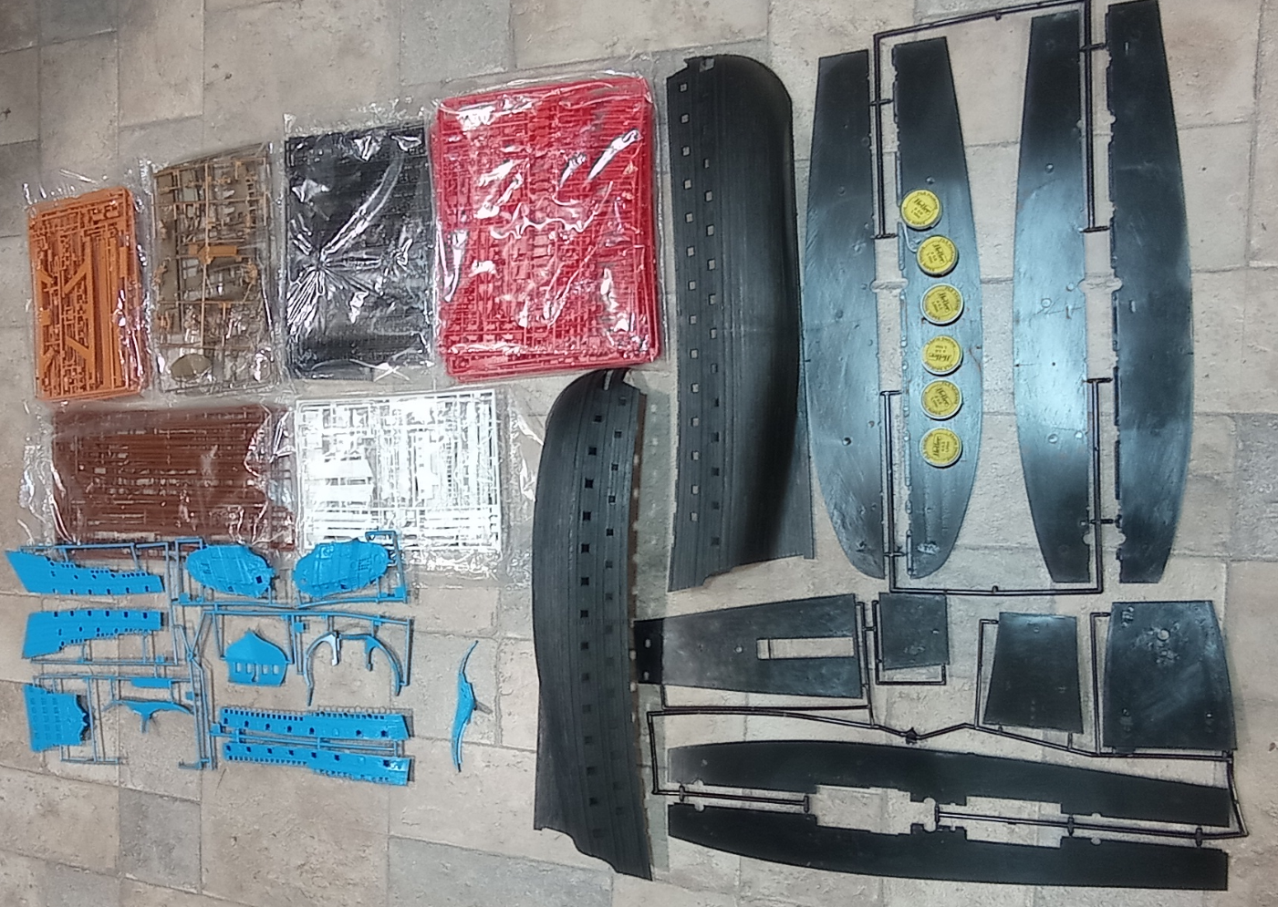
Prelude So, another journey begins. I received the Soleil Royal kit last week after snapping up a reasonably-priced offer on ebay. The kit is one of the older Heller Humbrol pressings dating from 1980's to 2000's. It looks like a very good pressing, I haven't noticed any bad flash and the plastic seems nice and bendy. I've wanted this kit for quite a while but, because it gets mixed views, had planned to leave that for a good few years yet and, perish the thought, try to actually finish one or two other builds first. However, having foolishly opened the box, I'm already on the slippery slope. The plan is to cogitate here for a while before doing any building, drawing on the logs and input those who have built or are in the process of building this kit, particularly Bill's completed log, as that'll be the best step by step going, and Marcs amazing partial scratch build. I have several models on the go, along with a host of other non-model-making projects, and in another 4 or 5 weeks I will retire from career number 3, take the pension and, in theory, have all the time in the world to finish everything off. Famous last words. If the last few months of semi-retirement are anything to go by, I'll be busier post than pre - I seem to be collecting new projects and hobbies at a frightening rate these days. In passing, about a year or two back I decided to replace our ancient and unreliable digital SLR camera and what I landed on (though not by accident) was something that would allow focus stacking. The camera and lenses also happen to weigh slightly less than a party balloon and, in the event, this has triggered an unexpected return to photography as a major hobby. On any day when the light looks interesting, I'm much more likely to disappear off to somewhere with photos to be had than stay hunched over the workbench. So, as I don't have any pretty Soleil Royal pictures to post today, and probably won't for quite a while, let me take the liberty of including a pretty flower instead. The picture of the Iris is not entirely irrelevant. I love the subtleties, nuances of shade and colour contrasts that you see in flowers when you look at them up close. Nature never gets it wrong. What attracted me to the Soleil Royal was not the picture on the box, or sight of a completed build, but Marc's (Hubac's Historian) interpretation based on his extensive research. Such beautiful colours, contrasts and shades. I'm sure I'll be stealing many ideas from his log. That's is not at all to suggest I can paint at that level. (Bill, if you're Larry Da Vinci, I'm your younger brother Les: handy to have around if you need a bit of plastering or concreting, but my best ceiling paintings have involved a 7" roller, a tub of magnolia and a steady supply of tea). However... what I love about painting plastic is that, as I have discovered, it comes off oh so easily with a bit of isopropyl alcohol and elbow grease, so you can try as many times as your patience permits! As my other logs demonstrate, I'm not too bothered about historical accuracy and I use 3D printing to remake parts that I think can be improved on (and to circumvent my artistic limitations!). This is both a blessing and a curse. A lot of things seem very simple to remake at first, but turn out to be quite complicated once you get into them. Sometimes that's because 3D printing is not always the best suitable tool for the job. I'd love to have a CNC mill but I can think of many better things to spend £1000 on! A little task I need to pursue is to try resin casting - I bought a starter kit a few months back but haven't had time to mess around yet. Anyway, part of the purpose of the cogitation period is to take stock of the kit and try to decide in advance what I want to remake and what I don't, and how. I bought a laser cutter/engraver last year (long story, one of those go-fund-me type of deals) so I will certainly do veneer decks and a few other things. Anyway, log started, let's see how we go.

-
Strange. Is some kind of AI bot parroting my post?
-
That sounds like good advice. Contrary to appearances the bit I enjoy learning the most is the painting so I’ll be inclined to follow Marc’s lead to some extent, but I also really like the white hull so maybe that too; even though I hate painting white in acrylics! I think this is one for me to study, read and chat a lot before starting, so I’ll create a build log and copy across this conversation as I’m sure there will be plenty to talk about. Oh, and it goes without saying that I’ll be going back through each of yours logs in detail.
- 1,508 replies
-
- 1
-
-
- Le Soleil Royal
- Heller
- (and 1 more)
-
Thanks - hopefully not so much that I feel compelled to remake the stern. The Victory has been hard enough!
- 2,667 replies
-
- 1
-
-
- heller
- soleil royal
- (and 9 more)
-
Bill, I've just taken delivery on my SR kit - very tempting to just dive in! A quick question - did you find the new instructions particularly useful? The old printed version looks pretty good so far as I can see. And what would be your top tips if you were starting the kit all over again? Is there anything you regret doing, or wish you had done?
-
My SR kit has arrived; contrary to expectations, the pressing looks at least as good as that of the Victory, no flash or distortion evident on a quick once over and the hull halves seem to fit together quite nicely. What am I missing? I've always been under the impression that the SR was of a lesser quality than the Victory, which was part of the reason I'd always planned to do this last, when I had more experience?
-
That's interesting, I wouldn't have thought to dilute the blackener, though I was going to try soaking some rod in ketchup or brown sauce as a de-oxidiser. I'm sure many on here used to do this with the old copper coins back in the day, to make them look new.
- 2,667 replies
-
- 1
-
-
- heller
- soleil royal
- (and 9 more)


