


Kevin-the-lubber
-
Posts
1,232 -
Joined
-
Last visited
Content Type
Profiles
Forums
Gallery
Events
Everything posted by Kevin-the-lubber
-
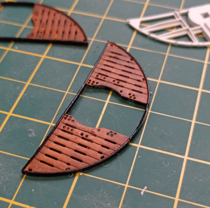
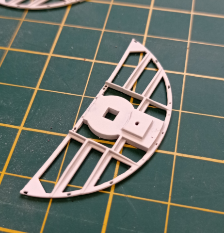
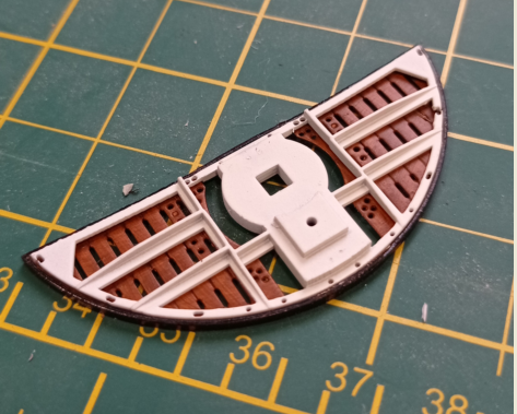
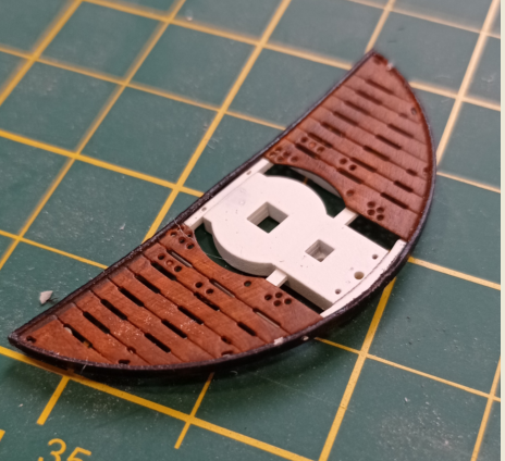
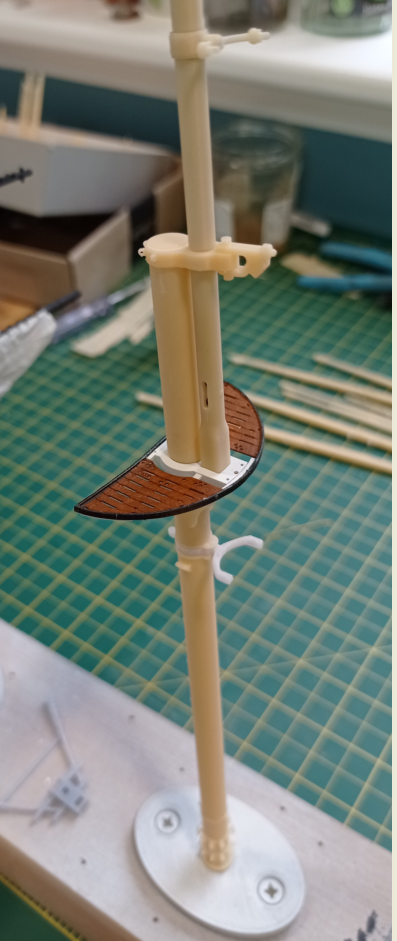
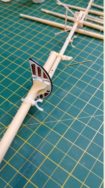
 Hello all, checking the log, it looks like I've been working on the mast assemblies for around 9 months now (started at post #352), though a fair chunk of that time has gone on other, non-modelling things. No wonder I'm beginning to feel bored, though not yet to the extent that I'd park the model. I ran into difficulties with version 1 of the mast assemblies: some of the more delicate parts proved too fragile and I needed to find better solutions. To cut a long story short that's led to redesigning the way a mast assembly fits together and I'll post on all of that eventually. Meanwhile, redesigning has sometimes led to an incidental improvement, one of which I'll post on today, just because I feel more like writing than thinking! Tops While re-working these to accept a square carbon fibre mast stiffener, rather than round CF rod (hence the square holes in the white frames), I realised I would get cleaner prints and sharper paint lines if I made these as a two-part sub-assembly. Once the parts are painted, the white 'iron frame' sits snugly within the wooden platform and, with a few dots of glue, the whole has fairly good rigidly. Why so many when I only need two? Because these are extremely thin and a small lapse in concentration or even just a bit of bad luck can see them break at any point. I dislike having to stop and make a new item from scratch so I often make extras to begin with. It takes the same time to print 6 as 2, the cost is relatively insignificant and I also tend to do each operation ( cleaning up, painting, glueing) a little better as I work through the collection. It's a shame the spares end up in the spares bin but that's the nature of the beast.
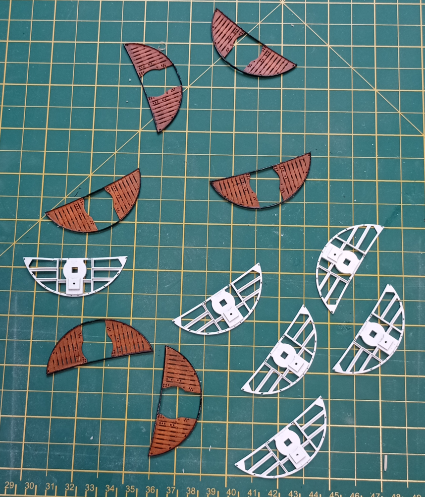
- 444 replies
-
- 6
-

-

-
- Cutty Sark
- Revell
- (and 2 more)
-
This is amazing, I followed the link from the 'At A Glance' thread and would never have guessed this was a card model. You have piqued my interest!
- 45 replies
-
- 3
-
-

-
- Earnslaw
- Paper Shipwright
- (and 2 more)
-
That sounds fabulous! Was that a canoe trip or in something more comfy? I’ve wanted to visit that part of the world for ages, but am getting a bit old to be doing things the hard way now.
- 536 replies
-
- 2
-
-
- Quadrireme
- radio
- (and 1 more)
-
Books to learn Fusion 360
Kevin-the-lubber replied to allanyed's topic in CAD and 3D Modelling/Drafting Plans with Software
Dave, great model and I’m jealous that you have a Bambu for printing. Speaking for myself, 99% of the learning curve in f360 is around specific methods and when it gets to hulls, the more complex end of f360. For instance, how do you use splines, how do you project lines into thin air, that sort of thing. This is where Kevin Kennedy and Lars are usually so good. I think a voiceover is essential. Back when I was mostly learning, I watched a lot of vids and kept coming back, mostly to the former, because he explains topics very well. Somewhere on YouTube there’s a very long, detailed screencast video of a chap modelling a hull in F360, but no voiceover and it’s almost impossible to understand what he is trying to show sometimes. That’s a great shame because there is definitely a gap for a tutorial around hull creation, when to loft, when to sweep and especially how to fair the basic shape. You’d be doing a great service to humanity - well, a small slice of it if we’re honest - by taking on that task! bw Kevin -
I think you could probably tie those sails to a lamb chop and people would still say "wow". Put them on a build of this quality and they're something else. Bruma, a query - it looks like you've gone for painting the masts white and 'wood (teak?)', is that right? If so, what decided you to go that route? I'm torn: on the one hand, on the real ship they are currently white/red ochre, and it doesn't look as though the red ochre is a primer; whereas Sankey (painting the cutty sark) says they were originally white/black, rather than the white/teak that was often depicted in paintings. I'm looking for a good excuse to go with white/teak, other than just personal preference! I recognise that the current masts are steel all the way (unless they changed to alloy after the fire), so faux teak would be a bit pretentious, but it's an unattractive colour all the same.
- 399 replies
-
- 1
-
-
- cutty sark
- revell
- (and 2 more)
-
What a nice thing to say!
-
This is getting exciting! It sounds like it's coming out very similar to the real thing, and I for one will be really keen to see video. In the movies, galleons (and longboats) always look absolutely planted in the water and tear long at speeds that might tempt me to slip on a pair of water-skis. Steven's description brings it all down to earth though. Beside the full-size replica of the longboat in Norway was a large-ish model in a perspex case. Maybe, when you've had enough of it, you could offload it to a museum? You'd think it would be quite interesting to see a galleon actually moving through the water.
- 536 replies
-
- 4
-
-
- Quadrireme
- radio
- (and 1 more)
-
Usernames are, for me, like passwords - I always struggle to come up with something and kevin-the-lubber was a very off-the-cuff choice. It's fine for forum use but if I do manage to open a little 3D parts shop it's not a great label, is it! Anyway, I'm still pondering on it so we'll see.
-
I'm glad the photos are proving useful, they've certainly been invaluable here. In case any of you are wondering why my log is so relatively quiet, it's because I'm doing a further, much less fragile iteration of the masts and yards and it's more difficult to remain motivated day after day when it's version 3! But I will get there, eventually. Great explanation of the 'T-shirt'! So I wasn't so far out at all! As I'm almost certainly omitting sails (just too hard for me) I think I'll include the 'cutty sark', the star and the main flag, but I completely agree that you have to take what you see at Greenwich with a pinch of salt.
- 399 replies
-
- 1
-
-
- cutty sark
- revell
- (and 2 more)
-
Thanks Rob, correct nomenclature is not my strong point - but at least I've progressed slightly from calling everything 'thingy's' 🤪
-
Quick question - if I change my username (to something a little more grown-up!), will this break the link for anyone following my builds? Or will they automatically update?
-
The tin canning effect is very realistic, Richard. That is one big ship!
- 454 replies
-
- 1
-
-
- Union Steamship Company
- Stepcraft 840
- (and 3 more)
-
That is a very well-observed photo! The ship (the real one!) looks nice too. Where did you/does the ship sail?
-
It brings the section to life, they now look like they are in conversation.
- 2,699 replies
-
- 3
-
-
-
- heller
- soleil royal
- (and 9 more)
-
Now that I can see the workshop items I can see how large this is - it's BIG! What are you going to do with it after it's completely finished and proven? I'm also struck by the slight similarity to a beautiful, full size replica Viking boat I saw last week in Norway - the high prow and stern, gazillions of oars and so on. Just trying to tempt you to look at a variant, after this one 🙂. (https://sagastad.no/en/the-history/the-myklebust-ship/) At least your cat looks like it settles. Ours, which is not even actually ours - it belongs to a neighbour but treats our place as its daycare facility - constantly prowls, howls and demands attention.

- 536 replies
-
- 3
-
-
-
- Quadrireme
- radio
- (and 1 more)
-
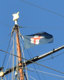
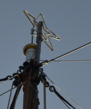
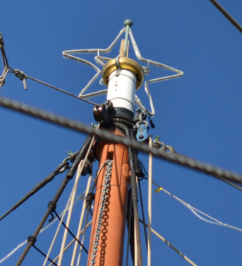
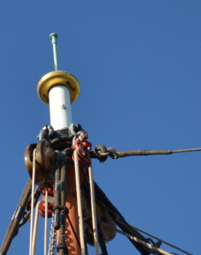
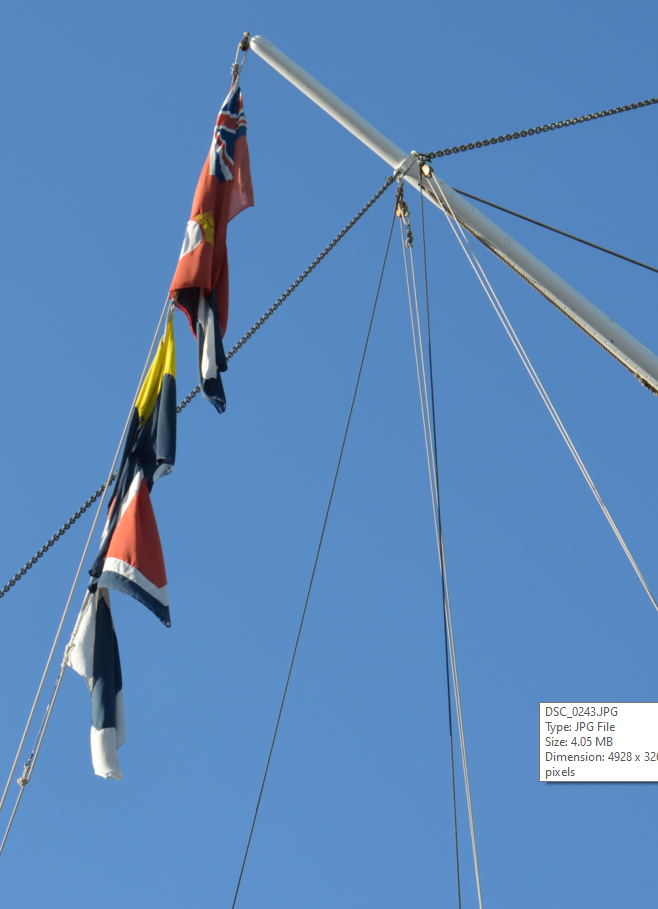
That's quite a complicated arrangement, isn't it! I was going to just stick some of the following onto the masthead via a centre hole, but this is a timely post as I'm in the middle of a design revision, for reasons I'll cover when I eventually finish. As I'm not including sails and therefore haven't really looked at the sail plan, I hadn't even noticed that Campbell shows a flag, but there it is. Did you download the photos I uploaded to dropbox a while back? If not, looking at them now, I can see a flag on the mainmast but also this strange 't-shirt' shaped metal thing, which I also saw in the display down in the hold. It signifies something but I don't remember what; On the foremast, I see a star shaped metal thing, mounted on a pigstick (now that I know what it's called!); The mizzen just has a metal spike, but there are sheaves present ; and for info, these flags were on a line coming off the gaff. I'm sure someone will know what they say.
- 399 replies
-
- 4
-
-
- cutty sark
- revell
- (and 2 more)
-
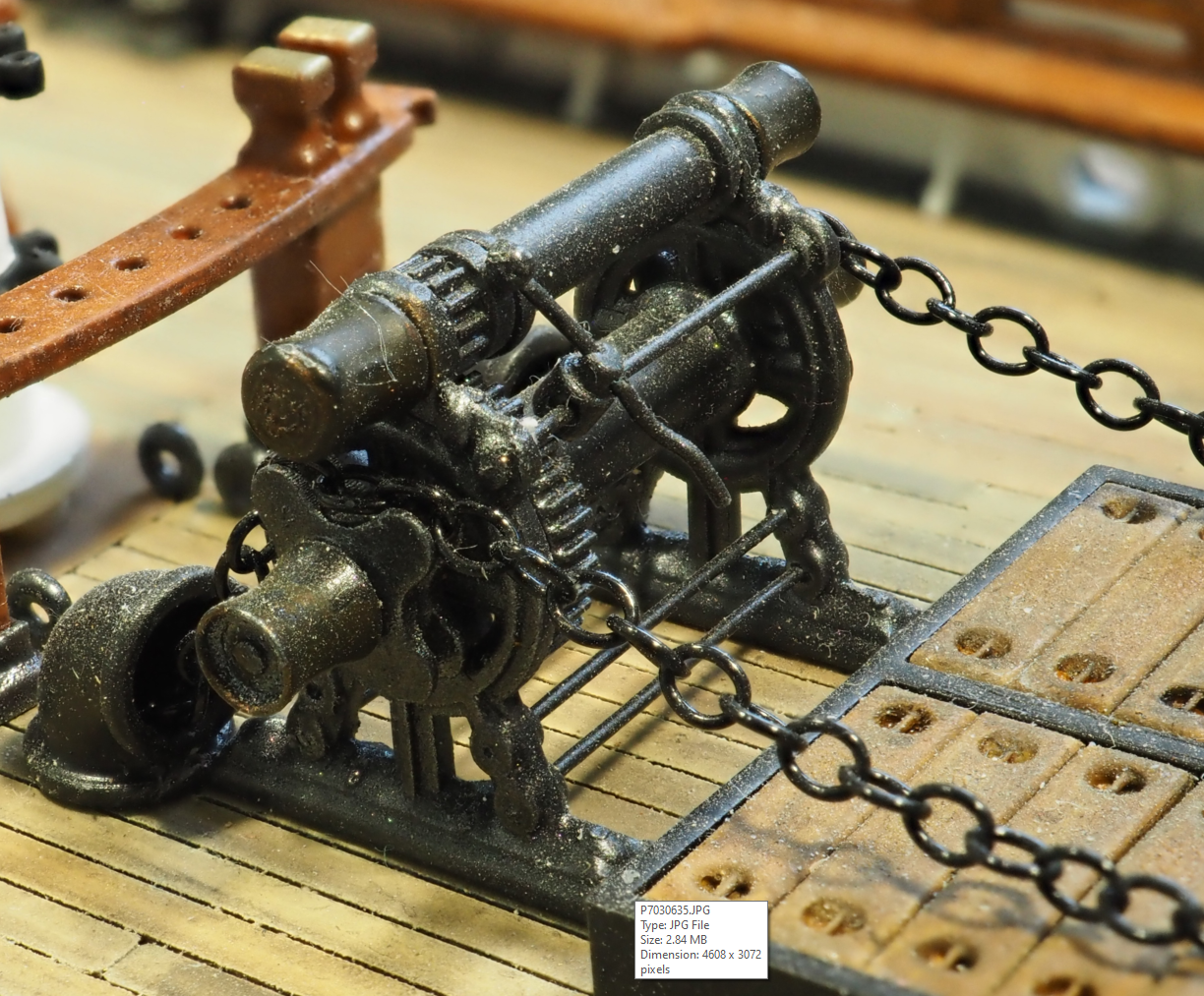
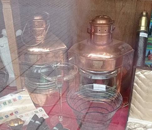
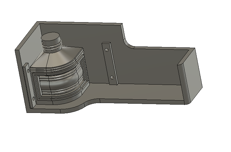
Once the anchor is catted I assume the chains would rest on the deck. Presumably the crew laid them beside the hatch and perhaps tied them off so they didn't move around in heavy seas. On a slightly different note, I was in Haugesund in Norway last week and spotted these beauties in an antiques shop. Unfortunately it was closed and I was only there for a few hours, or I'd have been sorely tempted. The funny thing is that I've only just finished modelling these myself.
- 444 replies
-
- 4
-
-
-
- Cutty Sark
- Revell
- (and 2 more)
-
Marsalv, I've picked up a signpost to this build and it's fantastic. I haven't yet read through from the beginning but you are making me very keen to purchase a CNC mill & lathe. That said, it's one thing to get the machine to cut the parts, quite another to bring them all together into such a gorgeous model. One question (which may be answered if I read the whole log) - have you got all of the critical design information from the monograph? I've never even seen a monograph but it sounds like something I'd like.
- 589 replies
-
- 2
-
-
- le gros ventre
- cargo
- (and 1 more)
-
Marc, it appears that Marsalv is milling the parts i.e. the lower filling parts on Page 1. Although the methods and machinery are different, the engineering processes in milling (CNC especially) and 3D design & printing are not very different. Though to be honest I've still only had the quickest flick through his log as I always seem to have three or four things on the go at the moment. At 6 feet x 5 feet you might need to negotiate who gets to build what!
- 1,508 replies
-
- 1
-
-
- Le Soleil Royal
- Heller
- (and 1 more)
-
Interesting conversation here over the last week, I’ve enjoyed reading it! I was an absolute dunce at school, especially at maths (as we call it this side of the pond). The game changer was learning trig, which was an essential part of my trade (fabricator-welder). Nice link from Marc to the Le Gros Ventre build, which is indeed gorgeous and one which I’ll now follow too. I know I am meandering towards something bigger with my 3D work and that build log has crystallised my thoughts somewhat. What struck me straight away (apart from the quality of the build) was that he’s doing in wood what I’m doing in plastic. Interesting, especially as I’ve just bought a laser cutter. Looks like I need to start browsing monographs. Regarding masts and yards Bill; I’ve completed version 2 of these for my Cutty Sark (a version 3 is in the pipeline for reasons I’ll cover in my own log), but I consciously chose an ‘off the ship’ approach just because there’s less clutter, less risk of a sleeve catching on something elsewhere on the model. Your SR is looking fabulous, and I think you can easily afford to take risks now.
- 1,508 replies
-
- 1
-
-
- Le Soleil Royal
- Heller
- (and 1 more)
-
I’ll probably mull on this for a while and perhaps make some modification - at my current rate of progress I have about 15 years to think on it before declaring the ship finished 😃.
-
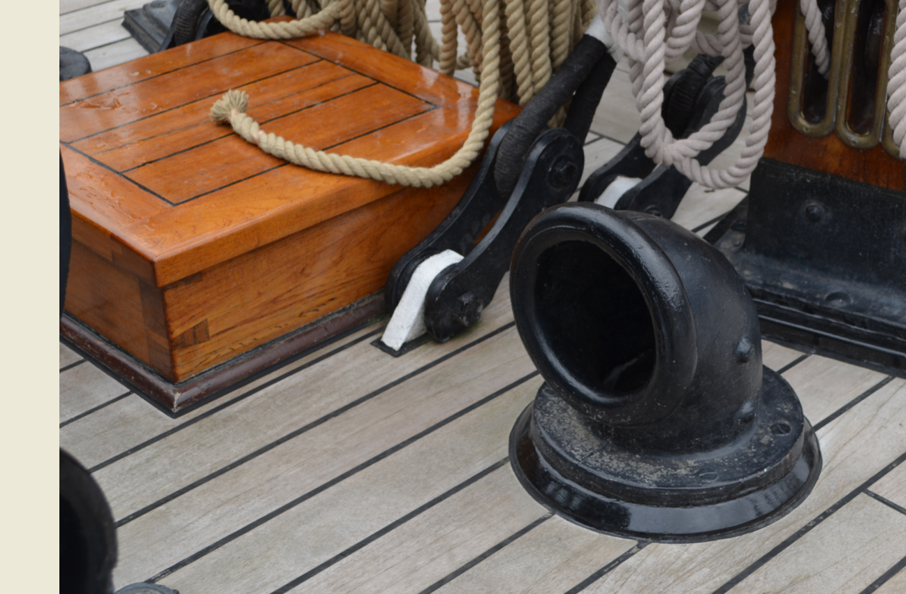
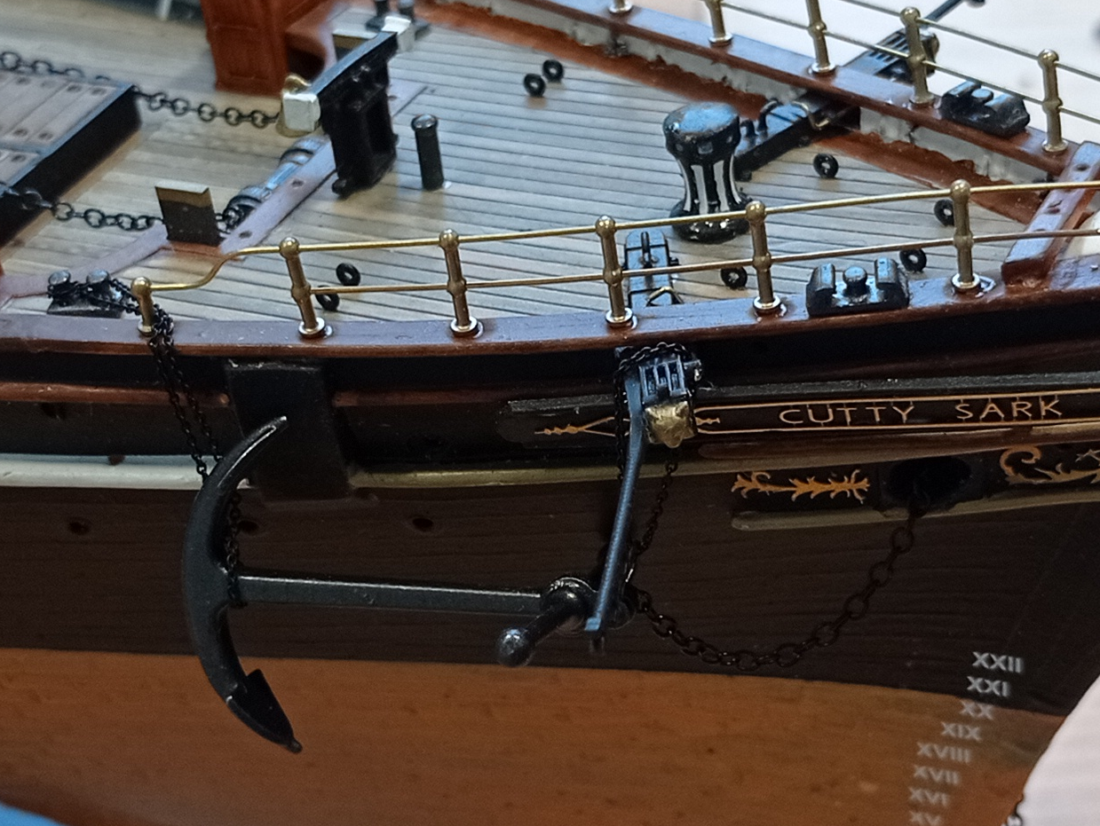
Re the chains ripping up the hatchway, my personal view is that we're all a little misled by some erroneous drawings by the likes of campbell. All of the plans I've seen so far have been, essentially, artistic interpretations rather than engineering drawings. I think that engineering drawings would have shown what any engineer would have done with this hatch, and shipbuilders were nothing if not engineers; they'd have done what the restoration team did, as per the photo below. A small hatch in between the chain pipes. There's a much larger hatchway forward of this but that also doesnt interfere with the run of chains. I say all this because, as an engineer by trade and nature, I would never have been able to do something as stupid as having a chain this big run like that! Johnny, I do the same, to the death, and in the interest of not being struck by paralysis through analysis, I'm now just committing and, as often as not, almost immediately uttering expletives when I realise what new but utterly obvious thing I've missed. There's probably some kind of existential law around this, that says it is physically impossible to see the looming error until you've made it. The other thing that now does my head in is breaking things. As I withdrew my forceps and tweezers from slipping that tiny chain into the real, actually working, release mechanism on the cathead, smugly thinking 'nicely done, sir', "ping", off snapped the tip of the jib boom, never to be seen again. It'll be with the hinge brackets for the spanker yards, the previous versions of the catheads, numerous stanchions and countless other parts that are a right pain to remake. How did I snap the jib boom tip from there, you ask? Well, if you can figure it out please do let me know because I'm damned if I do 🙂.
-
I managed to grab an hour today to work on the anchor chains. I have to say I'm deeply unconvinced by the chain running to the bollard; would any self-respecting sailor ever trash the rail or stanchion like that? I don't think so. I'm not going to move the bollard or rail now, but I might yet put an eyebolt in the hull aft of the aft of the flukes as that's how Campbell has it. Half the problem is that plate where the fluke sits (I've forgotten the proper name). When I altered the foredeck to match Campbell, I ought to have also moved that. Such is life.
- 444 replies
-
- 2
-
-
-
- Cutty Sark
- Revell
- (and 2 more)
-
I always enjoy looking over your recent adventures Daniel, they bring the ship to life. In my mind, I’m transposing all those little characters to the real ship as real people. Gosh but it must have been a living hell inside a warship, which is something I think we tend to ‘erase’ in our very pretty models.