


Kevin-the-lubber
-
Posts
1,232 -
Joined
-
Last visited
Content Type
Profiles
Forums
Gallery
Events
Everything posted by Kevin-the-lubber
-
 And to think, in a few years much of that will probably be readily available to you and I at an affordable price. I went to a local Hobbycraft store a week or two back, don’t know if you have these on your side of the pond but over here they are hobby superstores that cover everything from knitting to jewellery making to oil painting. They were selling plywood, leather and acrylic blanks for laser engraving. That’s how mainstream some of this stuff has become. I kind of wish I was 30 years younger with a bit of capital, I’d open a small 3D shop in our (dying) town centre, and make things to order. There’s gold there, folks. While here I may as well update; I’m having one of those spells where work is intense and I don’t have the ‘zing’ in the evenings to complete the slightly dreary next stages of the Cutty Sark. Plus I’m distracted by the arrival of the laser machine. I’ve already made enough bird boxes, room signs, key fobs and place mats to have Christmas and birthday presents covered for a few years, and have begun messing around with a CS wood veneer deck with an eye on recovering my outlay. So, a little dormant but still on the slips.
- 444 replies
-
- 1
-

-
- Cutty Sark
- Revell
- (and 2 more)
-
Wow, that’s one great library. I think I need to relocate to Canada! I often find it’s better to split parts, especially in filament as I dislike the ‘scars’ from supports. These are more easily mitigated in resin. Regarding the galley itself, thumbs up on the modified steering platforms. Just a thought - I have absolutely no knowledge of what they would have looked like but might they have been a bit rounded, kind of chariot-ish? The eagle will look very good and should be fairly easy to bash.
- 536 replies
-
- 2
-
-
- Quadrireme
- radio
- (and 1 more)
-
Ian, this is a fascinating way of incorporating various tech. That’s a really good idea re’ transparent filament for the rudder. Out of curiosity, how much does the library charge you to print or etch something?
- 536 replies
-
- 3
-
-
- Quadrireme
- radio
- (and 1 more)
-
Focus Stacking
Kevin-the-lubber replied to Dennis P Finegan's topic in Photographing your work. How to do this.
Early this year I switched from a Nikon D5100 to an Olympus OM-D ME5ii, and this has completely revived my interest in photography (somewhat at the expense of modelling!). Being micro four thirds (MFT), everything is incredibly light and comparatively small and I happily carry the camera around with me most of the time. I think part of the reason I didn’t carry the Nikon was bulk and weight. The relevance here is that I bought it because I specifically wanted built-in focus stacking but at an affordable price. Everything new was far too expensive but along the way I learned that Olympus have had this feature on their mft’s for quite a few years and there’s a ready supply of used bodies and lenses. Although some may get sniffy about the smaller sensor, I doubt any of my photos will ever get printed on billboards and the image quality is excellent. I’m also very happy with the focus stacking, in fact it probably exceeded my expectations. -
Focus Stacking
Kevin-the-lubber replied to Dennis P Finegan's topic in Photographing your work. How to do this.
I just set one of the functions buttons on my little Olympus to focus stacking as I stack so frequently, meaning I can switch between stacking and single shot at the press of a button. The camera does a pretty good job of it, I just wish it didn’t keep the base images as it’s a pain deleting them. However, the posts about the stick & graph paper and bellows are food for thought. The former will see me carefully inspecting those areas when I’m attempting display quality shots (macro is my forte) and the latter has me thinking I could probably use a set of those. -
When you’ve finished with your brother can I have him please. I still haven’t got my head around Blender and all that stuff, I remain strictly ‘engineer-grade’ and at some point will have to learn how to do figureheads etc. I’m sure he could tell you how to deal with that eagle but what I’ve done in the past was to download Meshmixer (it’s free) and use that to reduce the number of polygons etc. That said, you won’t need to cut it up for resin printing, you’d just need to do something for mounting on the ship.
- 536 replies
-
- 2
-
-
- Quadrireme
- radio
- (and 1 more)
-
That’s a fantastic price. I assume this is the Halot-Mage, which is also available as a great BF deal here at the moment. However, as my Elegoo Saturn is more or less the same size there’d be no sense in buying this, much as I’m tempted. If your brother is good with Blender or something similar you should end up with wonderful, unique figures to go with this unique build. Actually, I remember there’s an amazing app for making figures called Daz3D, in case it’s of interest.
- 536 replies
-
- 4
-
-
- Quadrireme
- radio
- (and 1 more)
-
CNC Desktop Router Reviews
Kevin-the-lubber replied to tmj's topic in CAD and 3D Modelling/Drafting Plans with Software
You’re probably right there, for a good while I thought about changing horses as some of the shortcomings of F360 really frustrated me, but over time you get so used to avoiding the potholes that you forget they’re even there. My guess is there are comparable bugs in every package, these are, after all, the most incredibly complex bits of software. One of the things that has kept me using F360 is the timeline. In my view this is probably it’s best feature, especially for modelmaking work, where I often need to make it up as I go along and have to tweak the design several times until I get it right. Mind you, it’s a skill in itself to plan the design workflow so that everything downstream does just update, rather than break. -
Ian, I'd gently encourage you to take a look at Fusion 360. I made that step when I was finding my TinkerCAD designs were becoming just a bit too complicated and I couldn't quite get what I wanted. It sounds like that's where you're at too and, if I may make assumptions, I sense that you are quite interested in this stuff (printing, lasering) so you'll end up there sooner or later anyway! I think you'll get to be able to do most of that design fairly quickly, within an hour or two, the slightly harder bit (maybe) will be the decor, but you can sing out if you need to. I share this link quite often, because I found it to be a first rate 'printed' tutorial, as opposed to the equally excellent Kevin Kennedy videos and I need to be able to read and repeat the steps on day 1: https://diyodemag.com/education/exploring_3d_part_1_beginners_guide_to_fusion_360
- 536 replies
-
- 2
-
-

-
- Quadrireme
- radio
- (and 1 more)
-
Thanks both, I’ll file that away in my memory for when we eventually revisit Amsterdam.
-
That’s really not bad going using TinkerCAD. I think all CAD is quite difficult at first and that quite an advanced shape. I hope the print comes out well, I imagine it’s a filament printer so you’ll at least get a nice, strong ram.
- 536 replies
-
- 3
-
-
-
- Quadrireme
- radio
- (and 1 more)
-
CNC Desktop Router Reviews
Kevin-the-lubber replied to tmj's topic in CAD and 3D Modelling/Drafting Plans with Software
It'd be good to get your reflections and a bit of a running commentary as you go along. Part of what's stopped me leaping in is that I don't relish having to learn yet another bit of difficult software. -
CNC Desktop Router Reviews
Kevin-the-lubber replied to tmj's topic in CAD and 3D Modelling/Drafting Plans with Software
There is one thing I’ve just remembered. When you set up for the first time, you can set mouse behaviour to be the same as whatever software you’ve come from. In my case it was Tinkercad and I’ve never got around to learning the F360 default settings. -
CNC Desktop Router Reviews
Kevin-the-lubber replied to tmj's topic in CAD and 3D Modelling/Drafting Plans with Software
Tom, this may help https://diyodemag.com/education/exploring_3d_part_1_beginners_guide_to_fusion_360 although if you're using AutoCad it may be a bit basic for you. Either way, yes, the learning curve is steep but generally rewarding. Top tip: when F360 hangs for more than 10 seconds, ctrl+alt+del, most of the time it doesn't find a way out of the jam and the hoping and waiting is plain frustrating. Main thing that makes it hang; patterning, especially in drawings. It hates it. -
CNC Desktop Router Reviews
Kevin-the-lubber replied to tmj's topic in CAD and 3D Modelling/Drafting Plans with Software
I’m watching the same on eBay, likewise proxxon machines. I can’t advise on either as I have no experience but wanted to throw in these observations. I do a lot of 3D printing, using both resin and filament printers. I’ve been able to make almost every part of my current build (Cutty Sark) using this tech, with a few tricks and turns along the way. But, there are some parts where, above all, you need the part to be strong. This is where a milking machine would be the solution. Or a milling machine. (I thought I’d leave that particular auto-correct in, as it made me laugh so much. And people think AI is going to rule the rule? The outcomes may be more interesting than we expect.) You can resin print with the necessary material properties but you have to shift from hobby machines costing a few hundred $ to industrial equipment or paying a lot for someone to print for you. I’ve also just taken delivery of a laser machine that would retail at maybe $500. For that money it’ll cut 12mm (1/2”) timber but still only engrave metal. I believe it doesn’t actually etch metal, just burns the surface to achieve a colour change. The point being, getting the laser equivalent of a milling machine costs way more than I’ve spent. Whereas the Gemitsu is available for around $400 - $500, and the proxxon for a bit more. So personally, sooner or later I expect I’ll go for it and possibly a little lathe as well. -
This one made me smile, Daniel. Very reminiscent of a particular section of your epic Victory build log. The diorama looks incredible, who made all the ships?
-
Focus Stacking
Kevin-the-lubber replied to Dennis P Finegan's topic in Photographing your work. How to do this.
I have an Olympus OM-D E-M5 II which has built-in focus stacking that includes processing the image in camera. I did some tests to compare this with processing via Helicon and various free programmes and decided the difference was negligible, certainly at the sizes I work to i.e. 12 x 10 prints. The camera gives you a choice between the built-in stacking, which takes and combines 8 shots, or stacking for off-camera processing, in which case you can take as many images as you like. For reasons unknown Olympus restrict stacking to only a few particular and expensive lenses, but there is a free firmware hack on the web that allows you to over-ride this. Now, the reason I haven’t included any example pics is because having the right tools is only half the job and, while stacking is indeed a doddle, getting it right takes a bit of practice. I wouldn’t claim to have reached that point with my model photos yet. Nor my modelling for that matter! Dziadeczek, are you running a build log anywhere? I ended up here because of your ‘at a glance’ entry and I’m keen to have a closer look at your sails! -
I kind of wish I'd had it earlier on the CS journey. I think I'd have at least made the decks and all the deckhouse parts but there are a host of other things worth trying as well.
- 444 replies
-
- 1
-
-
- Cutty Sark
- Revell
- (and 2 more)
-
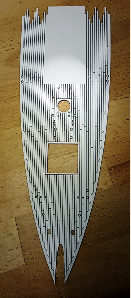
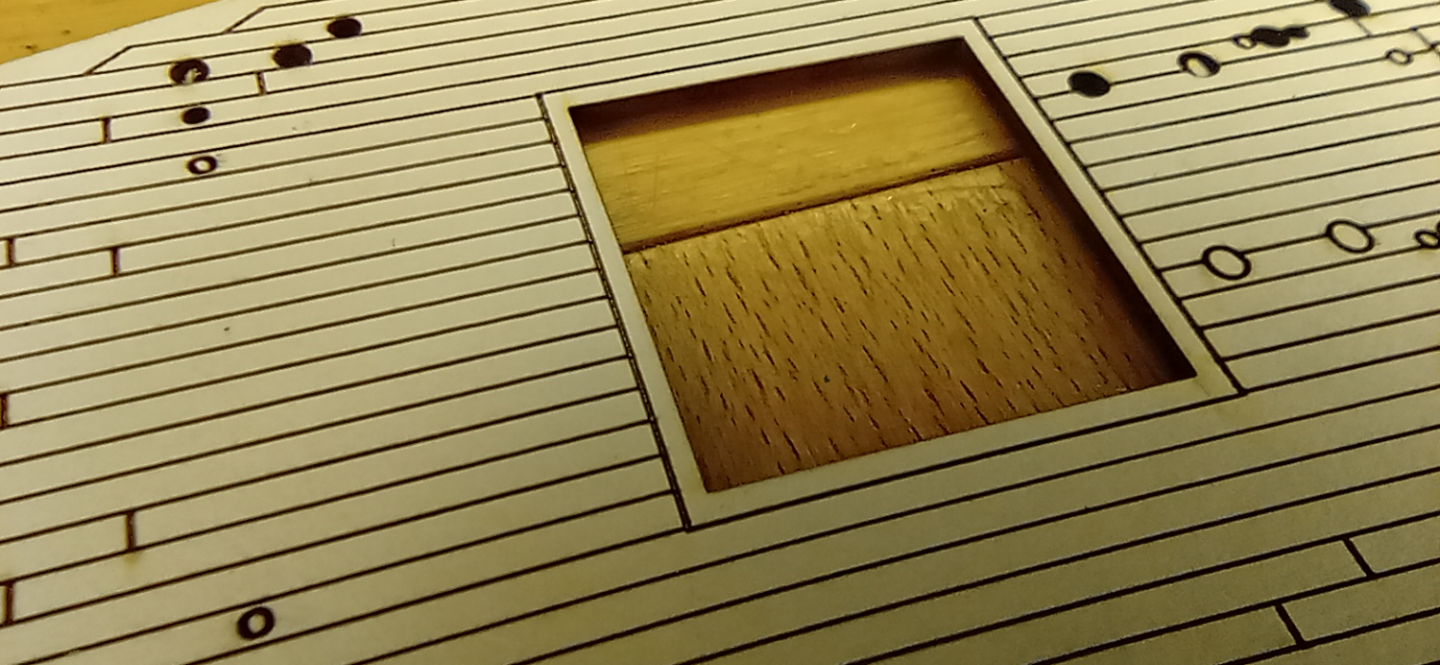
I bought a laser machine earlier this year through one of those start-up sites. I knew it would be 6 or 7 months until I'd receive it but as I trust the company and was getting a huge discount I thought it worth the wait. Anyway, it arrived yesterday and after putting it together, then doing a crash course on Youtube on how to use it, I thought I'd try cutting a Cutty Sark deck section from my print plans, just to see how it would compare. Pretty damn good, that's all I can say. I need to finesse my settings a bit but 12 months ago I'd have happily settled for this. This is cut from card, the stuff you use for framing pictures. That in itself has got me thinking! It more than strong enough for modelling, relatively cheap and dead quick to cut. But when I shift back to the Victory I'll use veneer.
- 444 replies
-
- 2
-

-
-
- Cutty Sark
- Revell
- (and 2 more)
-
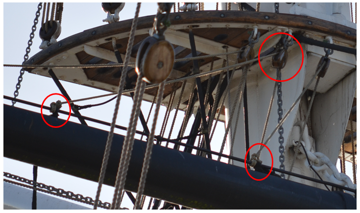
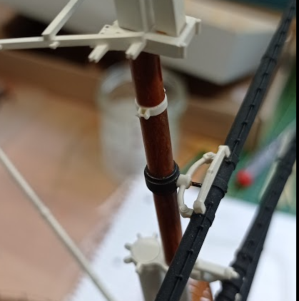
Ian, I guess you're talking about these things; I wondered about these when I took the photos, made a mental note to discuss here when I got to this stage. I absolutely agree that bowlines were obsolete by the time of the Cutty Sark, leastways they're going to be obsolete on this build. (What are bowlines?) Kidding, I'll read Longridge and Underhill next. George, I think I understand that alternative. It's looking unlikely I'll be having any sails though as my experiments in making reefed sails are not turning out as I want, and it's that or no sails.

- 444 replies
-
- 1
-
-
- Cutty Sark
- Revell
- (and 2 more)
-
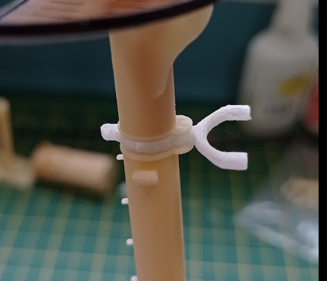
I edge closer and closer to assembling the masts and yards by the month 🙄. All the printing and painting is done, I don't envisage any further design revisions. I now need to add every eyebolt, shackle, block and fixing point to the parts before I start rigging. Drilling holes in situ and on the fly is an absolute no-no on these resin parts, far too much risk of breakage, it all needs to be done in advance. To that end I have been poring over the Revell instructions, both 1974 and 2017, various other instructions (e.g. Airfix, Imai), the Campbell plans, and of course my vast library of photos, so that I have a fair understanding of what gets tied to what, and therefore what eyebolts, blocks and fixing points will be needed. This photo epitomises why I am still left scratching my head and thinking this is still going to be a long old haul (no pun intended). I expect this comes into play when sails are fitted and, in their absence, this is just a 'placeholder', but I wish they wouldn't!
- 444 replies
-
- 1
-
-
- Cutty Sark
- Revell
- (and 2 more)
-
Marco, these last few photos are very helpful for me to understand what additional fixings I need to put on my masts and yards before I commit to assembly. I omitted all the eyebolts apart from those for the jackstays as the load bearing eyebolts will be better made from wire, and I want to do all the hole drilling before I go any further. The ship itself is of course simply fantastic, and the sailwork is the star of the show. You've heard it before but it's still worth saying again, that never before have I seen any sailwork as good as this. They really do look like cloth and, as I touch on below, that's quite an acheivement. Every so often I make another attempt at forming a 'half-gathered' sail like those shown in the second picture of post #361, but no matter how much I make it wet, EzeTissue won't 'sag' or distort enough for this. Did you find the same? I can drag and shape it as much as I want, but when it's dried, if I flatten it out again it is still perfectly true to it's original cut shape. In other words, it behaves just like paper (unsurprisingly) when you seem to have got it to behave a little bit like cloth. I'm also looking at your furled sail on the mizzen. Maybe I need to try a multi-part approach, once I figure out what the parts should look like before being worked.
- 399 replies
-
- 2
-
-
- cutty sark
- revell
- (and 2 more)
-
That looks great, Ian. I bought a laser machine off one of those startup type sites earlier this year, delivery is due this month and I’d expect any future decks of mine to be wood or veneers. You must have a very good library over there.
- 536 replies
-
- 4
-
-
- Quadrireme
- radio
- (and 1 more)
-
Well spotted! That was the very issue I had trouble with. I will do a longer description in time, but briefly, everything except for the weight bearing parts are resin printed. I FDM print the 'stressed' parts and use square section CF as a stiffener. Once cleaned up and painted they look fine. I couldn't do this for the upper topsail crane so for that one I cheat and add a small metal pin that goes through the yard and mast.
- 444 replies
-
- 2
-
-
- Cutty Sark
- Revell
- (and 2 more)
