


Kevin-the-lubber
-
Posts
1,068 -
Joined
-
Last visited
Content Type
Profiles
Forums
Gallery
Events
Posts posted by Kevin-the-lubber
-
-
17 minutes ago, VitusBering said:
Did you make those wonderful catheads?
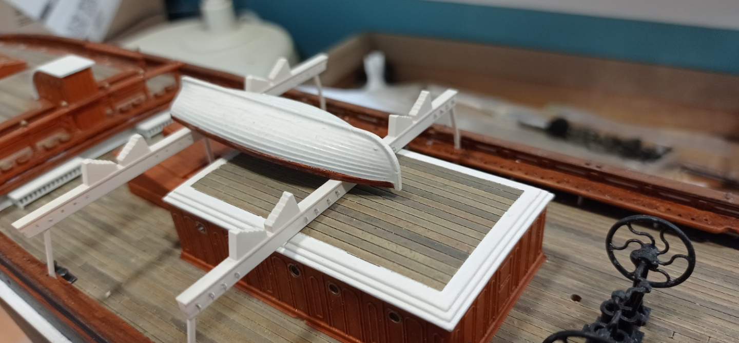
Thank you, I did indeed. I noticed the stepped boat supports during my last visit, liked that and replicating it is straightforward in CAD.
-
Quick question, friends: what would be the 'correct' or, from a modelling perspective, nice way of tying on the boats? As you can see, I have provided a generous number of rings to tie to (tiny twisted wire rings), as I'll be adding boat masts, spare yards etc presently, but I'd like to use a pretty method for tying on the boats rather than completely fudge it. A sketch, however crude, or link to a build log would be appreciated. Obviously it doesn't have to be a CS. I know how I'd do this when tying a load onto my roof rack, though I don't know the name of the knot!
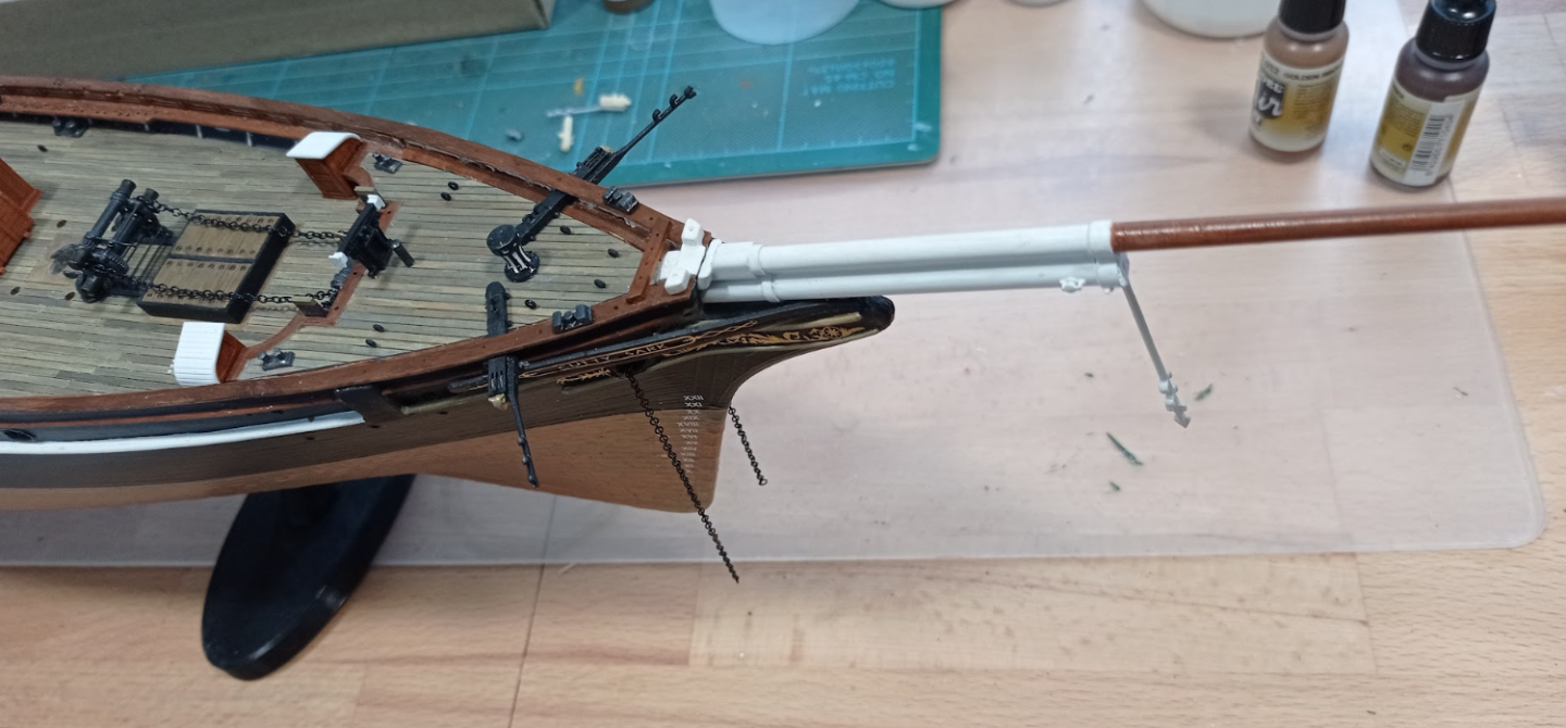
In other news, yesterdays damage repaired, complete with detachable whiskers. I also dug into my reserves of courage and applied the draft decals. I have been ducking this for ages as it's one of those things I felt sure I'd mess up, but I just about got away with it.
-
On 5/17/2023 at 6:29 PM, Ian_Grant said:
Bill, you're right port lids are a challenge on plastic Heller kits. The way they're hinged in reality, when open the outer edge of the top of the lid would just be kissing the outer edge of the top of the opening ie nothing overlaps. On my Victory I added small styrene strips along the top edge of the port lids and left them unpainted. When gluing these strips were aligned with the unpainted top surfaces of the openings, giving a solid glued joint with the lids in exactly the position they would be in when open and the unpainted strips hidden in the hull. Hard to describe in words but I hope you see.
I could be talking nonsense here, it won't be the first time, but one thing I've discovered (among many things) over the last couple of years is how possible it is to drill tiny holes in plastic for tiny wire hinges - I'm talking 0.2mm diameter here, or 0.010" in old money. When I started out I thought this would be nigh on impossible but have found the hardest part is to avoid sticking the drillbits into my fingers 🤪. Anyway, I have it in mind to try that approach when I resume work on the Victory (there are of course no gunports on the CS) in the expectation that the wires should be virtually invisible.
-
You're doing some fabulous work here, Haze.
- mtaylor, Keith Black and Canute
-
 3
3
-
Hi Bill, the one thing Charles & I have in common is we both like cruising holidays - the difference being, he has an entire ship at his disposal, I have to make do with a cabin 🙂. I did take quite a break after surgery. I thought I'd be able to do a bit on a laptop while loafing with my leg up in the air, but that became boring quite quickly. It's not the same as being sat in the workshop surrounded by tools, paints, all that stuff.
Anyway, back on the job now. It’s funny how you can think there’s almost nothing left to do or make and then that ‘almost nothing’ takes weeks and weeks to complete. It turns out I have a whole list of small but essential jobs to do before I fit the masts and start rigging. I’m now well and truly into the ‘fix one thing, break something else’ phase of this model. I seem to break something or other every couple of days and I’m becoming quite good at running repairs. Yesterday, I decided to remove the bowsprit assembly while working on the fore railings as I could foresee the dolphin striker getting broken (again). Of course in the process I managed to catch a whisker boom on my sleeve and snap it clean off, beyond all repair. I've been fearing this since glueing the catheads in place so I’m kind of glad that’s out of the way. It’s given me enough reason to remake the fore rails, which were always a bit wrong, sort out the knightheads, which on revell are a bit strange, and change the design of the catheads so the 'sticky-out' part can be added only when necessary. This allows me to fit and finish the rail and add the outer section of the cathead when I start rigging.
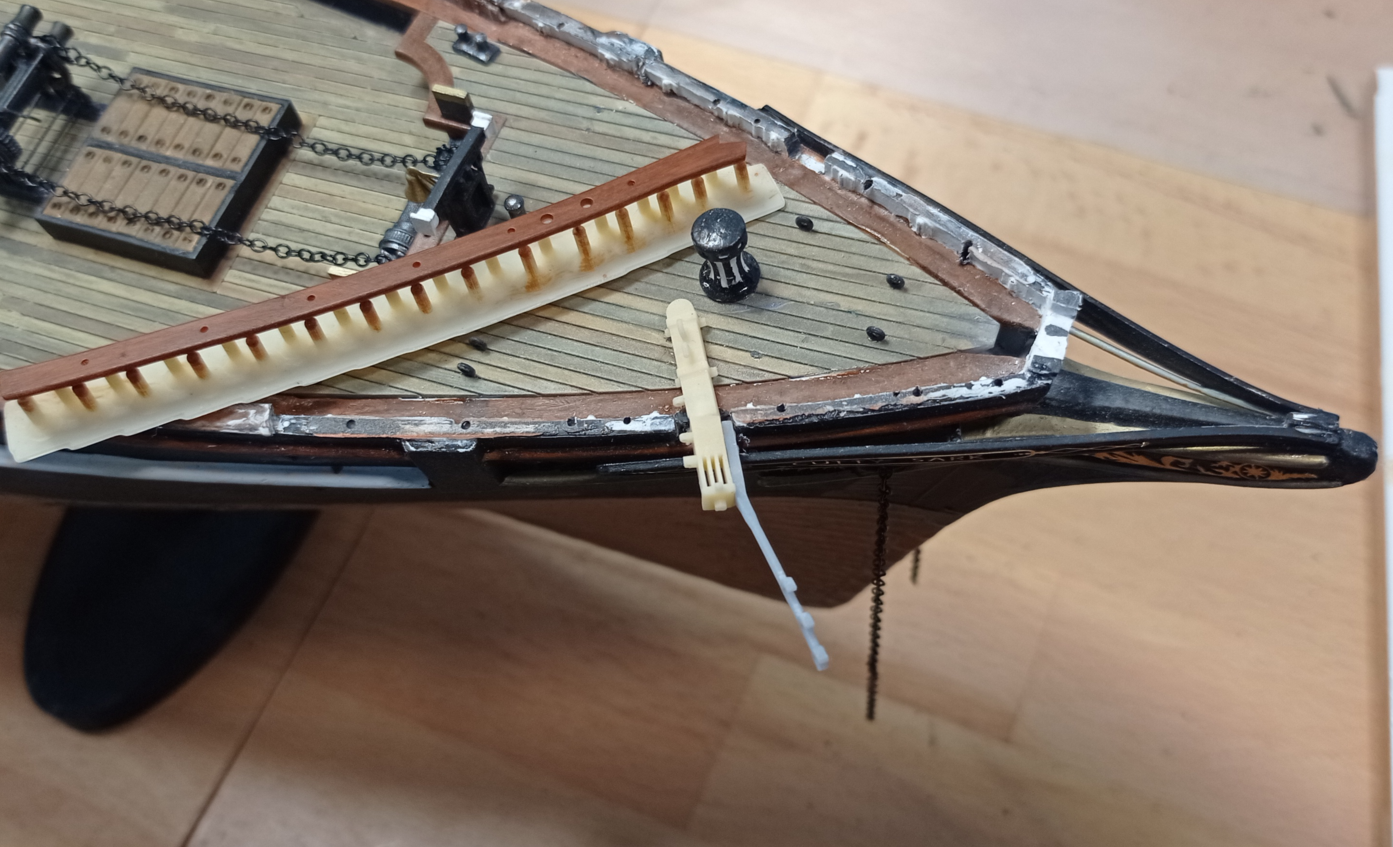
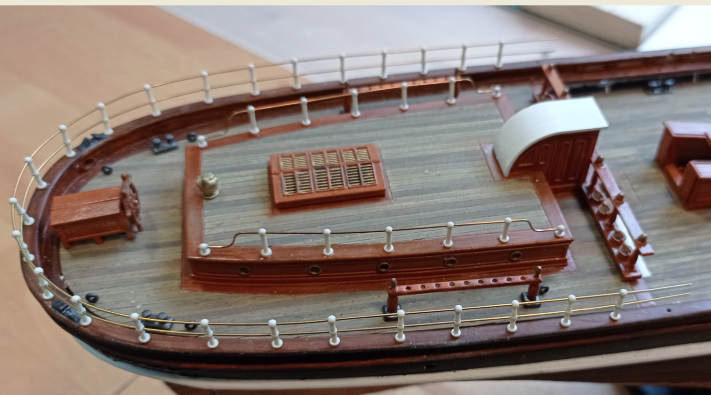
Otherwise, I'm working on the railings. This photo is from a few days ago and is a trial fit, while I shape the wire, especially those end bends. It helps that I can easily make formers, which means all of the ends are identical. At this moment in time I'm intending to use brass-coloured stanchions and leave the wire unpainted, as I like this look. However I could easily change my mind by tomorrow and make it all white!
You're continuing to make great progress on your SR - I also check in regularly and you'll probably finish that before I finish this! That said, I'm content to plod along, I think this is my pace and trying to speed up would be a mistake.
-
Ian, the programme I looked at was Daz 3D. It allows you to create a few figures for free. I haven't really tried it yet, just skimmed the front end but from what I've seen (I think on one of Patrick Matthews logs) it's pretty good. Blender is one of the apps where you basically start off with a round ball of 'clay' and somehow turn that into a figurine. That does my head in 🙂
-
Hi Ian, I haven’t really got to grips with modelling figures. I struggle with the most common platform, Blender, as the tutorials seem to be orientated towards producing virtual product rather than objects for printing. I do also have access to an app that is specific to creating and dressing figures but haven’t given it a proper go yet. For some reason I can’t get excited about doing figures, possibly because this is where it all starts to become more art than engineering and I don’t have an artistic bone in my body!
-
It's been quite a while since I posted but I've now picked up where I left off, so here's a brief update.
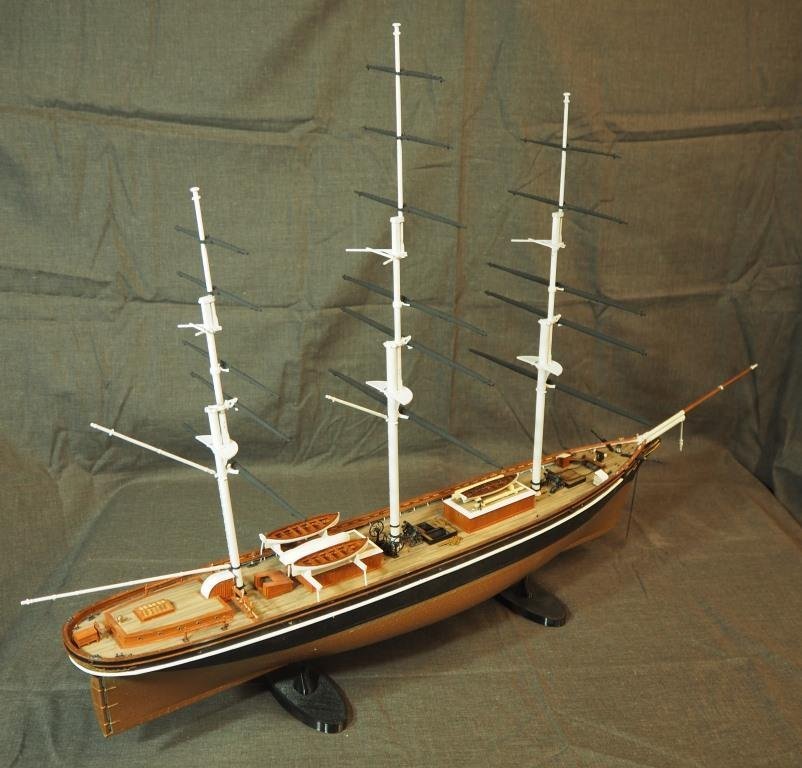
I've remade all the masts, yards, bowsprit, jib boom etc. At the moment it's still the case that the only parts I've used from the revell kit are the two hull halves and rudders halves. I still have a lot of work to do on these (masts and spars) and will do detail photos as and when. Right now the white is too white, I need to paint the tops, make a decision whether to copy the real thing and red ochre the topmasts, etc etc. And then rig them. I'll be doing all that off the ship, I have a dummy rig that helps avoid me breaking bits every 5 minutes.
I've continued to add detail - here, it's the salt water pump on the side of the port WC. Tricky to print!
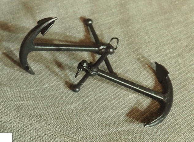
New bower anchors. As with most things now, my new parts are a mixture of resin print, brass or steel wire, carbon fibre and whatever else I need to achieve the objective.
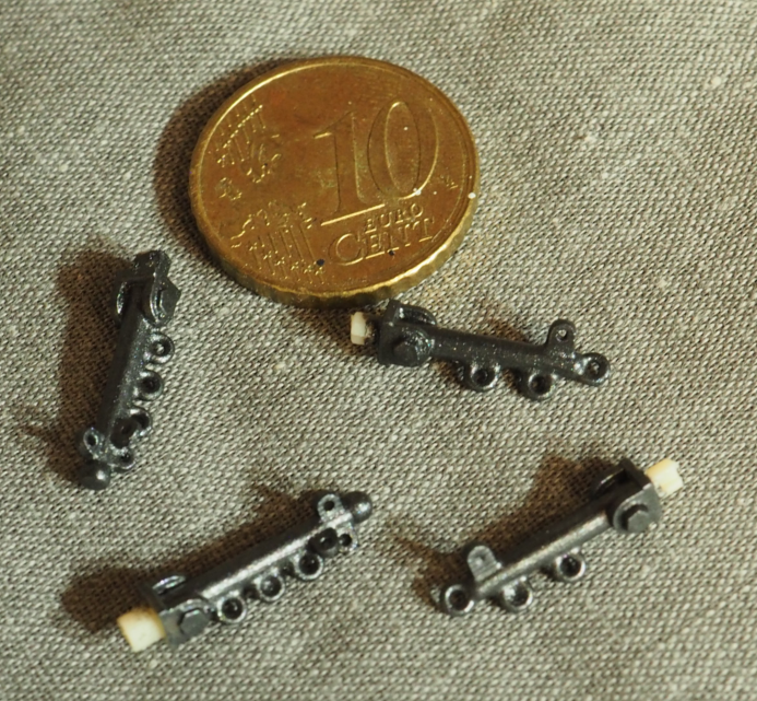
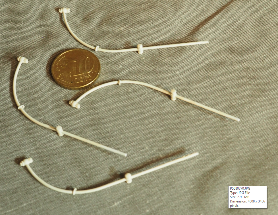
Bumpkins. Mostly because the revell one's are too simplistic, when you look at the real thing you realise the lugs are orientated to their respective tie points.
Davits. These are made using 1mm brass wire, I found the kit parts too chunky. I'm working on the philosophy that, if I reduce everything I can to be more in scale, there will be a greater sense of how large the ship is and how enormous are things like the lower yards
jackstays on the main and mizzen masts. 0.2mm brass wire running through miniscule brackets. I've used much the same approach on all the yards.
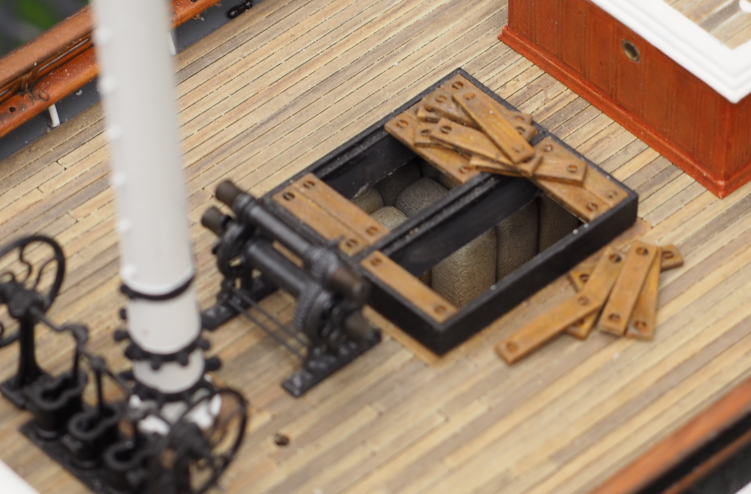
A random shot of the wool bales in the main hold. The plan is to, in due course, rig one being lowered into the hold via a hoist .
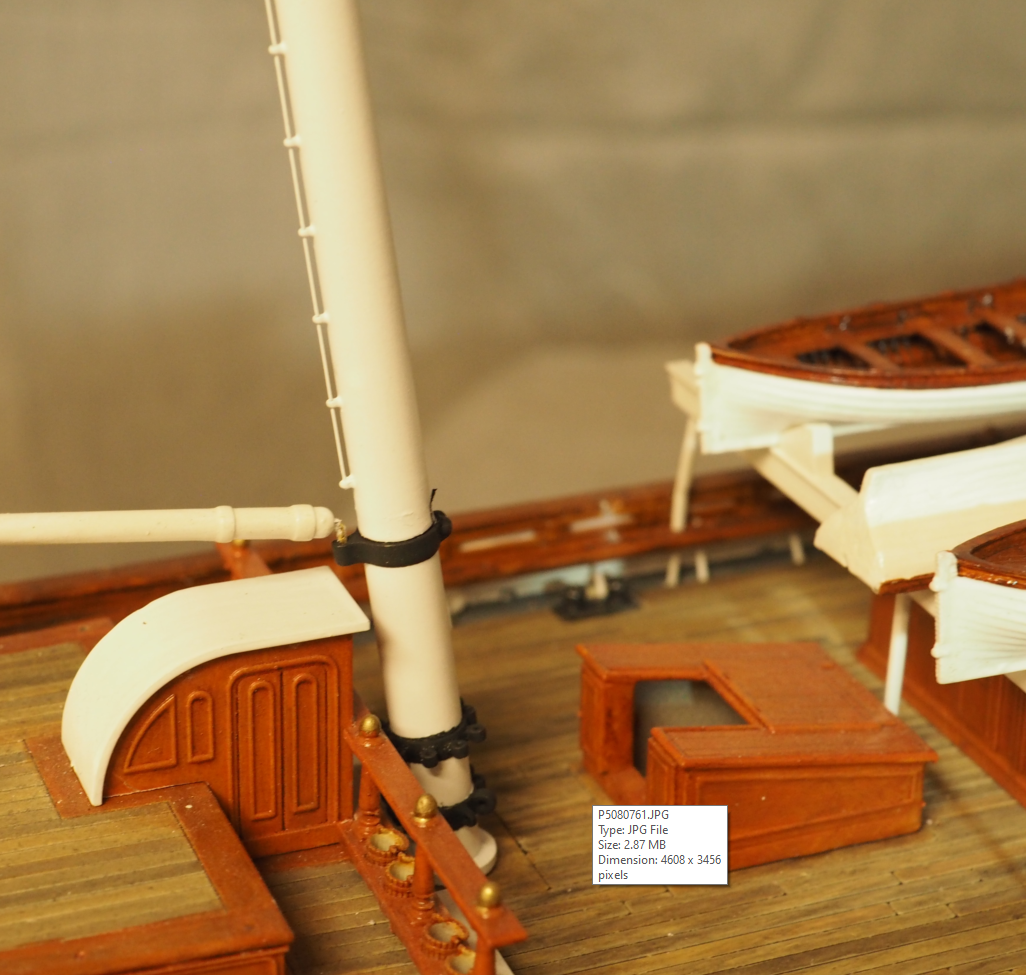
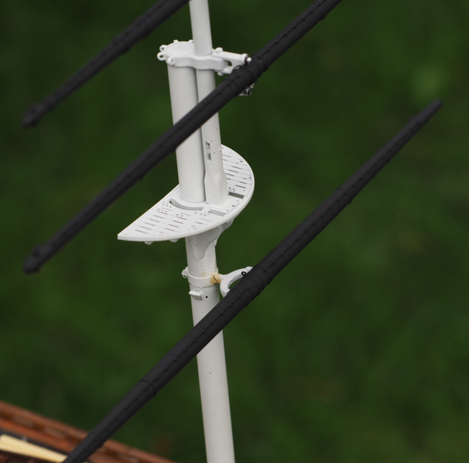
A shot showing the re-profiled foredeck and more imposing capstan, as I don't think I ever showed that in situ. I have work to do on the fore rails, one of many outstanding jobs.
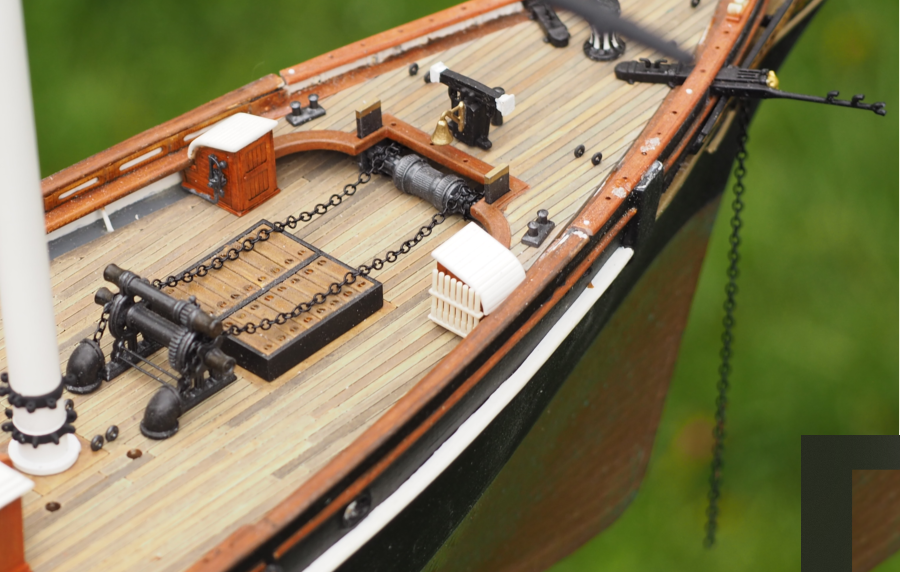
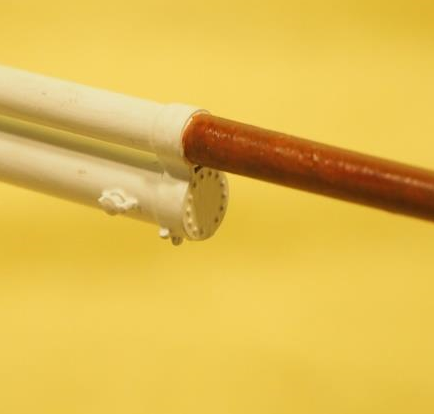
See the crack in the crane below? If you look very carefully, you'll see a tiny pinhole in the centre of the crane, this is where a brass rod runs through both crane and mast as the crane breaks so easily. Consequently it doesn't matter that it got broken, the yard is supported by the pin. The yellow stain is some super phatic glue, I'll cover it up when I finish the paintwork. I've used this method in quite a few places. Resin is good, but resin stiffened by CF or brass rod is better.
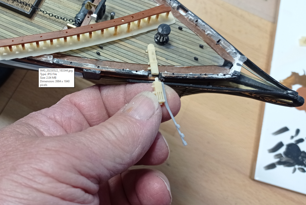
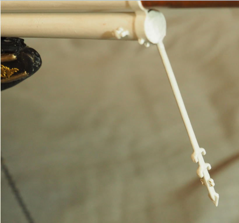
Here's a case in point: this dolphin striker is made as two almost mirrored halves, glued together with a 0.5mm brass rod in the middle. The overall diameter is 1mm and less chunky than revell. I found it impossible to print a 'tube' of these dimensions, but two halves was okay - you just have to have the lightest imaginable touch when handling the prints, until everything is glued up. (I was very glad to have some acetone to hand when doing this - I needed to 'roll' the parts between my fingers to get a nice tight joint, using CA glue, and of course managed to well and truly glue my fingers together in the process).
As ever, 3D is great for adding micro-detail. While I haven't yet started to count them, I do like to add rivets every now and then 🤪
So, that more or less brings me up to date. There's not much 'making' left to do now, it's mostly small fiddly bits and blocks, but there is still a lot of finalising / finishing off and then phase 2, the rigging. I found it very necessary to make more or less everything before I could confidently screw or glue things in place. Re' rigging, I suspect that will be a long job so I might pace myself and start another model to avoid boredom.
-
I’d endorse the Kevin Kennedy videos. He gets to the point and explains/demonstrates things very well. I also use the F360 community forum from time to time, most people are helpful. The downside of vids is that it’s harder to skim through - I sometimes play them at x2 speed, which helps - and there’s a fair bit of poor quality rubbish out there.
- thibaultron and mtaylor
-
2
-
Hi Allan (and anyone else looking to dip in a toe), this is what worked for me: https://diyodemag.com/education/exploring_3d_part_1_beginners_guide_to_fusion_360. If you work through the set of 6 tutorials you will learn all the essentials.
-
Pricey stuff, here in the uk. I guess I’m also missing the obvious - it’s probably flaking because the Vallejo primer is water-based, whereas, since these are metal parts, if I just used normal car body primer it should stick just fine. Or the little humbrol spray cans, which I sometimes use anyway for convenience.
- Canute, mtaylor, thibaultron and 1 other
-
4
-
Very tidy paintwork, you’re making me itchy to get back to the Victory. Yours is the first time I’ve really noticed the front two gunports left closed, I like that. I don’t think I’ve yet opened them on my second hull, might keep it that way. And those chains do look good, don’t they.
-
Interesting discussion. A few months ago I made railings for a model out of 0.5mm steel wire. I can't remember if I primed before painting white but in time the paint flaked off. What products or methods work best here?
- thibaultron, mtaylor and Canute
-
3
-
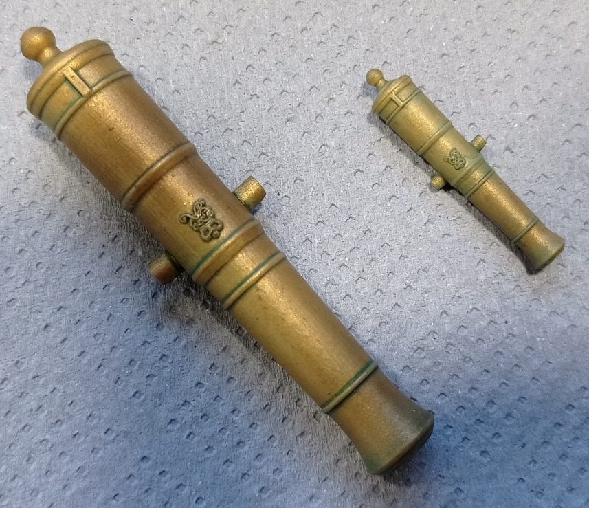
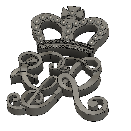
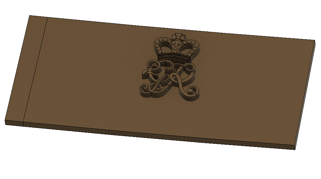
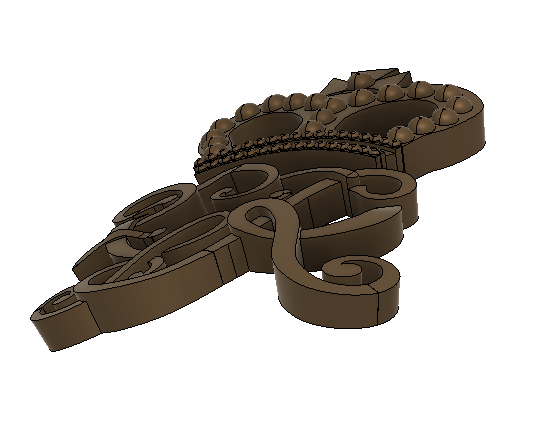
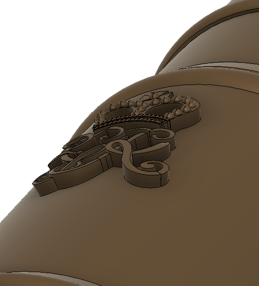
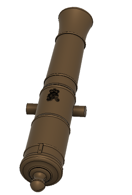
So... I've run a test print, and indulged in a bit of colouring. These are 32lb-ers at 1:48 and 1:96. Druxey is right, the cypher stands too proud. It's lovely, but not right. At 1:48 you can clearly make out that it's George II, but if you didn't know the letters are interwoven I doubt you'd spot it. At 1:96, you can just see that it has a cypher but it could be for Genghis Khan as much as King George.
Consequently I'm reducing the height by 50% and embossing as per PietFriet. That should make it a little quicker to get through a set.
-
Just to play devils advocate - I know what you mean about delamination of filament-printed parts but this is all about (high) temperatures. If you get the settings and environment right, the fusion will be good. I don't know what the composition or properties are of the mortar/concrete mix used for 'printing' but I imagine it's a cold pour and you probably have a wider temperature opportunity. There might be other problems, there usually area! For context, over the years I've worked on many an old and not so old brick-built building and there have been a good few instances of doing a job on the brickwork and finding I could literally lift a course of bricks off the (de-bonded) mortar. The thing being that for a two storey, double skinned house, this hasn't really mattered a jot. There's enough integrity overall to keep the building together, it's not going to fall apart. I suspect the same kind of thing will be true for 'printed' properties; at two or three storeys, and with a bit of re-bar every so often, it'll be fine. I'm not so sure I'd want to commission a printed tower block, but I doubt anyone is going to stick their neck out tat far anyway.
The finish is an aesthetic issue - some people will love it, others loathe it. If you don't like the 'cake filling' finish I guess you can render it.
Either way, I suspect it'll become commonplace within 10 or 15 years. Here in the UK we have a housing crisis: there aren't enough properties and they cost too much. It takes years and years for developers to build new estates, and this tech could be a game-changer.
My reservation is different - it's that I cannot for the life of me understand why we are still building houses from bricks, concrete, mortar etc, that are so expensive to build and difficult to modify in subsequent years.
- mtaylor and thibaultron
-
2
-
I set the height at 20mm full size, aimed at about 0.2mm at 1:96, for the same reason. To be honest I think the degree of detail I've added is probably a waste of time and effort, but, that said, I did some very, very fine detail scroll work on the HMS Victory stern and was surprised that it was both visible and, to my eye, looked worthwhile. I'm not certain now but think I was starting to work to 0.1mm level changes. Anyway, I'll review once I do a print session and, unless it really does show at scale, I'll shift to embossing, not least because that is such a quick and easy method. Lofting takes hours.
- PietFriet, druxey, thibaultron and 2 others
-
5
-
44 minutes ago, PietFriet said:
You can use the Emboss tool to project a sketch directly on a curved surface.
PietFriet, thanks, I never noticed that feature (note to self, to spend some more time on study). That would give a flat topped but properly wrapped cypher - is there another or better way to create the interwoven letters within F360?
- druxey, thibaultron, mtaylor and 1 other
-
4
-
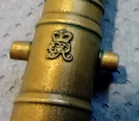
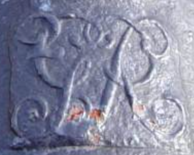
2 minutes ago, druxey said:
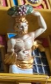
Beautifully presented, but I find it looks a little too high or deep. Can this be adjusted (see photo of the real thing)?
Yes, it can easily have the height reduced and the profiles made more true to casting reality - rounded edges, a curved top - but I fear at even 1:48 it would end up looking like a smudge, let alone any smaller scale. Right now we are having a very cold snap (or a slightly cold day for you north americans and canadians) but once the weather warms up and I can print, I'll do some sampling.
-
1 hour ago, Snug Harbor Johnny said:
They've just tested a rocket engine that was 80% 3D printed ... not sure if I'd want a ride on that.
I think '3D Printed' is just a logical extension of CNC production techniques. The computerised machine can't give things 'soul' the way a craftsman can, but 99.99999% of the time it can do it more accurately, reliably and efficiently. I think I'd feel more comfortable every time sat in a vehicle built by robots than humans - provided the design and programming are good, it's much less likely to be a 'friday afternoon job', if anyone is familiar with that expression! The materials and kit people like me are using are just toys, industry is using some very exotic materials and processes that presumably allow for much better quality control than in years gone by. What springs to mind is when I worked in shipbuilding: I could lay down as reasonable a weld as anyone but every now and then it might not be so good. In contrast, the submerged arc machine did perfect welds all day every day!
-
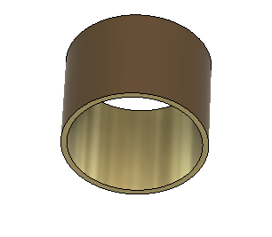
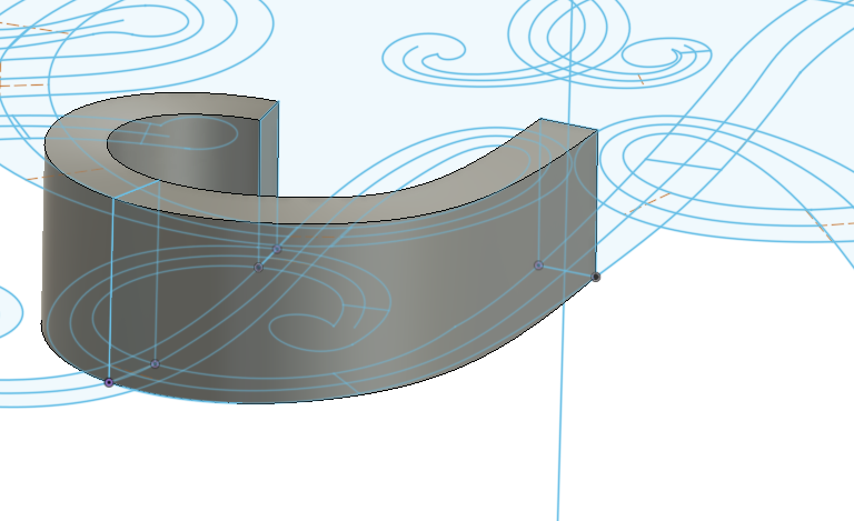
A bunch of us are creating STL's of a range of English cannons, a group project led by Allan. While the barrels are simple to model in CAD programmes, the cyphers take a bit more work and I agreed to share the way I did this one.
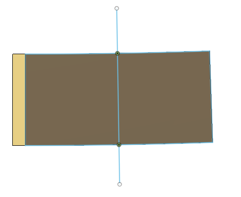
First, a bit of preamble: I work entirely in Fusion 360. The method I'm going to describe is undoubtedly not the only way even in F360 so feel free to chip in. I played around with the surfacing mode first but that way led to madness! Extruding the shape from a 2D drawing is very straightforward in F360 but left me with two issues; it doesn't properly wrap to the cannon barrel i.e. the edges would be uniformly vertical when they should follow the curve, and it doesn't allow the interweaving of the letters. So what I did was use the 'sheetmetal' function, so that I could correctly wrap, and lofting to get the interweaving. It goes like this;
Step 1: create a dummy barrel section. It needed to be hollow in order to be 'sheetmetal'. I use a thickness of 20mm but any thickness will be okay. This dummy section gets 'discarded' later
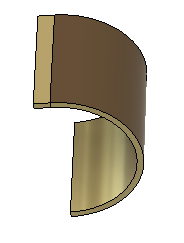
Step 2: Cut away half vertically
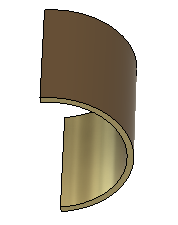
Step 3: add a flat flange in order to unfold
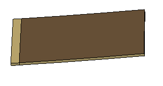
step 4: convert to sheetmetal and unfold. this allows me to create the cypher in the flat, and wrap it at the end
step 5: create a centreline sketch. I form the cypher 90 degrees off it's correct position, so that it doesn't sit astride the split/flange. If it sat astride, I'd have to made it in two halves. The important thing here is that this centreline is not vertical, but is set to the correct angle in the flat
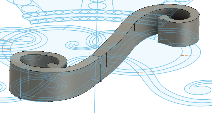
step 6a: position the cypher sketch on the centreline
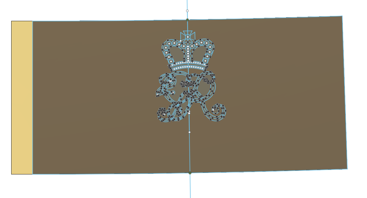
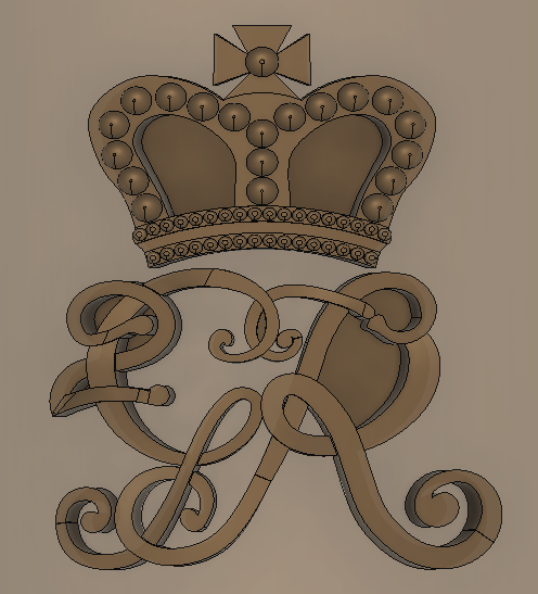
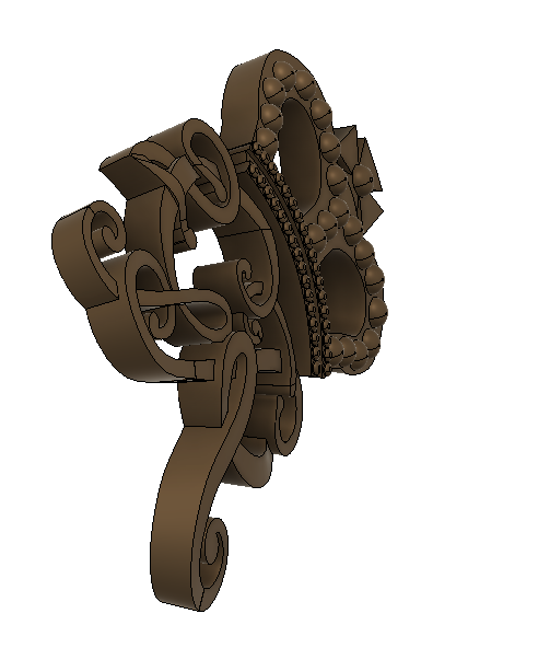
step 6b: an explanation of the cypher sketch. I'm making this in two parts - the crown, and the lettering. For the crown I simply extrude aspects to different heights in order to create the 3D relief. For the lettering, I create section profiles at different points in each letter and then loft the sections. This creates the sweeping under and over effect. The placing of the section profiles is entirely subjective and a bit of trial and error is needed. The centrelines through each letter are essential; the outer lines are only a rough guide and don't really dictate the finished shape.
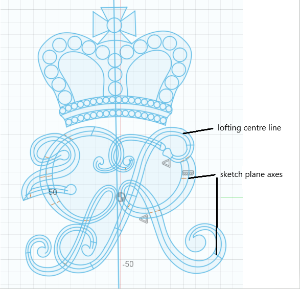
step 7: create planes at at angle (90 degrees) and section profiles
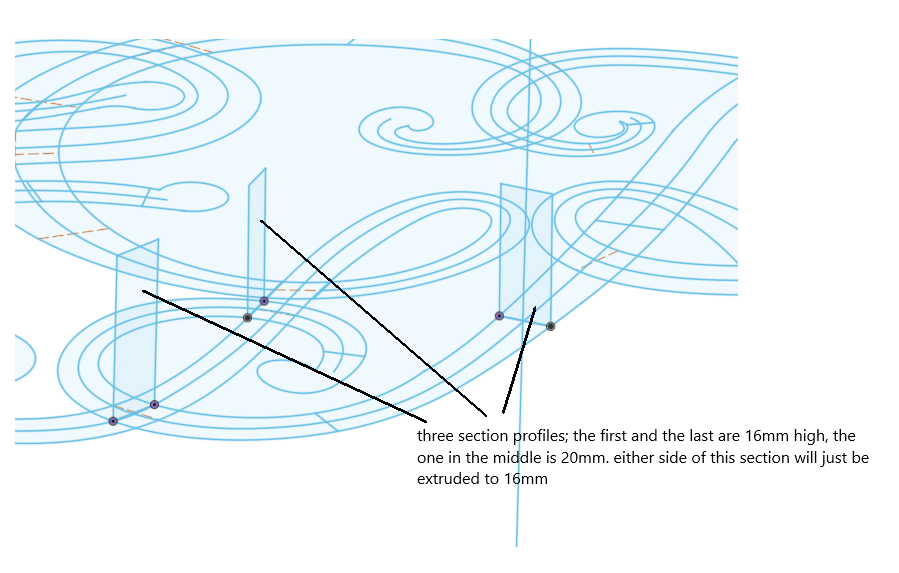
step 8: loft through these sections
step 9: extrude either side, and that's the first part done.
step 10: repeat that process for all remaining parts of the lettering. A point of detail here is that lofting centrelines can't 'loop' so you have to break those sections into segments. This requires a lot of planes and section sketches, roughly 30 in this case. I worked to this photo to more or less replicate the interweaving (and have just noticed a little mistake on the 'R')
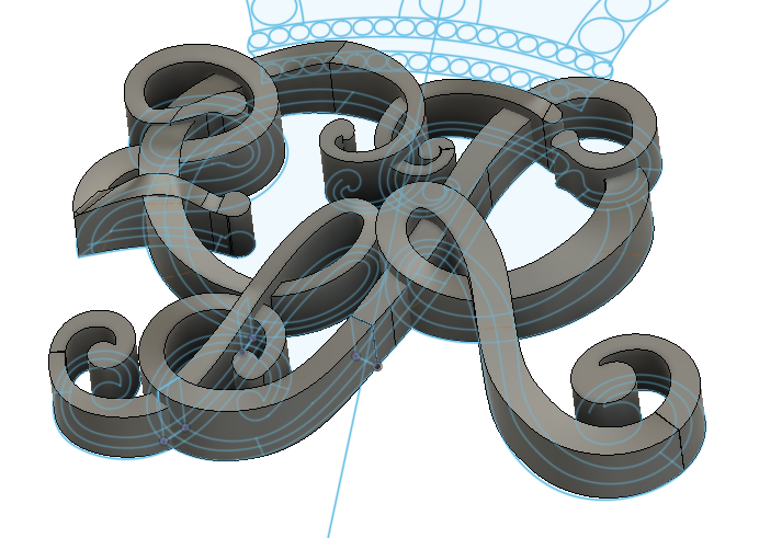
step 11: make the crown via straightforward extrusion
step 12: combine (join) the crown and lettering to the unfolded dummy cannon section
step 13: refold the section
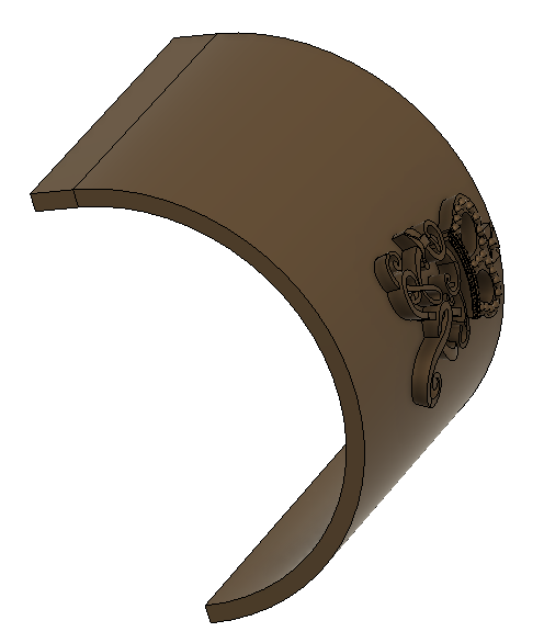
step 14: cut away the flange and dummy cannon section
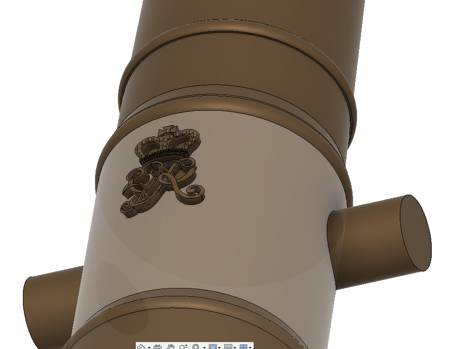
step 15: rotate the cypher parts through 90 degrees
step 16: combine with the cannon barrel and we're finished
I hope that helps, happy to discuss and learn a better way!
-
I'd love to see the finished product. I know of a bridge being 3D 'printed' in Amsterdam, and I'm sure this kind of thing will become commonplace in years to come.
- mtaylor and thibaultron
-
2
-
That vaseline tip is going to come in handy. As the accolades and plaudits reflect, your painting is simply jaw-dropping. As a side project I've just built a WW2 bomber straight out of the box and my pilots face STILL, despite all the wisdom and advice on forums like this, looks like a pink blob. I'm sure everyone reading knows exactly what I mean. Meanwhile, you're doing flesh tones and shading on a piece this small? It's like looking at the sistine chapel!
-
Great work Bill. Your experimentation with resin casting is very like the learning process with resin printing - 2 steps forward, 1 back, but bit by bit you figure it out.
-
This is one very intriguing project Ian - like some others, the arduino stuff goes way over my head but I can't wait to see the sea trials.
- Ian_Grant, Glen McGuire and mtaylor
-
3


Cutty Sark by Kevin-the-lubber - Revell - 1:96 - PLASTIC
in - Kit build logs for subjects built from 1851 - 1900
Posted
Ps.I’ll get in there first - the whisker booms are upside down. I can’t believe I’ve done that twice now. Remakes in process, easily corrected.