


Keith S
-
Posts
339 -
Joined
-
Last visited
Content Type
Profiles
Forums
Gallery
Events
Posts posted by Keith S
-
-
This model looks like a lot of fun. What an unusual vessel.
-
When I was glue-ing the keel pieces in my model I noticed it was easy to fit that particular piece incorrectly. Mine is also going to require slight correction.
-
He deliberately stopped working on the model when it got to the stage where it looked like a shipyard model- I gather that the shipwright or designer in the old days would prepare a model for the Navy, before building the actual ship, which had some basic details but not fully built. Matthew Betts says in his blog that he took his model to this level of completion because it was going to be displayed alongside an actual shipwright's model of Erebus from 1829.
I get the impression that when the model is returned to him, he intends to continue the model to a higher degree of completion. You can see on his blog that he's done a lot more research on parts that do not appear on his ship as she currently stands. I presume that's because he's got more he wants to do.
-
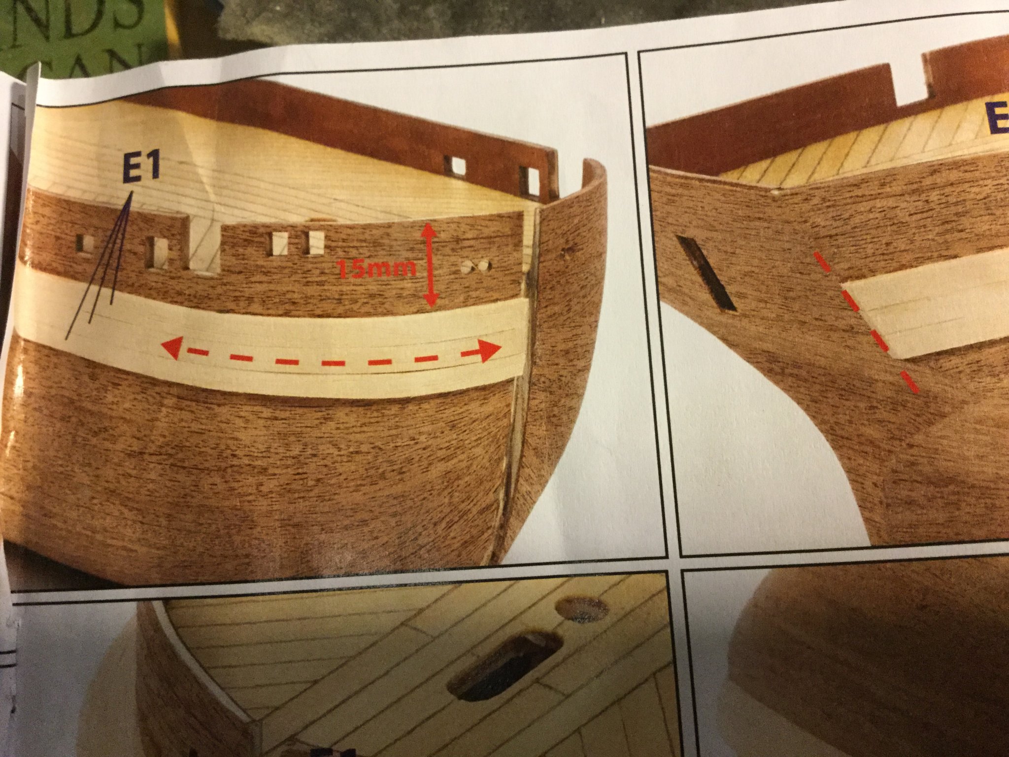
Hi Robert! Here is the measurement in the plans I am referring to. This "15mm" should be 20mm. You can tell by looking at the planks above it- they are 5mm wide and there are four of them. Like I said I emailed OCCRE and they acknowledged it's a typo. It doesn't make a lot of difference but I am always looking at my model compared to pictures of the model made by Matthew Betts and the shipyard drawings, and I spotted the error. I had to tear off my chock channels and do them over.

-
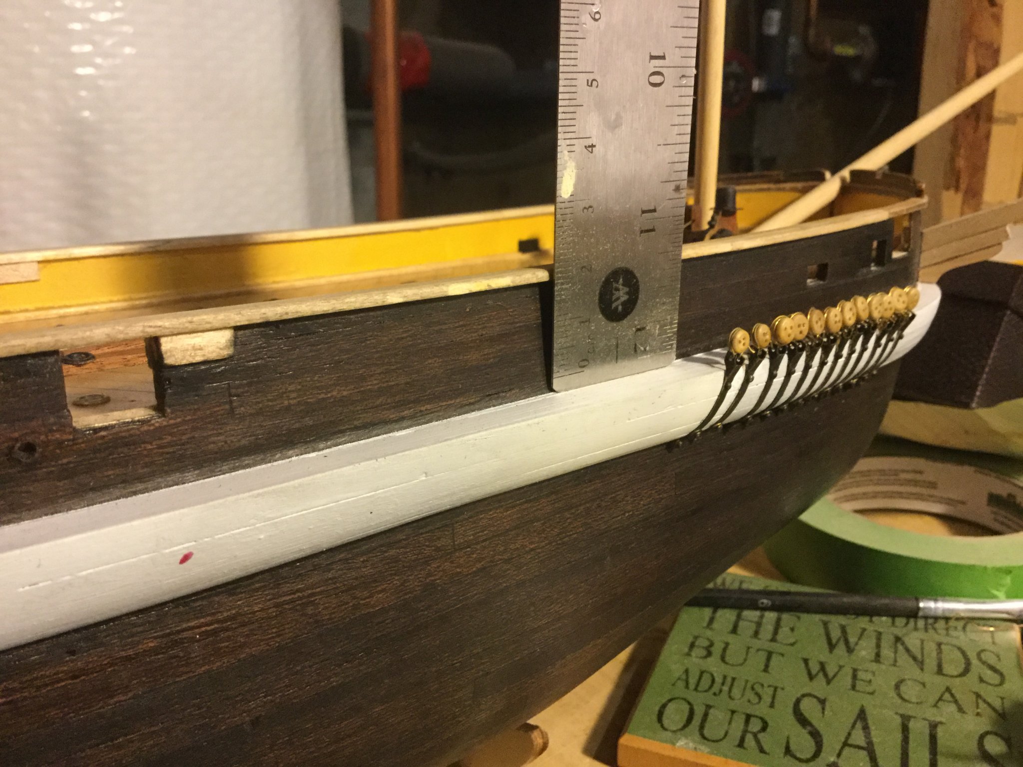
Here you go, Obvious Newbie, I took some pictures of the chainplates on my model and a link to the online store I purchased them from:
https://www.castyouranchorhobby.com/Category/Strop


- uncarina, Ryland Craze, gieb8688 and 2 others
-
 5
5
-
23 minutes ago, ObviousNewbie said:
Hi Keith, she looks great, splendid work. Could you shed some more light on the channels and deadeyes? What did you use? I'm building Terror as well, and this is one of the open questions I still had, as I4d like the channels to be black like yours.
Thnx in advance for your help!
I'd be happy to help! The deadeyes are attached to model chainplates. I did not like the use of brass wire to make them, so I ordered some from an online store in Canada called "Castyouranchor.com" I will provide a link to the specific product I used. They are quite long, but easy to snip to the right length and I think they are probably exactly what would have been on the real ship. I also attached them at their lower end just below the chock channel with the little "8" shaped brass bits from the kit. I will go downstairs and take pictures of these so it's more clear. I'll also show you what I mean about the measurement of the chock-channels themselves.
- Sea Hoss and ObviousNewbie
-
2
-
I wound up regretting that I had used cobbler's glue (contact cement) on mine. Every now and then, a board springs loose on mine. The "wood prep" solution I applied prior to staining seemed to loosen it up. It's not a tragedy but is somewhat annoying. I think you're better off with the PVA if I'm honest.
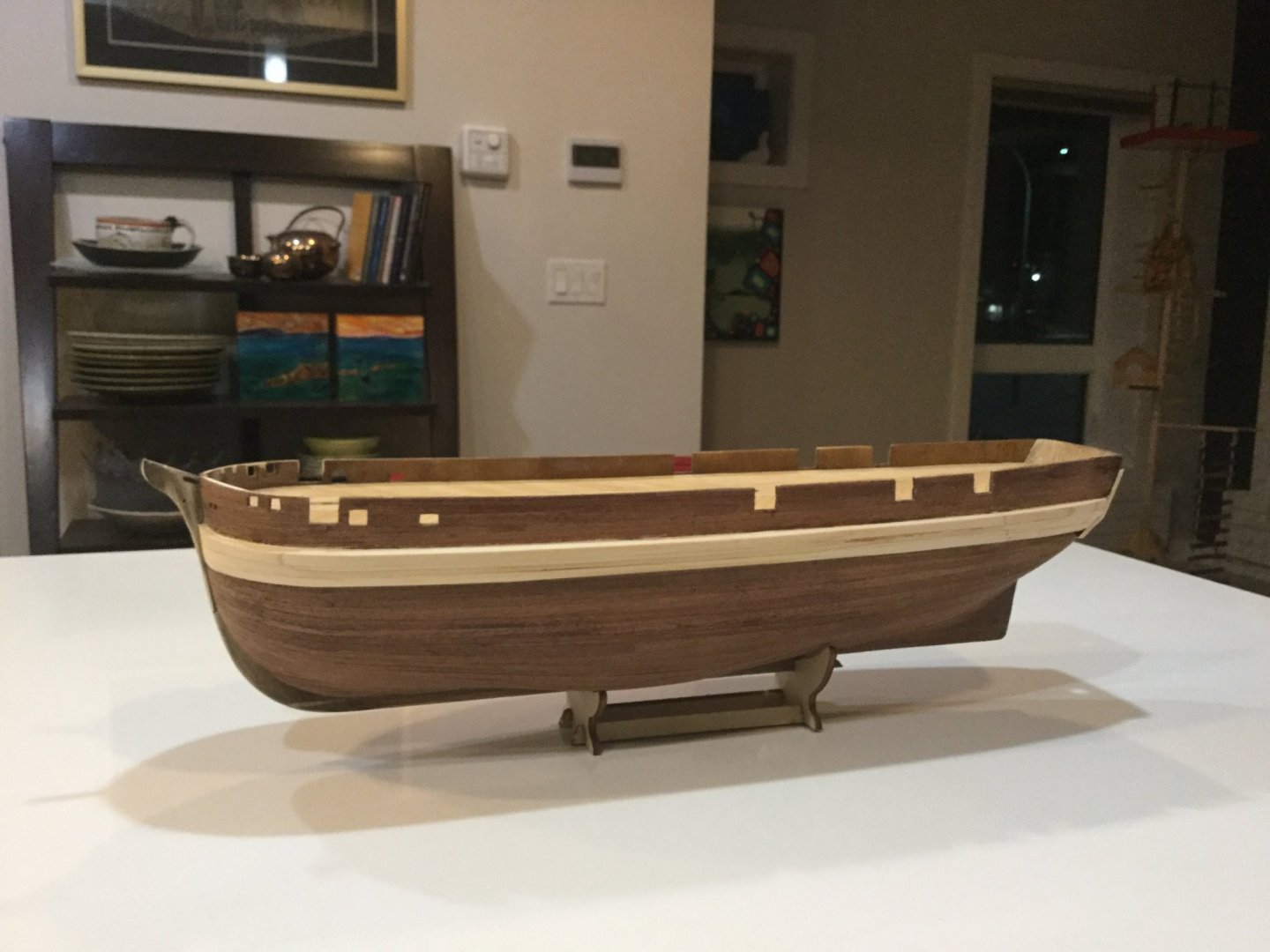
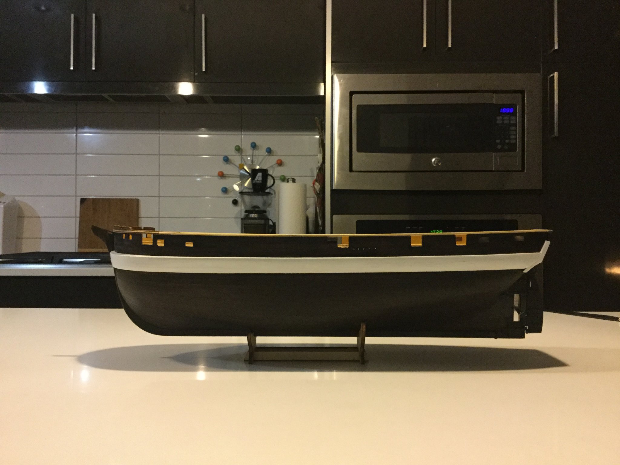
When you get to the stage where you are ready to mark out the location of the ice-chocks (the broad band of planking that looks like a bumper), consider placing it 5mm lower than the measurement depicted in the plans. If you look carefully at pictures of the completed model, you'll see a discrepancy. It's easy to spot if you look at the placement of the small metal panel beneath the first opening in the bulwark back from the bow. I wrote to OCCRE and they confirmed that the measurement in the instructions is a typo.
- Sea Hoss and ObviousNewbie
-
2
-
Novastorm You know it's interesting you should point that out, because I had wondered the same thing myself about stanchions. I've seen this model built by others where some representation stanchions have been added, but I am not sure if this is a correct detail. For guidance on any changes to the kit I might make, I am referring to the blog written by Matthew Betts, whose plans for his scratch-built model are credited in the kit literature as the basis for the kit. His model does not show any visible stanchion structures on the inner bulwarks either. For reference I checked out pictures online of the preserved Leda-class frigate HMS Trincomalee, and there are no visible bulwark stanchions on her either. I concluded that there must be inner as well as outer planking. If you check out Mr. Betts' blog this seems to be how he built his model - the stanchions or upper frame extensions are encapsulated within inner and outer planking. On the much smaller OCCRE model this is just plywood of course, which is one reason I painted it rather than leaving the natural wood colour.
One thing I did change because it looked right to me, is the upper beam of the catheads. I did not think that in real life this would simply have been bolted onto the bulwark planking. I consider it to be more likely that this beam penetrated the bulwark to be embedded in the deck and attached somehow to the ship's internal structure. I don't know if this is correct but to me it seems likely, even though I must admit there is no sign on either Mr. Betts' drawings not the Royal Navy archived ones that this was the case. Maybe someday it will show up in an underwater photograph of the real ship.
Bob, I did not seal the hull before staining, I rubbed the wood with minwax "wood conditioner" to help the stain penetrate, and just brushed on the stain. That's about three coats you see there. I am thinking of going over it with a coat of satin-finish spar varnish but haven't done that yet. The deck is finished with satin finish spar-varnish. Some guys weather their decks, but I didn't. I've noticed however that it's taking on a bit of a patina from constant handling and dropping things on it and wiping up drops of glue...
-
Ha ha, everybody gets Yellowknife and Whitehorse mixed up.. unless you've been to both of them, they are quite different. I spent some time in Whitehorse and became fascinated with a wreck in Lac Labarge, which is a big lake near Whitehorse. In fact, it was my first attempt at model ship-building. The wreck is a small sternwheeler called A.J. Goddard, and she lies intact on the lakebed in perfect condition except her wheelhouse, which floated away being light and wooden. She makes an interesting subject for a model because unlike larger sternwheelers, her engines are locomotive-type with Stevenson's valve-gear, which is easier to model because you can use train parts. I went so far as to build a cardboard mock-up of the hull before shelving the project until I learned more about live-steam boiler building. Some day I will pick it up again.
-
Thanks guys for taking the time to look at my model and the kind comments. Today I received word from my employer that as an "essential services" I will continue to work but am instructed to remain under quarantine when not on duty. I guess I will be getting a lot of modelling time now considering I can not drink or hang out with my friends. At least I still have a job, unlike a great many other pilots.
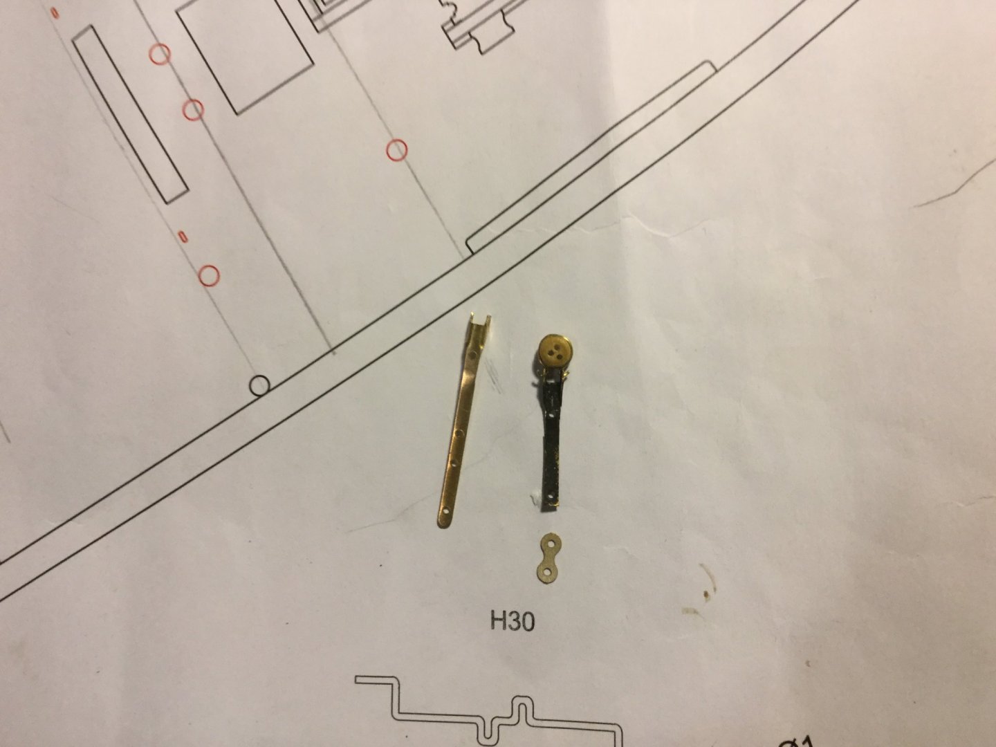
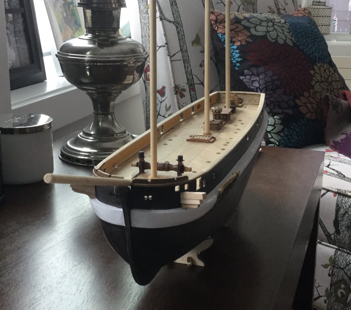
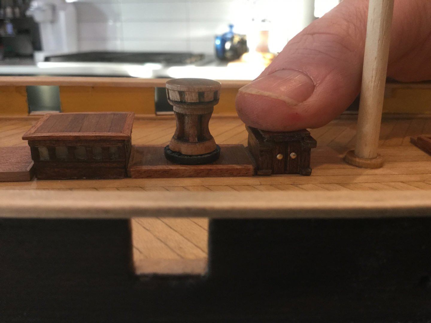
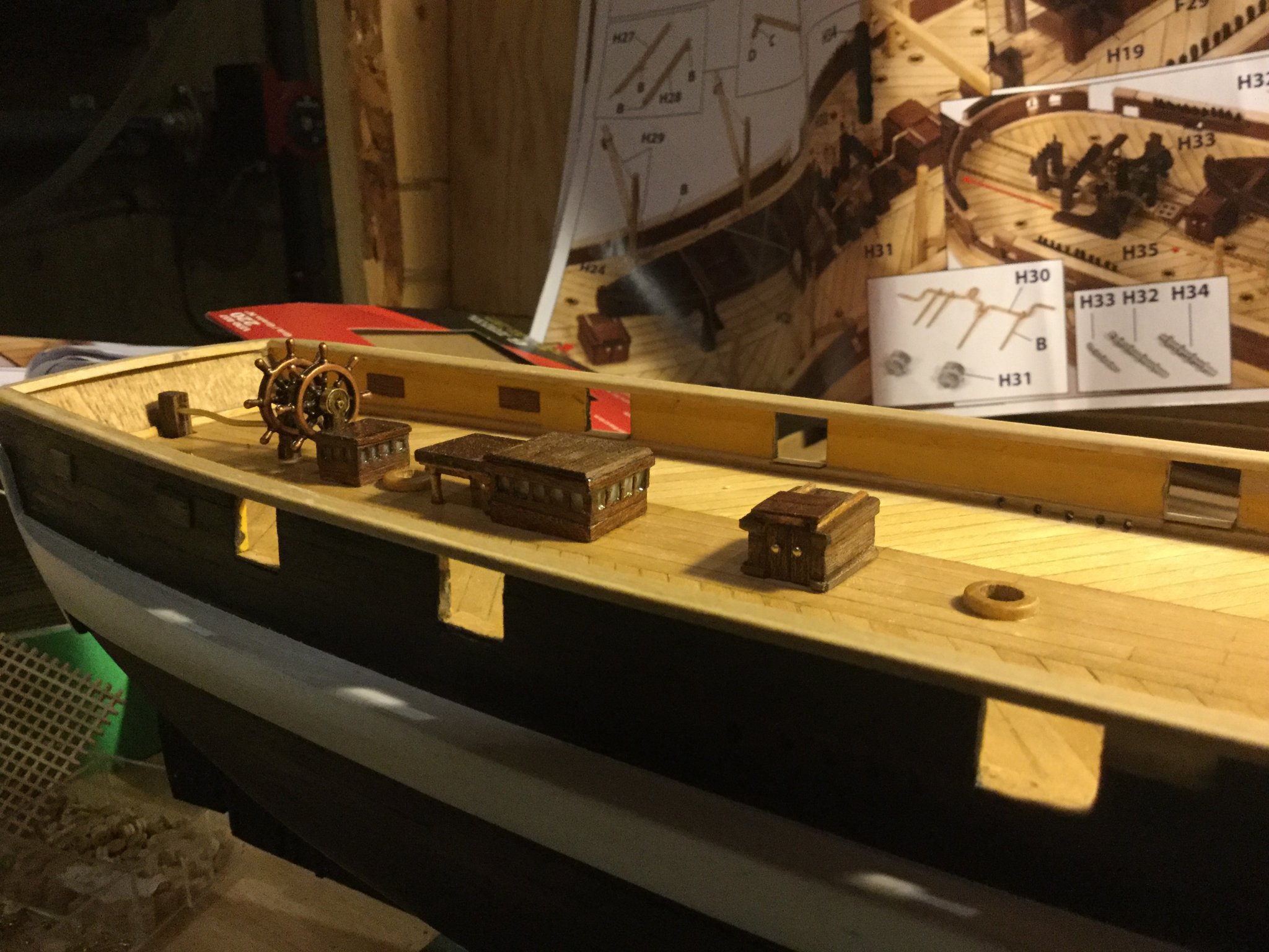
Lately I have been working on the ship's windlass. I am generally very impressed with the quality of the OCCRE kit, but there are many parts, for example the 8-spoked wheel, which are generic "ship parts" but are not exactly correct for this specific ship. If one were to use only the parts in the kit, one would have a very nice model of HMS Terror. However, it is always possible to improve any kit, and I have set about researching the real ship and doing what I can to make my model as much like the real one as possible. What makes this possible is the incredible wealth of information on Matthew Betts' blog, in which he generously makes available a great deal of the painstaking research he has done in this ship using Royal Navy archives.
I've modified the kit windlass to more closely resemble the one in the shipwright's drawings of HMS Erebus and HMS Terror. These ships during their lifespans were right at the beginning of the era during which iron came more into use in ship construction. The original windlasses were probably the big wooden kind with huge oak "knees" reinforcing the cheeks of the windlass. The most recent drawings of HMS Erebus from the early 1840s show that her windlass was modified or replaced with one that made use of iron rather than wood reinforcement. It is reasonable to assume that HMS Terror was similarly modified, as by this time the two ships were operating together most of the time, and there was a policy of commonality to reduce the number of spares required on an expedition.
I made this one by turning pieces of dowel in my dremel and assembling them on a toothpick for the "drum". The windlass "cheeks" were made by cutting the back half off the plywood kit peices and gluing them onto a piece of 1x6 mm Walnut stock with blackened pins to simulate the rivets on the real one. I made the big iron bitts on top out of bits of dowel and sheet brass, and the iron brace in front out of scraps of brass fret from the kit.
-
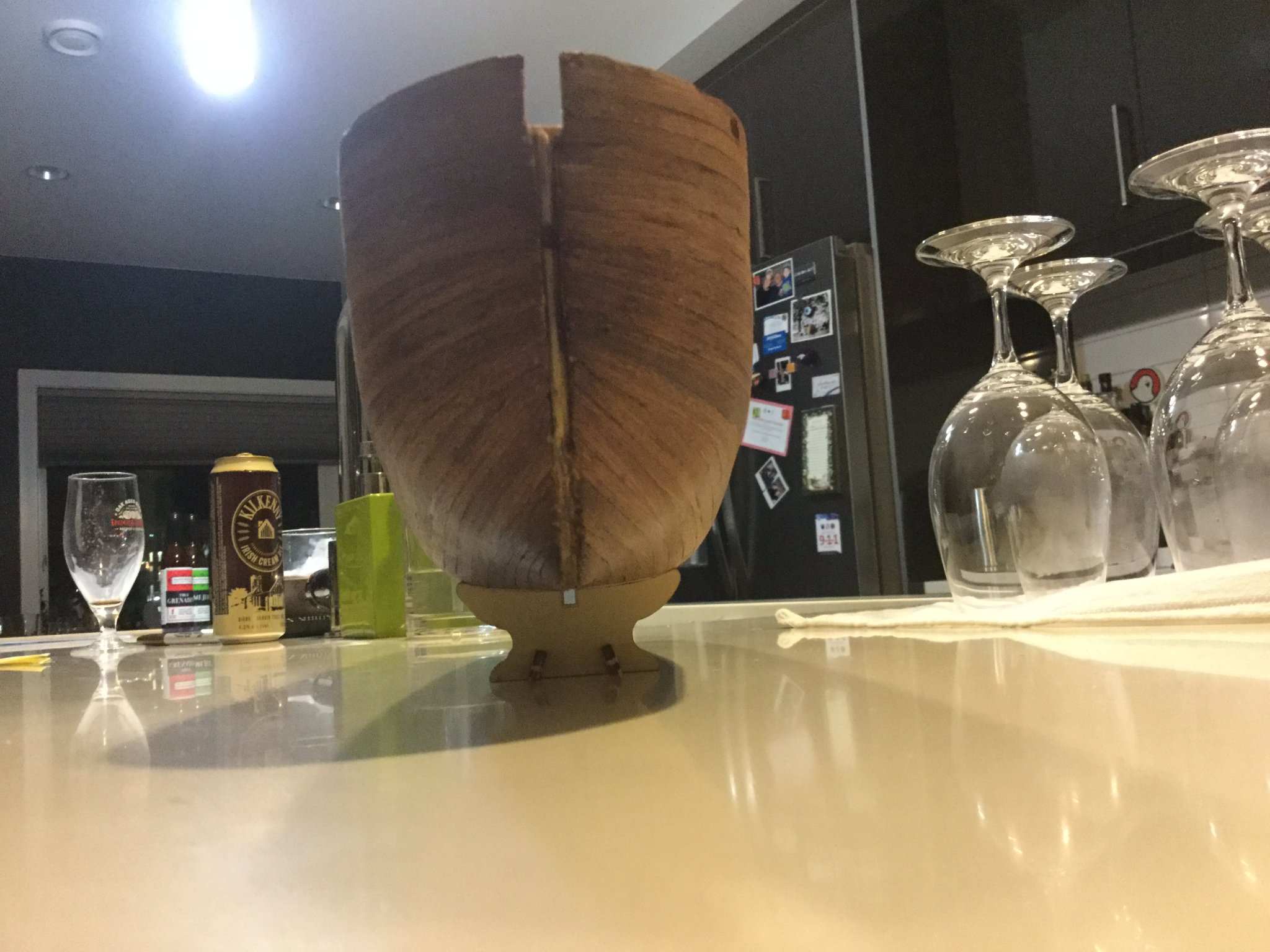
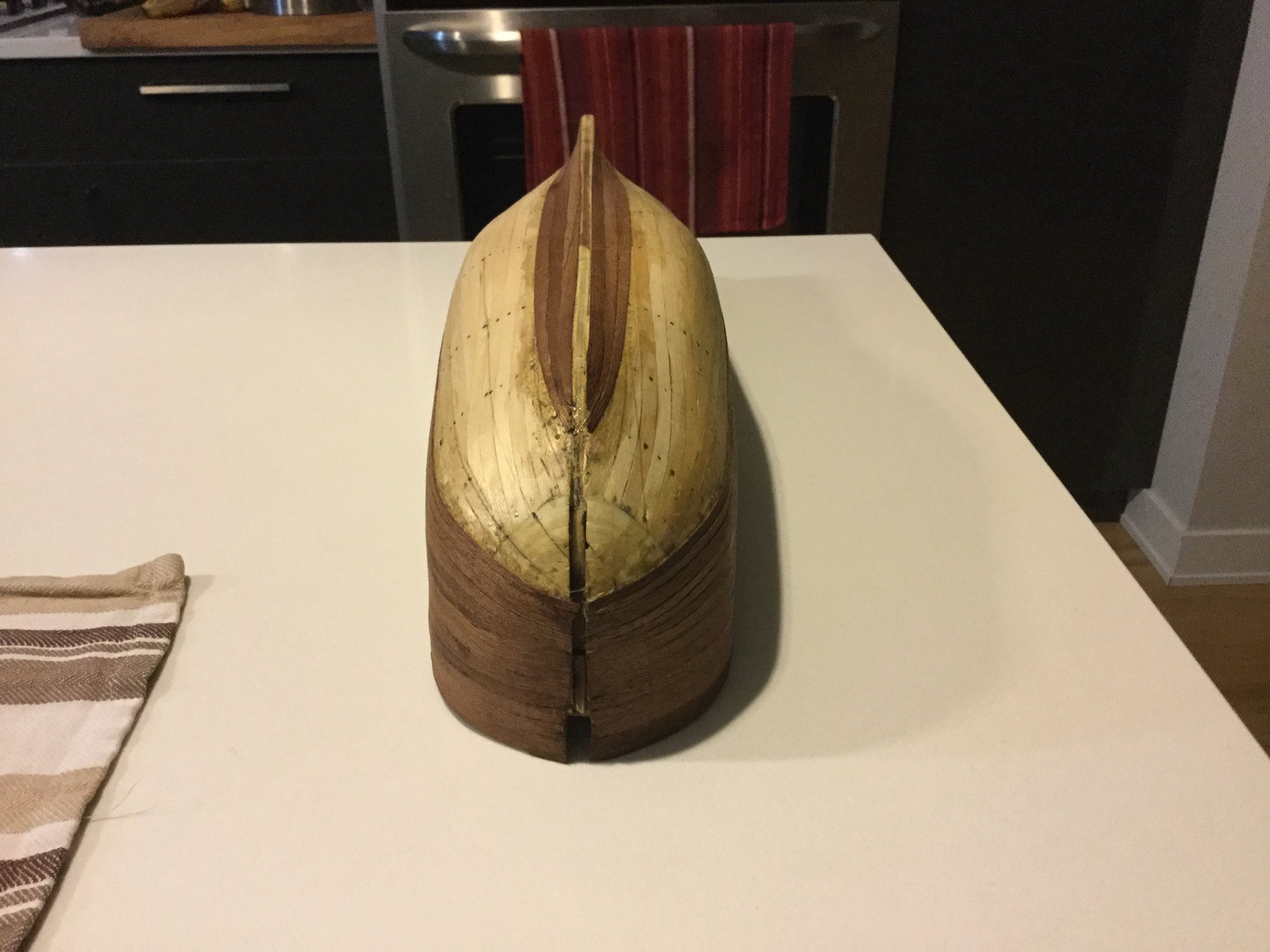
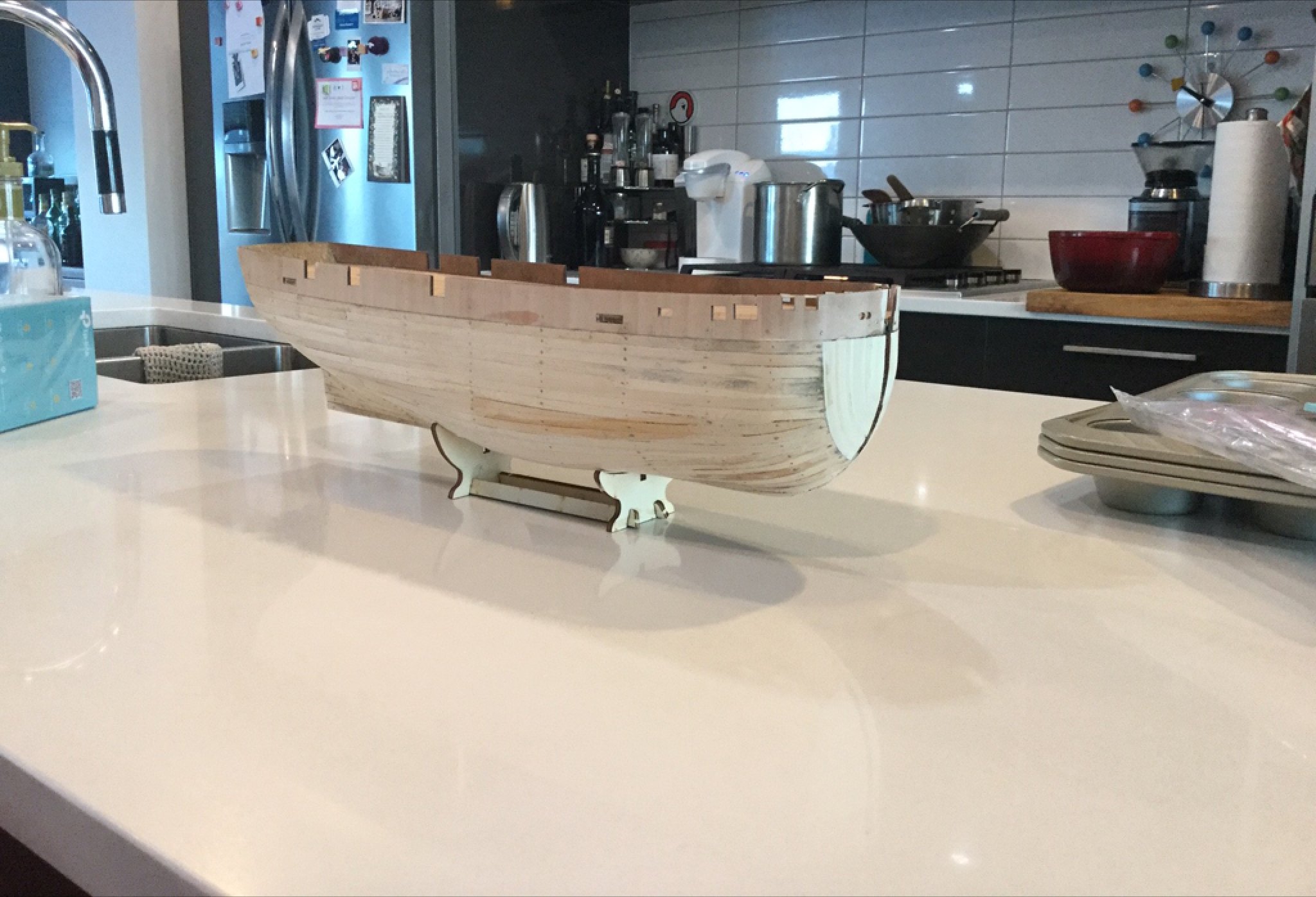
I don't think you're missing anything! My experience at this stage was the same: I could feel bumps that I couldn't see. I used a sanding block where possible and some other bits of round scrap with sandpaper glued to it on the convex parts at the rear of the hull. That first layer of wood is quite thick, so you can sand the heck out of it to make sure everything is smooth and the curves all run fair from bow to stern. It's a lot of work but if you miss a bump or a bulge, one day when the sun hits the model in just the right way you'll see it and it will drive you nuts. I think running your hands over it is the best way to see that the curves are fair.
If you have wood-filler, you may find you need some to fill in some gaps in the planking, but I would advise that you just sand and sand and sand first. In my experience if you overdo it with the filler you'll get a satisfactory surface before you have really finished shaping the hull. You can take off a lot of material on that first layer of planking without sanding through it!
Take what I say with a grain of salt though- I've inly built one of these things myself.
-
-
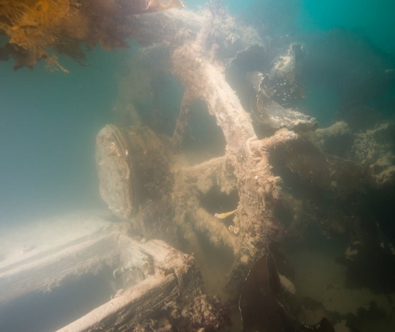
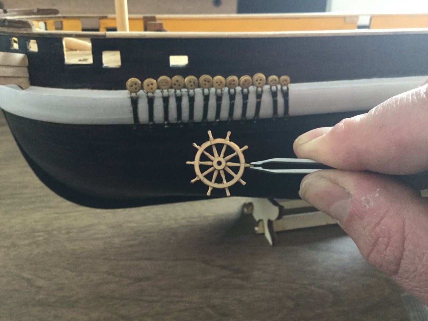
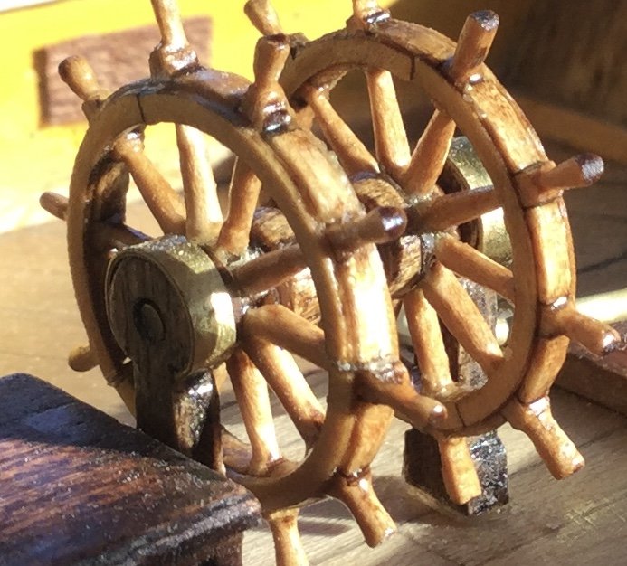
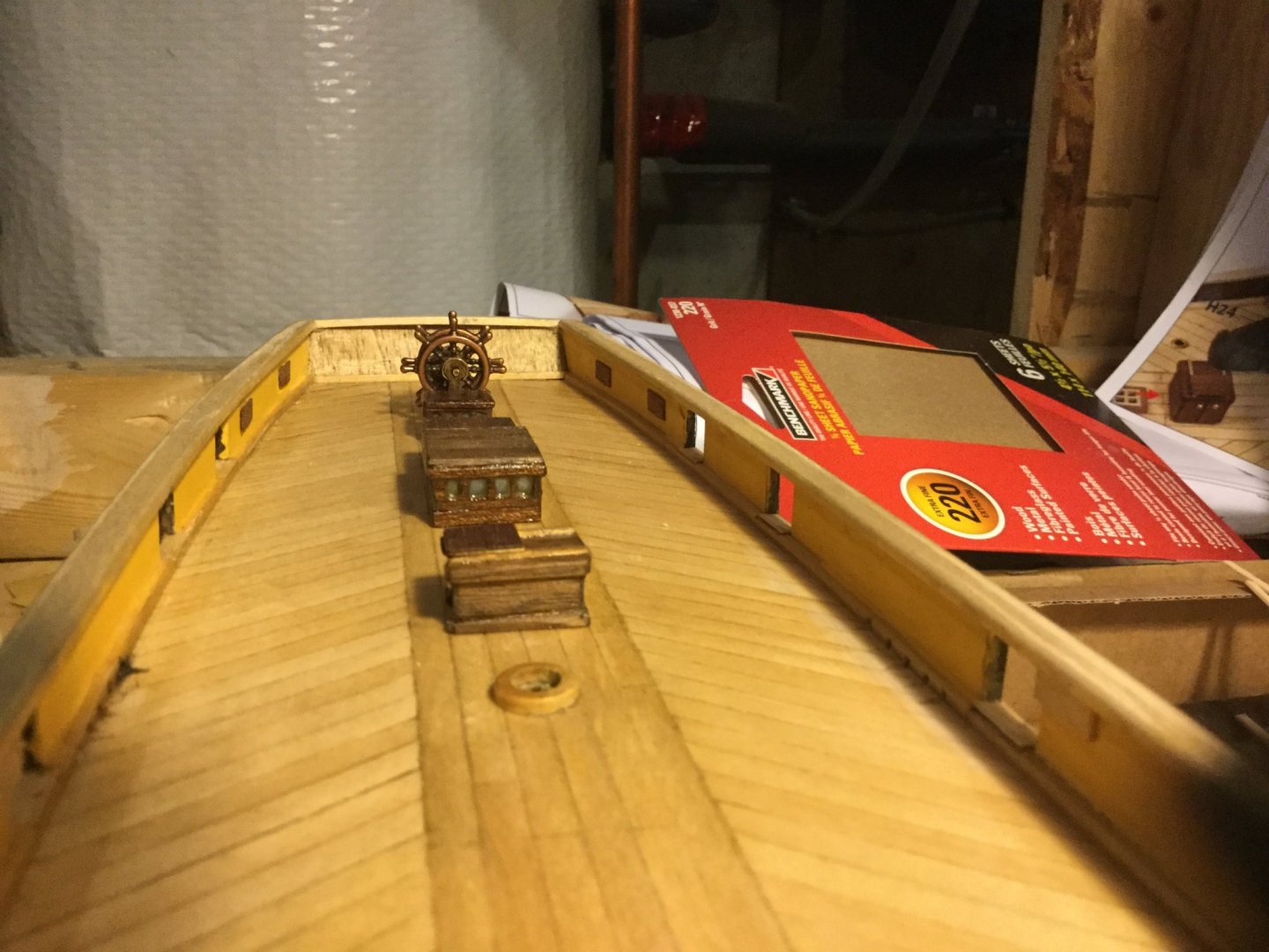
Here is where I decided I did not like the wheel supplied in the kit. The reason for this is that the real ship had a ten-spoked wheel and the one in the kit is eight-spoked. This would not have bothered me too much, except we now have actual photographs of the real ship's wheel as she lies today, and we can see she has a ten-spoked one! Luckily, I was able to find a mini-kit to build ten-spoked ship's wheels in precisely the same diameter as the kit one, from Syrenshipmodels. Now, my model has a more historically correct wheel. I am quite tolerant of educated guesses and compromises in models, but when we have a photograph of the real ship, I would like the model to match what we see in those photographs. Minus the seaweed of course.

- ObviousNewbie, catopower, JayCub and 7 others
-
10
-
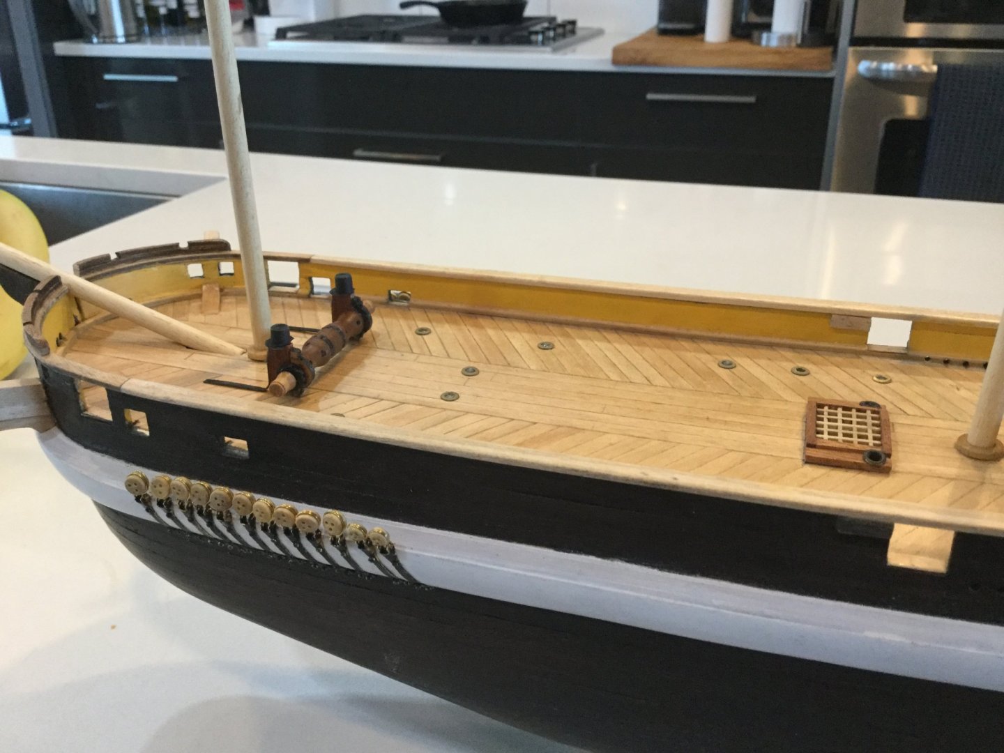
Here I have made a start on the chainplates for the foremast. Rather than build them up out of wire, I ordered some model chainplates from "Castyouranchor.com". They are very realistic, and I used very thin brass wire to fish the deadeyes onto them. I chemically blackened them and attached them using the brass eyes from the kit. I think they are a pretty realistic depiction of what the real thing may have looked like.
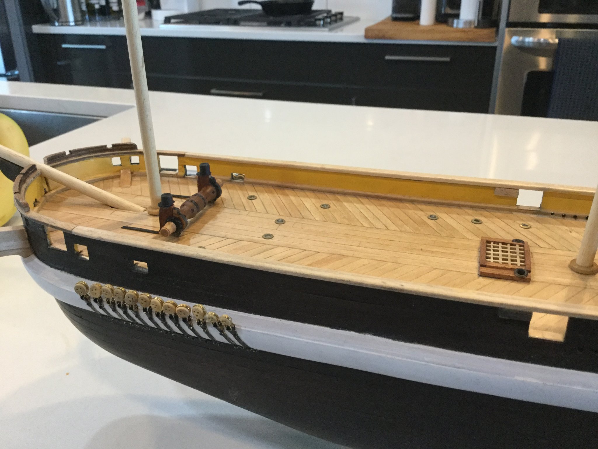
Also, here we can see I have made a start on the ship's "Preston Patent" deck illuminators. In the kit, these are depicted with little brass grommets. Fair enough, but a real "Preston Patent" illuminator is rather flat and flush with the deck. So, I used a small file to flatten each grommet, and then made a "lens" for each one by squeezing hot glue into the bottom until it domed out slightly on the deck side.
- NovaStorm, Haliburton, BobG and 3 others
-
6
-
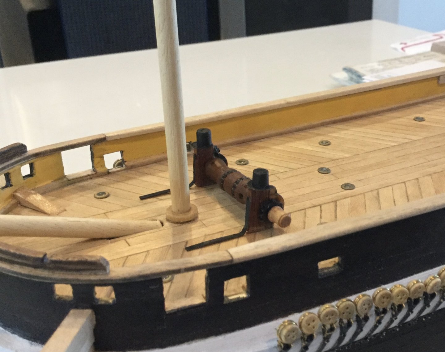
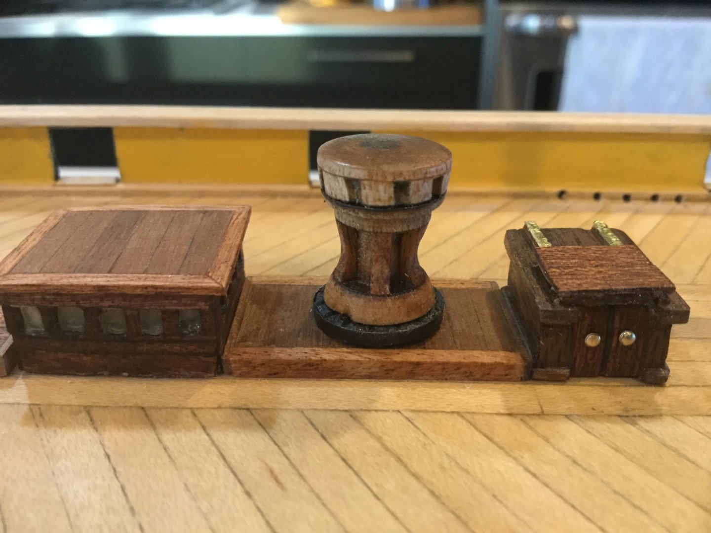
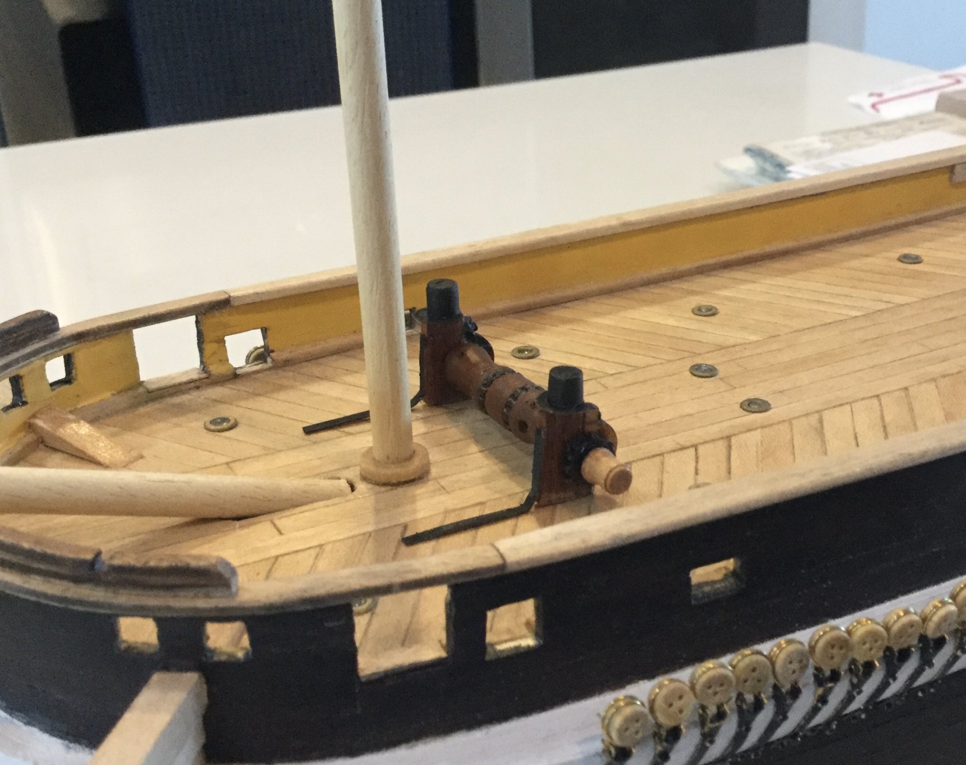
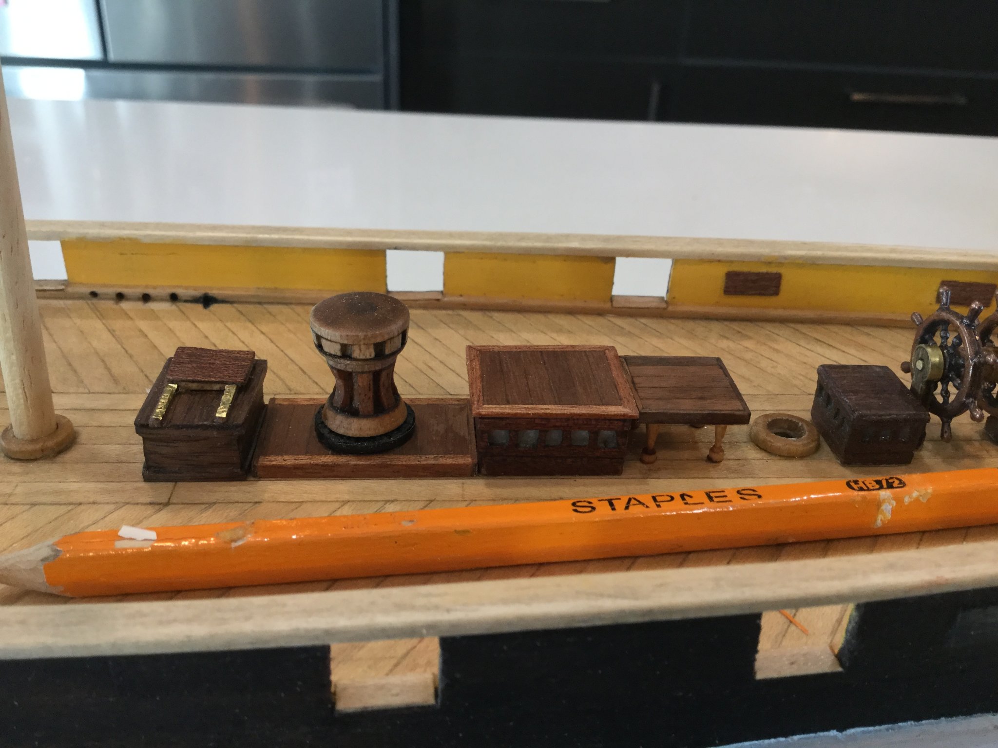
Here I have re-made the ship's capstan to better represent the Phillips' Patent capstan on the real ship. The one in the kit is quite small and lacks detail, so I made this new one using Matthew Betts' blog in which he describes the capstan and his excellent reproduction on his scratch-built model. Also, in these pictures you can see the aft companionway, which I cut down to a shorter height. Drawings of the ship show this companionway was shorter than the forward one, probably to provide clearance for the capstan bars.
I made the capstan by turning the pieces using my dremel tool.

- NovaStorm, Dean77, ObviousNewbie and 4 others
-
7
-
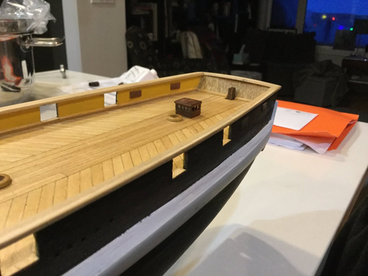
Here I have begun working on the upper works. I was not particularly impressed with the kit's depiction of the deck skylights. On the real ship, the skylights were flat-topped and glazed all around with small rectangular panes. On the kit, the individual panes are depicted with brass rods in a rectangular aperture. I tried to improve upon this by cutting individual panes into a piece of 4mm walnut strip, and backing it with very thin plastic, which I glued with thin CA to make it look frosted.

- catopower, GrandpaPhil, JayCub and 3 others
-
6
-
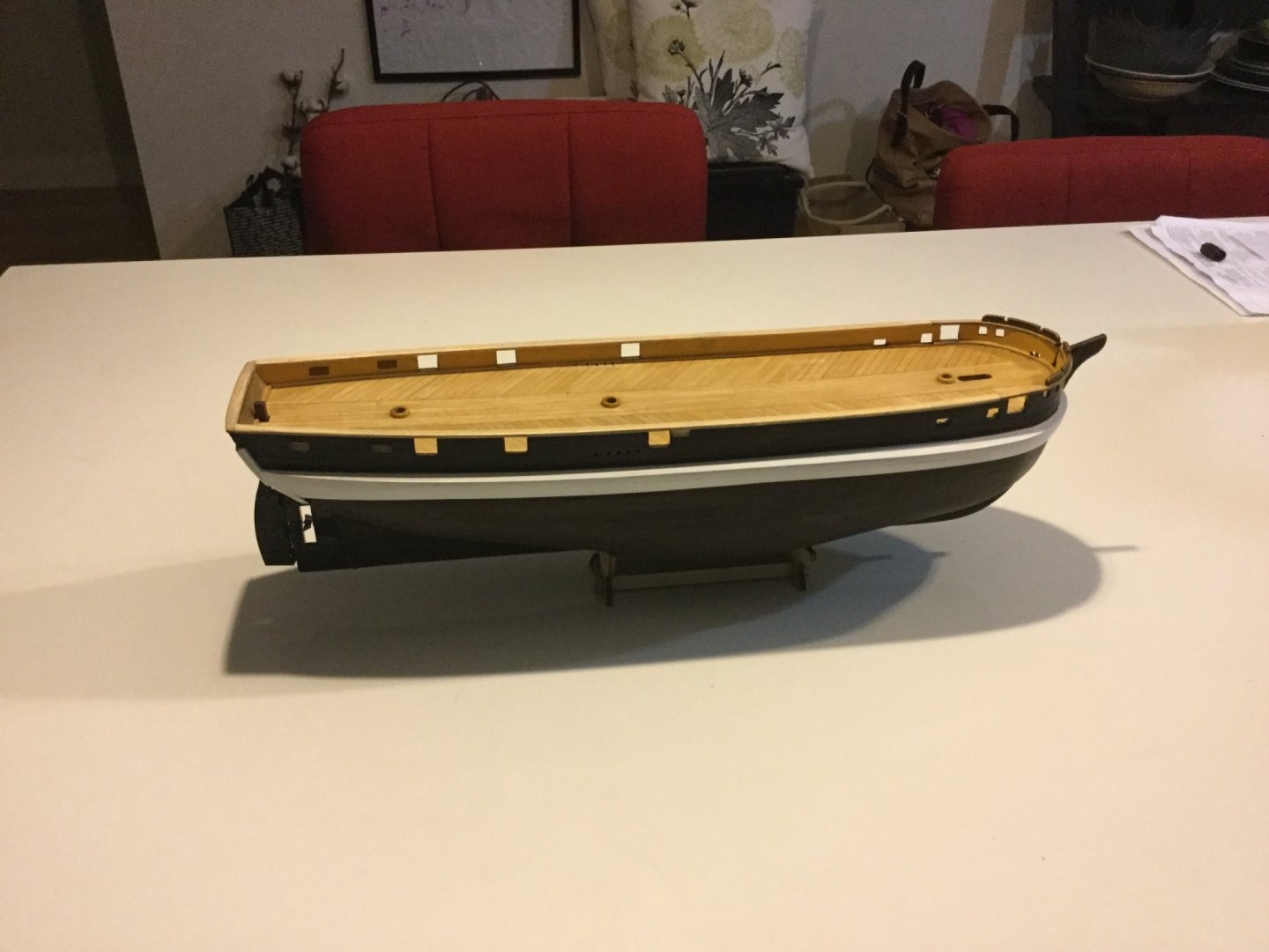
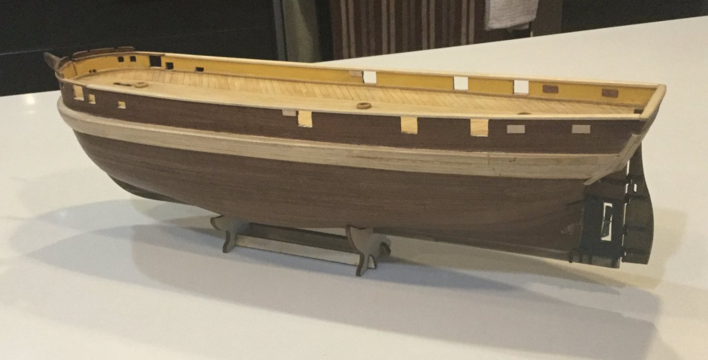
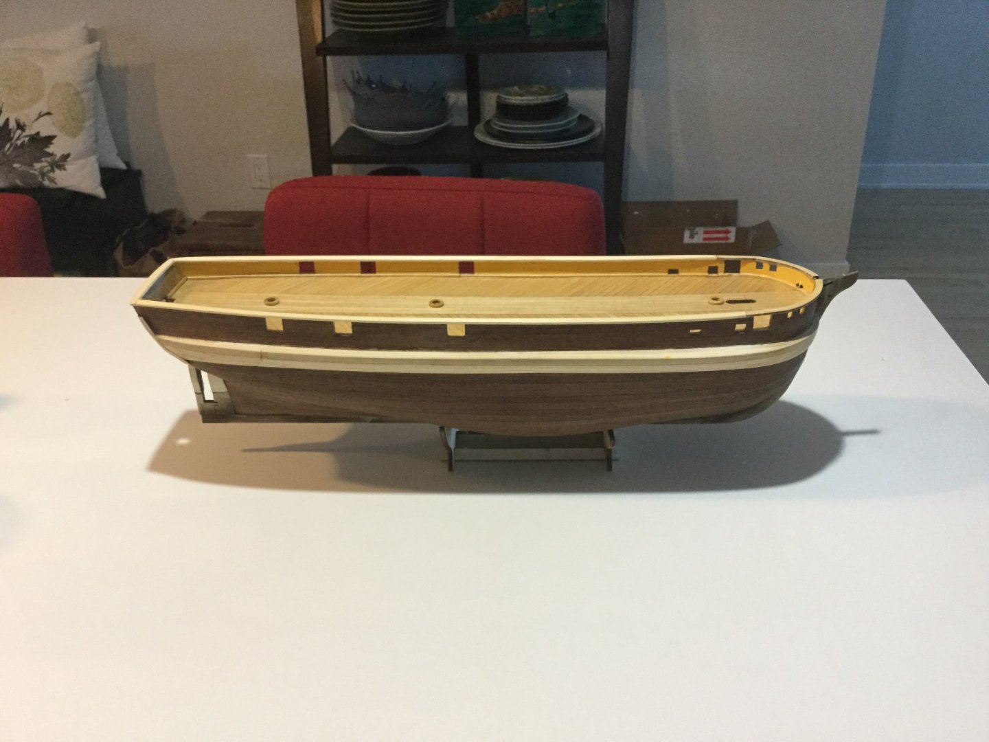
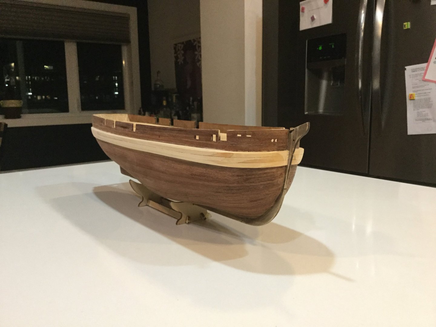
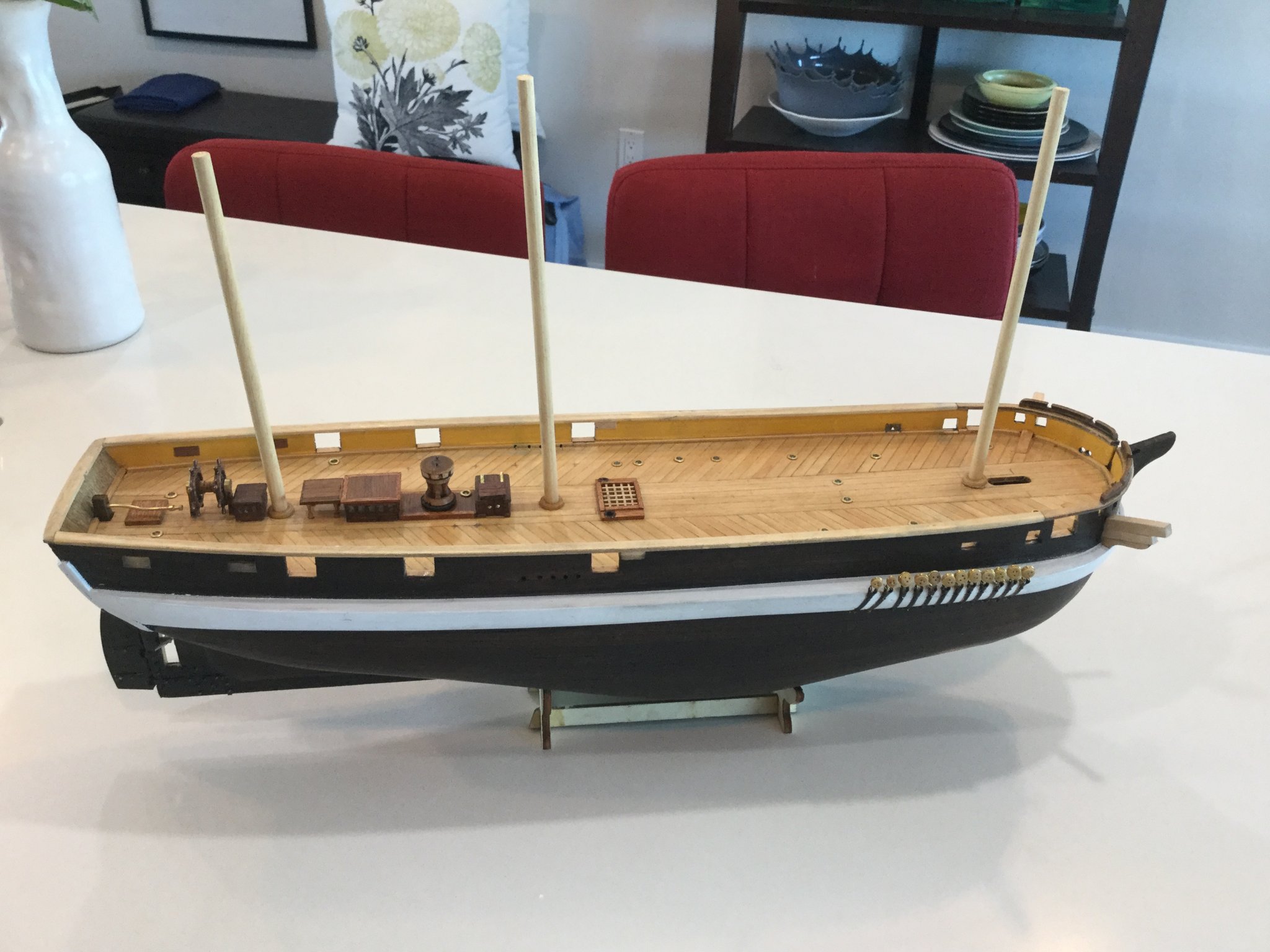
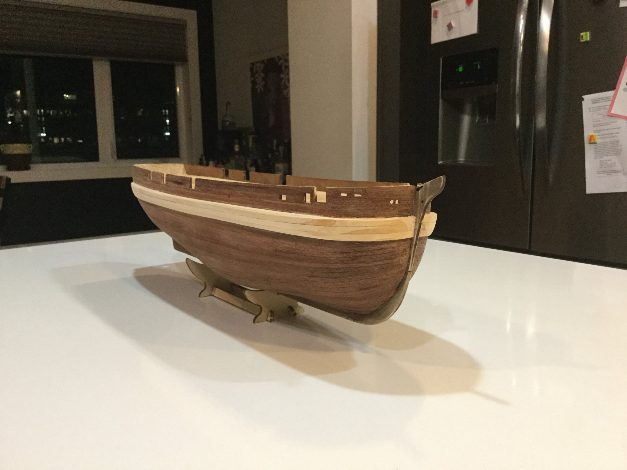
The kit drawings depict the ship in either a compelling natural-wood finish, or painted to represent the ship how she really looked. I wanted to paint her, but my wife and friends thought she looked good in natural wood. I decided to compromise and stain the hull in minwax "ebony" stain. I painted the ice chocks white. I think this worked out quite well, preserving the lovely grain of the sapele wood while darkening it enough to suggest a realistic black colour scheme.


-
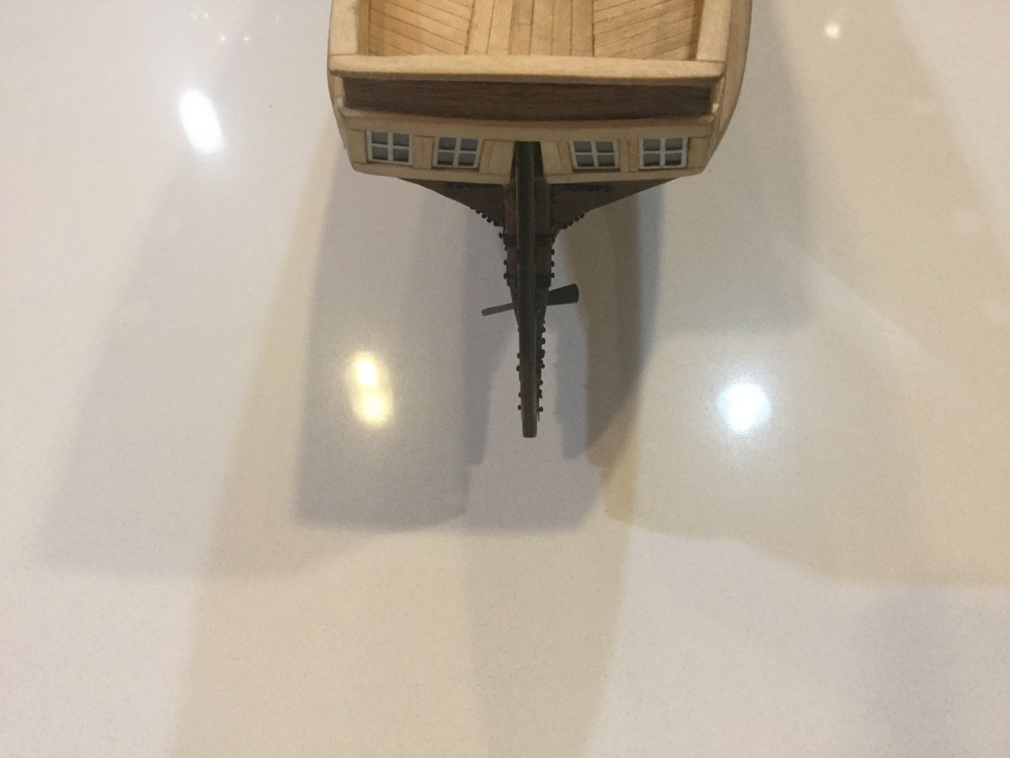
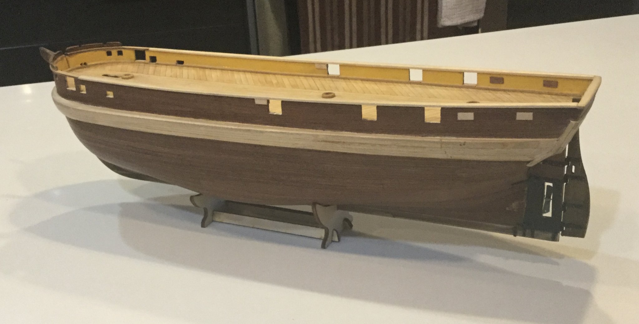
Here are pictures of the iron-work around the Terror's propeller aperture. The ship's stern-post and rudder were moved aft to make room for the retractable propeller. To retain strength, the whole contraption was banded up with heavy iron straps which in the model are represented by etched brass bands and small brads to represent the huge rivets. I feel this is a part of the kit which is really well done and really captures the essence of this early industrial-revolution addition to an age-of-sail structure. I chemically blackened the brass and touched it up with some black paint.
-
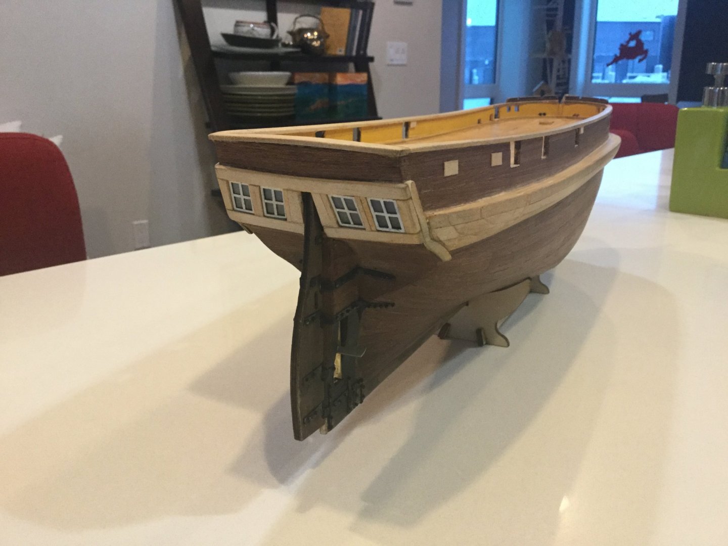
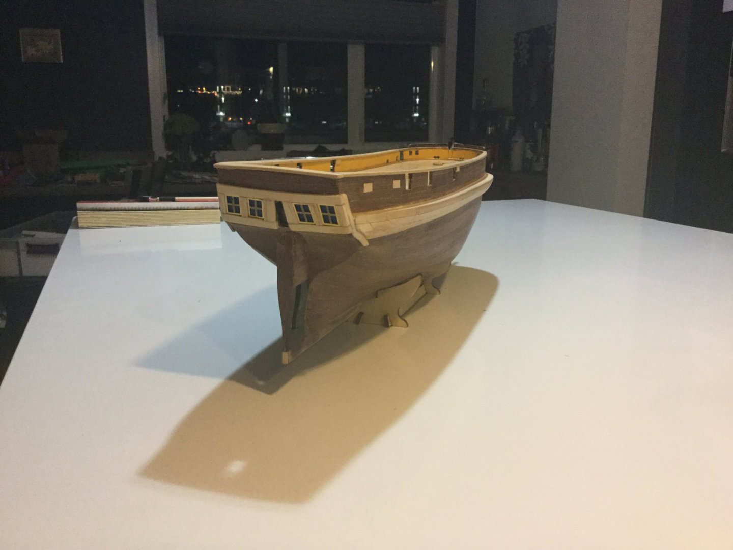
Here I have worked on the stern windows and painted the inner bulwarks. Via Mr. Betts' research on his blog, I read a written conversation between the Lords of the Admiralty and the shipwright who prepared the ship for this expedition, in which their Lordships requested a description of the ships' colour scheme to aid in identifying them during the search for them. It was indicated that the "inner weatherworks" were painted yellow, so I painted the inner bulwarks on my model the same. There is no way to know if this is correct, other than possibly there might be paint left on the actual ship. We may find out someday. However, I think the yellow colour looks OK.
As for the windows, I first painted the wood on the transom in horizontal gradations of dark to very dark blue. Then I glued acetate "glass" behind the brass frames, which were painted white. I feel this reproduces the look of shiny glass with a dark room behind.

- GrandpaPhil, Dean77, BobG and 4 others
-
7
-
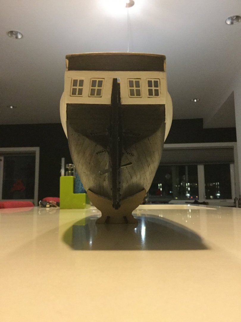
The "ice chocks" are built up from about five layers of wood strips which are then planed and carved to shape. On the real ship, this was built up in an attempt to protect the chain plates from being pulled away by ice. My examination of drawings of the real ship made me suspect the measurements in the kit were off by about five mm, therefore I lowered the ice chock by that amount and sent a message to OCCRE. I feel that the ice chock on my model is in the correct position.
-
-
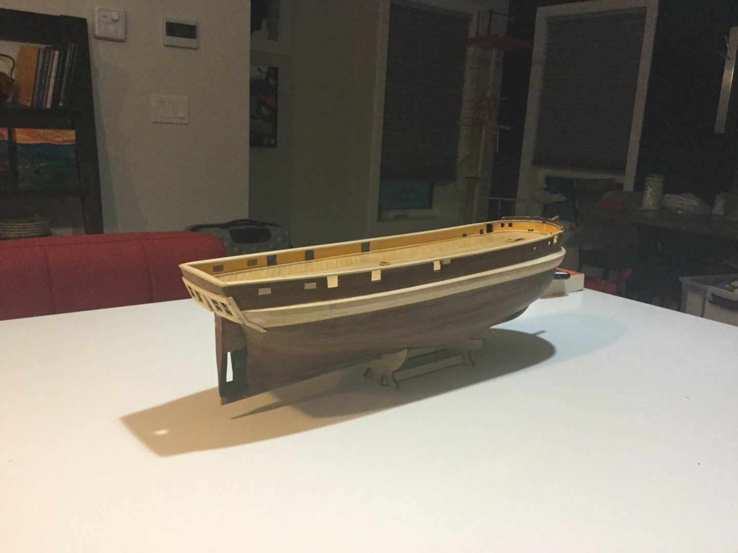
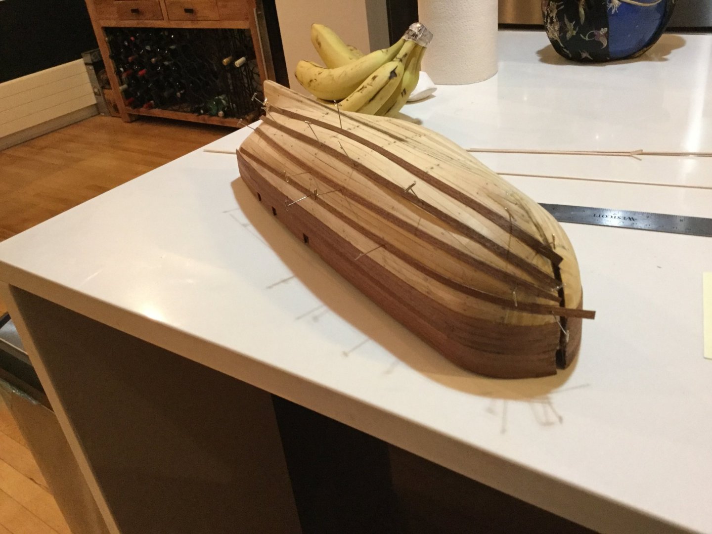
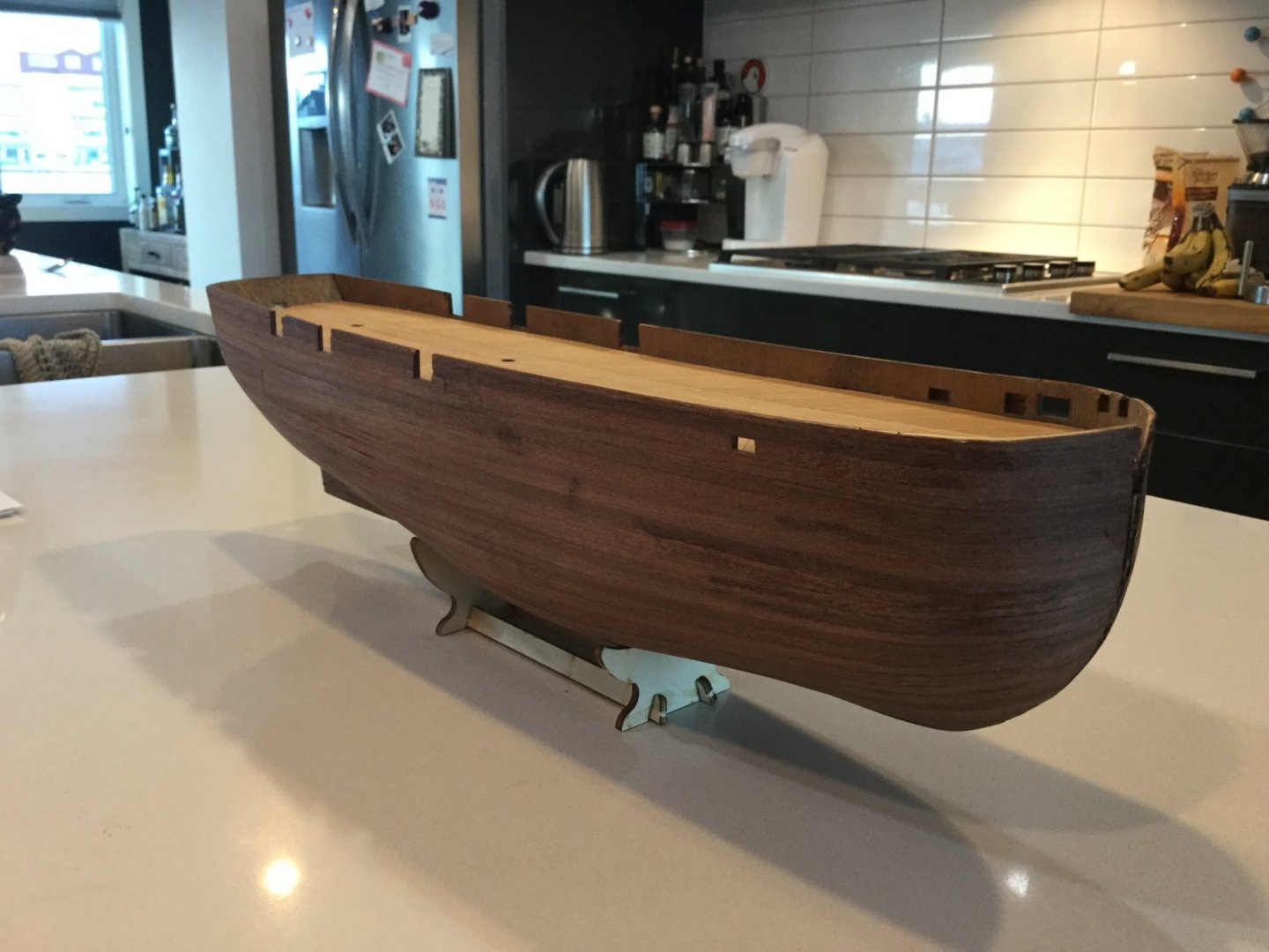
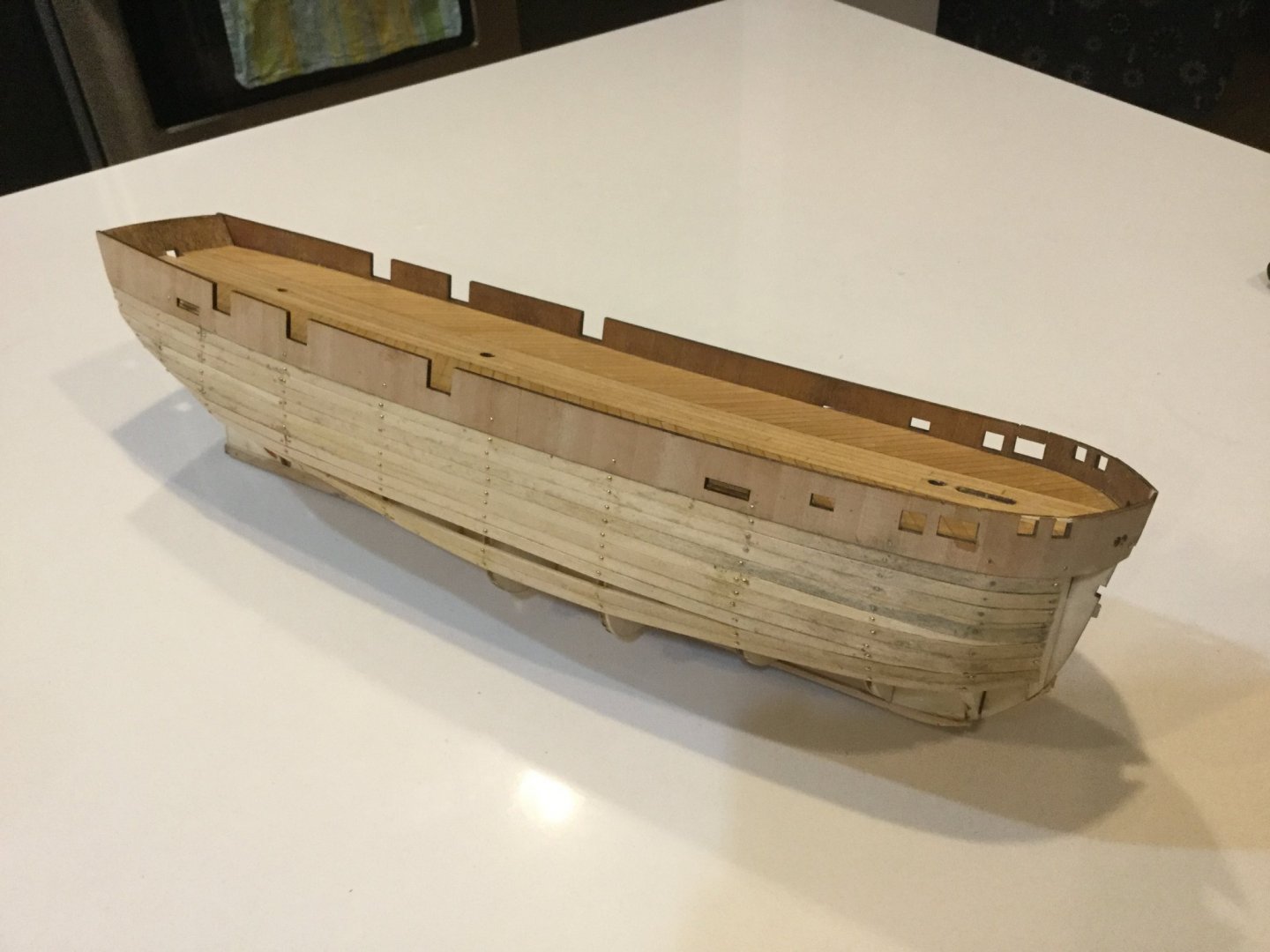
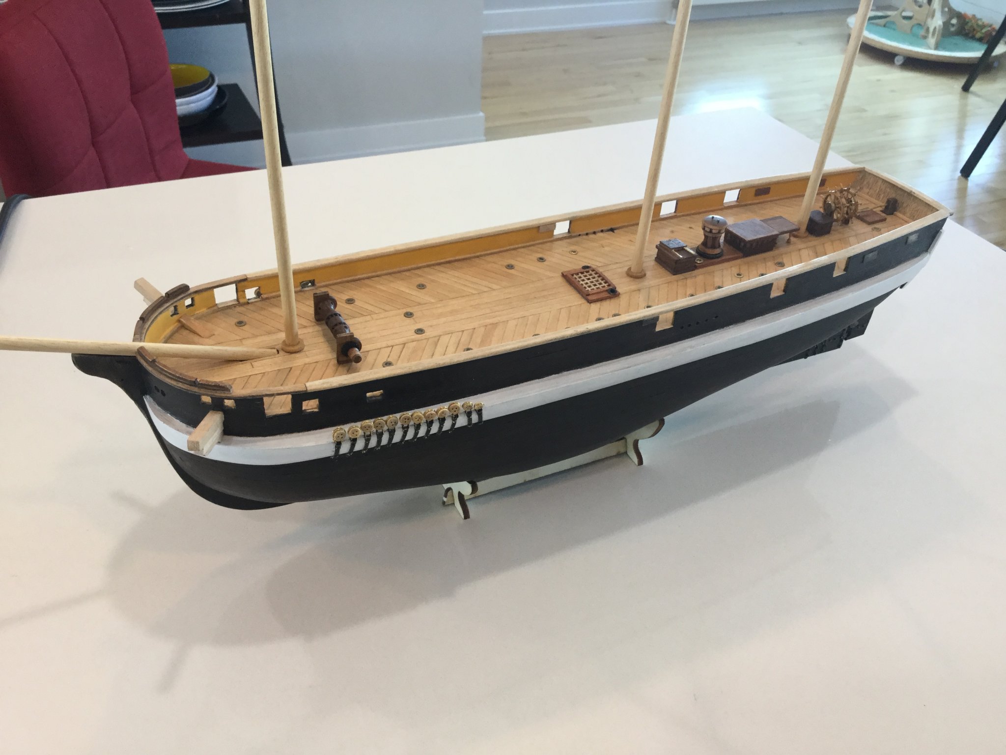
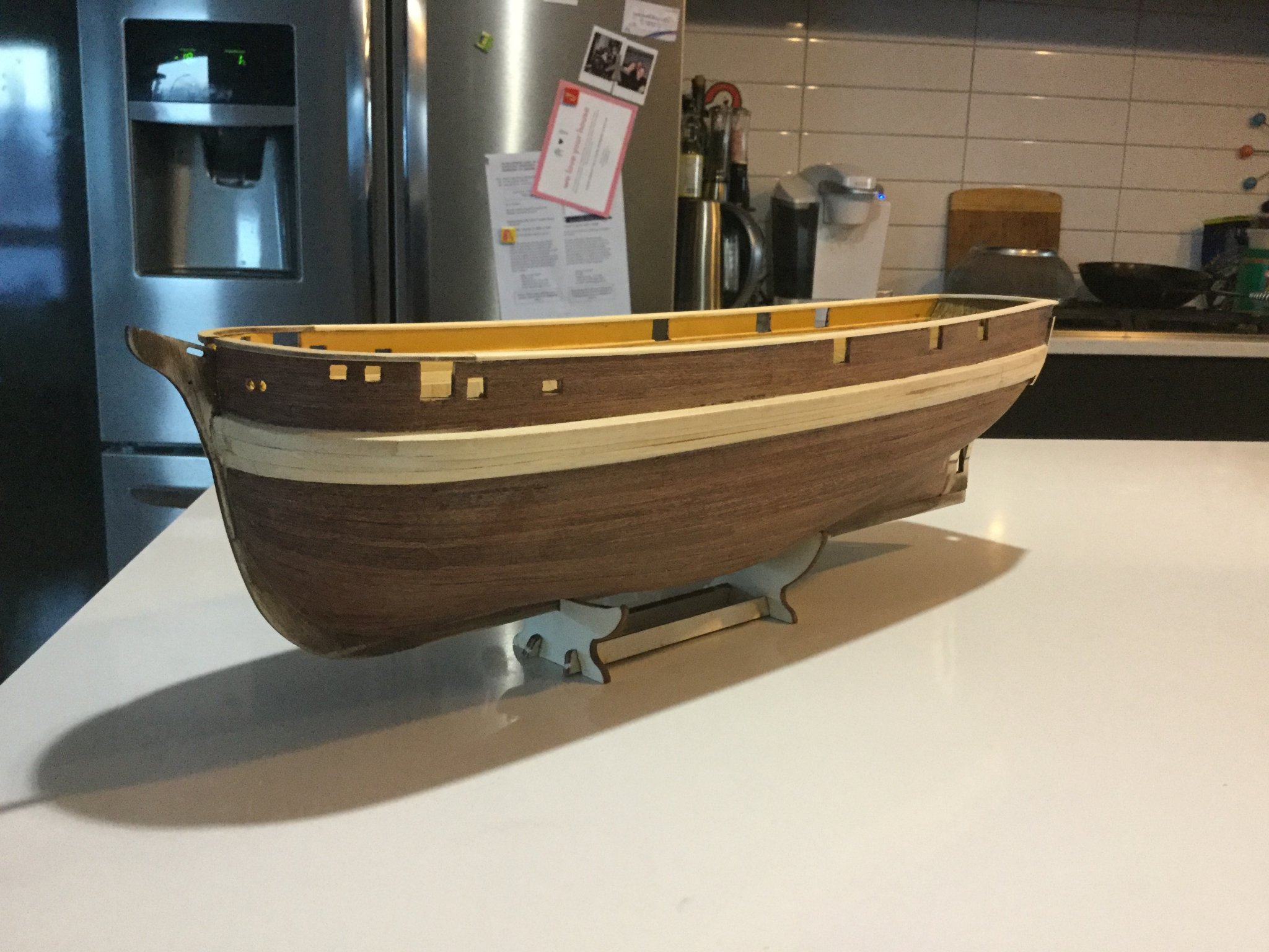
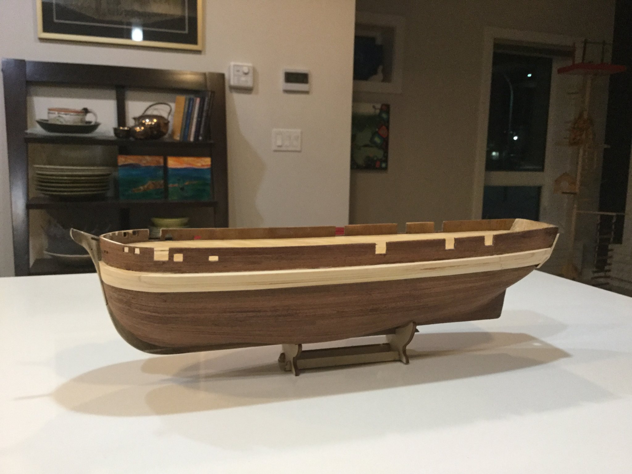
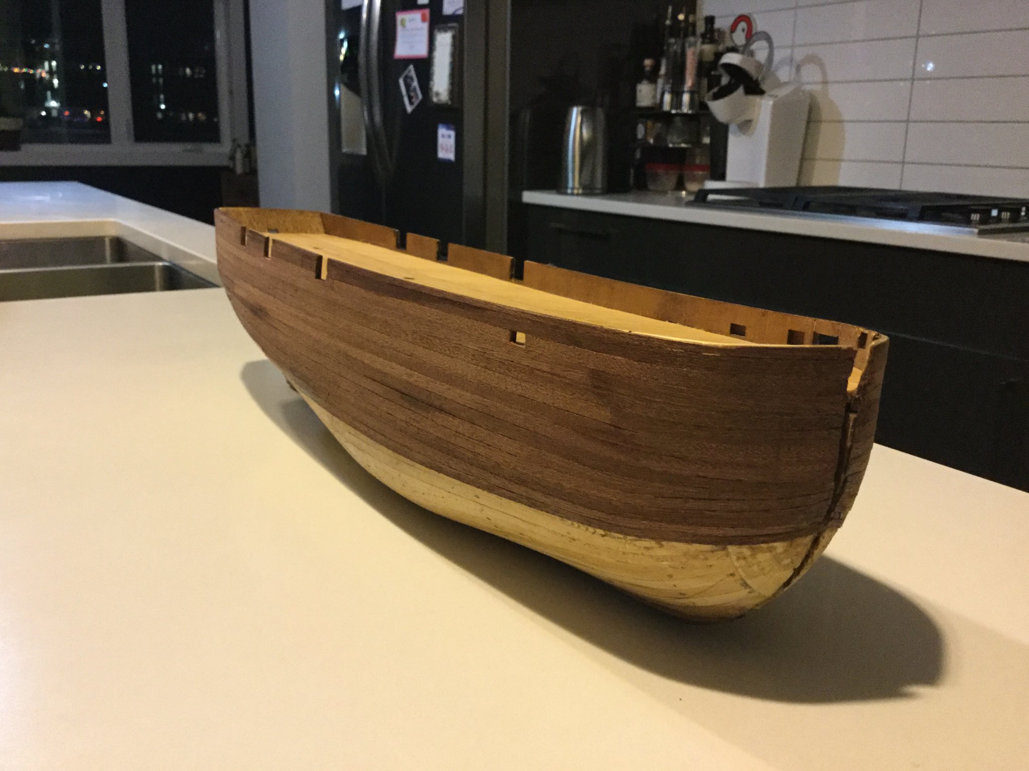
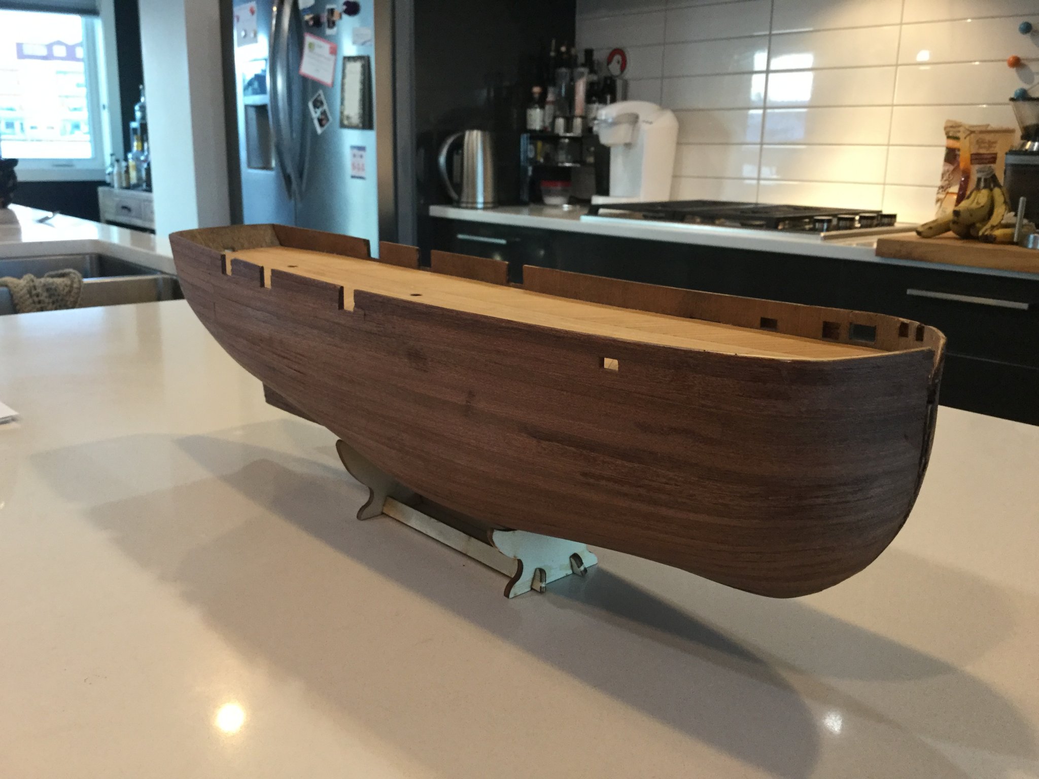
Here you can see how I did the second course of planking on the model. I tried to make the planking a little more realistic by tapering each strake in an attempt to make them lie in a bit more realistic fashion. I understand that to truly "spile" the planks would have required starting with some wider stock than the 5mm strips supplied in the kit, and the result is in no way a "scale" representation of the real ship's planking, but I am fairly pleased with how it turned out. Of course, the real hard work will eventually be completely covered by the metal armour on her bow.


- JayCub, shipcarpenter, NovaStorm and 8 others
-
11
-
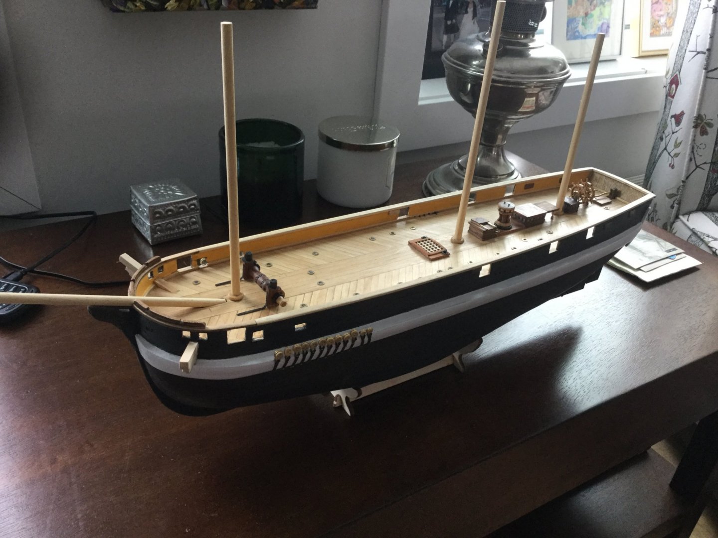
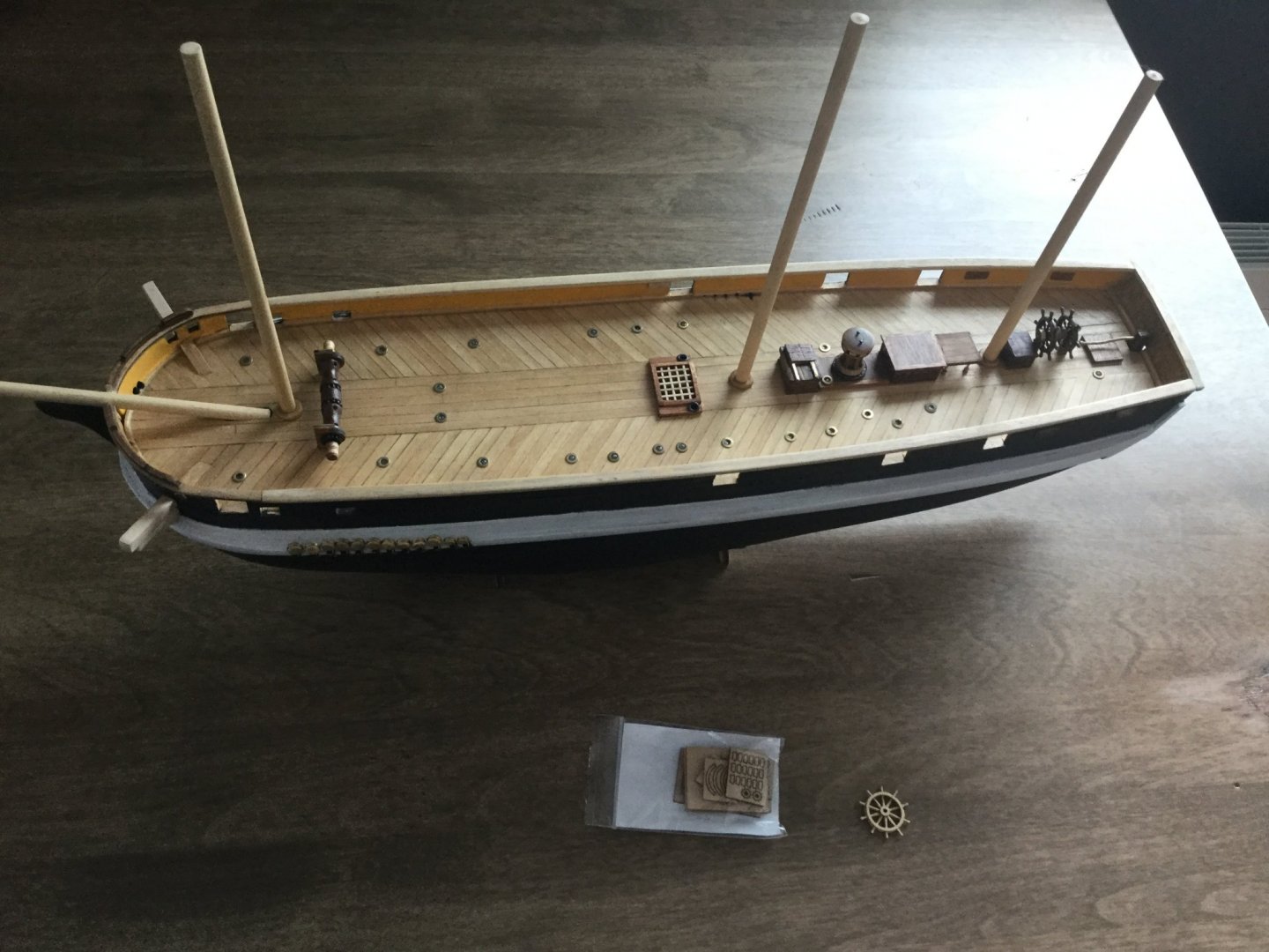
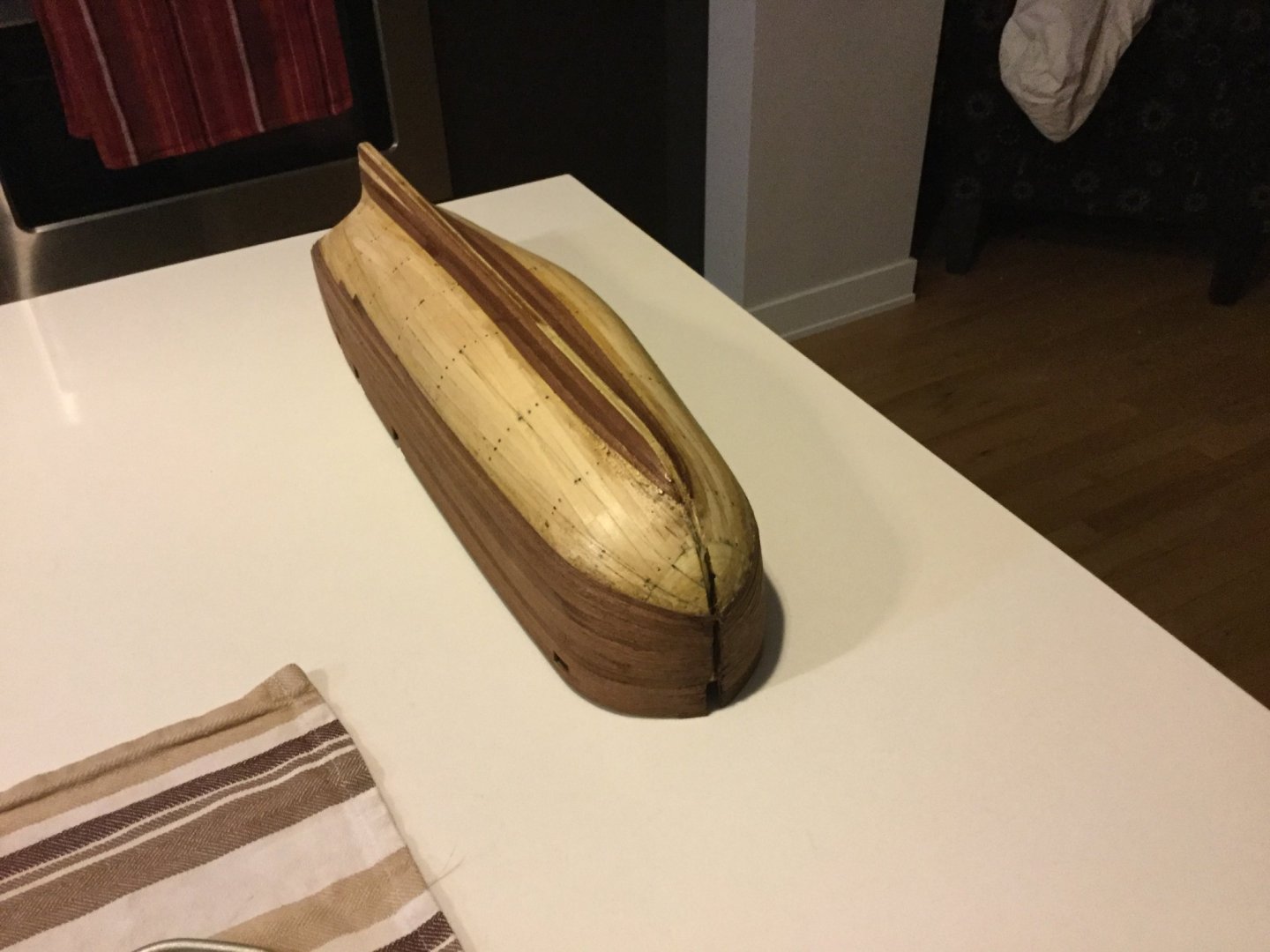
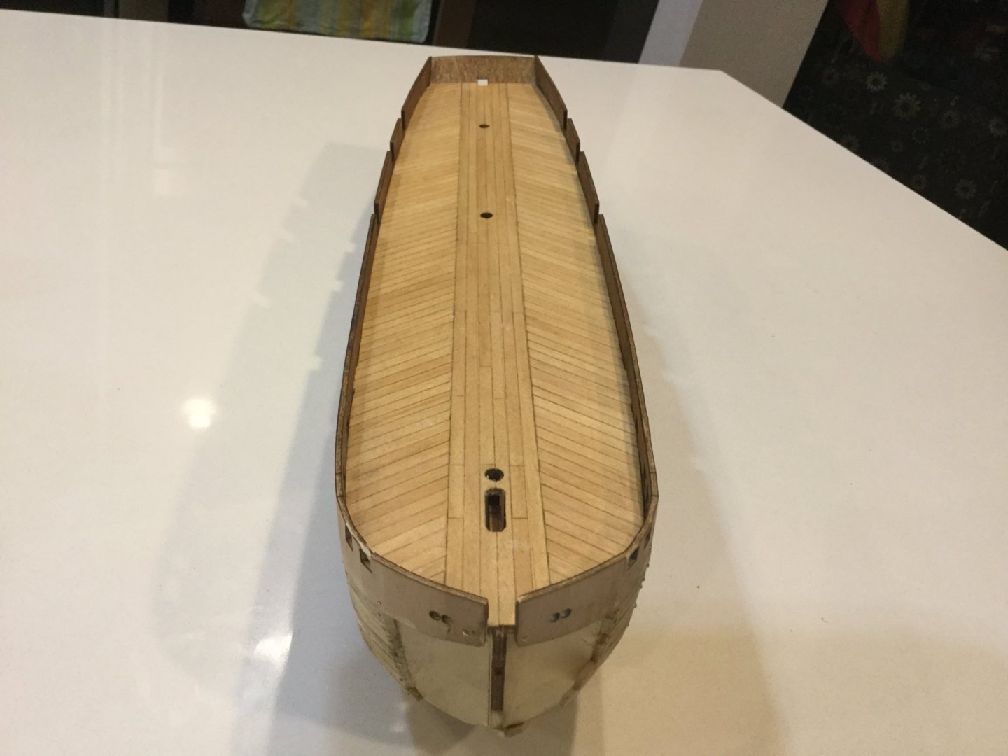
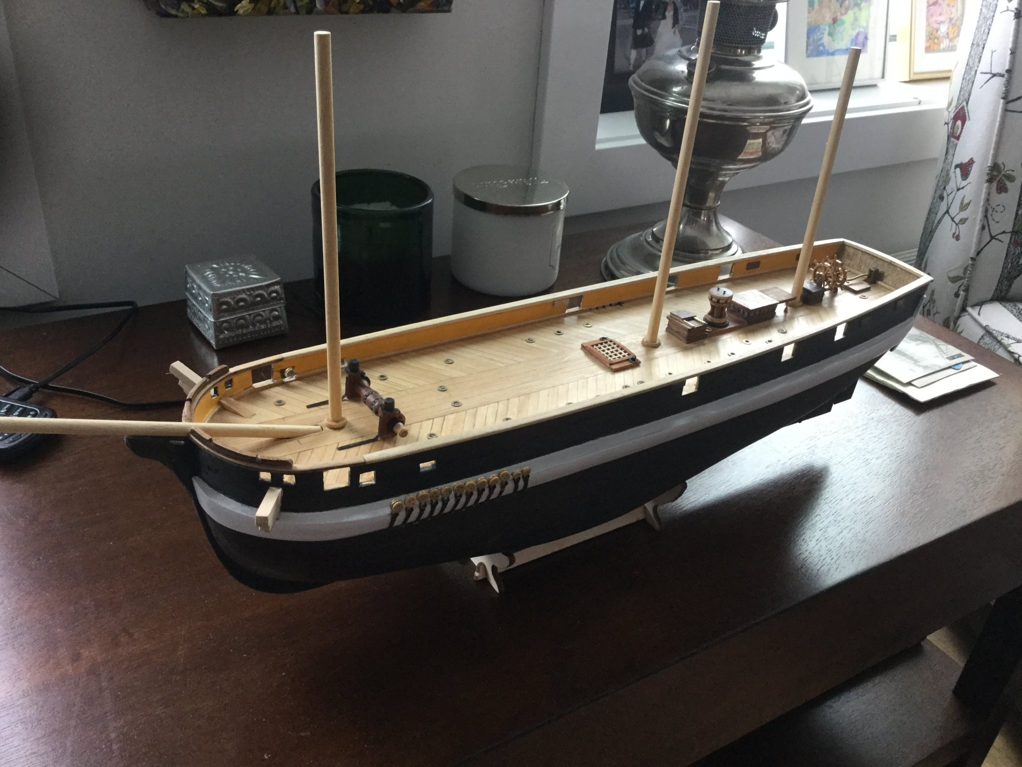
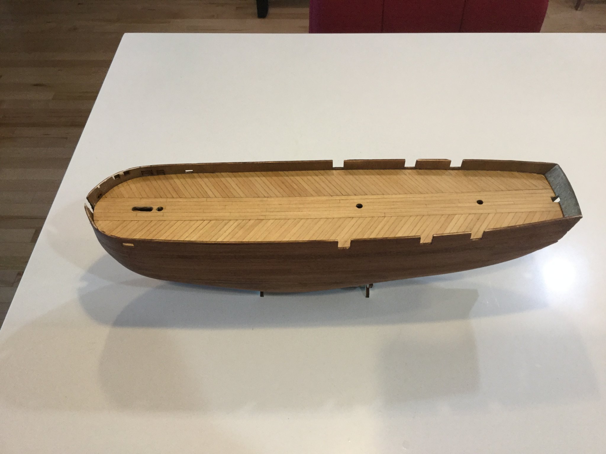
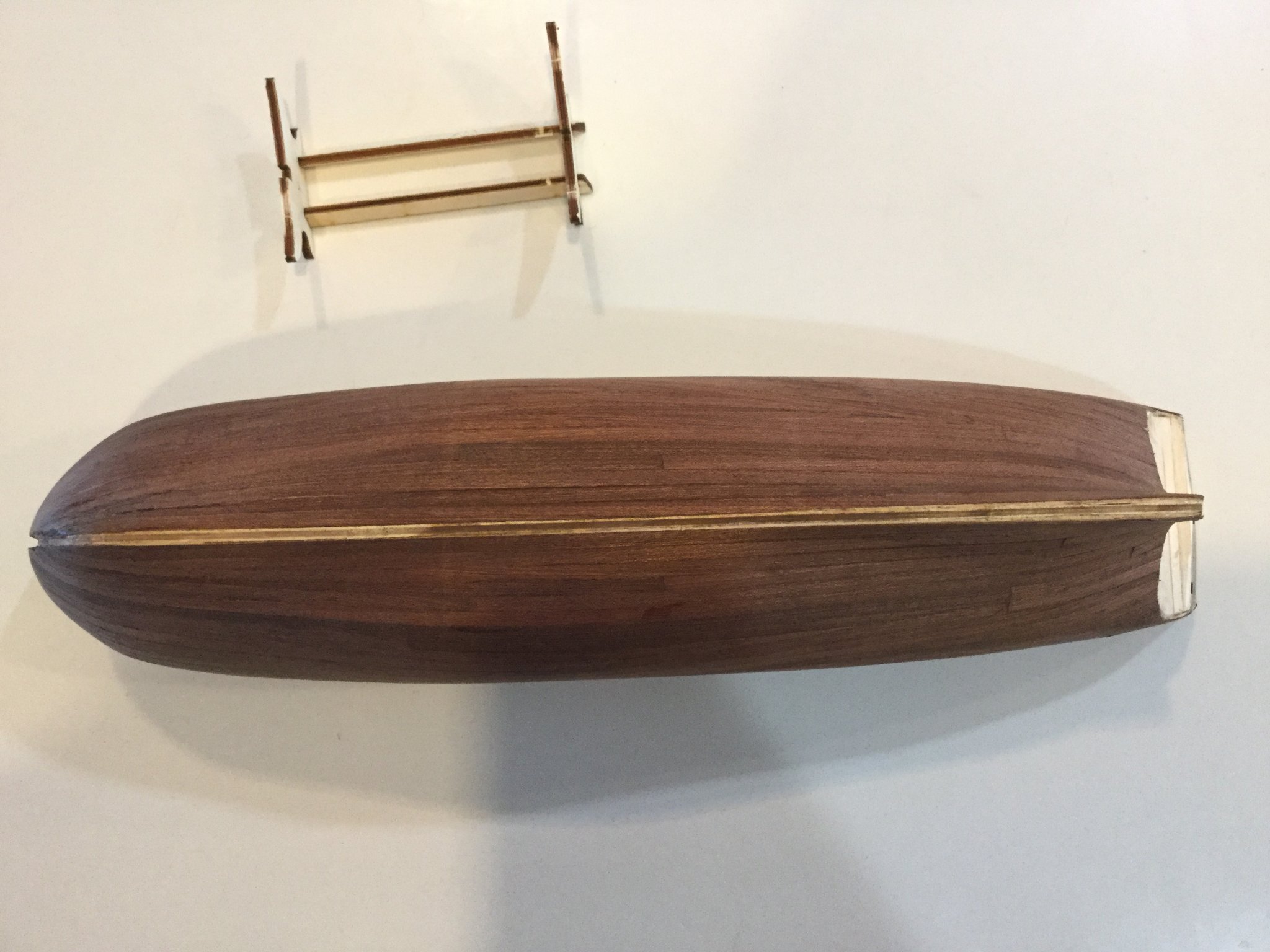
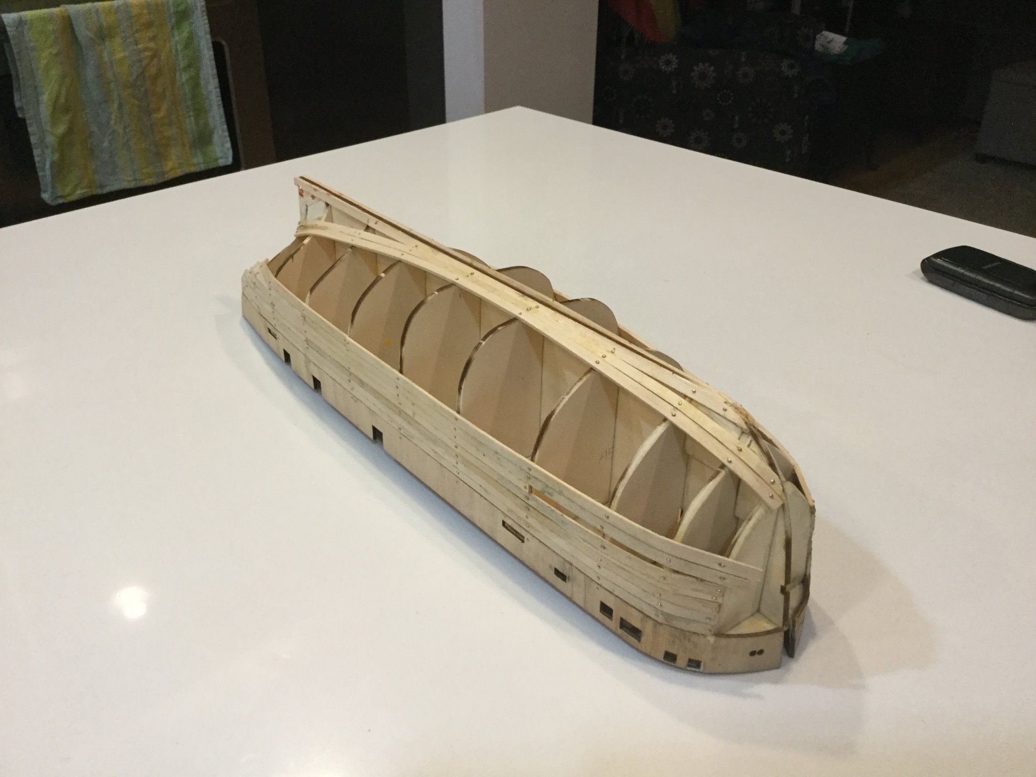
Here is a basic record of the work I've done so far. I do not necessarily build in the sequence set out in the kit instructions.
The first step in this kit is to lay out and glue the hundreds of planks that form the deck, onto the plywood false deck. It's a fiddly exercise that gives the neophyte modeller a taste of the effort that is going to be required to build the ship!


- Jeff preisler, JayCub, Bolithofan and 7 others
-
10
-
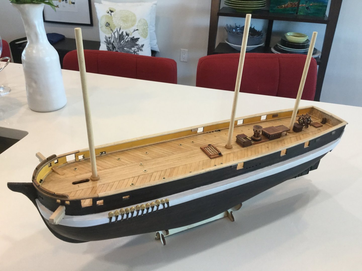
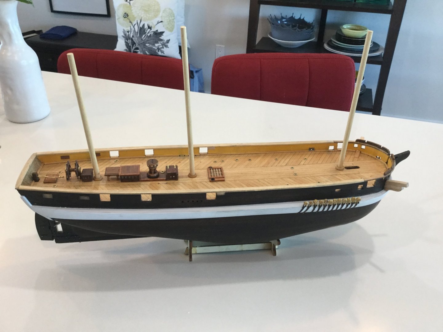
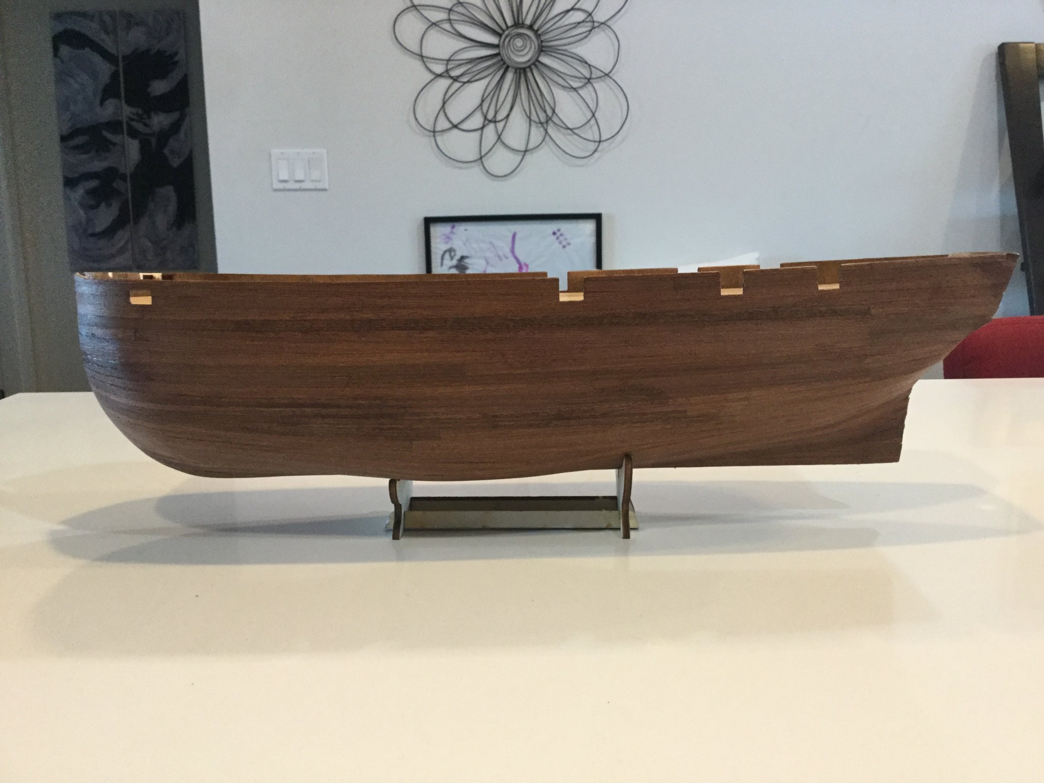
Hi everyone, I'm building the OCCRE HMS Terror model. This is my first ship model, and I described the reasons for wanting to build her in my "new member" introduction. I'm actually a fair ways along with this model, but have reached the point where I have questions about details and Royal Navy standard practice from that era, in an attempt to make my model as accurate as I can. Also I see other people are building this model, and I hope to trade notes with them as I go along. I guess I'll make a series of posts to start off, to show the various stages I went through to get the model to the point she's currently at. I am trying to make some improvements to the basic kit: to this end I have done a bit of research and also received a bit of help from a friend who is very knowledgeable about ships, the Franklin ships in particular, and is very generous with his advice. My model will incorporate some of the things I've learned from photographs of the real ship as she lies today, the kit itself, and also the advice of my friend. Also I have read and re-read the excellent blog by a member of this forum on the subject of HMS Terror, which I will study closely and try to make modifications to the kit to try and emulate.


Live steam Bagnall loco and other railway stuff
in Non-ship/categorised builds
Posted · Edited by Keith S
Hi Michael, I just wanted to say hello and what a pity I only just joined this forum. I used to fly to Edmonton once a week and be a loose ends during the day. Unfortunately I have a different job now. I wish I had been able to make your acquaintance. I live in Yellowknife you see, and I have some narrow-gauge models powered by a Roundhouse locomotive I built several years ago using their kits. I am the only person I know in this continent with an interest in garden railways, and unfortunately don't have a garden. My loco chuffs desolately around in circles on the lounge floor when Mrs. Keith isn't home.
Well just wanted to say hi. I was admiring your work on the "model" cutter, and now I see you like steam engines as well. You must be an interesting chap. Cheers.