Model Mariner
-
Posts
95 -
Joined
-
Last visited
Recent Profile Visitors
1,907 profile views


-
 Archi reacted to a post in a topic:
Berlin 1674 by Model Mariner - scale 1:64 - Navy Board style
Archi reacted to a post in a topic:
Berlin 1674 by Model Mariner - scale 1:64 - Navy Board style
-
Archi reacted to a post in a topic:
Berlin 1674 by Model Mariner - scale 1:64 - Navy Board style
-
Archi reacted to a post in a topic:
Berlin 1674 by Model Mariner - scale 1:64 - Navy Board style
-
Saburo reacted to a post in a topic:
HMS Naiad 1797 by EdT - FINISHED - 1:60 - 38-gun frigate
-
Siegfried reacted to a post in a topic:
Berlin 1674 by Model Mariner - scale 1:64 - Navy Board style
-
Siegfried reacted to a post in a topic:
Berlin 1674 by Model Mariner - scale 1:64 - Navy Board style
-
Siegfried reacted to a post in a topic:
Berlin 1674 by Model Mariner - scale 1:64 - Navy Board style
-
flying_dutchman2 reacted to a post in a topic:
Seawatch Books outside of the US
-
Model Mariner reacted to a post in a topic:
HMS Atalanta 1775 by tlevine - FINISHED - 1:48 scale - from TFFM plans
-
Model Mariner reacted to a post in a topic:
Young America 1853 by EdT - FINISHED - extreme clipper
-
Model Mariner reacted to a post in a topic:
HMS Winchelsea - FINISHED - 1764 - by Chuck (1/4" scale)
-
Model Mariner reacted to a post in a topic:
HMS Winchelsea - FINISHED - 1764 - by Chuck (1/4" scale)
-
Model Mariner reacted to a post in a topic:
HMS Winchelsea - FINISHED - 1764 - by Chuck (1/4" scale)
-
Model Mariner reacted to a post in a topic:
HMS Winchelsea - FINISHED - 1764 - by Chuck (1/4" scale)
-
Model Mariner reacted to a post in a topic:
Young America 1853 by EdT - FINISHED - extreme clipper
-
Model Mariner reacted to a post in a topic:
Young America 1853 by EdT - FINISHED - extreme clipper
-
Model Mariner reacted to a post in a topic:
Young America 1853 by EdT - FINISHED - extreme clipper
-
Model Mariner reacted to a post in a topic:
HMS Winchelsea - FINISHED - 1764 - by Chuck (1/4" scale)
-
GrandpaPhil reacted to a post in a topic:
Berlin 1674 by Model Mariner - scale 1:64 - Navy Board style
-
GrandpaPhil reacted to a post in a topic:
Berlin 1674 by Model Mariner - scale 1:64 - Navy Board style
-
Hi.
Have been looking for plans for the Mayflower.
I am interested in a cross section of the middle mast area.
Would you be willing to share your work / resurch ?
Any help would be appreciated.
Regards Antony.
-
 Congratultions for finishing this stunning model, what you have achieved is more than amazing! Klaus
- 883 replies
-
- 1
-
-
- royal caroline
- ship of the line
- (and 1 more)
-
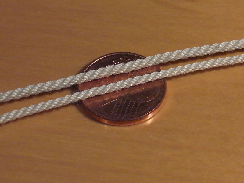
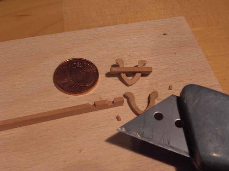
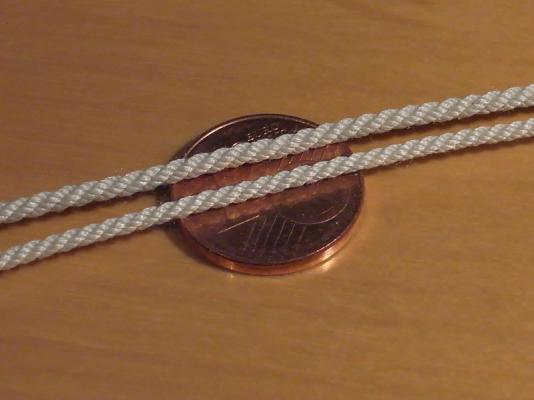
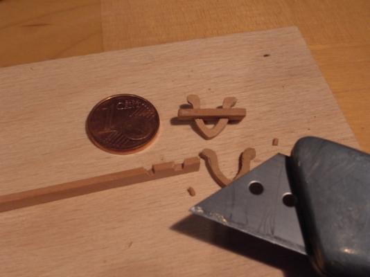
If there were not fingertips in one of the pictures I would have asked where you have got the hugecent coin from! Very nice work as always. Klaus
-
I like the color of the ropes. What did you use for dyeing? Klaus
- 662 replies
-
- 3
-
-
- bonhomme richard
- frigate
- (and 1 more)
-
Which compliment could I add here which has not already be payed several times? Whatever, even if it is for the umpteenth time: brilliant workmanship, a great build an a great log! Always looking forward for the continuation Klaus
- 3,618 replies
-
- 1
-
-
- young america
- clipper
- (and 1 more)
-
Right Jan, it should read 645mm, thanks for the note. I have corrected the typo in the previous post Klaus
-
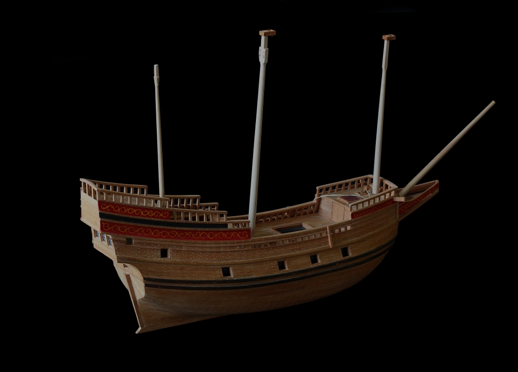
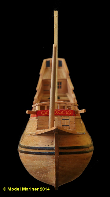
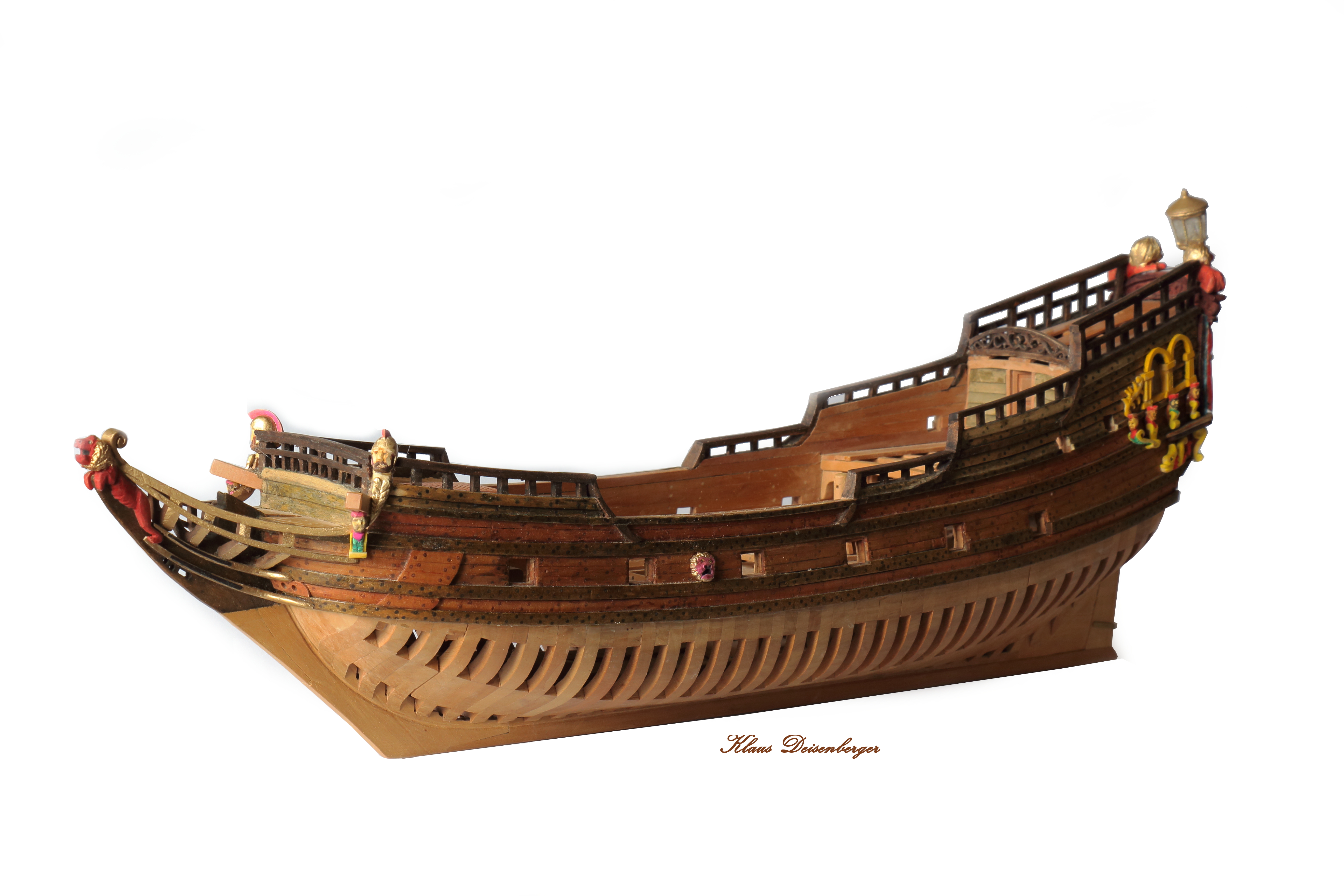
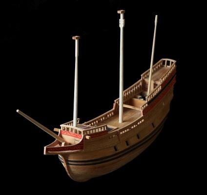
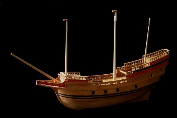
Hi Charlie lenght of the hull (including beakhead) is 544 mm / 21 3/8" lenght including bowsprit is 645 mm / 25" height (not considering an eventual flagstaff) is 504 mm / 19 7/8" Klaus
-
I would vote for natural Klaus
-
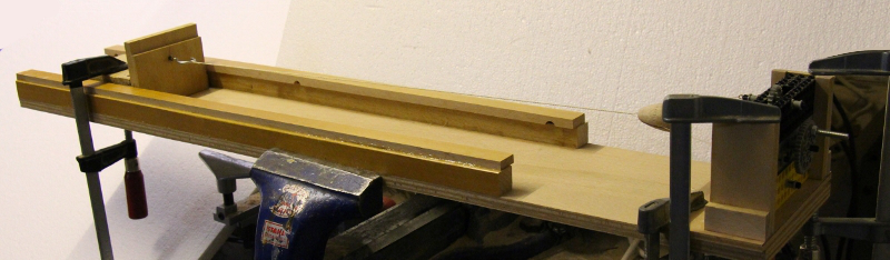
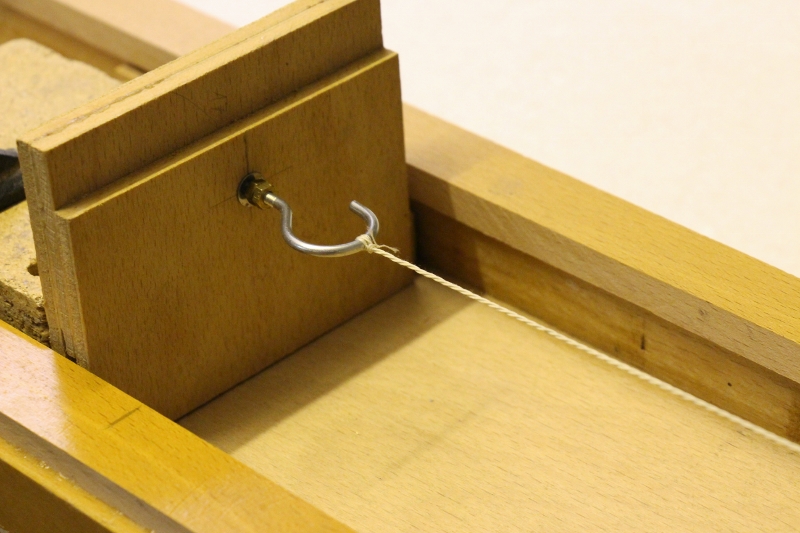
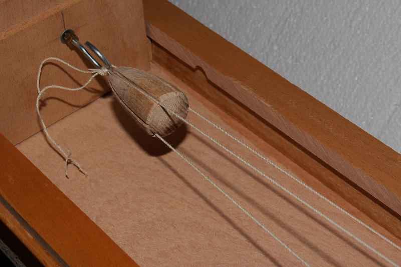
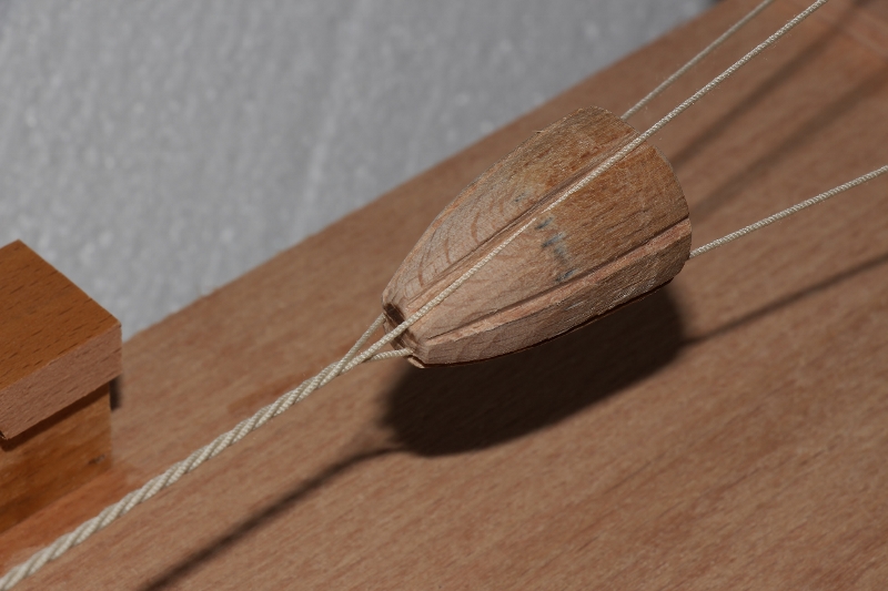
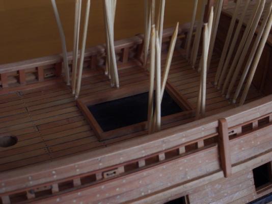
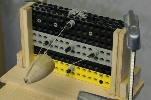
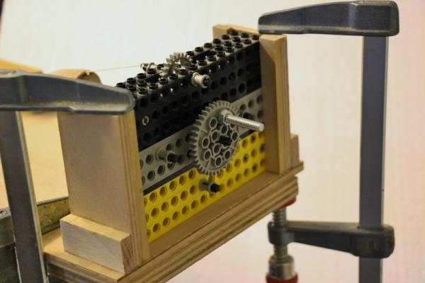
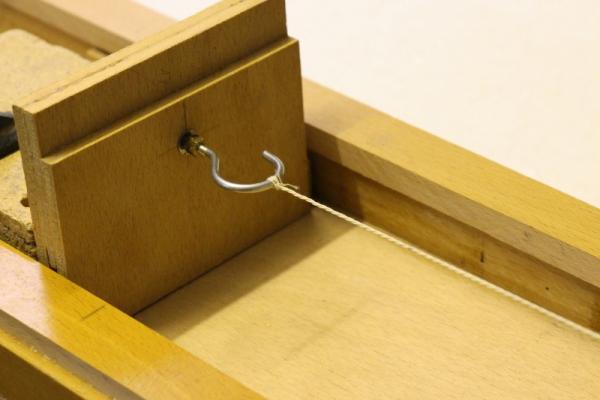
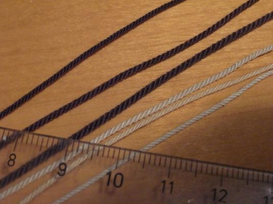
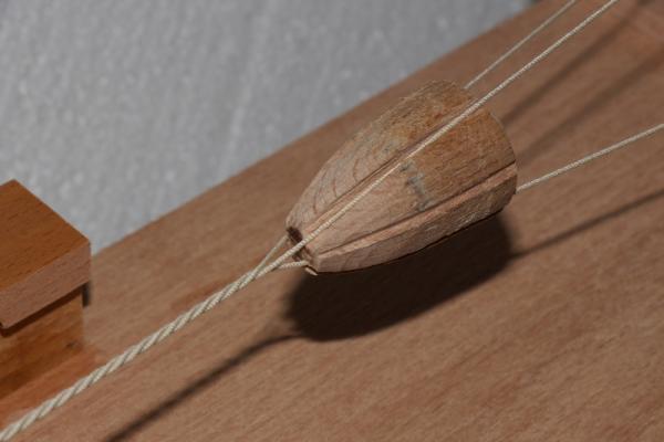
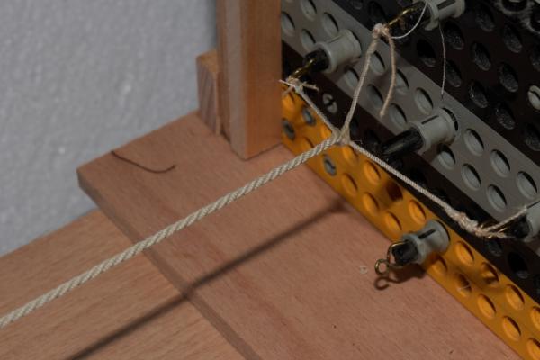
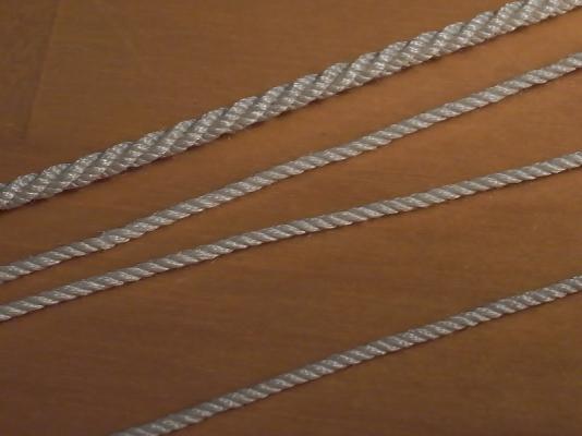
Thanks for the comments and likes folks I have glued in the kevels for the sheets of the main course and have installed some sheave blocks for the sheets fo the courses and the spritsail as well as for the tack of the main course. Having done that I intended as next step to build in the half deck but then I decided to treenail also the deck planks, so there's another 750 plus treenails to put in. For these I drilled holes 0.6 mm diameter and glued in the tips of toothpicks: Before closing the half deck I intend to belay the sheet of the main course on the respective kevels under the deck because these are not easy accessible later on. The sheets and tacks are cable laid rope which is not (or hardly) commercially available in the diameters I need, for this reason I will make my own ropes. Rope making: I have made a simple rope-making machine, the planet gear for the looper is made by means of Lego components. I made 4 hooks to be able to make three as well as four stranded rope. The traveller is simply an angle made up of plywood with a hook which is mounted in a way that it is easily rotatable and the top a wooden cone with some slots in it. I prefer to fix the looper with clamps rather then screwing it on permanently because this gives me more flexibility to produce ropes of whatever lengths I want to produce. I have started now test using different kinds of thread in order to find out how many threads of which diameter I need to get the required various ropes. The next picture shows some (test) hawsers of different diameters, all laid left handed (although hawsers are usually laid right handed): Making of a cable: For those who are not familiar with the different kinds of ropes: a cable is a 9 stranded left laid rope made of three right laid three stranded ropes (hawsers) The three hawser attached to the hook of the traveller in the grooves of the top, the hawsers are not yet twisted the cable starts to build up: the finished cable at the looper: This is a cable (approx. 1.7 mm diameter) and the three hawsers which are used to lay it. 2 cables with diameters 1,7 and 1,4mm: Klaus


-
Beautiful model, very nice work! In case you have not noticed: a lot of photos on pages 5 and 6 are not visible. It would be nice if you could re-post them. Klaus
-
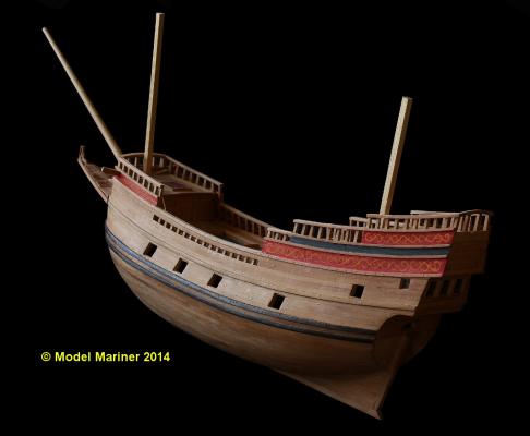
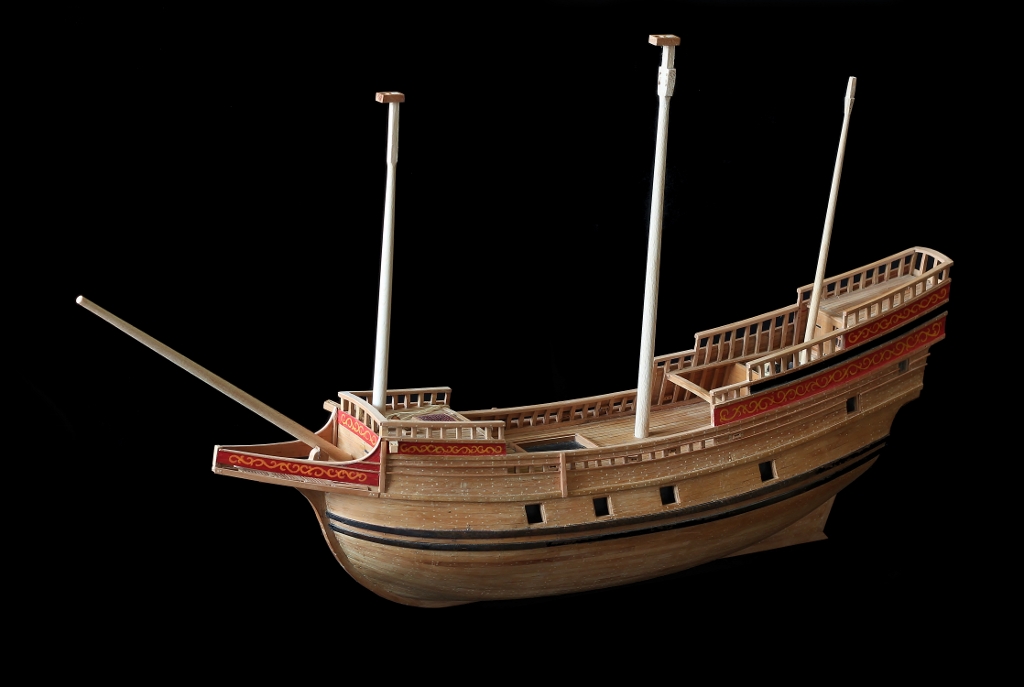
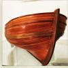
Current status of my model: The lower masts are just put in temporarily, their angles are not yet correct Klaus


-
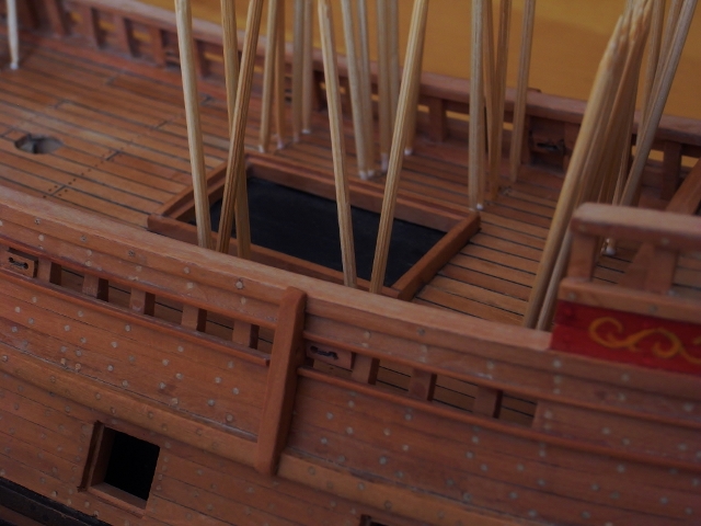
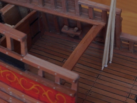
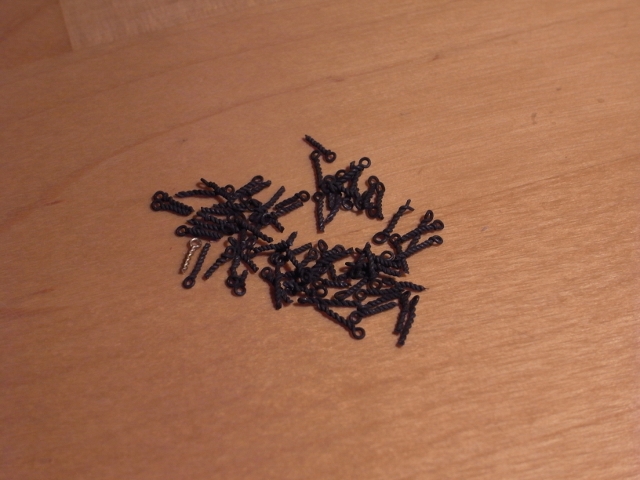
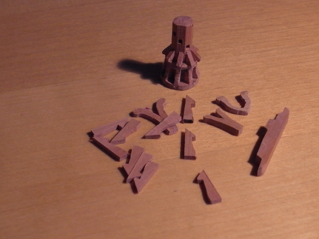
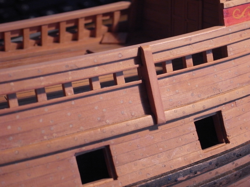
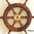
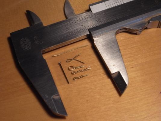
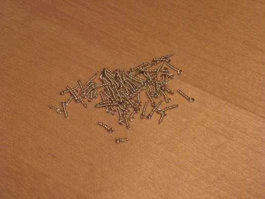
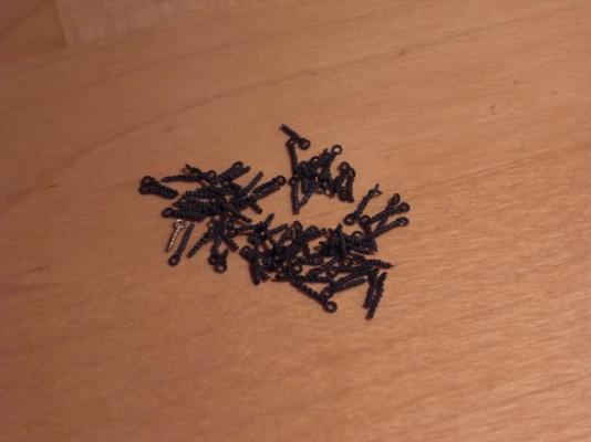
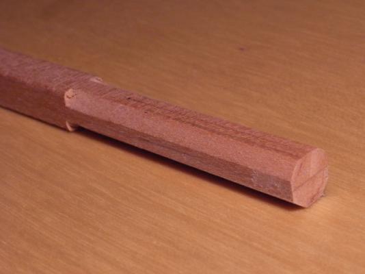
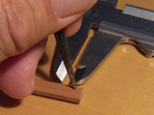
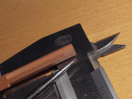
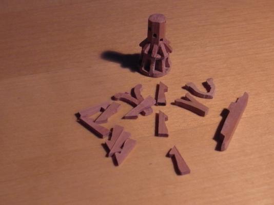
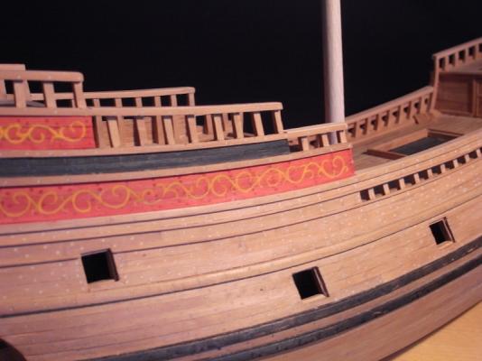
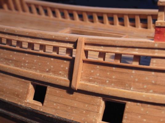
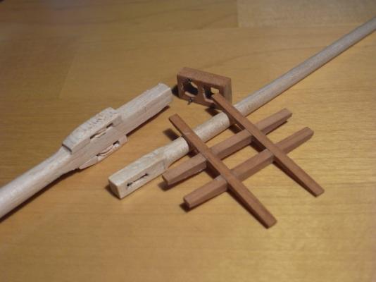
A lot of small stuff is required now, eye bolts, kevels, a capstan etc. and I have started to produce these. Eyebolts: I made eyebolts by twisting brass wire (0.4 mm dia) around a 0.5 mm steel bolt. The twisted part is approx. 0.6 mm thick: I was not really succesful when I tried to make smaller eyebolts but I think for the scale 1:64 I can live with this size, this is what one of these eyebolt look like when set into an 0,6 mm hole: I made 75 eyebolts to start with these are the same ones after putting them for approx. 5 seconds into a metal finsiher (Brass Black): The capstan: according to Goodwin capstans had an octogonal shaft in the early 17th century I have marked the holes for the spokes on the shaft then I drilled round holes which I brought afterwards to the required square shape by pushing in the tip of a nail which I had filed to a sharp square: Whelps and chocks are glued to the shaft of the capstan (a lot of tiny corners to be cleaned ). The picture shows also the whelps for a second capstan (for another model), some kevels and one of the required chesstrees: Rails and chesstrees: The last rails have been added to the hull: The chesstrees are not yet glued on ( the holes for the main tacks are not yet drilled into them). Kevels: 8 kevels are required in the waist for the main sail tacks, main sail sheets, fore sail tacks and tacks of the spritsail Masts: Although there is still a lot of work to be done on the hull I have started to make the masts. The picture shows the head of the main mast, the cross trees, the cap and the heel of the top mast: Klaus


-
Congratulations for finishing this beautiful model, Ilhan! I hope you have already plans for the next project and I'm looking forward to a respective build log! Klaus
-
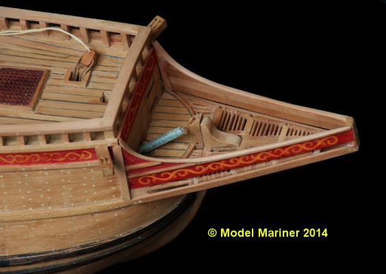
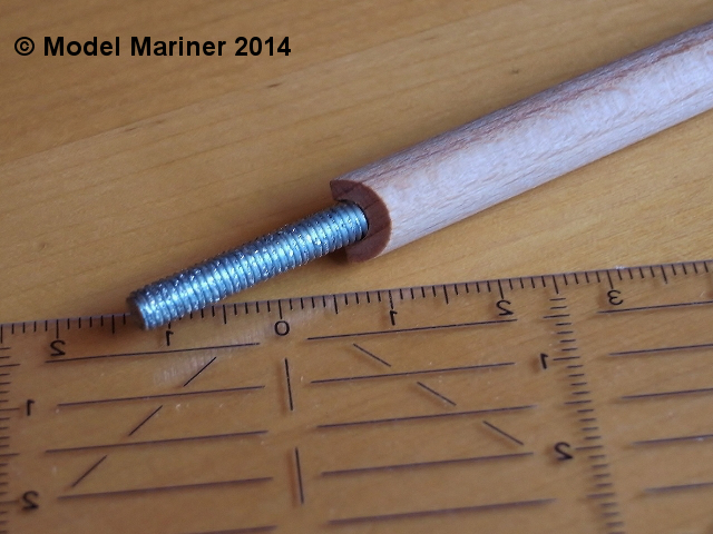
Thanks for the nice comments and the likes I'd like to go back once more to this picture which I have shown already in my last post, which shows a piece of threaded rod set into the hull at the position of the bowsprit: The reason for this threaded rod is that I failed to make a decent funnel (I hope this is the correct English term for it) to insert the bowsprit as I did for the masts. I had provided a hole but it was too small and at this stage I found that it was more than difficult to enlarge it to the correct diameter exactly at the required angle. So I had to think a little bit how to solve this and came to following solution: The bowsprit was already made long enough to be set approx. 50 mm (2 inches) into the hull. I cut it at the position where it is suppossed to enter the hull and I drilled a hole 5 mm dia and about 50 mm deep. The cut had to be made in a way that the bowsprit fits at the correct angle into the angle between the vertical bulkhead and the nearly horizontal deck: Then using a file I enlarged the hole in the hull to a diameter a little bit smaller than the diameter of the bowsprit. I cut then a piece of 5 mm threaded rod to a length of approx. 3 inches. This was pushed into the hole in the bowsprit (not yet glued), over the half sticking out I wrapped some paper soaked with adhesive until it was thicker than the hole in the hull. Then I pressed this into the hole in the hull, fixed the bowsprit at the correct angle and had just to wait for the adhesive to harden. The step of the bowsprit is at the starboard side of the foremast but the tip is supposed to be at the centerline of the ship. In order to align the bowsprits tip with the masts I put square rods into the holes for the fore and mizzen mast, so I could set the bowsprit in line with these dummy masts by looking at the model from the front and from behind . The threaded rod sits now tight in the hull, and I can take to bowsprit off and put it on again when required. I hope this description is not too confusing but I guess with help of the pictures it is clear what i did Klaus