HOLIDAY DONATION DRIVE - SUPPORT MSW - DO YOUR PART TO KEEP THIS GREAT FORUM GOING! (Only 44 donations so far out of 49,000 members - C'mon guys!)
×

Rik Thistle
-
Posts
864 -
Joined
-
Last visited
Content Type
Profiles
Forums
Gallery
Events
Everything posted by Rik Thistle
-
 Good stuff Richard. You'll soon get the hang of it. As I mentioned there are lots of very informative YouTube videos out there that can be of great general help and more specifically on certian model builds.. I think Keith Appleton only started about 4 yrs ago and has very quickly got to grips with it and then some. Although I've never seen/used Sherline equipment I've read they are very well made and highly regarded. So that sounds like a good choice. One final word, and forgive me if I'm teaching my grandmother to suck eggs, but remember to be 'safe'..ie always wear safety glasses and don't let loose clothing (ties, shirt sleeves ect) anywhere near working machinery. And do some practice emergency stops with the Off button to train memory muscle. Have fun 🙂 Richard.
 -
Theodosius, Mark, Thank you for the kind words. It's taken me about a year to go from machine shop beginner to beginner+. Many decades ago I was put through a crash-course workshop 'apprenticeship', but havent used the hands-on side of that for many decades. However, with a bit of practice and perseverance it does (mostly) come back. And these days, there is the internet with all the useful info it can provide. A couple of my favourite YouTubers are Keith Appleton and Blondiehacks ...both well worth watching if you want to get in to this side of the model build hobby. Someone mentioned in a thread here the other day that they tend to have a variety of different hobbies on the go at one time since, I imagine, variety is the spice of life...I'd agree. Regards, Richard
-
Hi Bruce, Yes, you can buy the fully machined, assembled and tested versions of all their products, including the RG ...but they ain't cheap. Thanks for the kind words. The 10V is now sitting between my Dallas and Fifie and seems very happy. I'm sure there's meant to be another ship there also but it seems to still be stuck in the shipyard ...I'll need to find out who's responsible for that ...cough. 😉 Richard
-
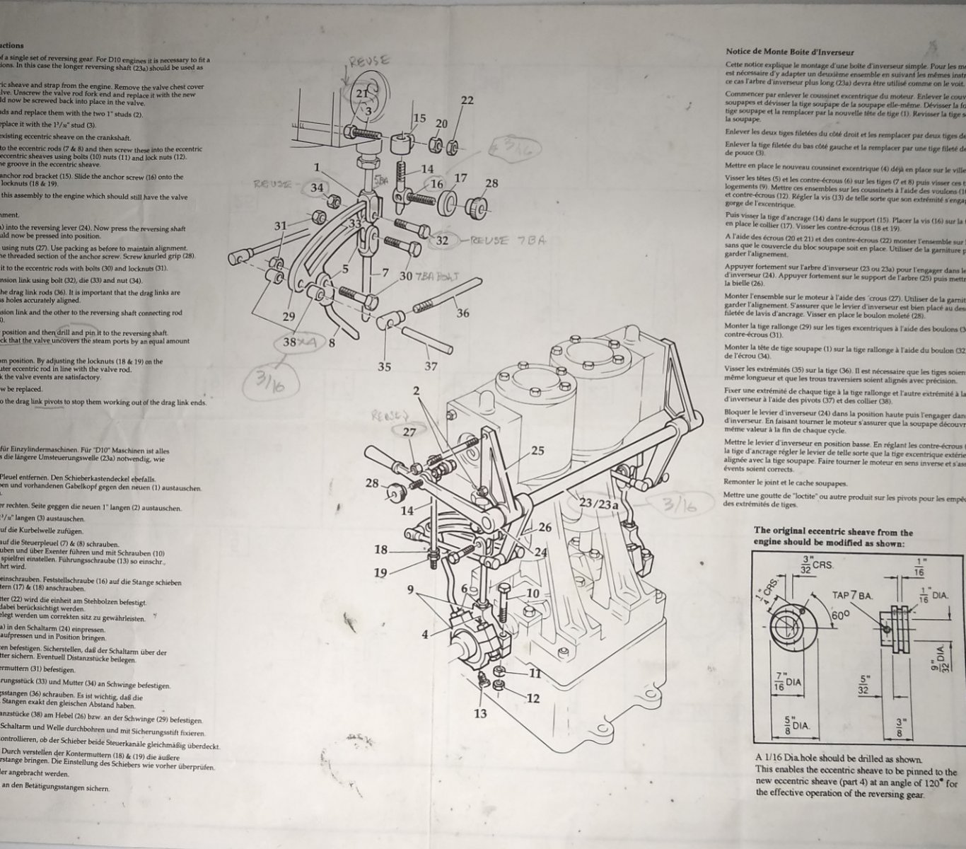
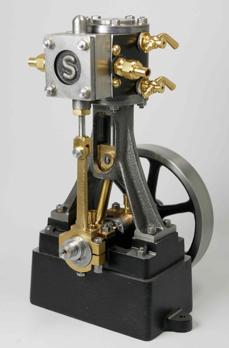
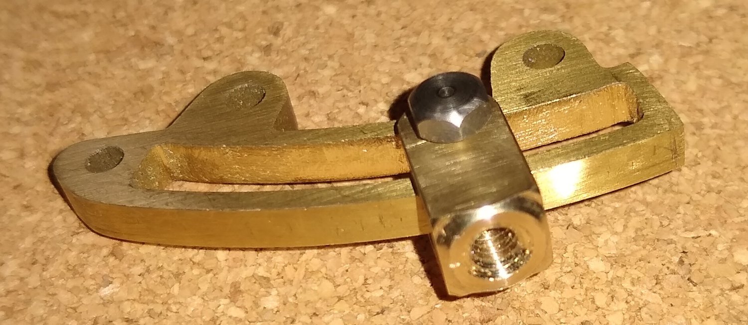
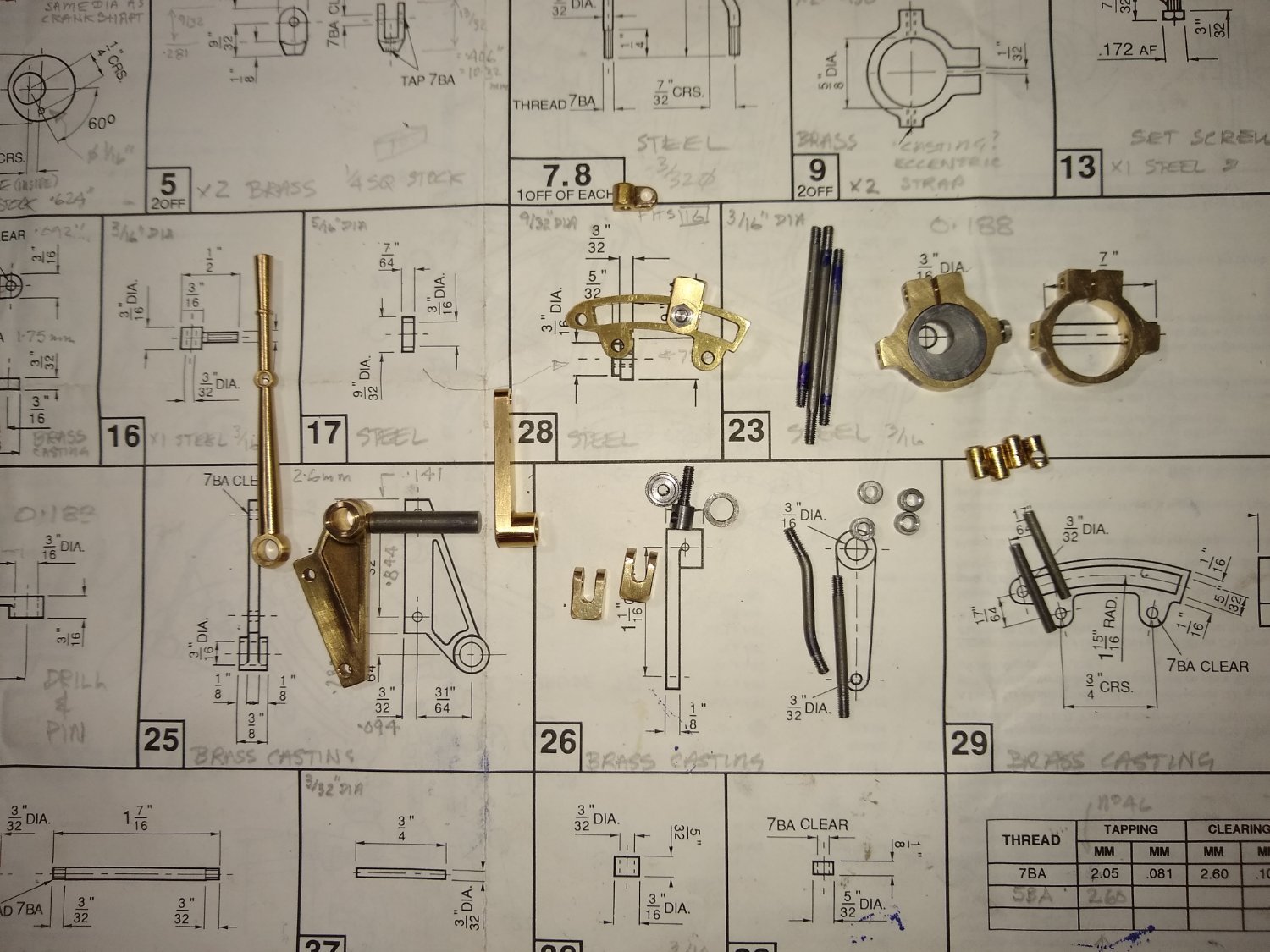
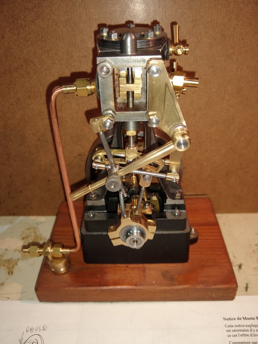
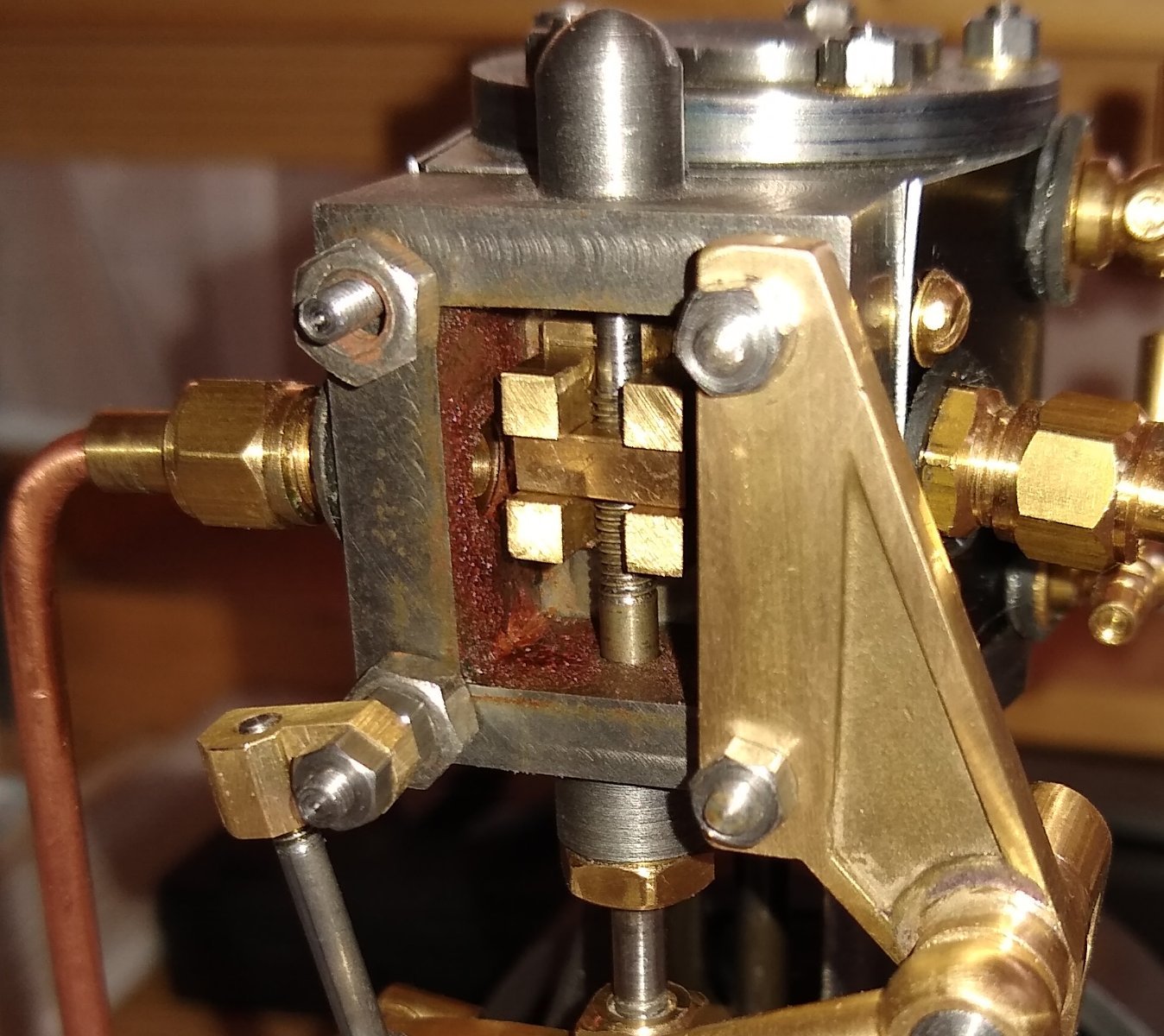
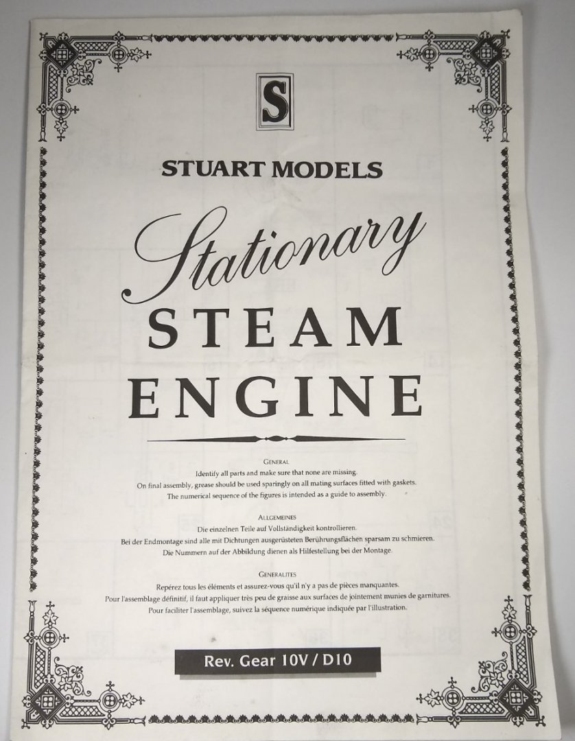
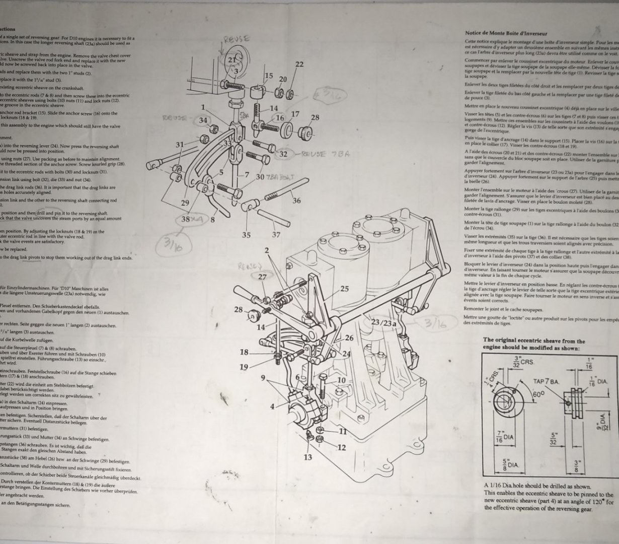
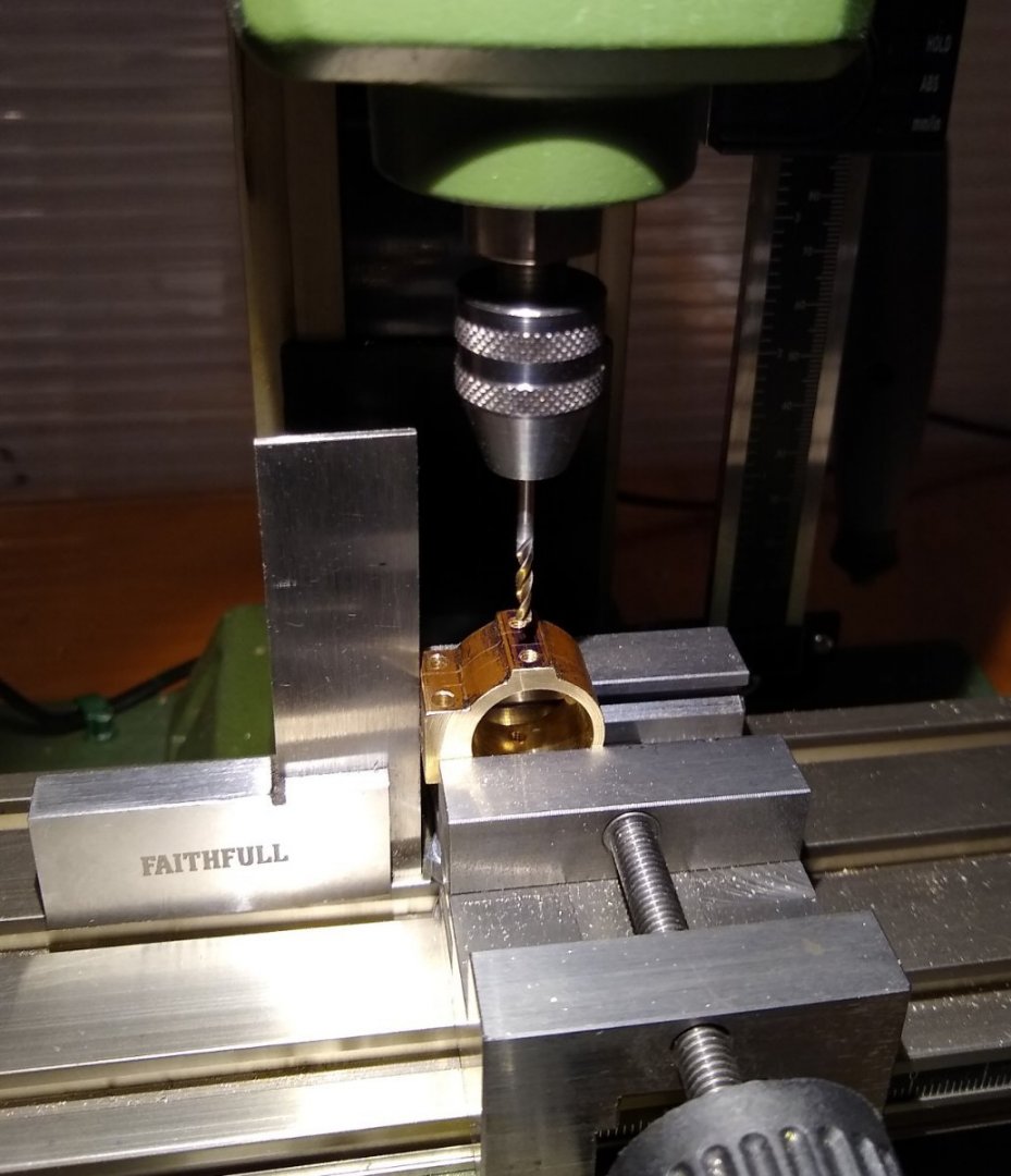
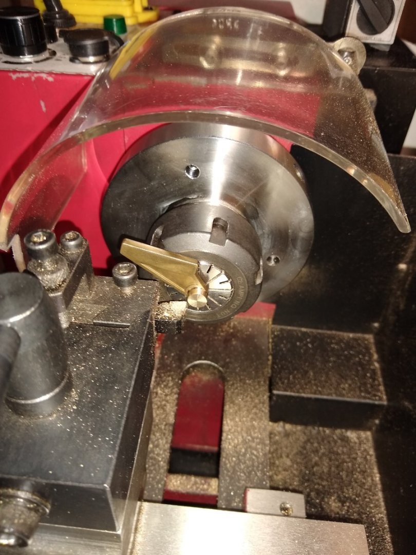
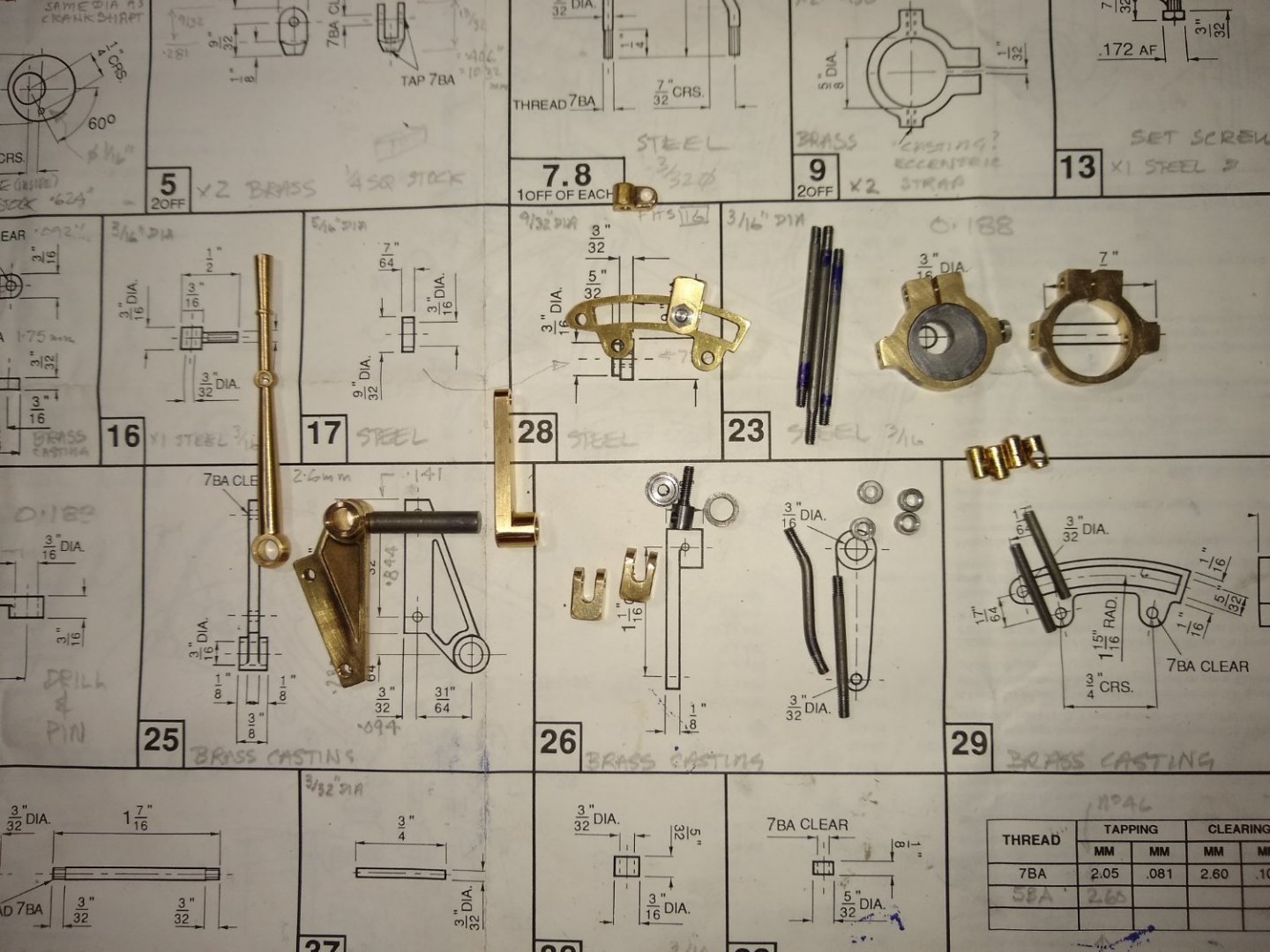
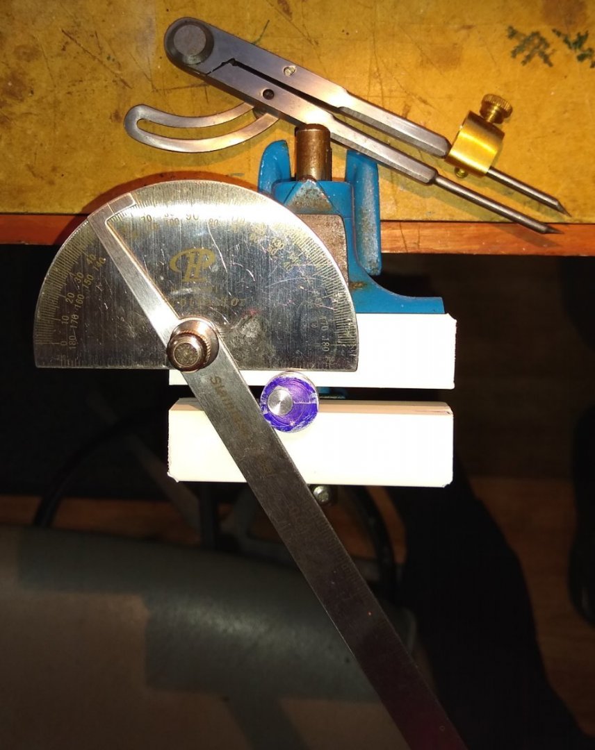
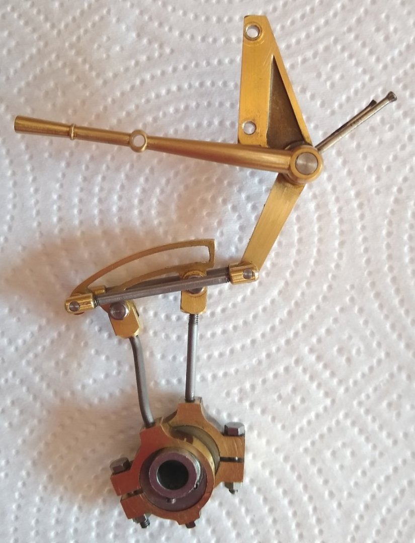
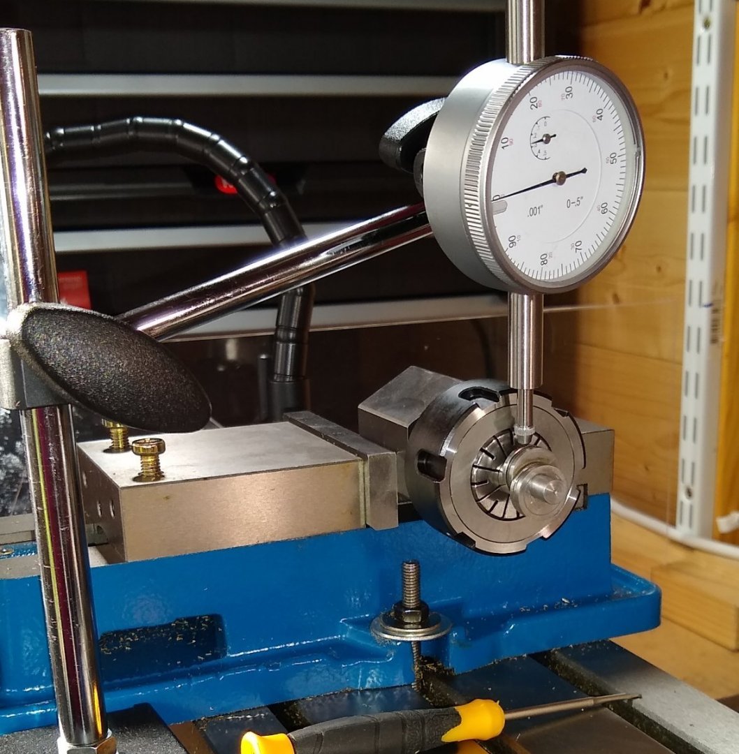
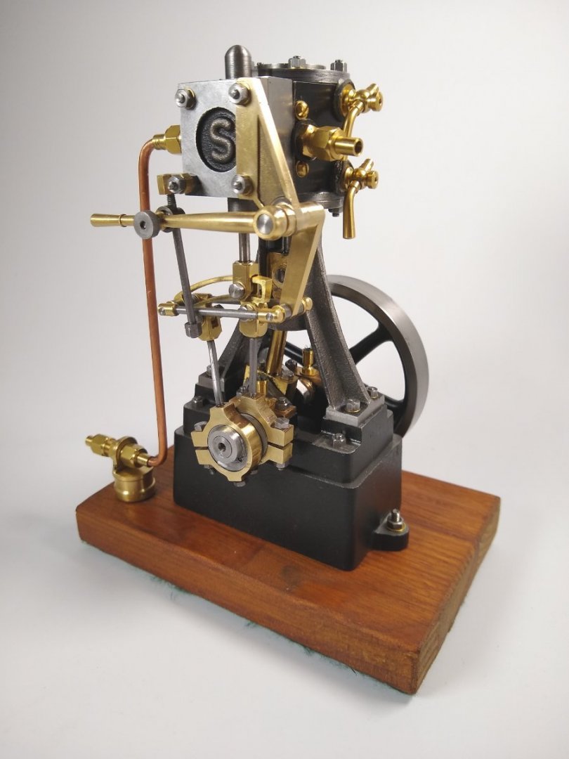
Hi all, Stuart 10V Steam Engine - Reversing Gear (RG) update. The RG is used in marine applications for changing the rotational direction of the propeller shaft. I finished and test ran the RG, using compressed air, about a week ago - it performed fine. Following, are some snippets and thoughts/puzzles/errors I encountered during the build. Firstly, as usual, the Stuart drawing/instructions are a single fold-out large sheet, and it uses Imperial sizes so I will tend to stick with those during this post. Below, the exploded views and an indication of the succinct instructions (in English, German and French). The 10V as it stood before the RG was added. Some parts of the engine were removed and modified to work with the RG. Below, a typical part being drilled. In this case the Eccentric Strop(s) that link to the valve rod. The brass part is sliced in two once all the machining is completed, resulting in two Strops. The Expansion Link with a Rod Head about to be machined out of 1/4" square brass stock. The finished Rod Head fitted to the Expansion Link. The Expansion Link is used to switch between Forward and Reverse rotation of the flywheel by locking the Rod Head at either end of the curved, rectangular slot.. There were many holes requiring tapping, mostly 7BA (British Association), which has an O/D of 0.081". Here, I am using the drill chuck (loosely closed) to maintain a straight tapping action, with the tap being held in a pin vice. I could turn the tap by hand since the material was brass, mild steel was a bit more challenging for me and the tap. Below, the four Drag Link brass Ends part way through manufacture. It was important that the the tapped holes and the cross-holes were made square. The Drag Linkage. It did turn out very square. Six months ago it wouldn't have been as good but I'm slowly getting better, and also remembering the skills I learned decades ago. Below is the Anchor Rod Bracket being turned. This part attaches the whole RG assembly to the top half of the engine. A collection of all the parts that needed making. Next was to assemble them all and in a fashion that allowed smooth running...easier than it sounds 😉 Below, one of the two Eccentric Sheaves being marked out to accept a 1/16" pin that passes though it and the other Sheave, locking them together at 120 degrees. The two Sheaves (similar to cams) control the valve movement (ie when pressure enters/exits the Valve Chest) and so controls the piston/flywheel forward and reverse rotation. Test assembly of the parts. Two 1/16" panel pins were (finally) used to lock the Reversing Lever and Connecting Rod in position. I had initially used thread lock liquid since it allowed positional 'tweaking'. Below, the RG assembly attached to the engine. The Valve Chest cover is removed to observe the valve movement (- small brass square shaped object in the chest middle). For pressure testing I fitted a clear Perspex square to seal off the chest whilst allowing me to observe the valve movement. Ouch!...when I first removed the Valve Chest cover I was confronted by rust. I had been meticulously oiling all the moving parts but had forgotten about the inside of the valve chest. I was impressed by how easily the rust had formed, but bare mild steel + air + moisture always leads to one thing. After faffing about for a couple of days trying unsuccessfully to get the valve timing set correctly to allow smooth running in Forward and Reverse I started to re-examine the parts, particularly the Eccentric Sheave spacing (120 degrees). So I cobbled together a test set up on the mill - finding the high point of the first Eccentric then zero'ing the dial indicator, then rotating the hexagon collet block by two flats (120 degrees) and measuring the second Sheave's high point ...turns out they were only 0.010" apart, if that...well within my acceptable tolerance. That 10 thou would directly translate to the valve movement ie the there would only be 10 thou difference between forward and reverse port openings. Eventually, I got the valve timing sorted. The 10V now runs extremely smoothly in Forward and slightly less smoothly in Reverse but close enough for Jazz. Below, the finished Stuart 10V with Reversing Gear. The Reversing Gear, although a smaller project than the 10V itself, there was more time spent on 'set up'. Lots of new things learned and the time passed enjoyably and quickly, which is what model building is all about 🙂 All the best, Richard


- 55 replies
-
- 22
-

-

-

-
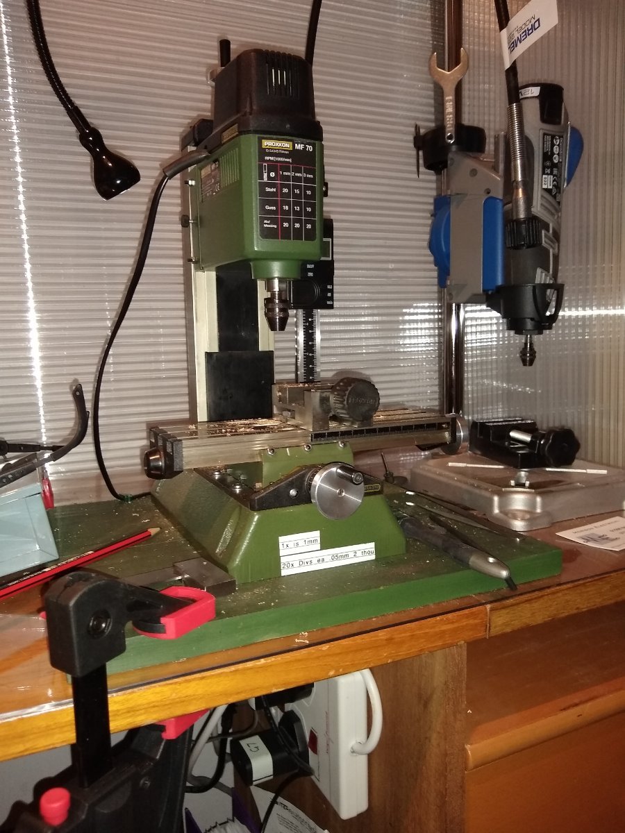
Hi juddson, I've had a Proxxon MF70 for a couple of years or so. It was bought for working on model ships and very light metal work, and it does both fine. I tend to now use it mostly for small metal parts for static steam engines. You'll need a good range of Proxxon accessories to make best use of it. It is very quick to set up and use, although small cuts can take a while. On metal, I usually only take 0.125mm (5 thou") cuts at time, 0.250mm if I'm feeling adventurous. It is very compact. I have screwed it to a permanent wooden base which is then clamped to the table. It is high speed (and therefore noisy) so I tend to wear ear defenders when using it. Regards, Richard

-
Artesania Latina 1:50 Dallas 1815 Revenue Cutter
Rik Thistle replied to Capt Mongo's topic in Wood ship model kits
Capt, I do have the plans, as I believe you do also. I also have most of the wood that surrounded the bulkheads before they were pressed/cut out. The wood is missing Bulkhead 9 towards the far right of the picture below., but it might be enough to get the show on the road. Regards, Richard PS: The pic looks like it has some barrel distortion but is actually like that in reality. I seem to remember the wood and shapes were fairly roughly marked out and nowhere near as accurate as modern kits.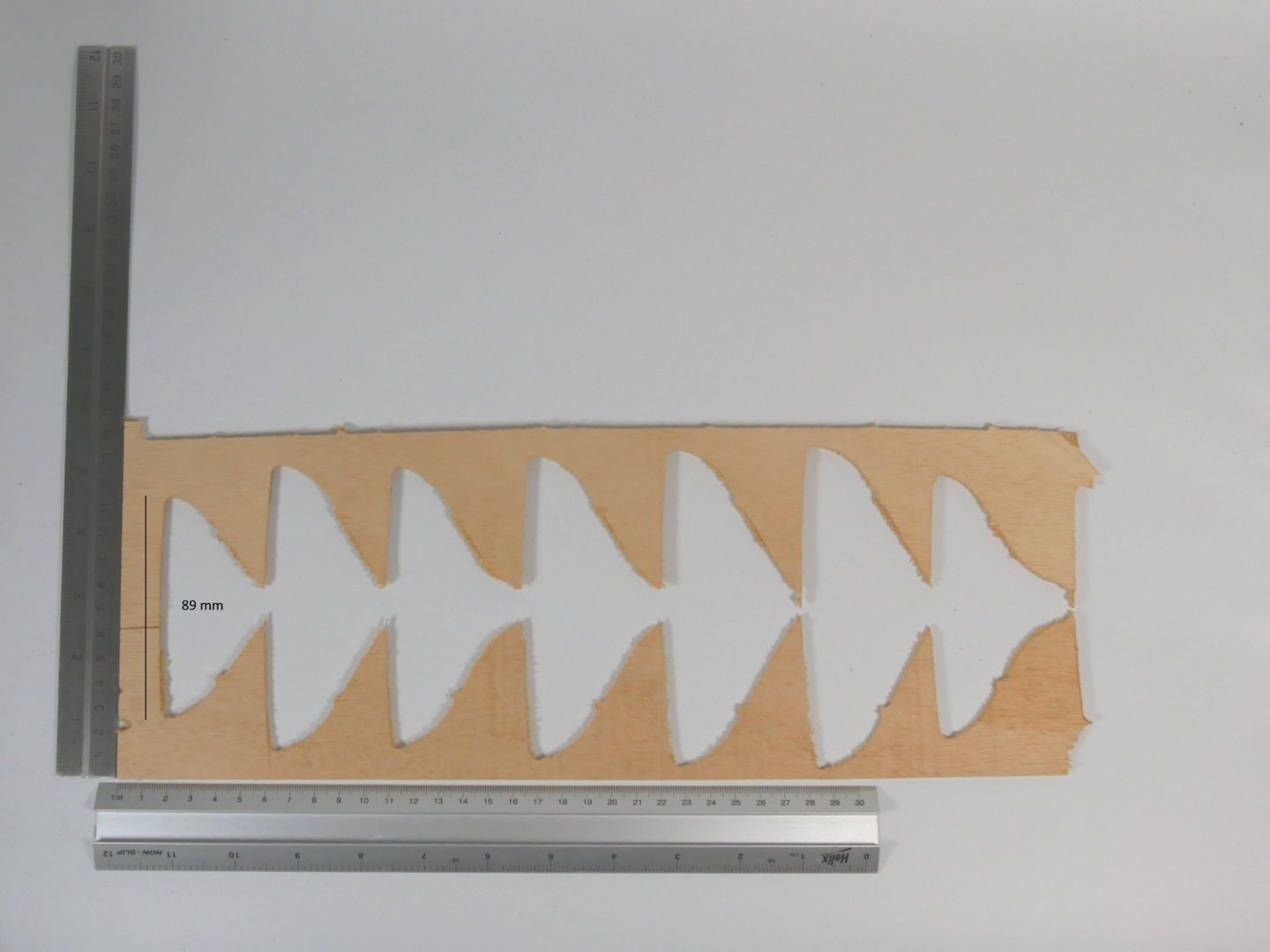
-
Artesania Latina 1:50 Dallas 1815 Revenue Cutter
Rik Thistle replied to Capt Mongo's topic in Wood ship model kits
Capt, I finished this ship a little while ago. IIRC, the plans 'might' give the bulhead shapes to scale. I think I still have the plans, somewhere. I'll have a look and get back to you, hopefully within a couple of days. Richard -
2nd hand items
Rik Thistle replied to Mary-Ann Cockburn's topic in Modeling tools and Workshop Equipment
Mary-Ann, The ship modelling club at Anstruther (as linked above) sounds like a good first bet. I believe it is linked to the Scottish Fisheries Museum. They have 25 members and seem quite active. Maybe drop them an email. As has already been said ,I'm quite sure your relative would be happy that their tools etc to go to people with a similar mind set. I hope it all works out OK for you. Regards, Richard -
Hi Glenn, through the slot Yes, it could be that; I'm just not 100% sure. I'm beginning to kinda convince myself that the J blocks are attached as pairs. Your comment made me look through the Plan Sheets 7, 8 & 9 (rigging etc) and that implies they are in pairs supsended from the two middle crosstree arms. But my ... Q4 - why would the block (and it's partner on the far side?) be at a different height? .... from Post #81 still stands I can't figure out why the blocks are shown at different heights. Regards, Richard
-
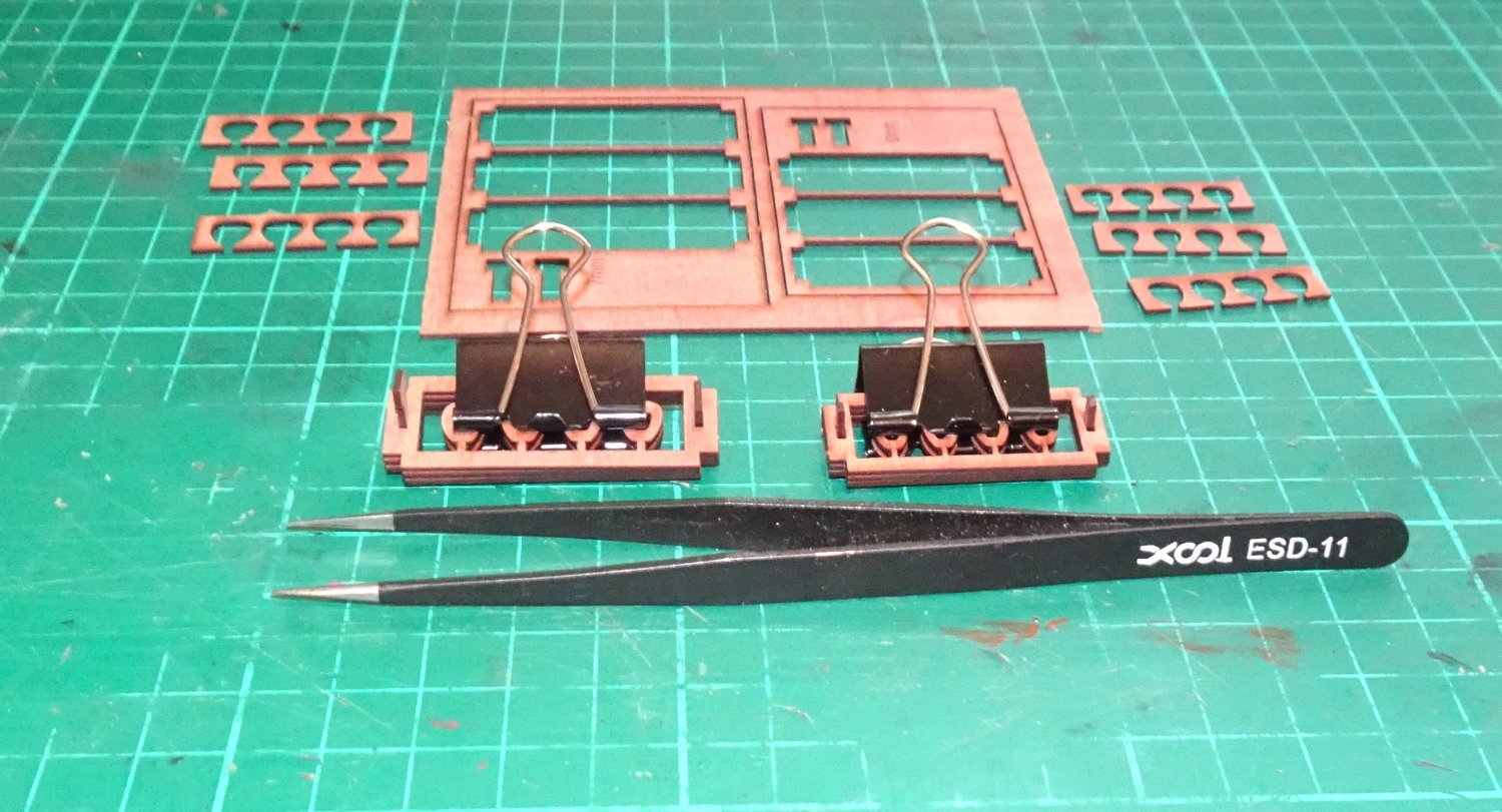
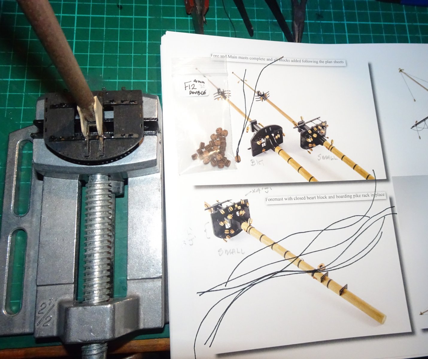
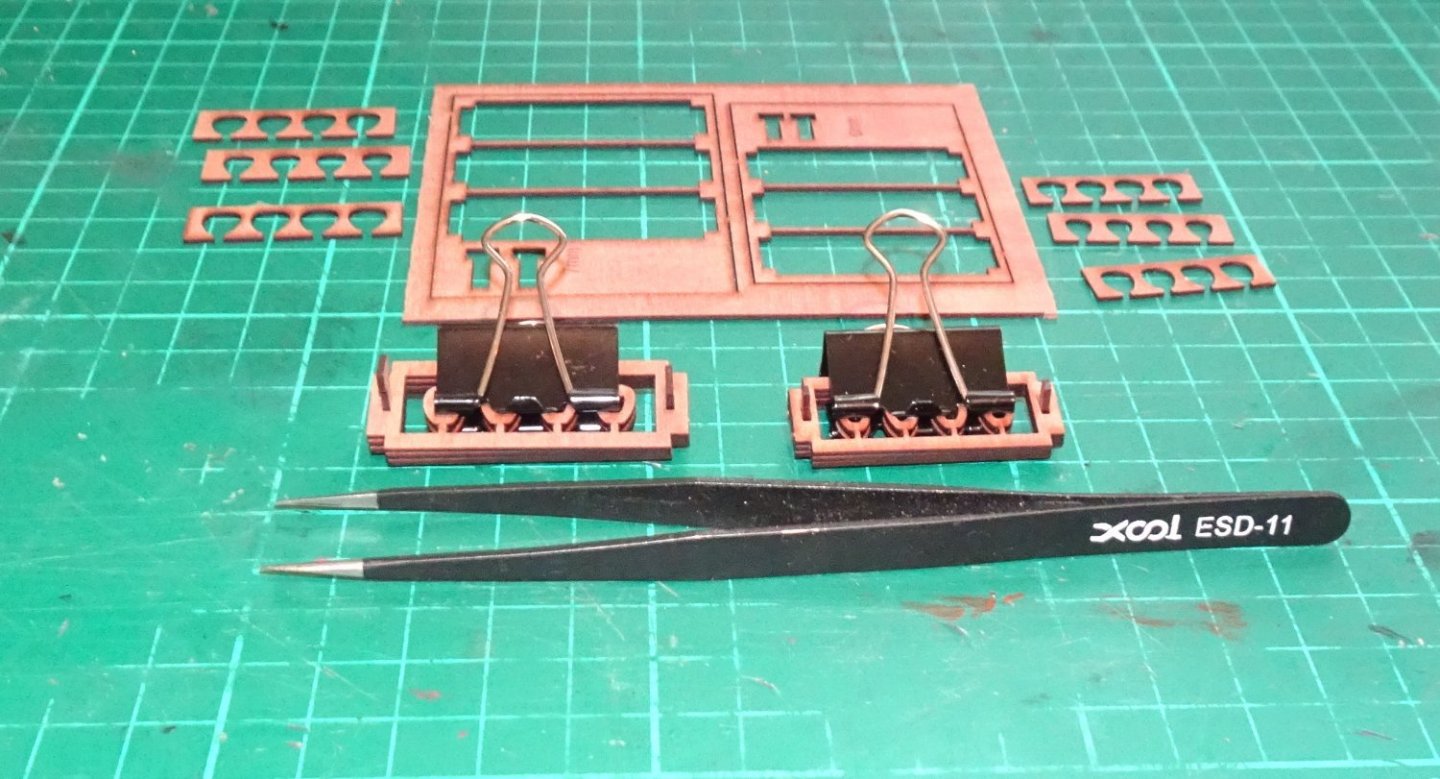
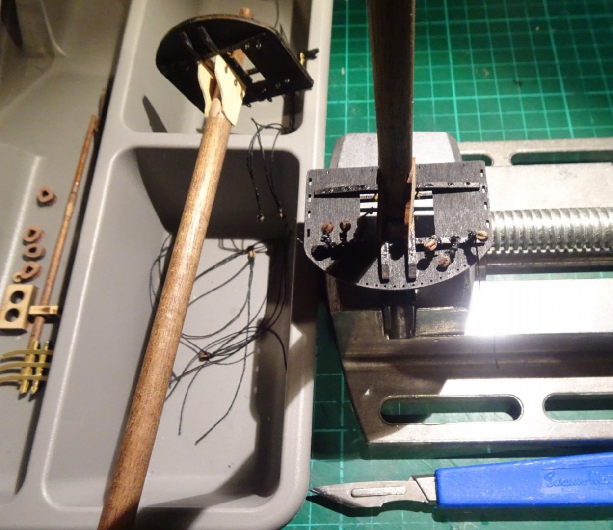
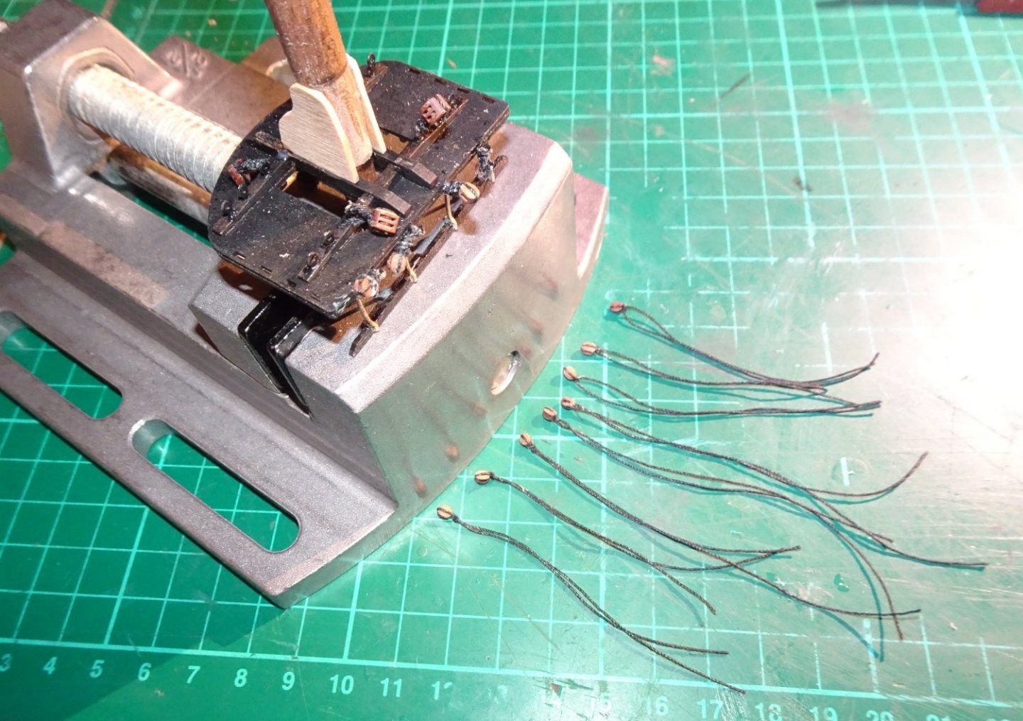
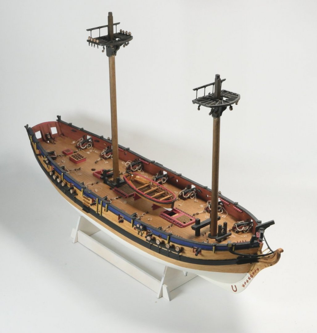
Hi all, A small update on where I am, mostly regarding the Main and Fore masts. Below, gluing together the 7mm and 6mm closed hearts for the topmast stays. Below, The two masts were gingerly held in a lightweight vice acting as a 3rd hand. Below, preparing the rope lengths for the some of the single J blocks (item F10). Somehow the double L blocks (F12) sneaked in to the picture. OK, that is the J blocks now attached to their ropes and lined up ready to be attached to the Main Top and Fore Top. The double L blocks had already been fitted. Some black paint had already been applied to ease the final painting with masking tape. The Main Top with most of it's blocks etc attached. Both masts testing their new home. There is still a heck of a lot to do to get the masts completely finished, but now that we are in the middle of (a mild, so far) winter here in Scotland I hope to devote more time to Flirt. All for now. Regards, Richard


-
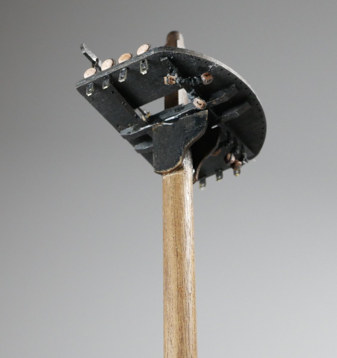
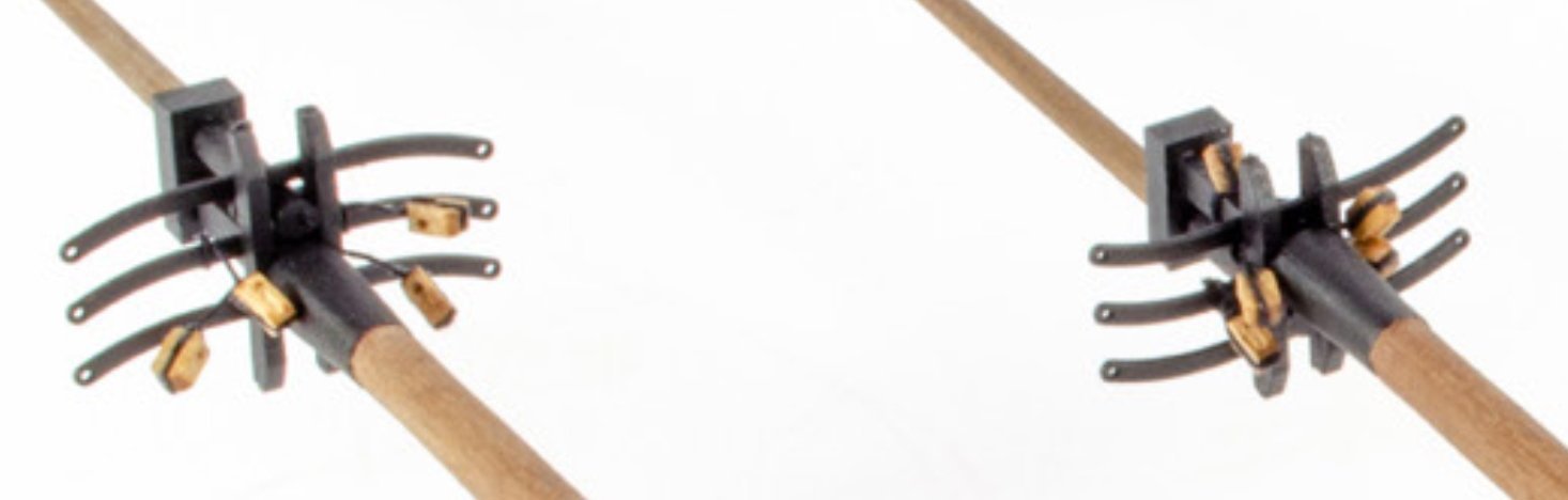
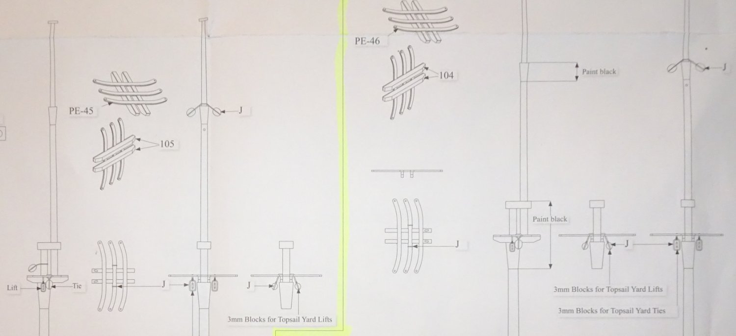
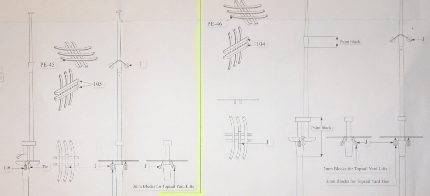
Hi all, I have a bit of uncertainty regarding the number, type and attachment point of the Topmast Crosstrees' blocks. I wonder if anyone would be kind enough to point me in the right direction. On the image below (from pg 52 of the Manual) it shows the larger Main Topmast Crosstree (left) and the smaller Fore Topmast Crosstree (right) On the left side of the pic above I see 4x 'J' blocks - the uppermost two blocks I can see are attached to the middle legs of the Crosstree (as the drawing below shows) , but the bottom two blocks seem to be attached to something near the mast itself? Q1- where/how are the bottom two blocks attached. .... and on the right side I see 4x 'J' blocks - two are attached to the middle legs of the Crosstree, and the other two as per on the left side? Q2 - See Q1.... (Note: I also see a fifth block but I believe that is attached to the 3mm square section of the mast?) Below is a crop from Plan Sheet 5 (Fore and Main mast). This time, the left side shows the Fore mast and the right side shows the Main mast. From above ... on the left side of the crop ....ah, as I write this I may see part of the answer....there are a pair of 'J' blocks hanging from each of the middle legs of the Crosstree. Q3 - are the J blocks suspended in pairs? On the right side above, I see a block suspended at a different height (in the view where it mentions 'Paint black'). Q4 - why would the block (and it's partner on the far side?) be at a different height? I've been staring at this block arrangement for about two weeks on and off and getting nowhere, so hopefully someone here can put me out of my mysery 😉 I'm sure the answer will be straightforward, like a crossword puzzle I've been looking at too long. Regards, Richard

-
FlyingFish, The final pic, of you standing at the door, is a real keeper. I'm amazed at how some people have the persistance and skills to keep hammering away at the all superbly crafted fine details till the project is complete. Awfully well done. Richard
-
Andrew, Thank you, yes "Nisha" is diminutive, but I think there was a bit of distortion in that shot as it makes her look tiny. Picture below against a 12inch rule. Widest part of her beam will be just under 3 inches when finished. I didn't have a mental picture of her size till now. Since bench/shelf/display room is an issue in my study the relatively smaller size of Nisha makes her more attractive, and she is still on the same scale as Vanguard's other models (1:64). Anyway, she's coming together very well in your build. Richard
- 206 replies
-
- 3
-
-
-
- Vanguard Models
- Brixham trawler
- (and 2 more)
-
Welfalck, What a great selection of books on that website ... https://www.camdenmin.co.uk/ Thanks for the heads-up. Richard
-
Alan, If the historical interludes are boring please let me know and I will desist. I find this area hugely interesting and can get a bit out of hand. Personally, I find the historical pictures and background stories very interesting indeed. But I can't speak for everyone. Richard
- 92 replies
-
- 11
-
-
Steve, She looks fine in the pic, but maybe you are finding some 2nd planks don't sit flush next to their neighbours? IIRC, I had a bit of that ...I locally unglued those areas, slipped a thin section of sanded plank/shim underneath the 'sunken' planks to push the misaligned planks out to lie flush with the adjacent plank. Then a final sanding and all was resonably flat and plenty good enough. Richard
-
Tim, That's exceptionally neat looking.... Amati would be happy to use it for box art I suspect. Looking forward to seeing the remaing parts added, and then finished Fifie sitting next to the trees, or maybe some water if there's any nearby. 😉 Well done, Richard
- 79 replies
-
- 2
-
-
- Fifie
- Victory Models
- (and 1 more)
-
The fleet leaving Eyemouth Definitley a good day for hanging out the washing! Richard
-
After a LOT of sanding, 🙂 Yup, I know the feeling. I think some of my first planking was sanded almost paper thin in places and I was worried that the 2nd planking would have nothing substantial to hang on to.... but it turned out OK. I think the reason mine was paper thin was to compensate for not sanding the bulkheads correctly in the first place. On my next hull I will put a lot more effort into getting the bulkhead contours correct rather than charging through that part of the build (...he says). Anyway, she's definitely starting to look like a Fifie! Richard
-
I think the shape created by your first planking layer looks perfectly fine. And, yes, filling and sanding is your friend - it certainly was mine 😉 You'll be very pleasantly surprised by how good she turns out once all the planking is done and a layer of paint added. Richard
-
Off on a slight tangent but it does involve photography and the 'talent' is an interesting, ancient subject ..... https://www.model-engineer.co.uk/forums/postings.asp?th=174972 It involves the 'Antikythera Mechanism Research Project' - the 2.000 yr old lump of brass that was found on the sea bed, and turned out to be a very sophisticated lunar calendar. X-ray photography was used on the 'lump' to see inside. Now some posters are starting to ask if the way the photography was done may be misleading the Project team members. The discussion really starts to warm up on pg 5 (IIRC) when one of the Project team joins the discussion. Richard
-
Proxxon compound table KT 70
Rik Thistle replied to Dziadeczek's topic in Modeling tools and Workshop Equipment
I have the 'Proxxon PM40 precision steel vice' that Tony mentions, on my MF70 micro milling machine. It seems quite precise and is extremely easy to use - a large plastic thumbwheel tightens the work piece in the vice jaws. Occasionally I wished the jaws would open another 2 or 3 mm but no big deal. It is bolted to the table.... the bolts can be a little fiddly to get in to place but again, not a big issue. I also have a precision toolmakers insert vice (for a Sieg SX2P mill) that Wefalk mentioned. It is very easy to deploy, fitting inside the jaws of the larger vice already fitted to the table. It's minor drawback is that a separate tool (Allen key) is required to tighten it's jaws. Both vices suit the type of machine they are designed for. Thomas, for Proxxon equipment I wouldn't hesitate to get the Proxxon PM40, assuming it fits your table. Richard -
not that there is any rush. Steve, enjoy it while it lasts 😉 ... you'll be surprised how quickly the time passes. Planking, I find, requires a number of skills... - correctly curving the surfaces/bulkheads the planks will lie on - cutting the planks to the correct shape - bending them - preparing good rabbets - getting the planks to follow the structure underneath - and not least, making the planks stick in place I'm sure there are other steps I've missed. I'm still learning about all these steps. Some I'm better at than others. Some still pretty poor. But it's good fun learning...if it was too easy then there would be no challenge and satisfaction when done. You're doing good. Richard
-
Where timberheads are fitted with a rail, they are adjoined with a temporary beam which makes sure the spacings are correct That's clever 😉 Richard
- 36 replies
-
- 2
-
-
- vanguard models
- Erycina
- (and 2 more)
-
Mark, I don't have a YT channel, Facebook account etc, or plan to. And I can understand MSW not allowing even a 10 sec video to be directly hosted on this website...bandwith, storage etc. But, I have got the reversing geat kit for the engine so will be adding more pics to the build over the next 12 mths. Richard