HOLIDAY DONATION DRIVE - SUPPORT MSW - DO YOUR PART TO KEEP THIS GREAT FORUM GOING! (Only 75 donations so far out of 49,000 members - C'mon guys!)
×


AnobiumPunctatum
-
Posts
1,281 -
Joined
-
Last visited
Content Type
Profiles
Forums
Gallery
Events
Everything posted by AnobiumPunctatum
-
Chuck, yes that's exactly what I am missing. This part makes me in the moment some problems during the reconstruction of the Alert. Do you have some otehr pictures of this cutter model which you can share?
-
Chuck, I've a question to your planking. If I look at the planking sheme of your cutter, I found a vertical triangle under the counter. As far as I understand will the planks end before that. You've also drawn this but you did not use this in the praxis. Is there a special reason or is it a simplification? Your planking looks really brilliant.
-
Jürgen, what kind of timber do you use for the planking? The contrast to the darker swiss pear looks really great
-
Lee, last year as I started with the project, I had the same idea. But I had problems to match the dimensions he has given in the first part of the book with the drawings. At this point I started to use a simplified frame model. Then I started my build but was not happy. His line drawing differs from the original drawing which you can find on the NMM Homepage. And I couldn't find the reasons. In September I bought the original drawing and started again ... the rest of the story you know. Meanwhile it makes a lot of fun to search and compare the different original drawings. I think I will do the same steps on the next models I like to build also. There is also nothing wrong with your approach. I will follow your log with great interest.
-
I am sure, that the frame desing of Goodwin is not the original design. Most of the original cutter drawings only Show double Frames. Cheerful instead shows only single frames. That is one reason why I like to build my model with a stylized frame design
-
Druxey, is it right that the fashion pieces and the transom would notched for the planks at the stern?
-
Druxey, thank you very much. This shows what I am searching. Now I have an idea how to continue.
-
Thanks all for your help. @Druxey. I know the drawing. Dbut the drawing does not really help. Has the keel only a wing transom, or how is this part of the ship designed? How will the planks of the lower stern be fitted to the fashion piece?
-
Lee, please send me a PM with your mail address. I'll send you a copy of my first keel drawing. Be aware it's in scale 1/48. The new one will not work with Goodwins reconstruction.
-
Antony, thanks for searching. If I don't find another solution I will build this part with basswood first and than look how I can anrrange the frames. My frame design is stylized so I have different options. But I hope that one of the more experiencend modeler can help.
-
Hallo Lee, welcome on board. I am also working on a model of this small cutter. Have a look in my signature, there you find a link to my build or in the moment better drawing log. Have a look at page 4 to find my Interpretation of the keel, deadwood and so on. Perhaps it's helpful
-
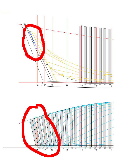
It's time to show a short update of the frameing. The frames and the fore cant frames are finished. In the moment I work on the after cants. There I have a big problem, because I don't understand how the construction really works. All drawings I found do not show any details. Is it right, that the fashion piece has the same angle as the last cant frame? Perhaps someone can help me out, to understand this detail right.

-
Normally oil color will harden in a week or two
-
Really nice progress, Jürgen. As you know, I am a great freind of oil colors for painting the wale black.
-
Mobbsie, now it's clear, but I don't have any idea why the author of the drawings choose this solution. It is in my knowledge not common. I've had a short look at the prototype build of Mike at MSB, but could not find a picture of this area. I would suggest to build frame 12 and check if it is on top of the rabbet ot your model.
- 255 replies
-
- 1
-

-
- granado
- bomb ketch
- (and 2 more)
-
Wow, your model becomes nicer and nicer. I like your precise work very much.
-
Mobbsie, thanks for your explanation. But I can't follow you. If I have a look at the original drawing at the NMM (see here) the rabbet doesn't have a curved line. You're sure that you do not misinterpret a line on your drawing?
- 255 replies
-
- 1
-
-
- granado
- bomb ketch
- (and 2 more)
-
Thanks very much for your offer Anthony. Surely you can post them, if you like. Is it possible to save the drawings in DXF-Format? This will make things much easier.
-
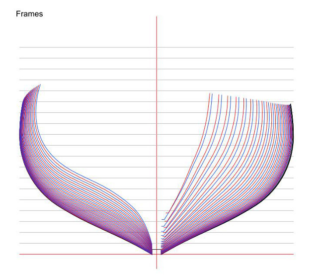
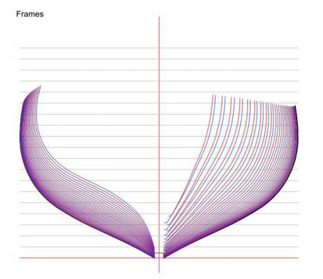
Slowly, in the moment I am drawing all frames. The parallel frames will be finished this evening, then I start drawing the 21 cant frames.
-
Ben, really nice progress.
-
I think you have a nw hobby, Jürgen. Sanding, sanding
-
Mobbsie, the curve of your keel rabbet confuses me. I thought that it is nearly a straight line midships. Your frame is looking nice.
- 255 replies
-
- 1
-
-
- granado
- bomb ketch
- (and 2 more)
-
Really wonderful and precise work.
-
Welcome to the dark side and a lot of fun with your build