

.jpg.2c2c29e54623bd7b752bc2cdab599665.jpg)
Danstream
-
Posts
756 -
Joined
-
Last visited
Content Type
Profiles
Forums
Gallery
Events
Posts posted by Danstream
-
-
On 1/7/2026 at 10:54 PM, GrandpaPhil said:
Very nicely done!
Thank you Phil for your nice comment!
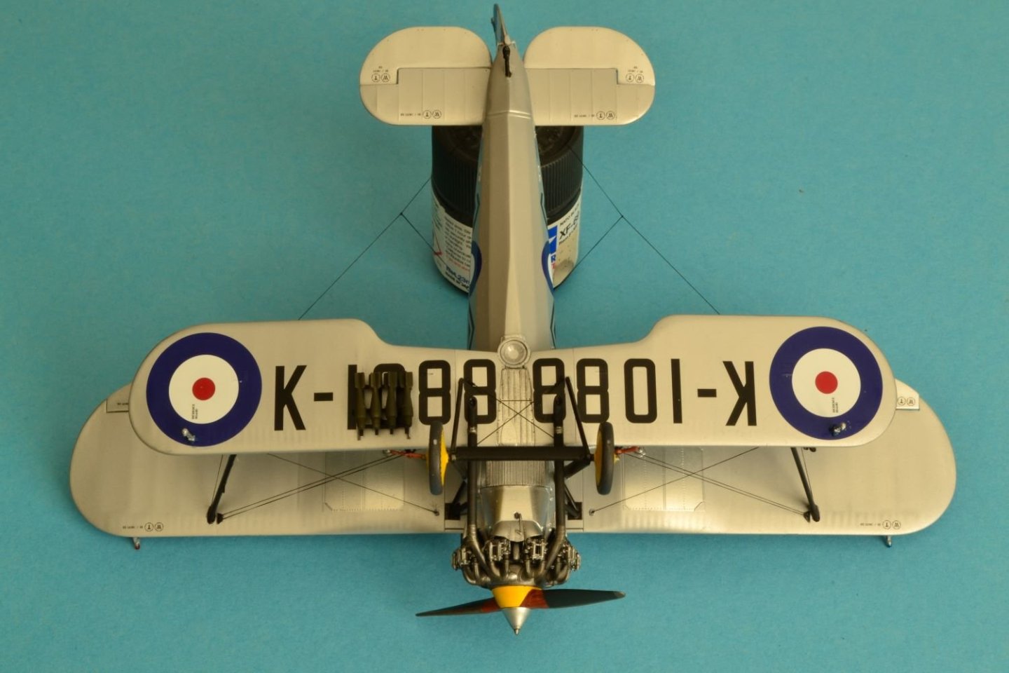
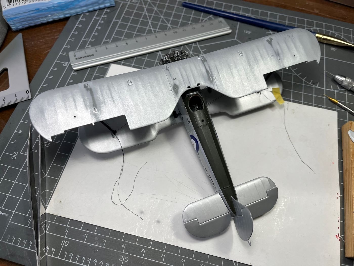
On 1/8/2026 at 10:04 PM, gsdpic said:Wow, excellent build. I am even more impressed now that I understand the relatively small size of the model, thanks to the upside down picture with the Tamiya paint jar under the tail, and of course the picture of your photography set up.
Thank you Gary! Yes, the size of this model is quite minuscule although 1:48 scale. The biplanes of that era were not large in comparison with more modern stuff. Sometimes I struggled to get around the model especially when working between the assembled wings.
Best regards,
Dan
- GrandpaPhil, Canute, king derelict and 3 others
-
 6
6
-
-
5 hours ago, king derelict said:
Absolutely beautiful Bulldog Dan. The finish is immaculate and realistic too. Great work.
after five days stuck in Amsterdam because of the snow, flights cancelled at Schiphol and NS trains cancelled for days Im finally on my way to Berlin where the weather is also due to deteriorate. I got to know Amsterdam a bit better thoughThank you Alan for your nice comments about my build.
I am sorry for your misadventure at Schiphol. I live not far from there and I could have brought you to a huge hobby shop nearby Schiphol to spend some time (and money perhaps), although visiting Amsterdam is much more interesting from artistic and historical point of view.
Good luck for the continuation of your trip,
cheers,
Dan
- Canute, Jack12477 and Old Collingwood
-
3
-
19 hours ago, AJohnson said:
Brilliant work Daniele!
A great looking model, you should be proud!Thank you a lot Andrew for your nice comments. I appreciate them!
4 hours ago, Canute said:Nicely done, Daniele.
New Airfix makes some nice kits, for sure.
Thank you Ken, I am glad that you like my work. Yes, Airfix is very good.
4 hours ago, BLACK VIKING said:Wow that's a stunning build brilliant job
Wow Martyn, thanks for your great comment.
Best regards,
Dan
- Jack12477, Old Collingwood, Canute and 1 other
-
4
-
19 hours ago, amateur said:
Not only the model is superb, also the pictures of it. What is your fotostudio setup?
Than you Jan for your kind comment which I appreciate greatly. I am also happy that you commented positively the pictures. About the setup, I have to admit that my setup is very basic and simple as shown in the picture below. I just use what I had in the house. In the past, I was used to use two 5000K table lamps, but recently I like to use natural light diffused by the window light curtains. I hope that my basic approach is not disappointing anyone.
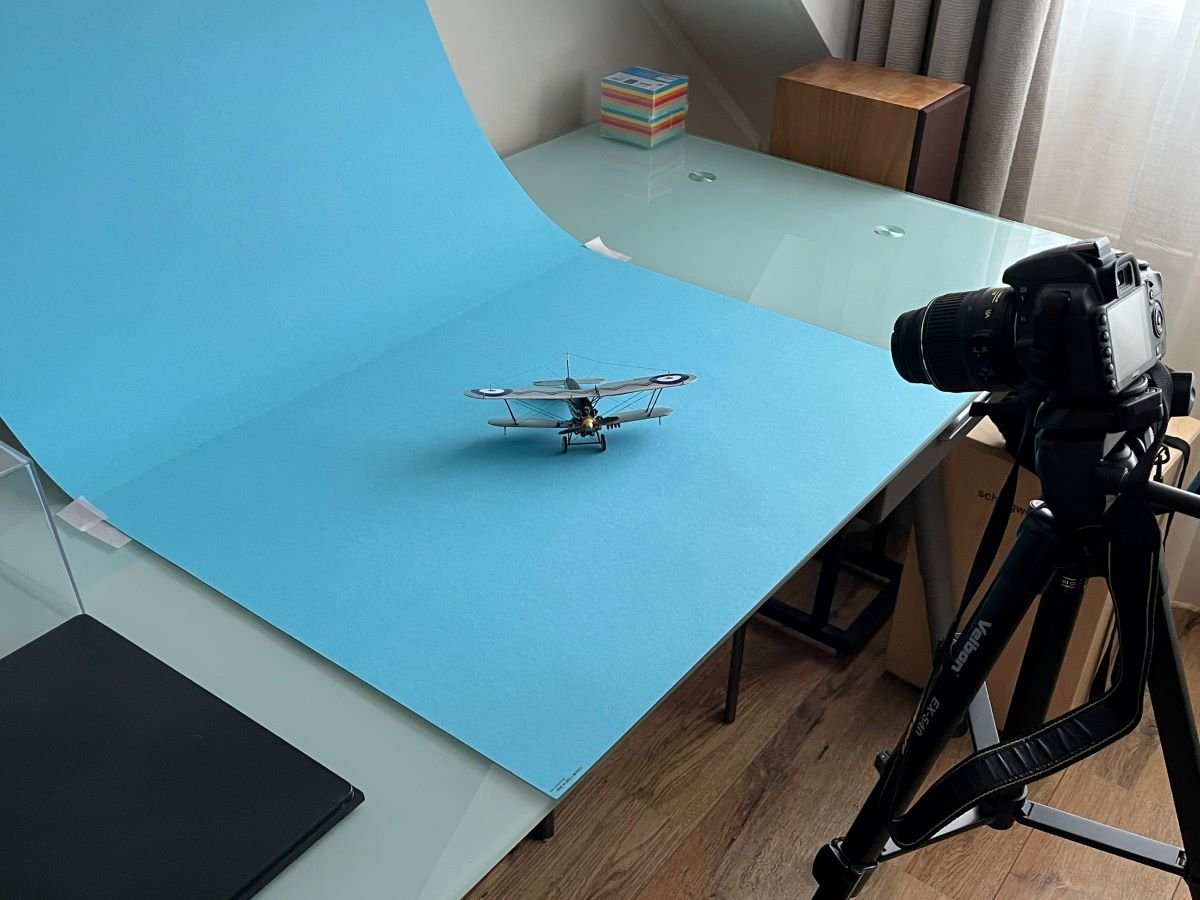
I always tend to stay as basic as possible in many of my activities and step up with equipment only when necessary. Of course, the drawback of this simple setup is that you have to wait for a bit of sunshine and this is sometimes a bit of a difficulty in winter here in Holland 😉. What I do to get best results is to use a very small diaphragm aperture to get the maximum depth of field and use the maximum tele lens setting to flatten the perspective. Both of these things call for extremely long exposure times which require clearly the use of a tripod. For triggering, I use a timer, so I don't need to touch the camera to shoot a picture. In addition, I very often take several 'bracketed' under/over exposed shots and select the one that I like best.
I hope you like my, perhaps, too long explanation,
warmest greetings,
Dan
-
21 hours ago, ccoyle said:
Wow! Looks great!
Thank you Chris!
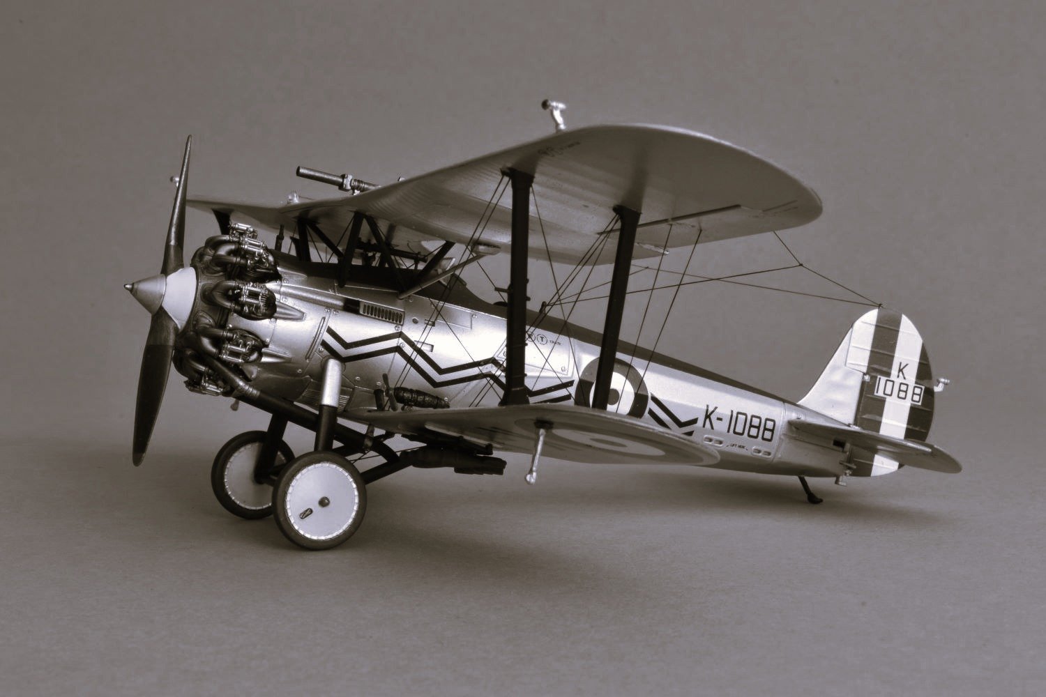
21 hours ago, DocRob said:Fantastic result, you achieved a little gem, Daniele. I especially like the slightly toned black and white shot.
Thank you Rob for your positive comment. I also like the B&W shot version, I often play with that.
19 hours ago, yvesvidal said:Amazing !!!! I can't believe this is an AIRFIX kit. They have really improved recently.
You turn that model into a little marvel, honestly.
Thank you Yves for your enthusiastic comments about my model! Yes, the latest Airfix kits are getting really nice.
Best regards,
Daniele
- DocRob, Jack12477, Old Collingwood and 2 others
-
5
-
-
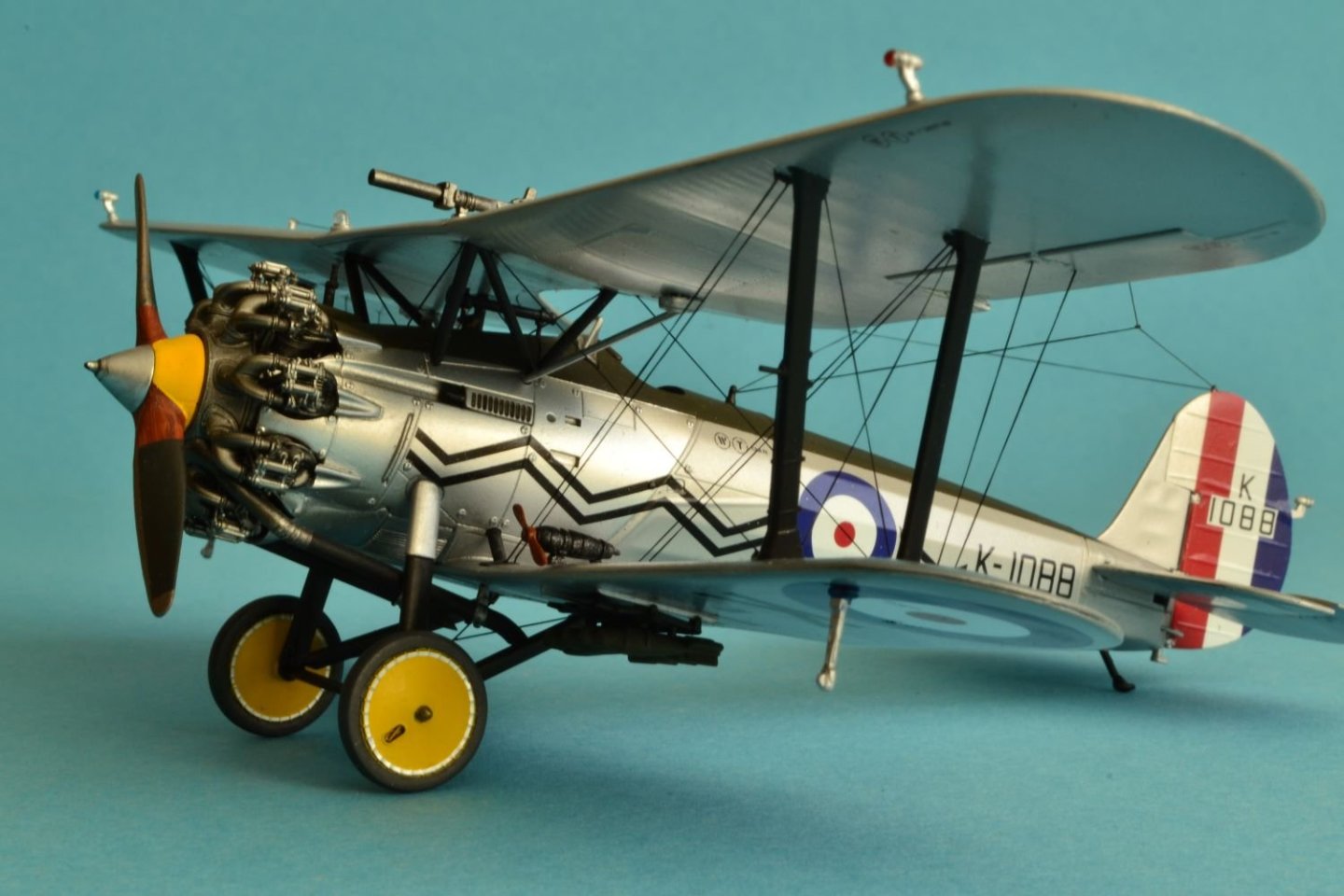
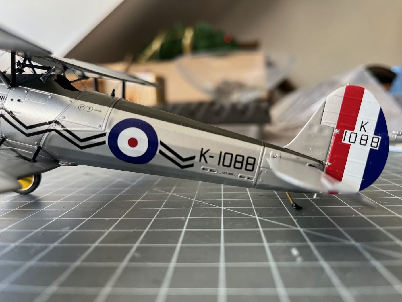
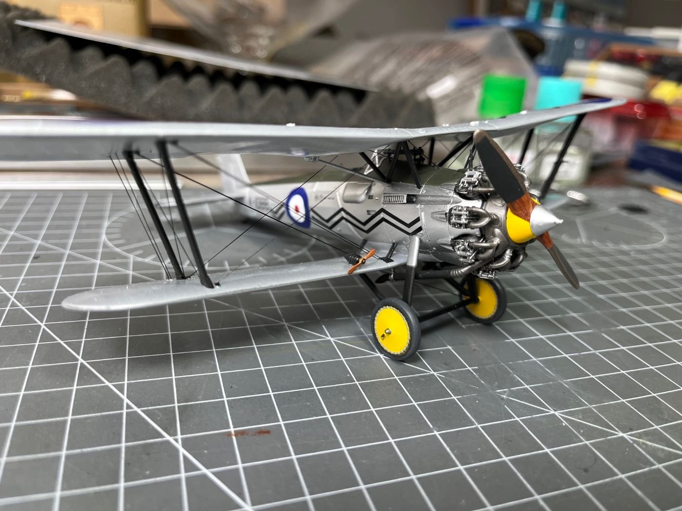
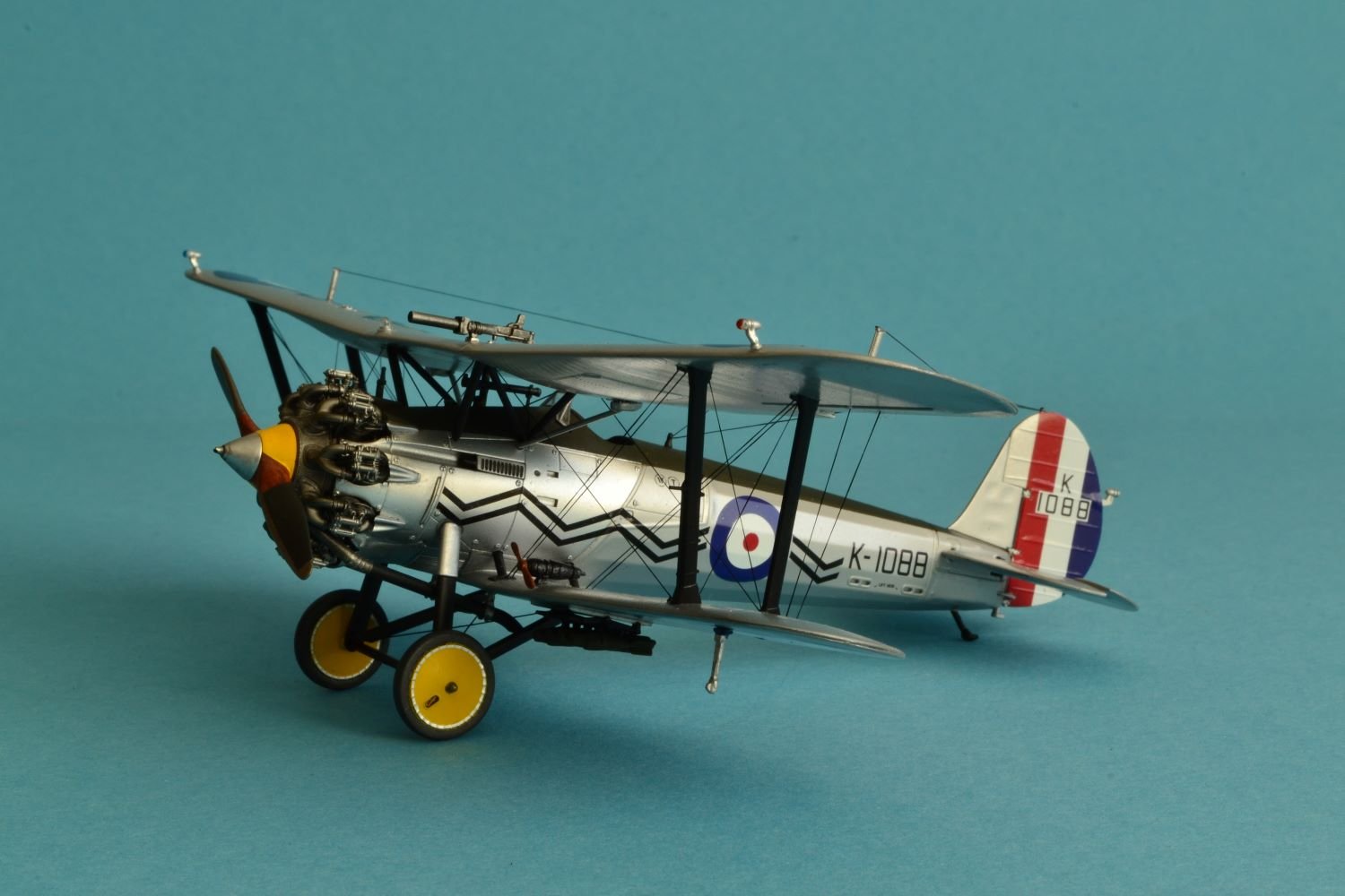
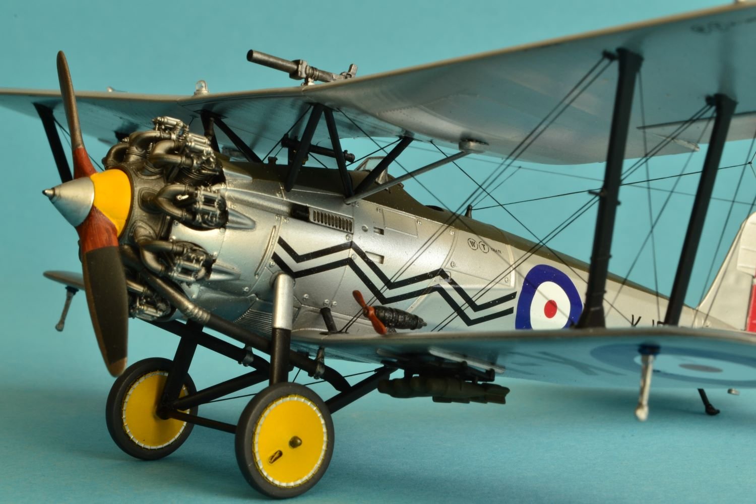
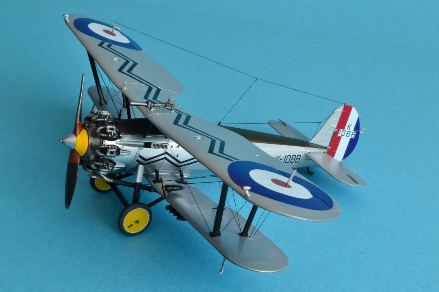
Dear all, after a long absence, I am back with the final pictures of my completed model.
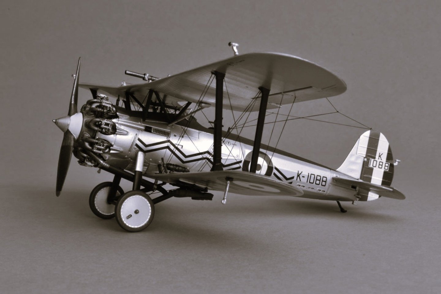
Bristol Bulldog MK II
No.17 Squadron, Upavon, England 1930
This is the recent Airfix 1:48 scale kit which I competed by the end of last year.


As said above, this kit is very nice, with a very good fit, especially for the inter wing struts which go together with no necessary adjustments. I liked building it, but I didn't like the quality of the plastic.

Being a biplane, I think that the sequence of assembly is not for beginners and also the sequence for painting it is not the easiest. But I am pleased with the final result.

The rigging was a bit of a challenge for me, but the instruction sheet provides an excellent guide for it.
I took these picture with a Nikon D3100 with its aperture priority mode under natural day light.
I hope you like also this model and any comment or criticism will be welcome.
Best regards,
Daniele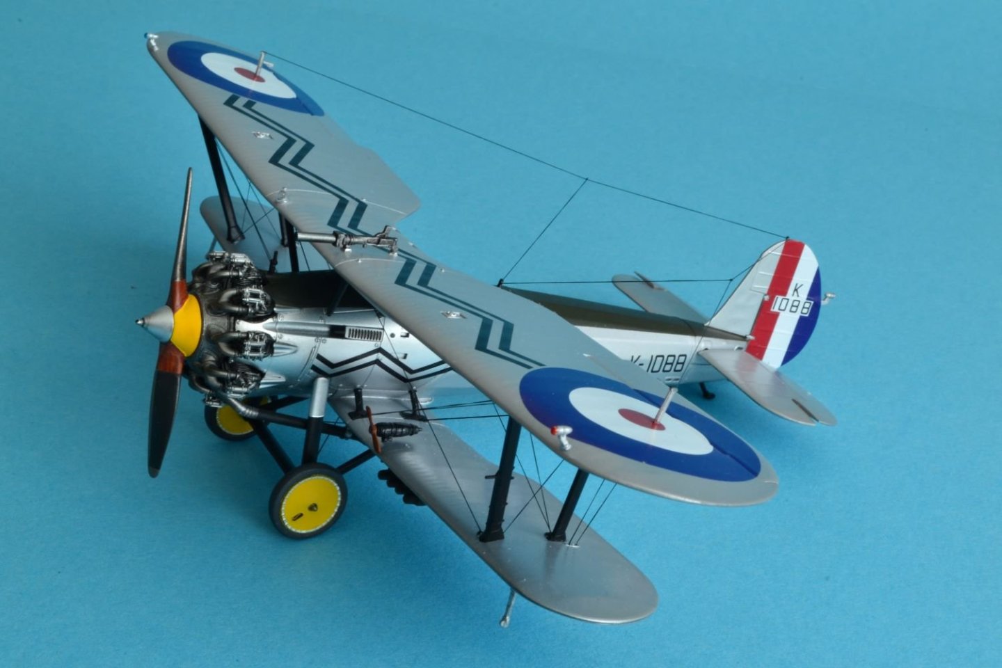
-
I have just seen the last pictures of your finished Arado. It looks great, you built an impressive model very carefully detailed and finished. You implemented a rather high degree of weathering, but that looks quite credible. Well done, especially thinking that you are new to this genre.
Best regards,
Dan
-
-
Glad that you recovered so well the number decals. As you said, the finish looks like a piano, simply beautiful.
Cheers,
Dan
- Old Collingwood, Canute, king derelict and 1 other
-
3
-
 1
1
-
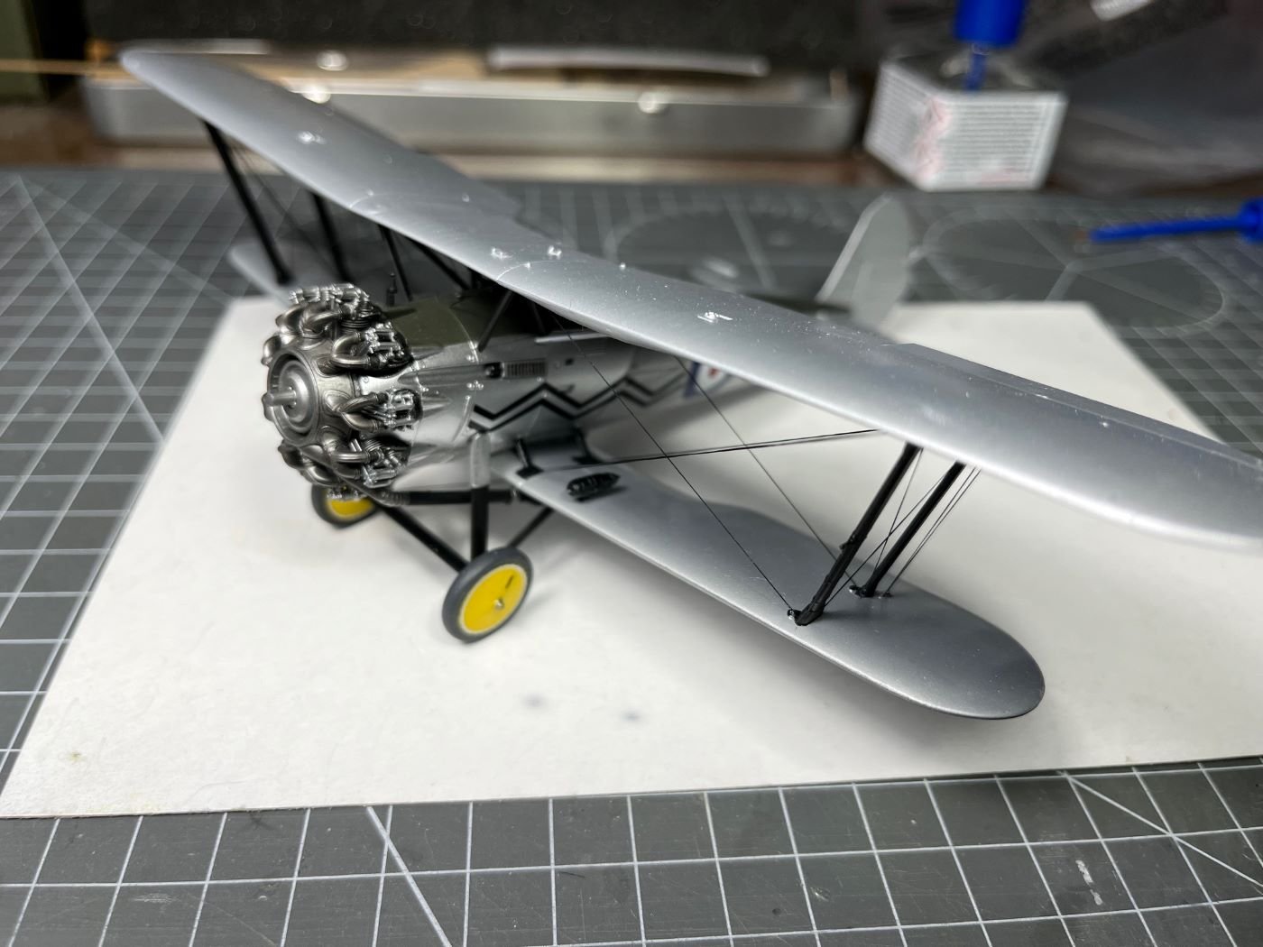
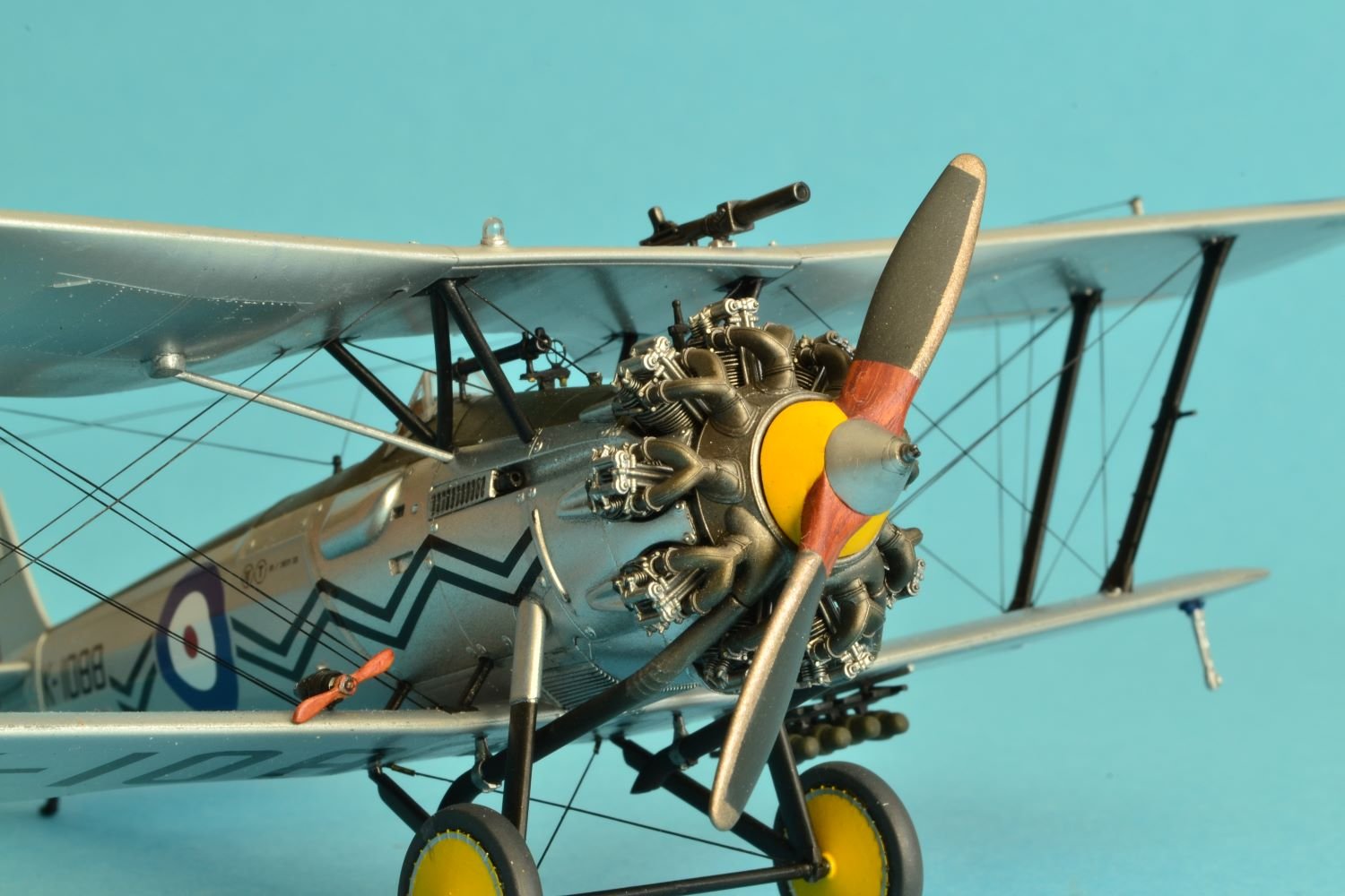
On 11/4/2025 at 11:01 PM, gsdpic said:
The whole build looks really good, but the finish on the main prop is really outstanding, with the wood, yellow paint, and three different metal colors, and just the right amount of shininess.
Thank you Gary, for your nice comment. Indeed, it was a bit of a work to paint all the various finishes, but it paid off.
Regards,
Dan
- Javlin, Jack12477, Old Collingwood and 3 others
-
6
-
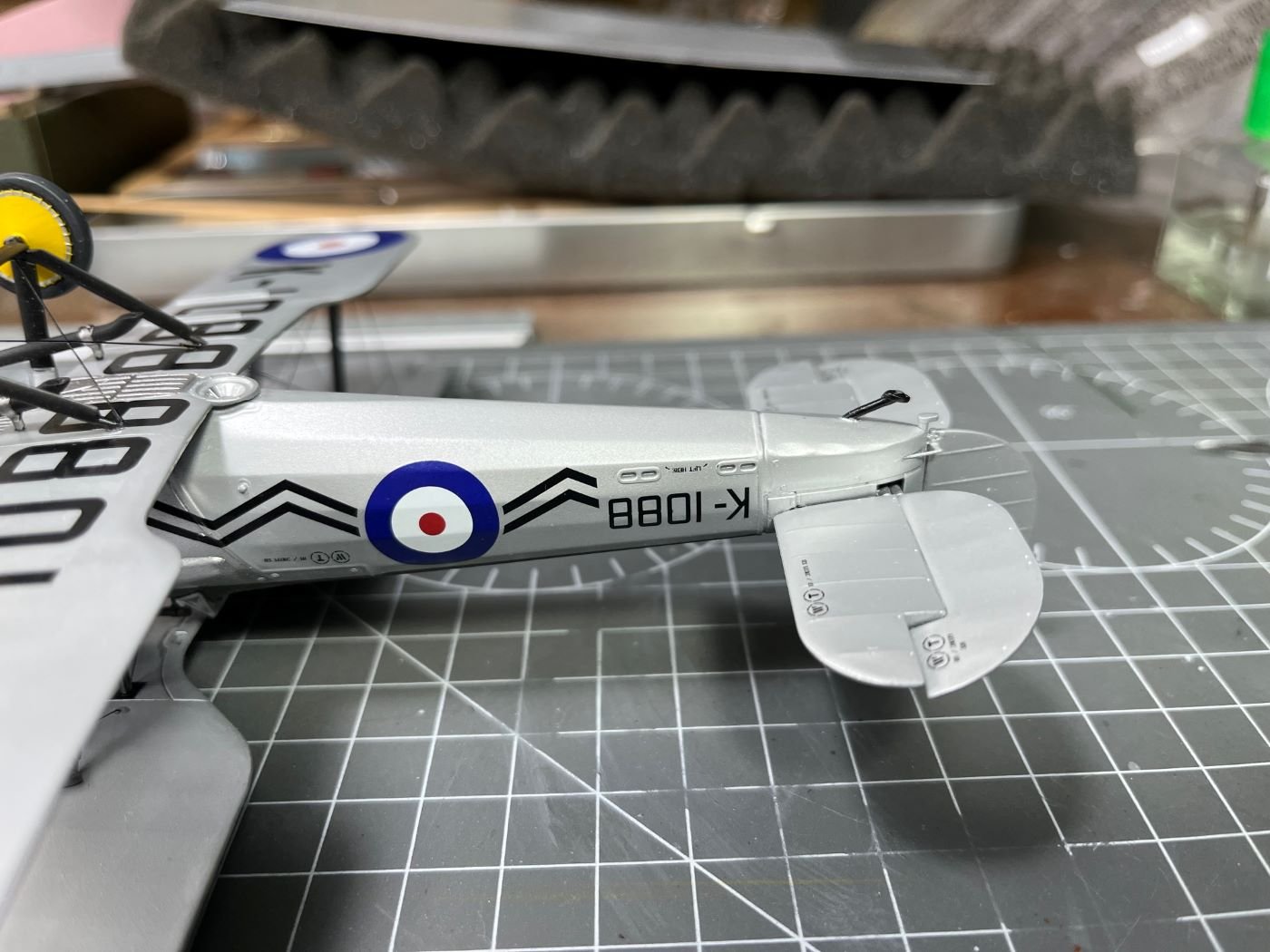
A very short post with only one picture just to show the repaired tail skid (as I said, I replaced the bent part with a piece of brass tube):
To answer to Andy, @realworkingsailor, this picture shows also one of the fin flash decals that are now glued on.
Due a trip abroad, I will have this build on hold for a while.
Enjoy your hobbies and see you in a couple of weeks,
Dan
- king derelict, AJohnson, ccoyle and 6 others
-
9
-
4 hours ago, ccoyle said:
I have a similar issue with some of my card airplanes. After they've sat on a shelf for several months, I sometimes notice that the landing gear have sagged. I don't usually have much motivation to repair them. My modeling mojo tends to regard finished models with a bit of indifference.
In fact, this is why I need to repair it asap before I finish the build.
Cheers,
Dan
-
1 hour ago, realworkingsailor said:
Nice looking airplane! I can only begin to imagine how difficult it would be to avoid marring that kind of finish!
Out of curiosity, will you be adding the fin flash decals as well?
Thanks Andy!
Indeed, it is very easy to damage the finish and the more you go on with the build, the more difficult is to repair it. It was an interesting building experience.
For the fin flash there are two options, one is a complete three colors decal for the complete rudder, the second is to leave to the modeler to paint the three bands and then just add the identification letters and numbers. At this point, I am a bit tired of this model, so I am going for the quicker former one.
Cheers,
Dan
-
Hi, thanks for the notes and the 'like's!
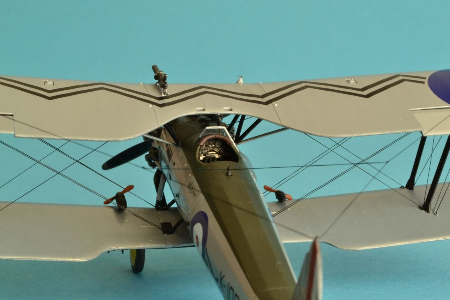
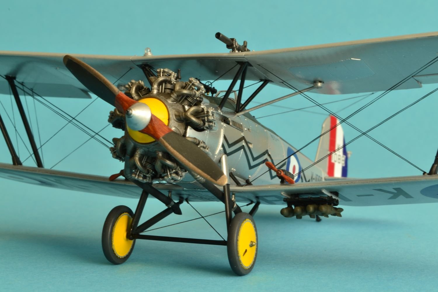
I am now completing the application of the decals that, as I said earlier, are of very good quality. Some of them are really large and some care is necessary to avoid folds and bubbles. The lower side is completed: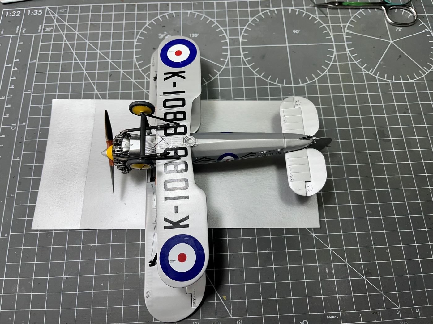
What is still missing on this side is the small rack with the bombs and the transparent cover of the ventral light. The upper side:
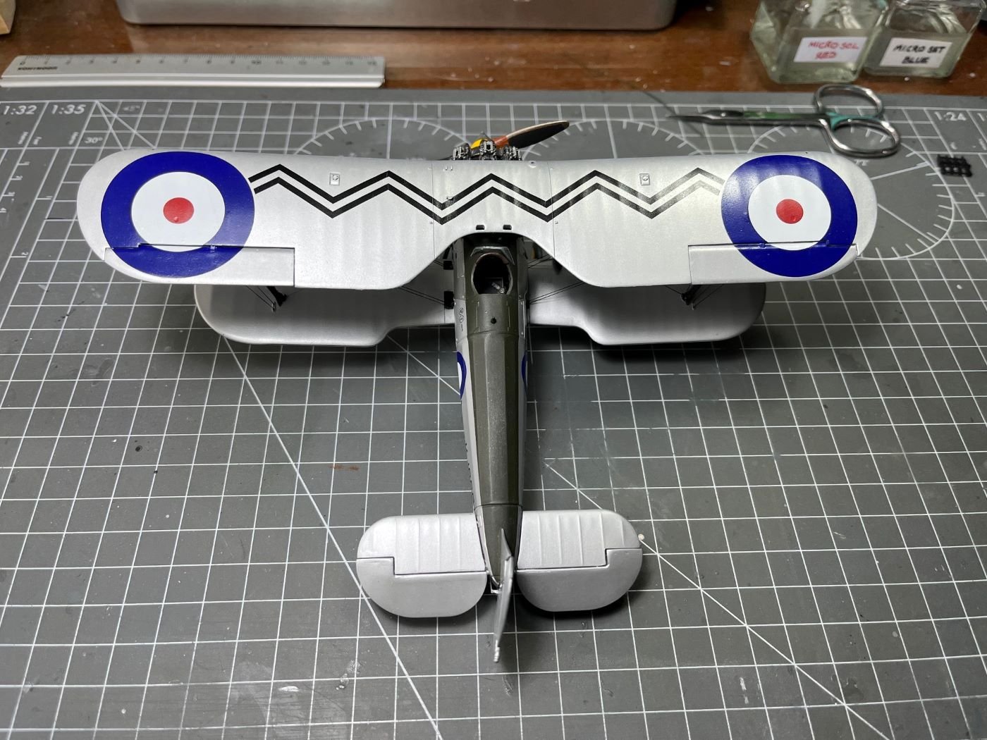
Here a number of small items needs to be completed. Once well cured, I think of sealing these decals with X-22.
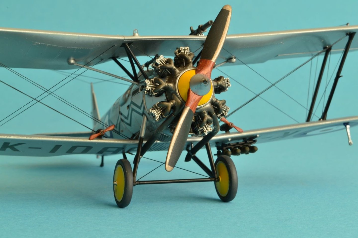
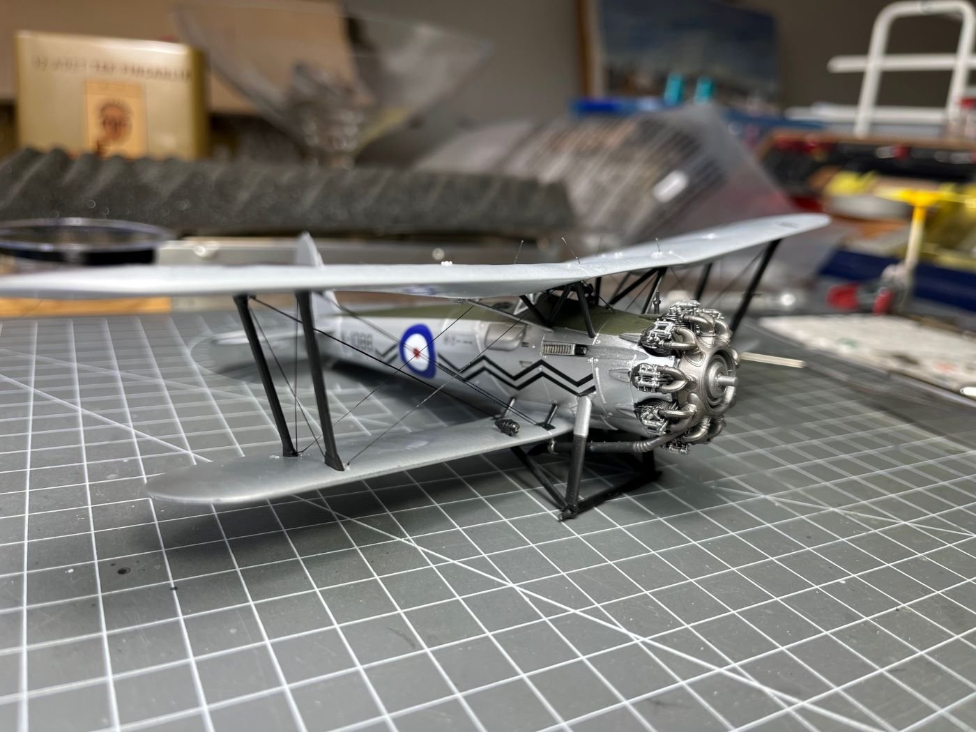
The propeller was painted following pictures found on the web along with the small propellers of the power generators: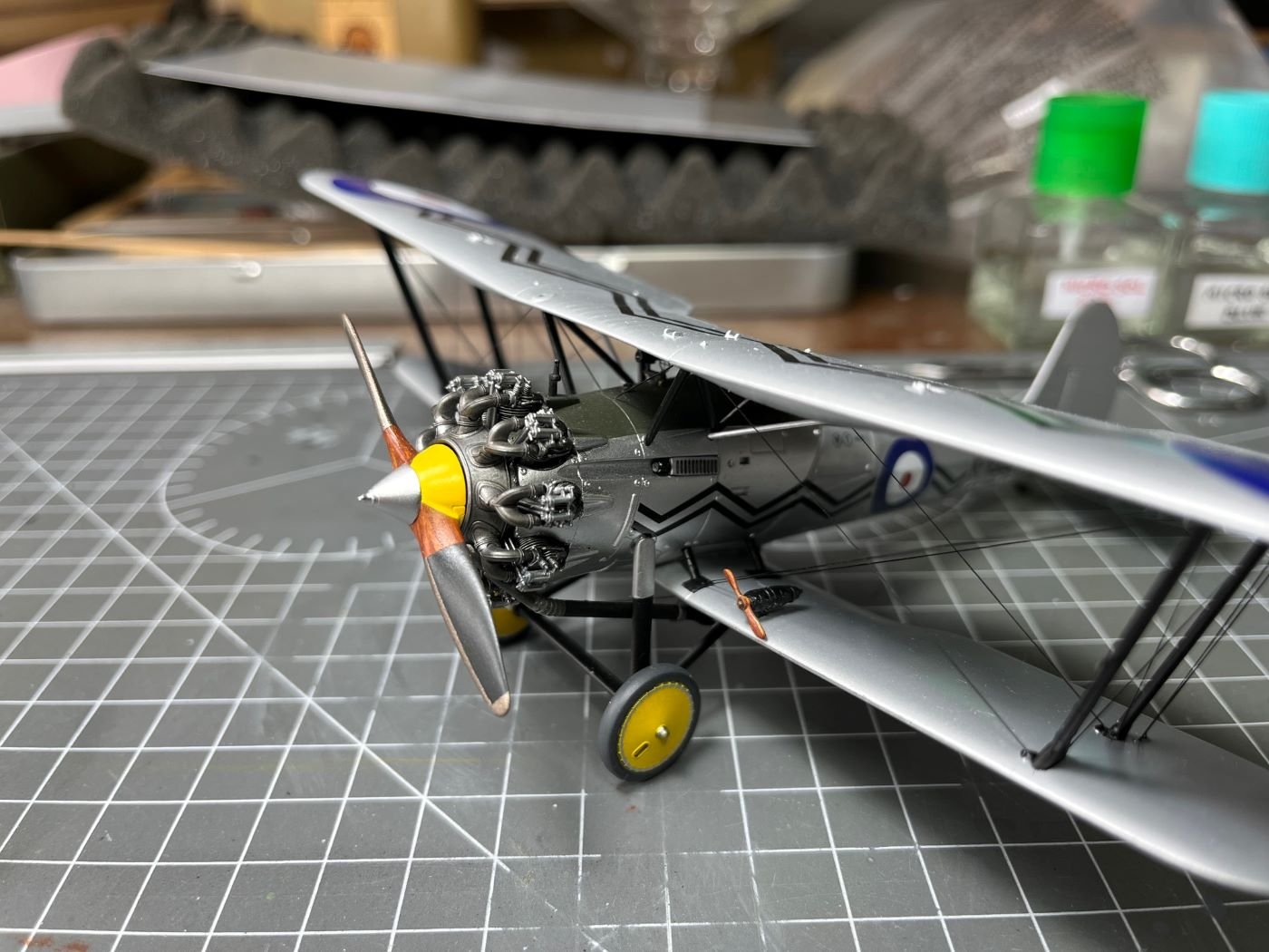
Wood grain was sketched with an oil brown color.
Unfortunately, handling the model, I found the the tail skid was bent. This might be due to the not so good plastic material that has poor mechanical qualities and get easily yielded.
A small surgery will be necessary to replace the plastic part with a brass tube. All these final bits take a lot of time for me and I have to put extra care for not messing up things at this stage.
That is all for now, probably the next post will be the final one.
Best regards,
Dan- Diver, GrandpaPhil, Landlubber Mike and 14 others
-
8
-
 9
9
-
14 hours ago, yvesvidal said:
Well, I hope they planned for a variable section, otherwise the lift forces would cancel each other. I am sure, the French engineers thought about this and they may have done some tests with models, before spending all that money for nothing.
Thanks for your answer. Surely the French engineers made extensive testing to support their design. This is the norm. As a side note, I just mention that a symmetric section is also able to produce lift when it is at an angle with the flow. A symmetric section would have been much easier to be build in a controlled way. I think that with an annular wing, the lift is not just the integration of the local forces of the sections, but also the synergy that the tube produces as a whole when at an angle of attack. It goes without saying that when the plane is vertical, it must entirely rely on the trust of the engine to stay aloft.
Best regards,
Dan
-
On 11/1/2025 at 9:42 PM, DocRob said:
Somehow I missed your great build, Dan. I really like your methodical approach and the Bulldog looks fantastic.
Thank you Rob, happy that you like it.
Cheers,
Dan
- Canute, Old Collingwood, AJohnson and 1 other
-
4
-
-
Awesome thematic collection, Yves. Perhaps, my preferred is the French Coleoptere. I am amazed by the fact that it flew and somebody could control it.
BTW, you wrote that the annular wing had a variable section along the circumference; is this documented or is a deduction of yours?
Best regards,
Dan
-
-
Very neat and awesome model!
Cheers,
Dan
- AJohnson, Old Collingwood, Dave_E and 3 others
-
6
-
22 hours ago, gsdpic said:
Just catching up on your build. The finish looks great. One of these days I'll get serious enough about modelling to wear gloves while handling the under construction build
Thanks Gary for your appreciation. Indeed, when I have to apply some pressure to hold firmly the model, a latex glove helps a lot not to leave marks on the paint, especially when dealing with metallic paints.
16 hours ago, king derelict said:Looks great Dan. Rigging still frightens me so I’m not sure when I’ll dust off the biplanes in the pile.
Thanks Alan, it is true that rigging a biplane takes some time and patience. I had to break it down in several sessions to make it more bearable. But, in the end, there is some sense of satisfaction when it is completed.
Best regards,
Dan
-
Hi,
I went on with rigging my biplane after having decided to use an elastic thread for that. This was a first for me and I went through a learning curve with the application of this stuff.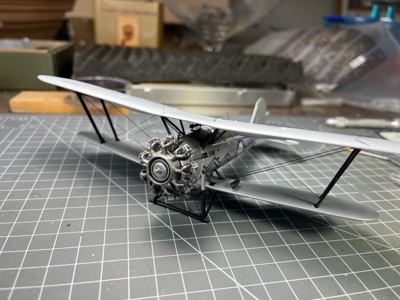
Practically, that means that the last wires are more cleanly glued that the former ones. I will have to live with that. Some of them are going through the top wing, as shown below.
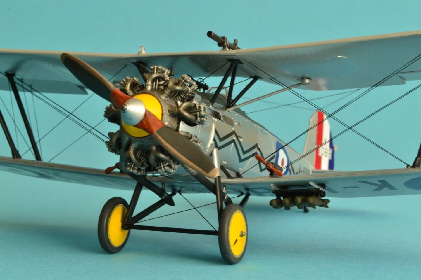
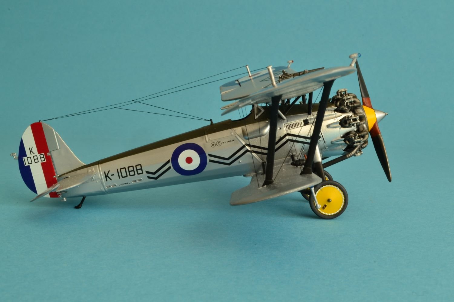
After some fights, the rigging is completed and the top wing is sanded and eventually painted:
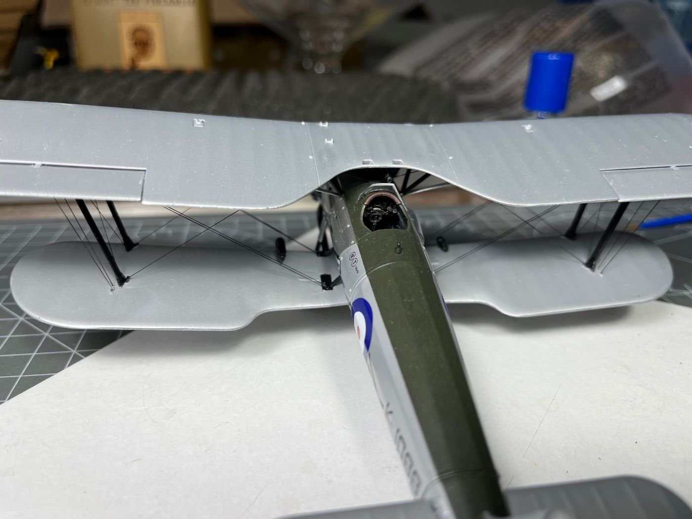
And now, this is how my Bulldog is resting on its own wheels:
As a conclusion, I can definitively say that I will have enough with biplanes for quite some time. Now the remaining work should be downhill (I know, I should never say that in advance).
Best regards,
Dan


Lady Nelson by Danstream - Amati/Victory Models - 1:64 scale
in - Kit build logs for subjects built from 1801 - 1850
Posted · Edited by Danstream
Dear all,
I previously halted my build after some perplexities about the apparent scale inconsistency of this model that was discussed in the last posts. However, many other modellers better than me completed this model with the items included in the kit, so I am going to try the same and see whether I can complete it as well.
I decided to use the cannons of the kit and after filing the molding flesh as good as I could, I sprayed their metal parts with a Mr. Surfacer gray primer.
After that, I painted carriages and barrels with Tamiya paints. This is how they look once pinned on the deck of the model:
As a side note, I can't help noticing the size mismatch between the cannons and the superstructures on the bow. As said, I will have to live with that and I will not come back on this point any more.
After a visit to the maritime museum of Amsterdam, and having taken note of few period models exposed there, I added a rail to the stern panel as seen on some of these models.
Next, I am going to add a simplified rigging of the cannon carriages.
That is all for now,
best regards,
Dan