.jpg.2c2c29e54623bd7b752bc2cdab599665.jpg)
Danstream
-
Posts
755 -
Joined
-
Last visited
Content Type
Profiles
Forums
Gallery
Events
Everything posted by Danstream
-
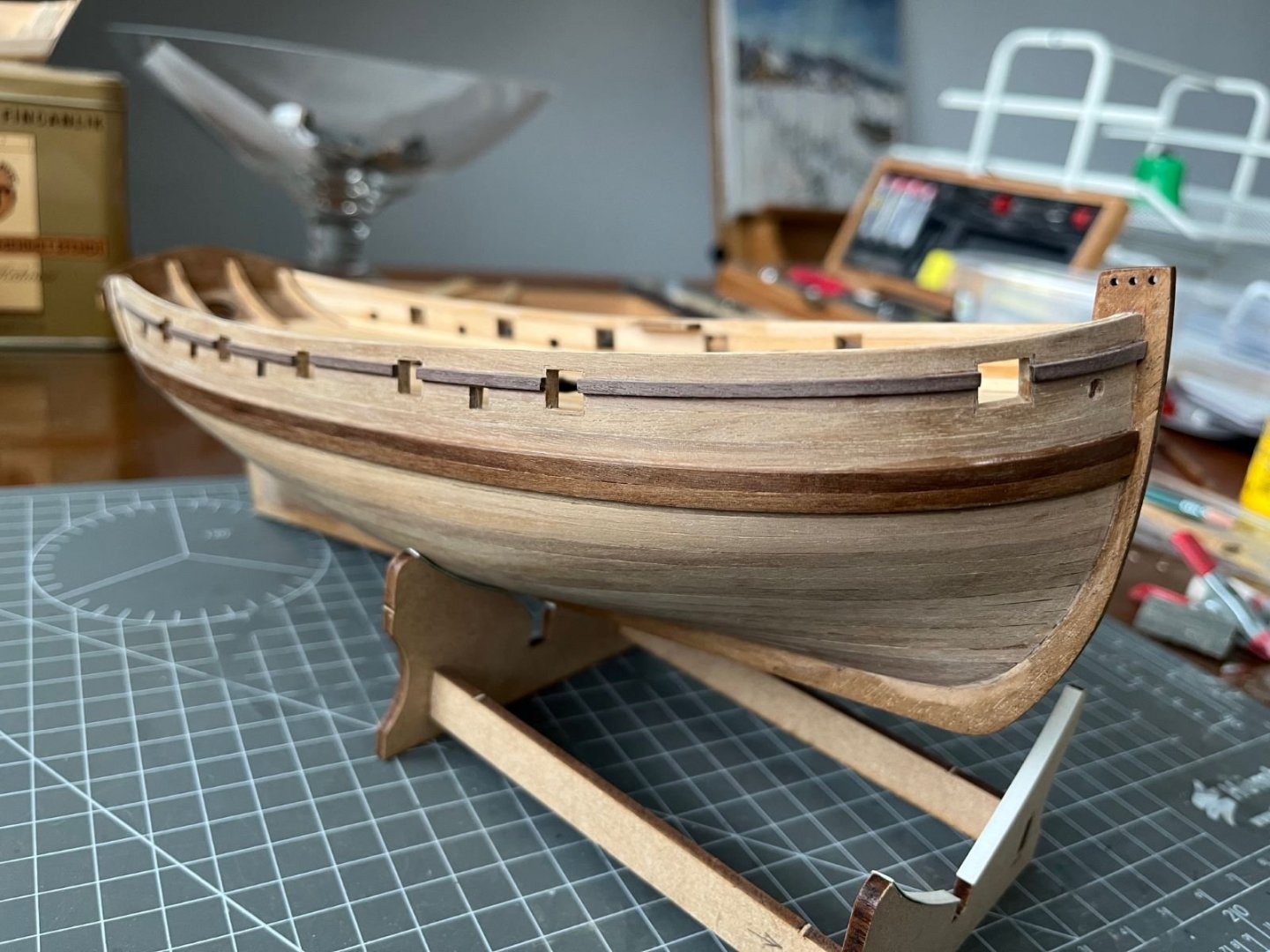
.thumb.jpg.c459ce4140b54c12eddb8eedfd446df3.jpg) Good job on the first and second planking. The second one looks beautiful. I am impressed with how much you manage edge bending the planks in the bow area. I always crack them if I exceed a reasonable entity. Surely another build of yours that I will keep following. Cheers, Dan
Good job on the first and second planking. The second one looks beautiful. I am impressed with how much you manage edge bending the planks in the bow area. I always crack them if I exceed a reasonable entity. Surely another build of yours that I will keep following. Cheers, Dan- 35 replies
-
- 4
-

-

-
- vanguard models
- Adder
- (and 2 more)
-
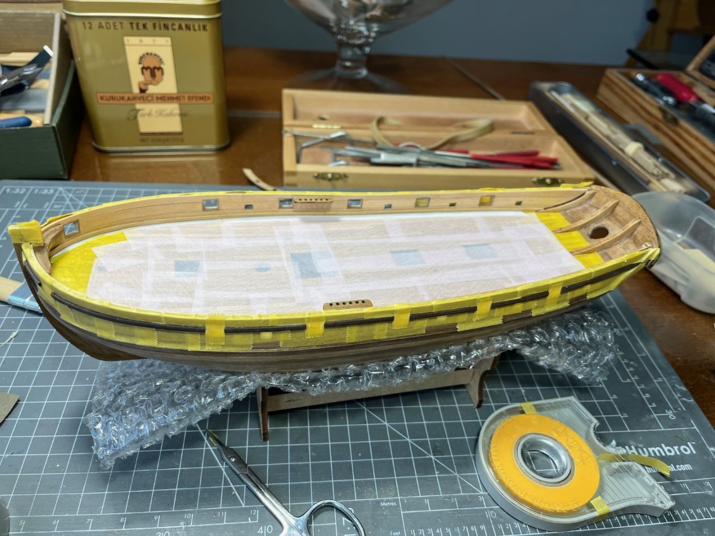
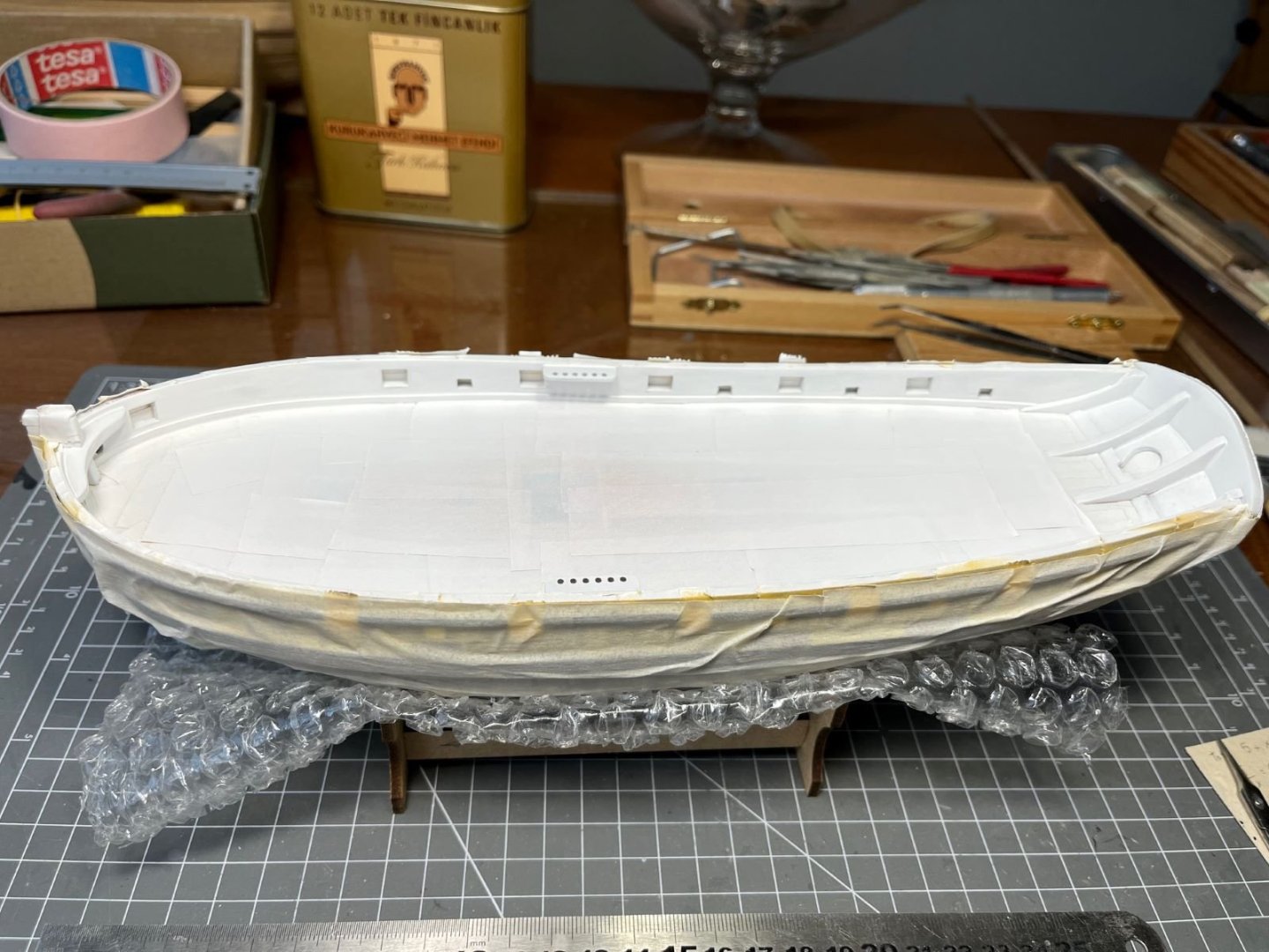
Hi all, some progress on my Lady. After the wales, I finally ended the major works on the hull on its stern area. As I wrote previously, I didn't like to see the ends of the planking strakes because their bond lines looked bad. Hence, I covered those with an additional layer of thin walnut obtaining a configuration that I think looks nicer and cleaner. The sheen is due to the varnish that I used to seal the grain of the wood and that I brushed with a fine steel wool. Next I will brush on a satin clear. Then, I masked the hull to prepare it for painting the inner sides of the bulwarks. To obtain a good uniform base for the red paint, I sprayed a coat of Tamiya white primer, which also revealed few blemishes that had to be filled and smoothed. Finally, I airbrushed the red paint which I obtained with a mix of 80% of Tamiya flat red and 20% of Tamiya flat red brown to make it darker than pure red. To finish the waterway, I added a small wooden strip at the base of the bulwarks. The paints that I used were from the Tamiya acrylic line which spray very well, but they are very matt, almost chalky when dried and their finish is very delicate getting very easily spoiled just by touch. Hence, I brushed on a coat of Humbrol satin clear which made the surface less matt and more resilient. That's all for now, next I will paint the exterior of the hull and install the cap rails. Best regards, Dan
- 87 replies
-
- 8
-
-
- Lady Nelson
- Amati
- (and 1 more)
-
Great model, I hope it happened nothing that you cannot recover. May I ask you how did you brought out the frieze details from the black background? Thank you and best regards, Dan
- 8 replies
-
- 1
-
-
- Lady Nelson
- Amati
- (and 1 more)
-
I didn't comment much, but I am following your build. Dutch vessels are not seen often around, but as other have said, they have played an important role in history. In addition, they have set the standards for others. I have one of these in my wish list. Congratulations for your build so far, it is evident that your modeling skills are improving. Kind regards, Dan
-
This is a very nice and credible result. This impressive aeroplane with a metallic finish looks great. The metallic finish with the grey patches, its muted reflection and subtle discolorations looks authentic and very 'aeronautical'. Kind regards, Dan
-
Indeed, this is the natural conclusion. I will redo it as well, so I am not bothering more than necessary. I suggest you inspect the pictures of period models of British cutters published in this forum (if you have not seen them yet) to get inspiration about plausible configurations for the new pieces: In addition, I visited the build log of a Lady Nelson model built by @glbarlow, who discussed the problem and re-built the parts in subject (but probably this issue had been treated also by other modelers). You could have a look also on that. Cheers, Dan
- 39 replies
-
- 2
-
-
- Amati
- Victory Models
- (and 1 more)
-
Thanks for the head up Roger! Now it is clear that I need to take out the bowsprit and its support bracket and make some tests. Cheers, Dan
- 87 replies
-
- 2
-
-
- Lady Nelson
- Amati
- (and 1 more)
-
Hi Roger, thanks for your comments. It took a while to me to understand the position of that part and to decide the position of the catheads. The drawings and the pictures are neither clear nor unambiguous. Eventually, I decided that the catheads will be positioned right past (astern) the first openings. I also slightly reshaped that 'V' part making it a bit slimmer. As far as your quote is concerned, I positioned that part in subject just below the the indent for the bowsprit, but I didn't do any fit check with it and with the other supporting superstructures that I haven't yet removed from the package hoping that it will be ok (I know this isn't the correct approach...). I think that I will glue in place the cap rails after having painted the inner sides of the bulwarks. Looking forward to seeing your progress, Dan
- 87 replies
-
- 2
-
-
- Lady Nelson
- Amati
- (and 1 more)
-
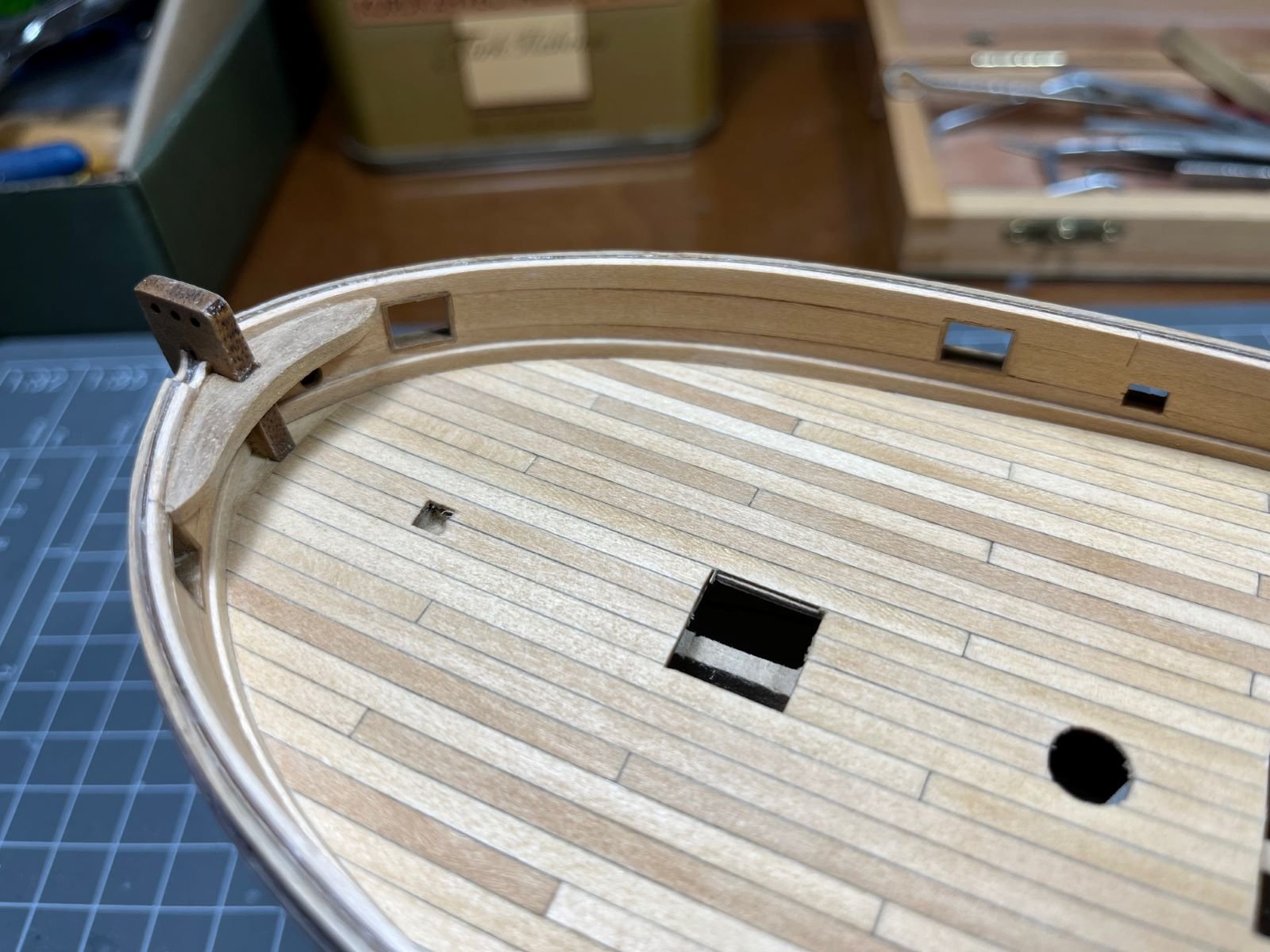
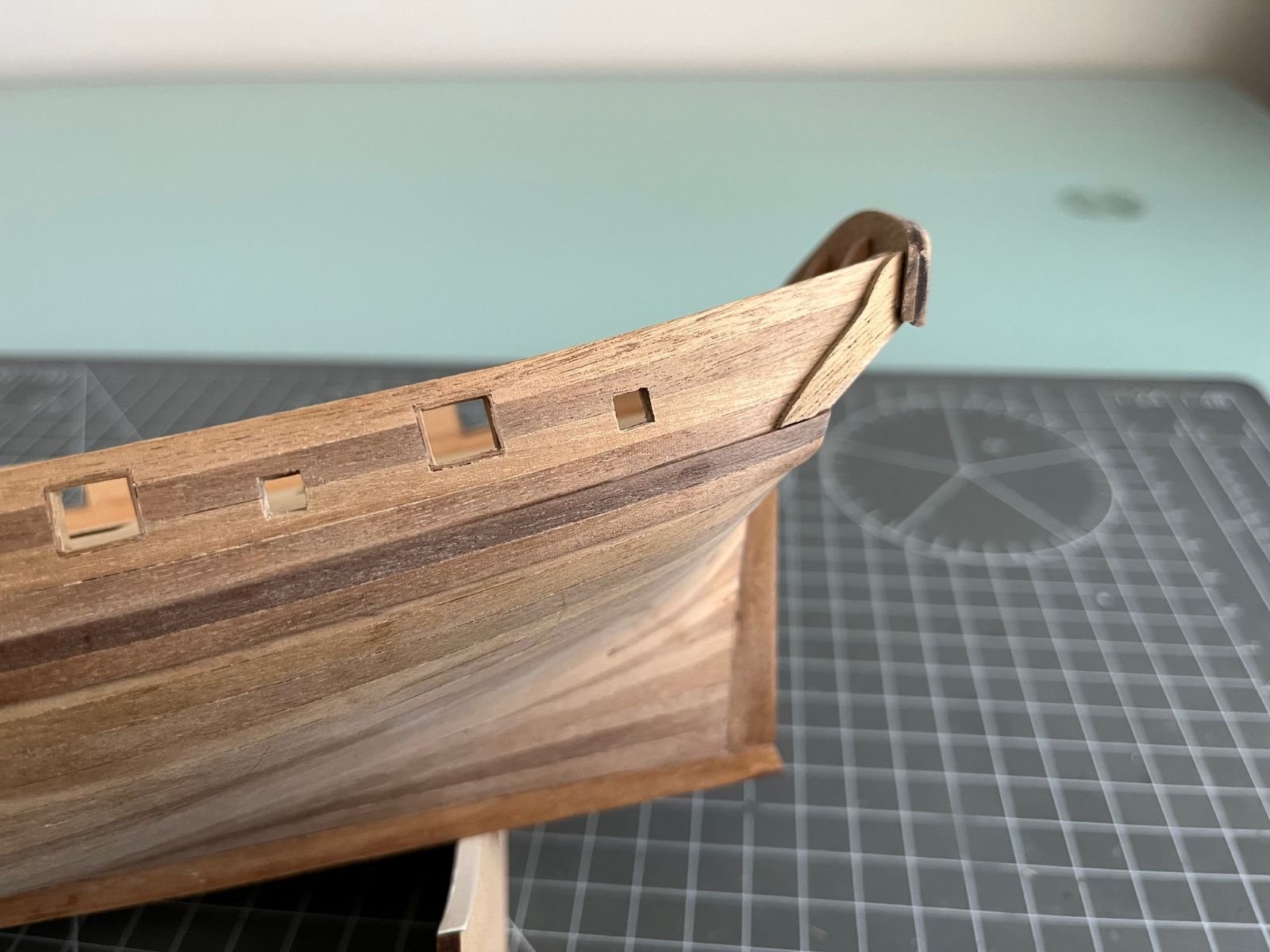
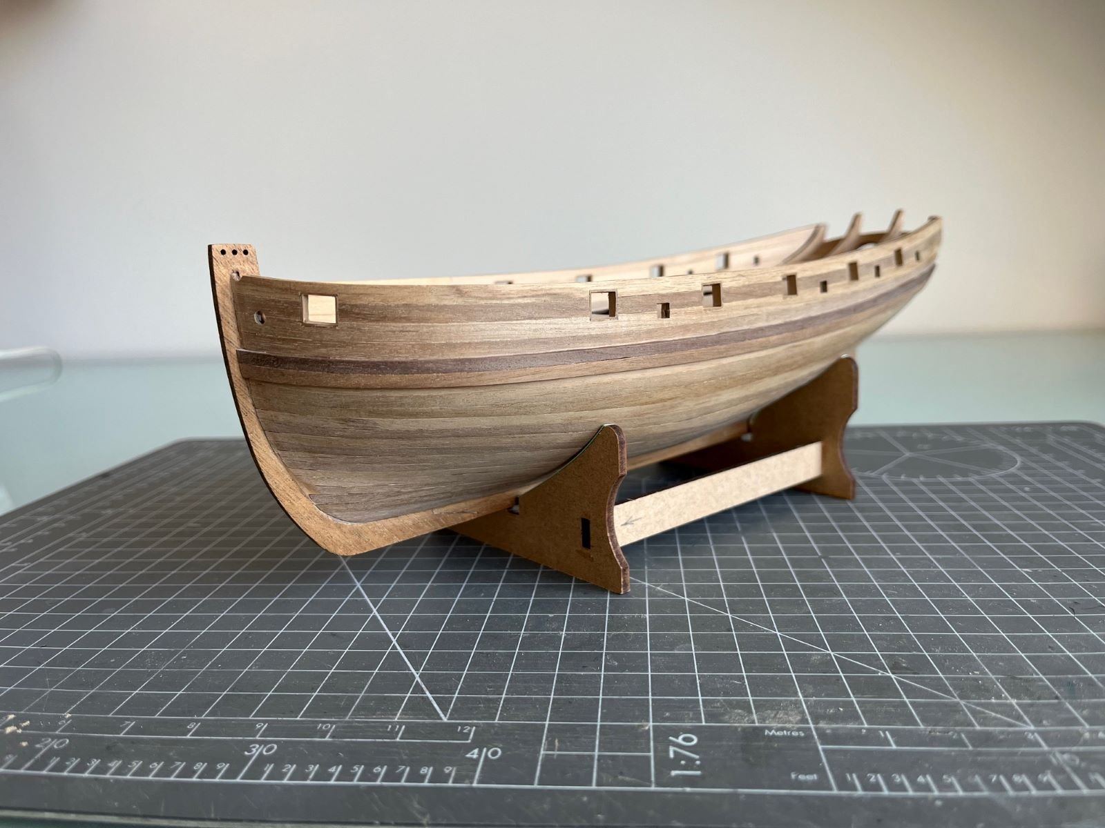
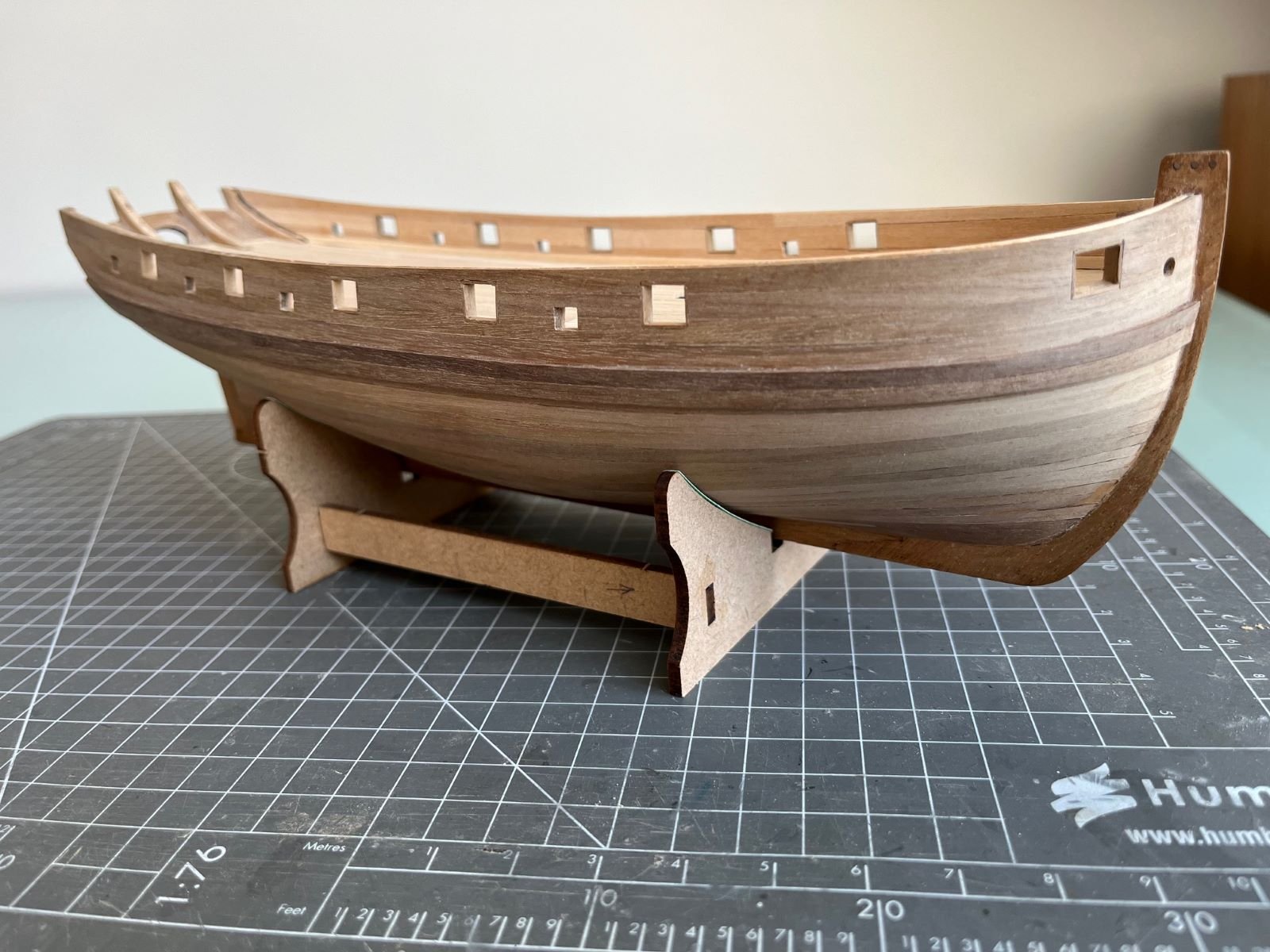
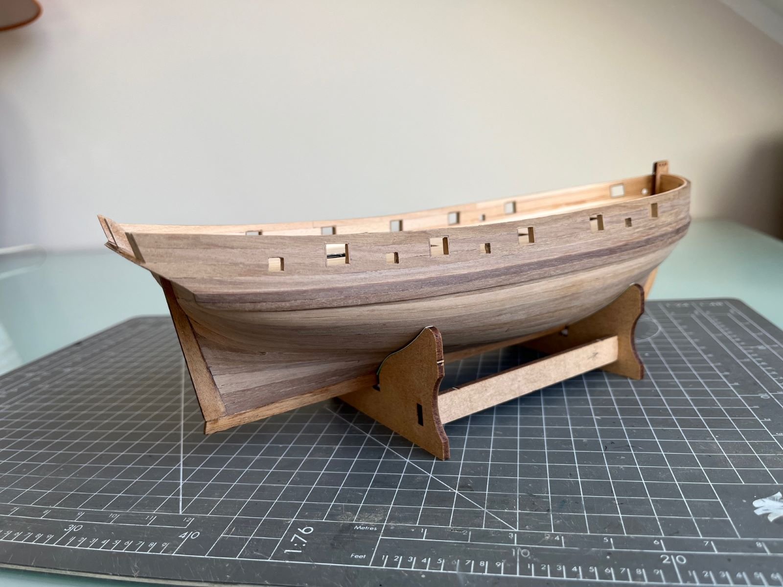
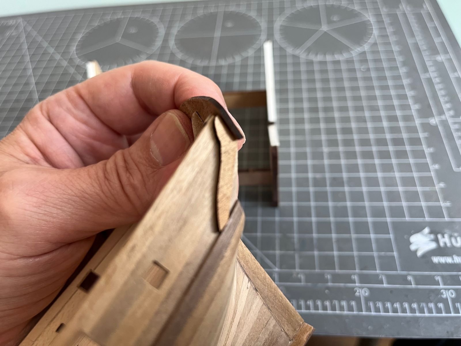
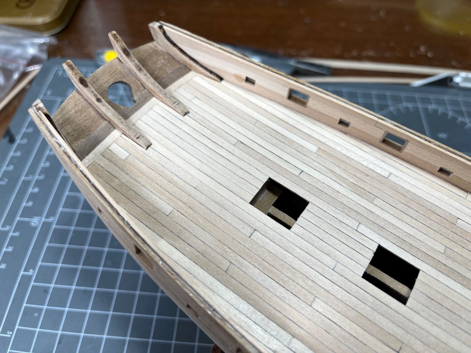
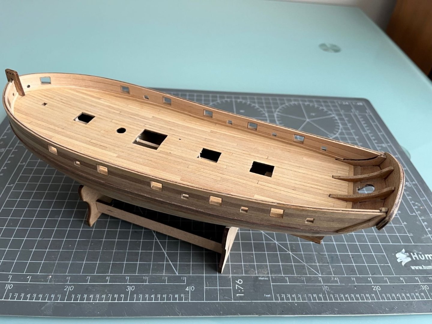
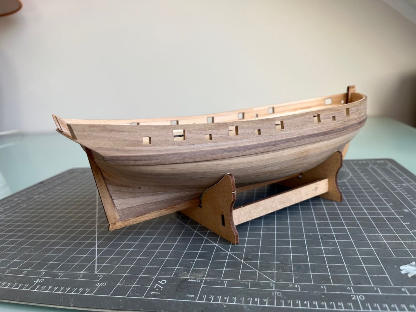
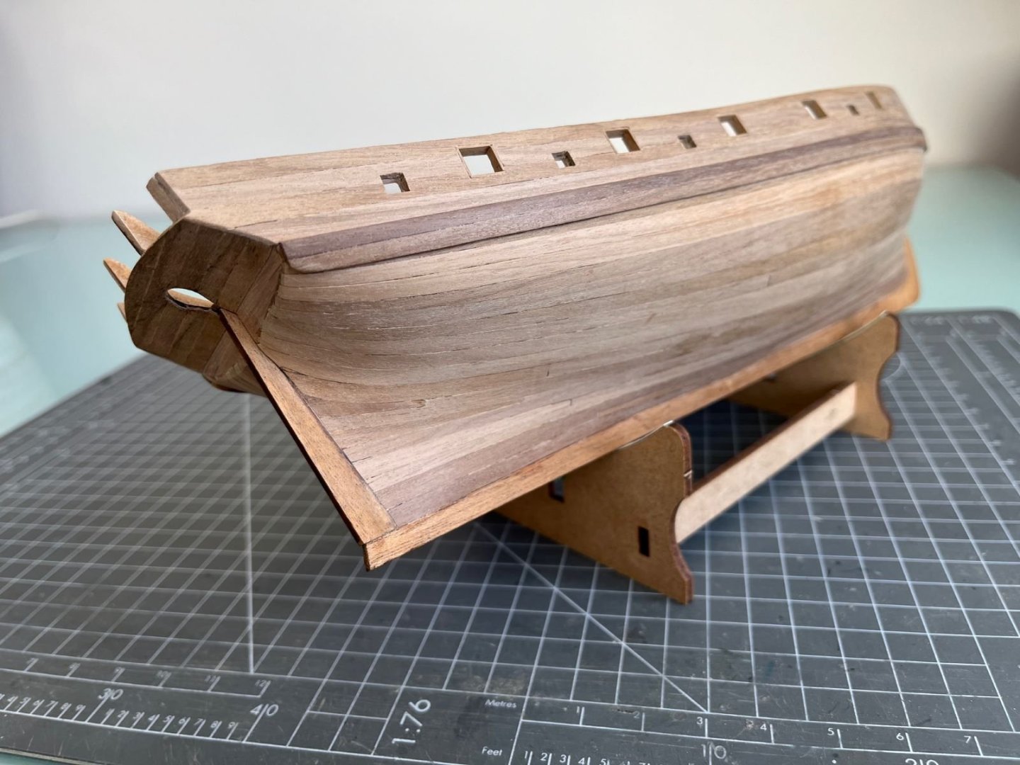
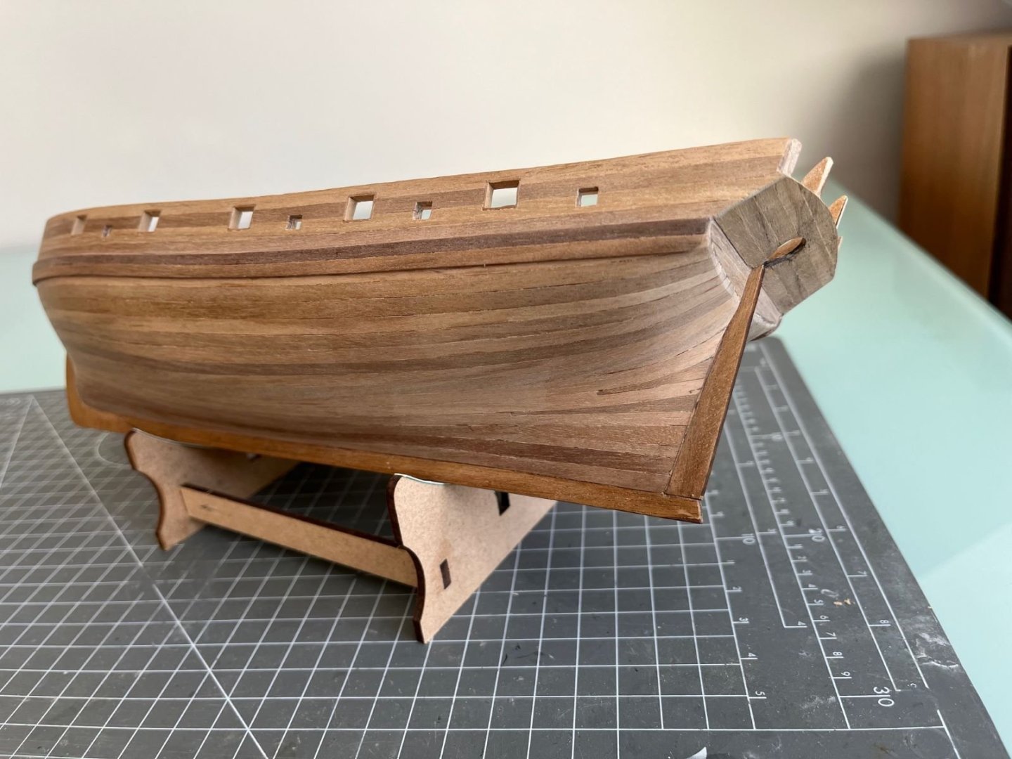
Hi all, I went on with attaching the 'small' wales to complete the hull. The function of these 'wales' is not clear to me being them interrupted in many locations by the opening for the guns. I guess they functioned as load spreader for the concentrated loads transmitted by the gun carriages attachment points. I started to prepare the inner sides of the bulwarks for painting and I started to set up the pin racks. I assume that there will be quite some tension applied to them by the rigging, hence, I pinned them to the bulwarks with brass pins. I also brushed the timbers of the deck with a transparent varnish which gave fuller colors to them. Finally, I installed the 'V' reinforcement on the tip of the bow after having discarded the part supplied by the kit because it didn't fit and having rebuilt it. That's all for now, best regards, Dan


- 87 replies
-
- 7
-
-
- Lady Nelson
- Amati
- (and 1 more)
-
Wing fillet went on like a glove!
-
That's the look of bleached deck! Very well done. Dan
- 39 replies
-
- 2
-
-
-
- Amati
- Victory Models
- (and 1 more)
-
Thanks Roger! Please, go on and be my guest, but be aware that it is a deadly boring job 🙂. (I gave up with framing the small apertures).
- 87 replies
-
- 1
-
-
- Lady Nelson
- Amati
- (and 1 more)
-
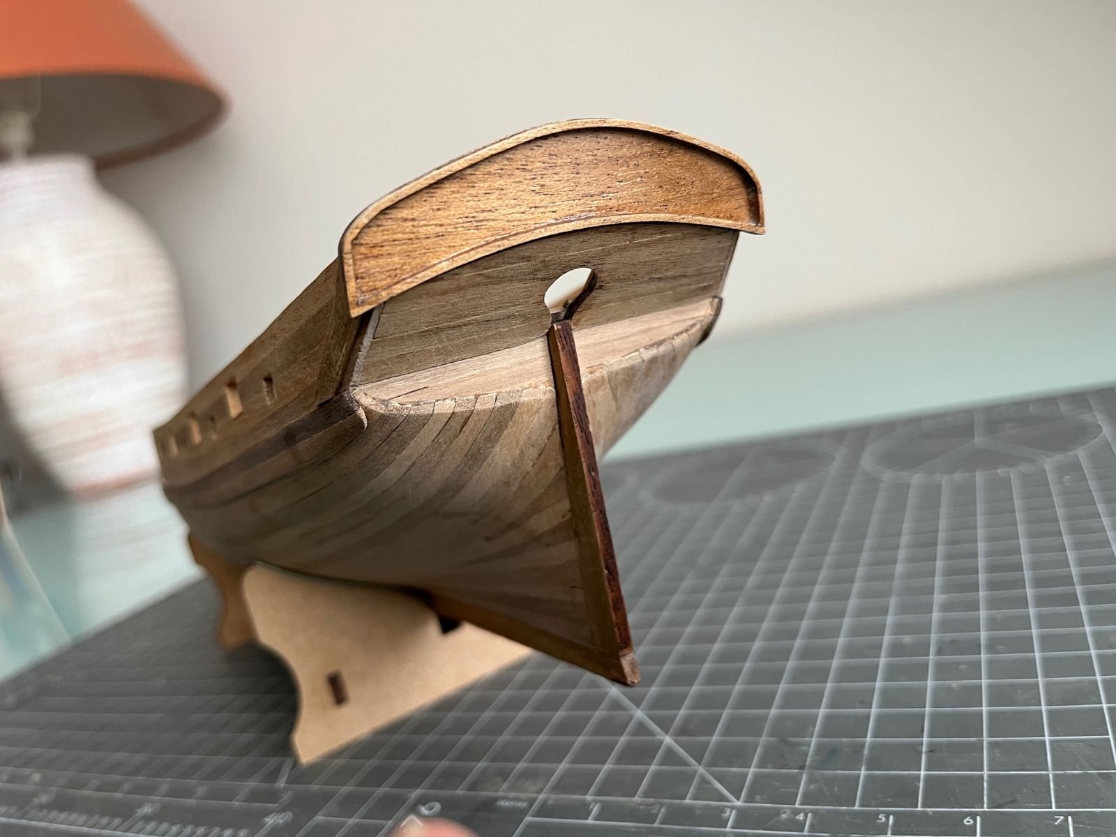
Hi all, just a very small update of my build. I prepared and framed the stern fascia and after some bending and tweaking, this part was eventually glued to its place. The result is not bad: The grain of the wood is very obvious and it needs to be addressed before painting it. The quality of the wood used for these type of pieces is quite poor, in my view. On the stern sides, I rebuilt anew the lateral fascia supports trying to match the involved angles and maintain the possibility of decorating them with the kit provided photoetched friezes. Finally, I went back to staining the deck with the aim of reducing the contrast between lighter and darker planks. After three light passes, I think I achieved a reasonable result. Just as a side note, because I didn't have any proper staining powder at hand, I ended up using my strong Italian espresso coffee as a staining agent that left a good coffee aroma to my model. Best regards, Dan


- 87 replies
-
- 7
-
-
- Lady Nelson
- Amati
- (and 1 more)
-
Great Mustang! I like also your photography. It was also enjoyable for me to follow your build. Good luck for your next activity. Best regards, Dan
-
It looks so nice! In my opinion, I would avoid a total dead matt finish (I have seen that sort of finish on wrecked planes only) and keep a bit of shine in the finish. But that's my opinion and this is your model. Best regards, Dan
-
Good result Alan! I use the Vallejo Metallic on top of Tamiya gloss black and they work fine (I find the Tamiya X-1 better than the Vallejo's). As you noted, the preparation of the surfaces is as important as the finish itself. Note that these paints can be happily mixed with each other and you can obtain subtler tonal variations if needed. Following your build, though I am a bit silent in these days. Best regards, Dan
-
That adverb 'soon' sounds a bit optimistic, but thanks for your encouragement. My next objectives are to finish the transom, glue the small wales and the cap rails.
- 87 replies
-
- 1
-
-
- Lady Nelson
- Amati
- (and 1 more)
-
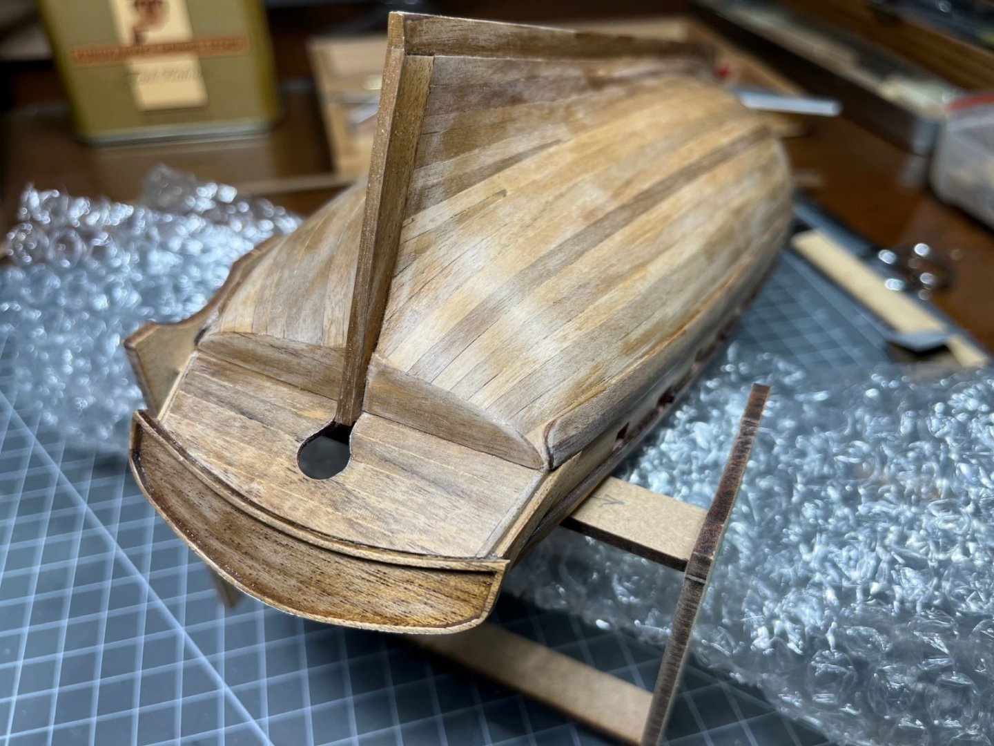
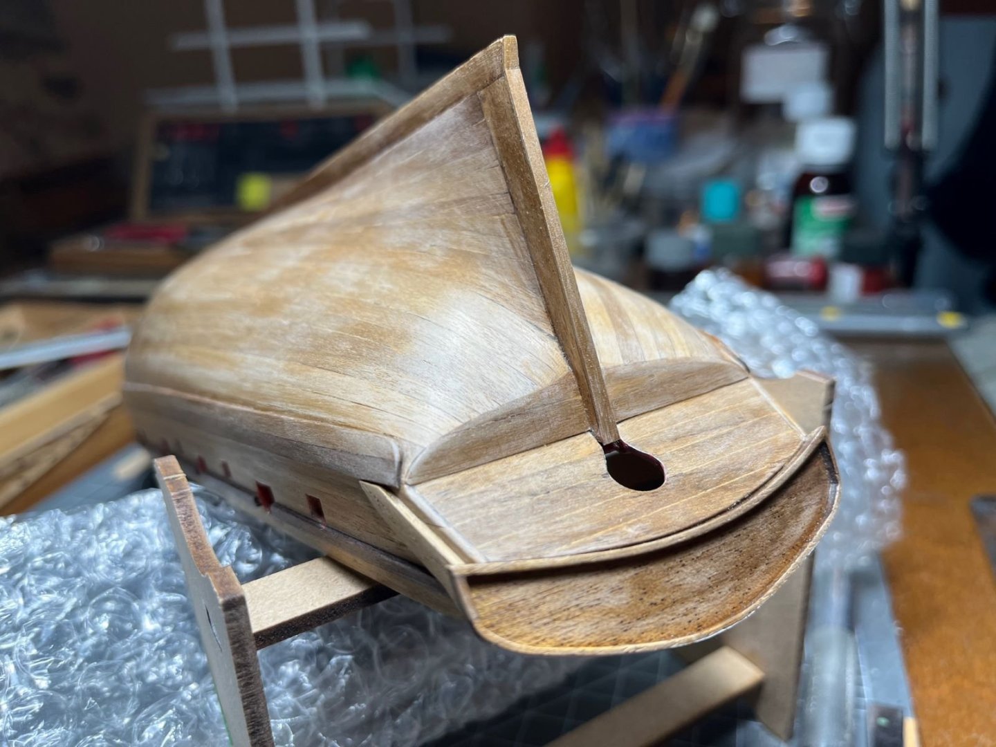
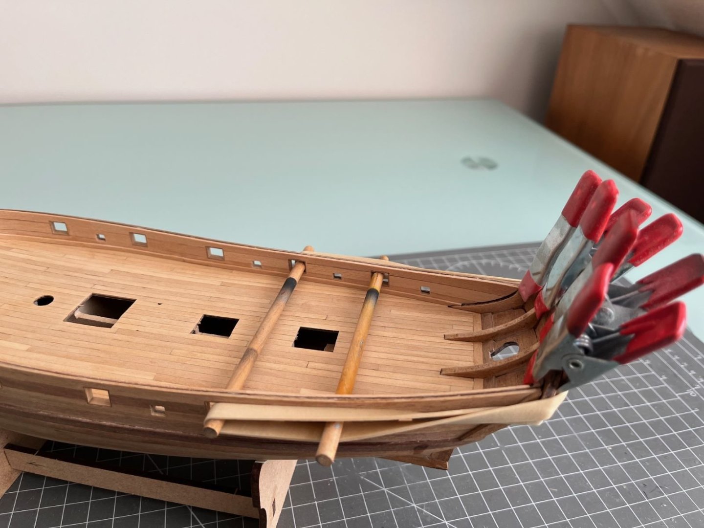
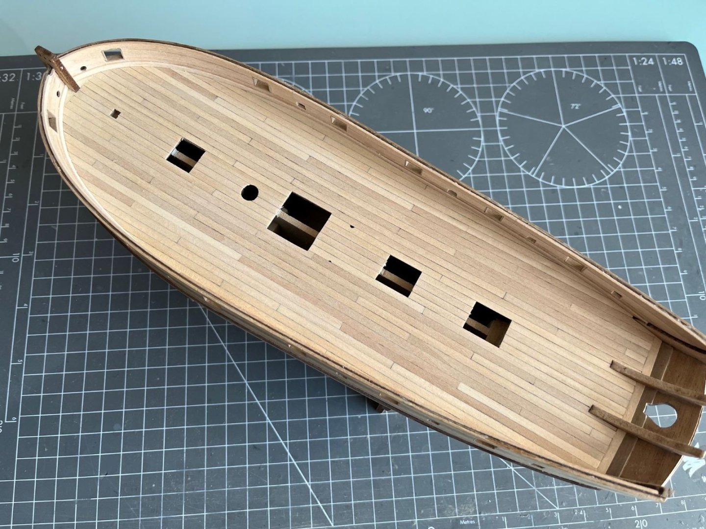
Hi all, I finished the deck with surrounding strips that should finish off the edges of the deck and resemble a sketchy waterway. I also lightly stained the timbers, but the look of the deck didn't change much. Next, I glued on the main wales as required by the instructions (3x1 mm walnut strips, 2 strips each side). At the stern, this is how I terminated the wales: I am pleased with the way the wales turned out, but I don't like the way the ends of the planks look at the stern. I am considering to cover them with a layer of thin walnut strips to hide the ends and the thickness of their glue line. Another problem, also flagged by other builds and lately also by @flyenrw in his build, is the definition and the placement of the transom band and its side support pieces. I will see how to fit them to their intended locations. That's all for now, best regards, Dan


- 87 replies
-
- 11
-
-
- Lady Nelson
- Amati
- (and 1 more)
-
The details and the finish are very good! I always liked the brutish and pugnacious look of the Tempest. I have also a metallic Tempest to be built in my stash. Just one comment, are we sure we are talking about natural metal finish and not a 'high speed silver' dope? I am mentioning that because this was the common finish of British planes after WWII when they were not camouflaged. Whatever the real finish was, yours looks great! Best regards, Dan
- 51 replies
-
- 10
-
-
-
Sorry, rereading your post, I understood now that the fit is too tight. But then, why not to enlarge the socket? (I am assuming the parts mates with a peg-socket joint). cheers, Dan
-
Maybe inserting a brass pin into the joint? Drilling into the leg isn't too difficult, you start with a very fine bit and then progressively large ones. Drilling a socket into the wing is more critical, but it does need to be dead right, a slightly larger socket will allow for some angular adjustments. If you use CA gel, the gel will fill the larger space. Of course, you have to evaluate which thickness of the wing you have there, because the risk is to go through the wing upper surface. You have to keep the leg pieces correctly aligned in place until the gel cures. Please gauge your abilities before committing the parts, I have done similar things with reasonable results. Good luck, Dan
-
🙂 You are right, I will anyway not stain the deck and let it alone for a while. I am busy now with the wales which I am going to glue with CA because I don't want to use pins to keep them in place. Thanks also for the infos about the products for weathering. Best regards, Dan
- 87 replies
-
- 1
-
-
- Lady Nelson
- Amati
- (and 1 more)
-
Very, very nice model. Livery and paint discoloration look great! Incredible 1/72 model. 👍 Congrats, Dan
-
Thanks Andrew, that's surely an effect to be considered. I am thinking of spraying the deck with a very diluted acrylic grey, say a matt neutral grey, to be sprayed after I sealed the grain as a sort of transparent filter. Do you have any experience on something similar? Thanks Ronald! I appreciate your positive approach. I will see how it looks after the varnish. See also my question in my comment above. Best regards, Dan
- 87 replies
-
- 2
-
-
- Lady Nelson
- Amati
- (and 1 more)
-
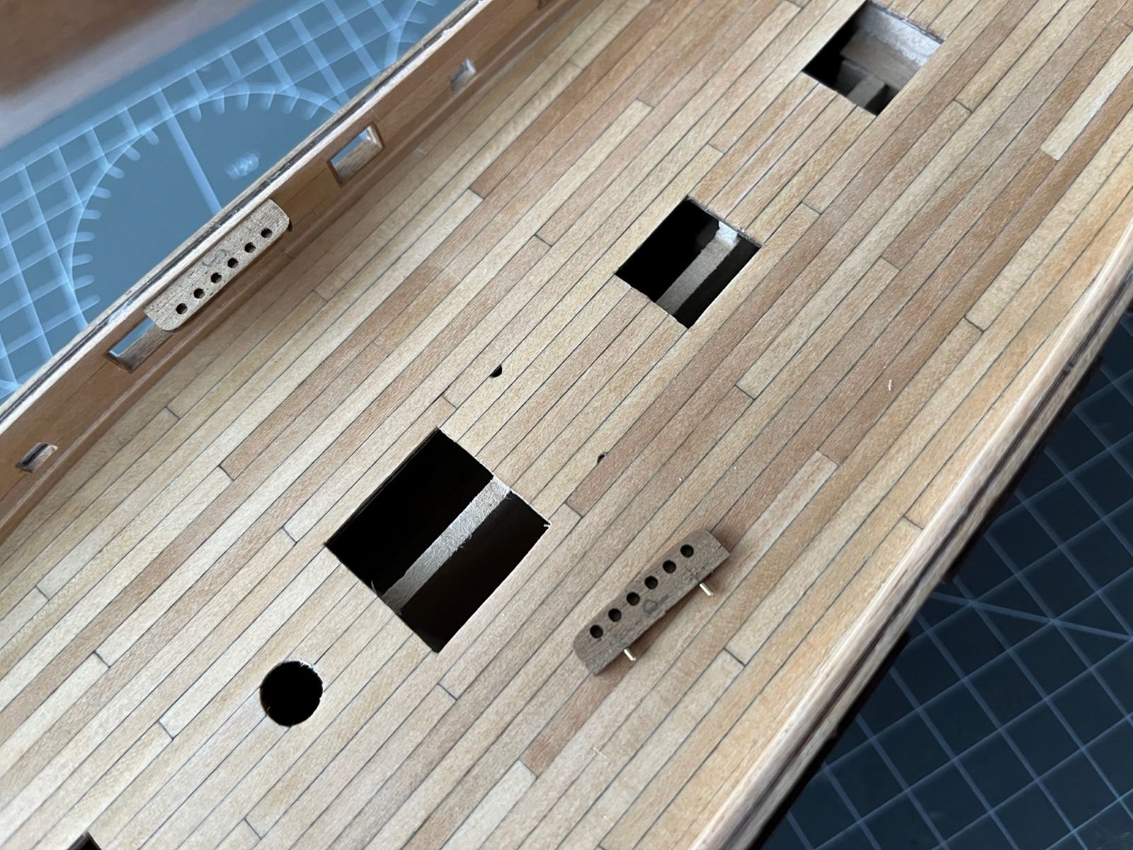
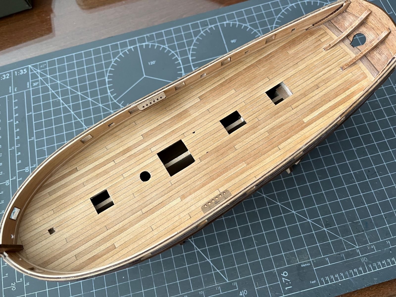
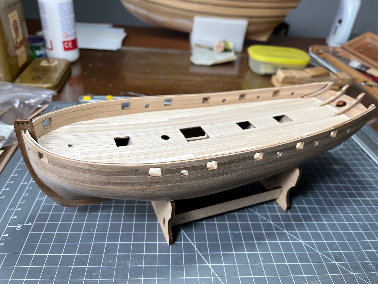
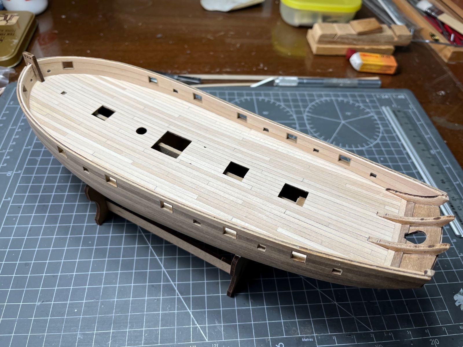
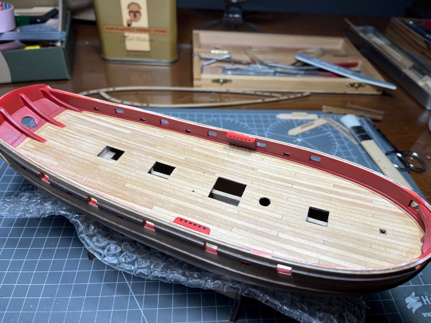
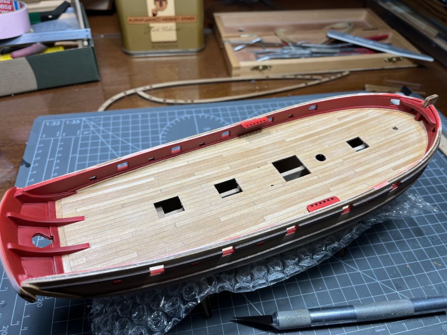
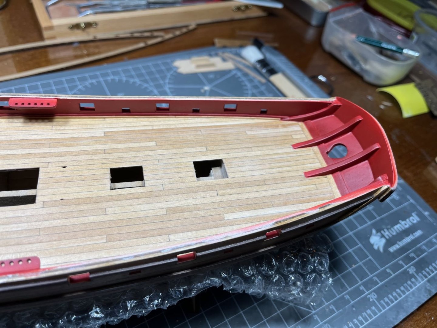
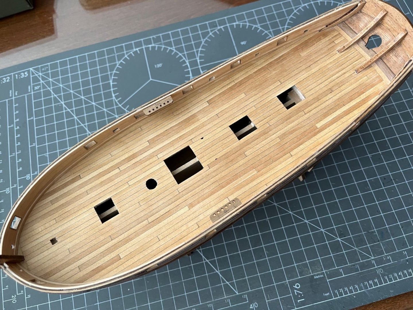
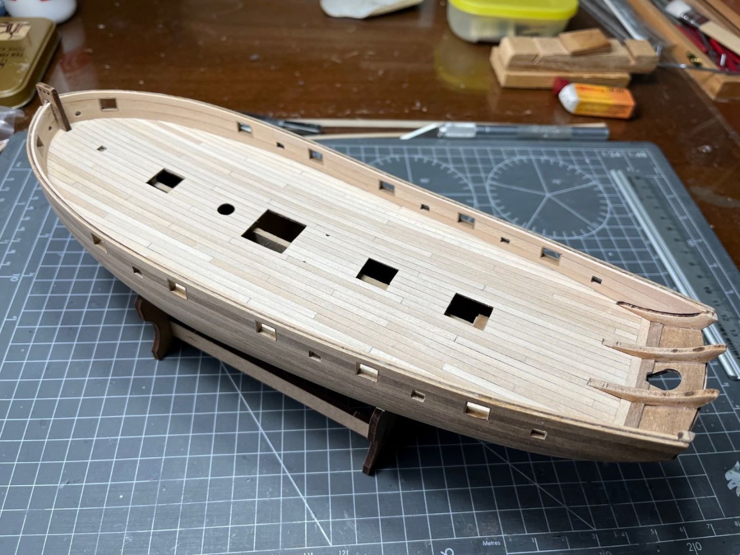
I just finished planking the deck. To be more practical, I took some short cuts and simplified the application along the bulwarks. I will refine them later. I didn't think of sorting the strips by their color, when I realized that they had different colors and the deck looked as a patchwork it was too late to do anything, hence I went on like that. I also sanded the deck with a fine grit. Next, I will seal the wood with a transparent varnish. Best regards, Dan


- 87 replies
-
- 8
-
-

-
- Lady Nelson
- Amati
- (and 1 more)