

Mike_H
-
Posts
225 -
Joined
-
Last visited
Content Type
Profiles
Forums
Gallery
Events
Posts posted by Mike_H
-
-
4 hours ago, jwvolz said:
Good start Mike.
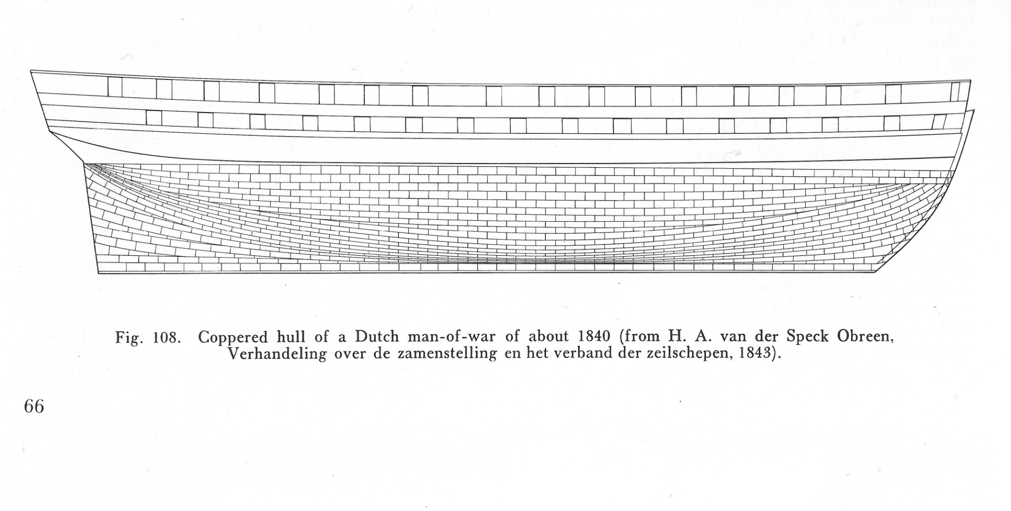
When I did Cruizer (same hull) I did one belt and then a one row belt at the waterline. It worked out well with no issues, looks good and would certainly be easier. That drawing is a two-decker so deeper hull, which would likely have a different run than a brig.
There are some pictures in my build log.
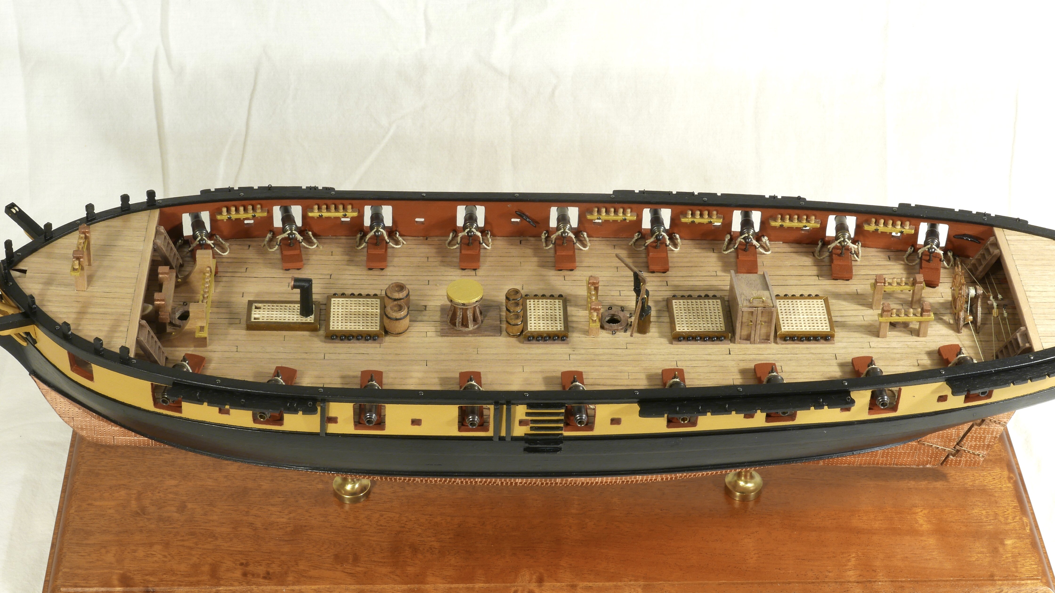
Well Joe, here's the thing. The two decker (image) has copper 30 mm in depth and 230 in length - a ratio of 1 : 7.67. My Snake (model) has copper 60 mm in depth (amidships) and 460 mm in length (exactly twice of the 2- decker image) so also a ratio of 1 : 7.67! It could be that the relatively speaking they differ in their beam - and certainly the Cruizers don't have the most elegant of lines, but then nor did two deckers.
I've given your coppering quite a lot of attention - mainly on the subject of patina and natural (or should I say nature-enhanced) ageing. Yours seems to run quite happily in horizontal rows, where as mine was very keen to wrap around the hull vertically - perhaps because I kept quite an abrupt transition from planking to keel. Anyway I took the day off work while but Admiral and Rear Admiral were head-down WFH (the Vice Admiral is hundreds of miles away very close to Snakes birthplace) . Gave me ample opportunity to push on with copper, and I'm quite pleased with how it looks (that's acquired British understatement, I'm thrilled).
Onwards!
-
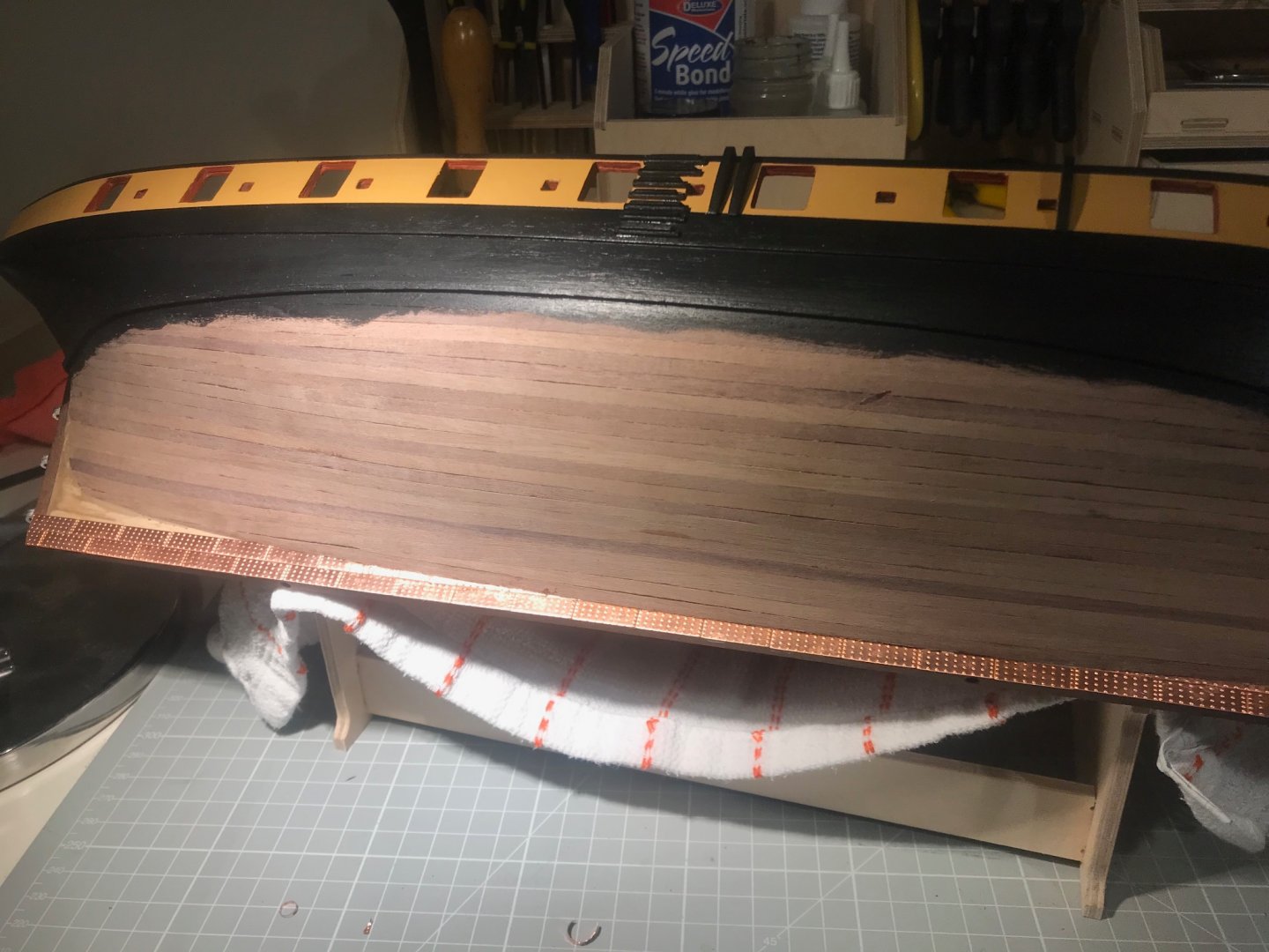
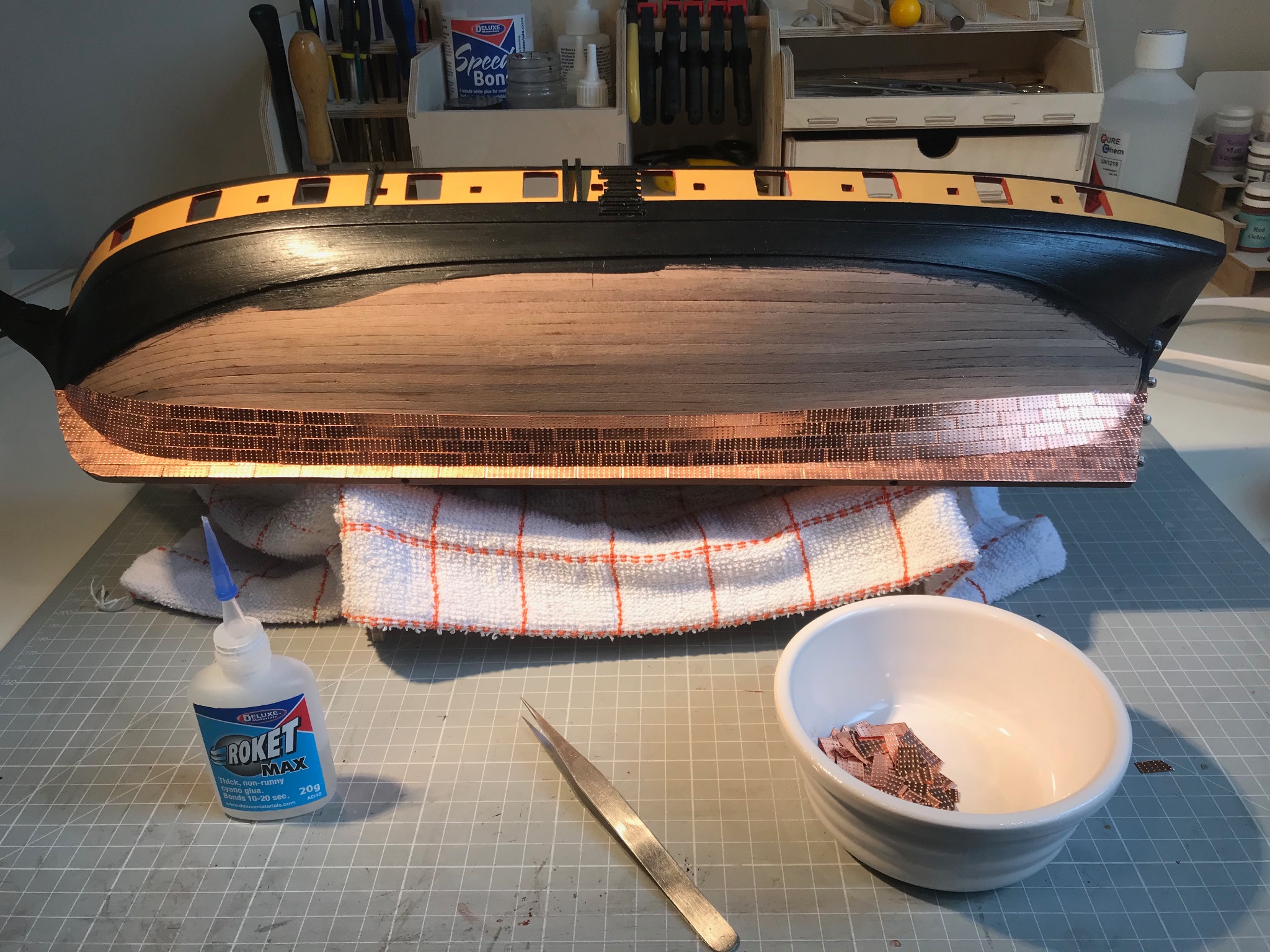
And so copper...
In short, it's a joy. Slow and steady and according to a plan - pretty much the heart-beat of model ship building. I find the copper tiles really quite forgiving:
- nicely annealed so they bend very easily,
- cut with a small pair of scissors,
- the rolled edges are very helpful with slight gaps, since the reflections at the joins make it very hard to detect glimpses of walnut
- with two dots of medium-gel CA they "float" about on the hull surface waiting to be aligned
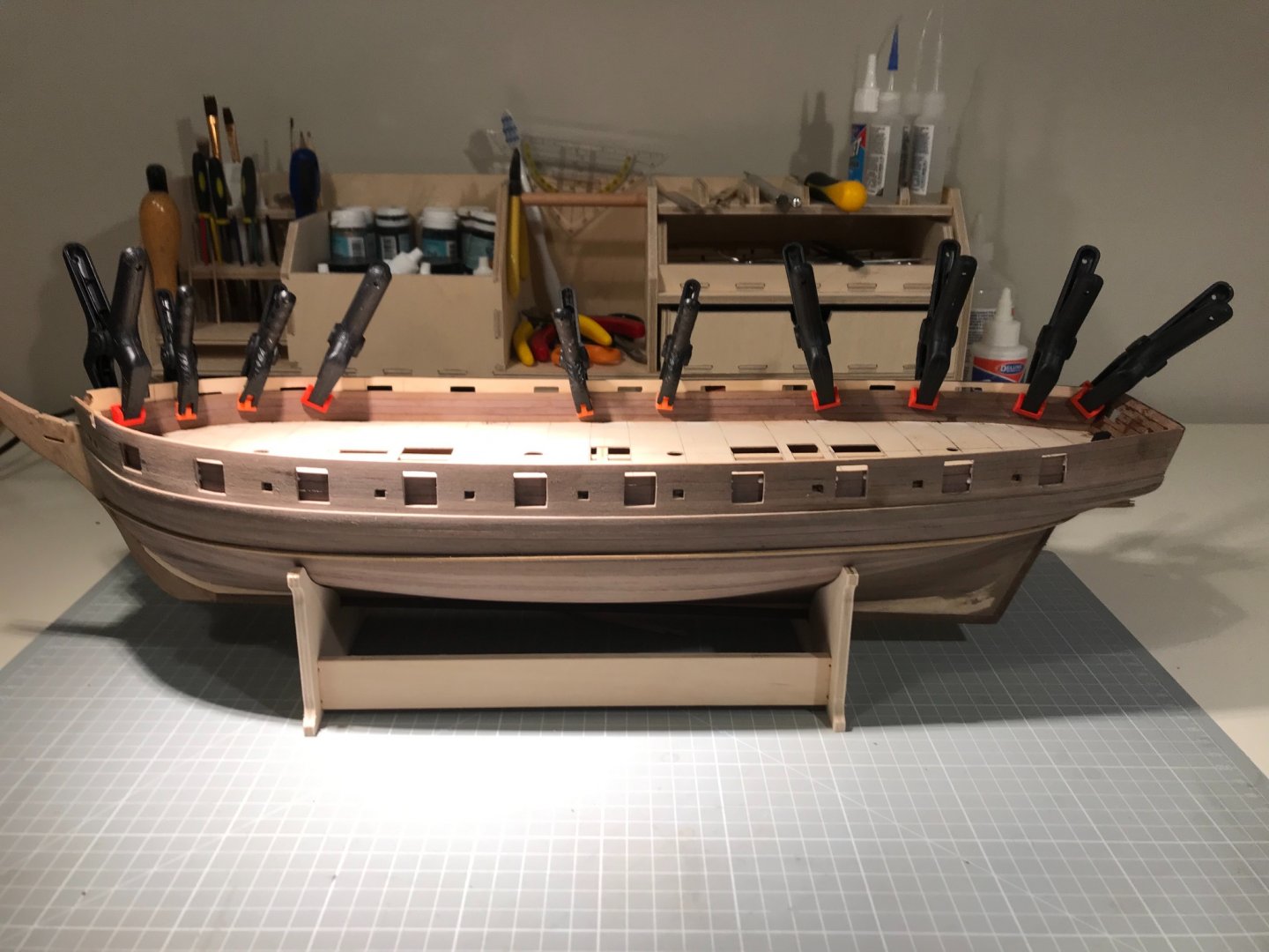
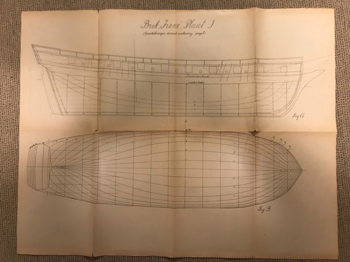
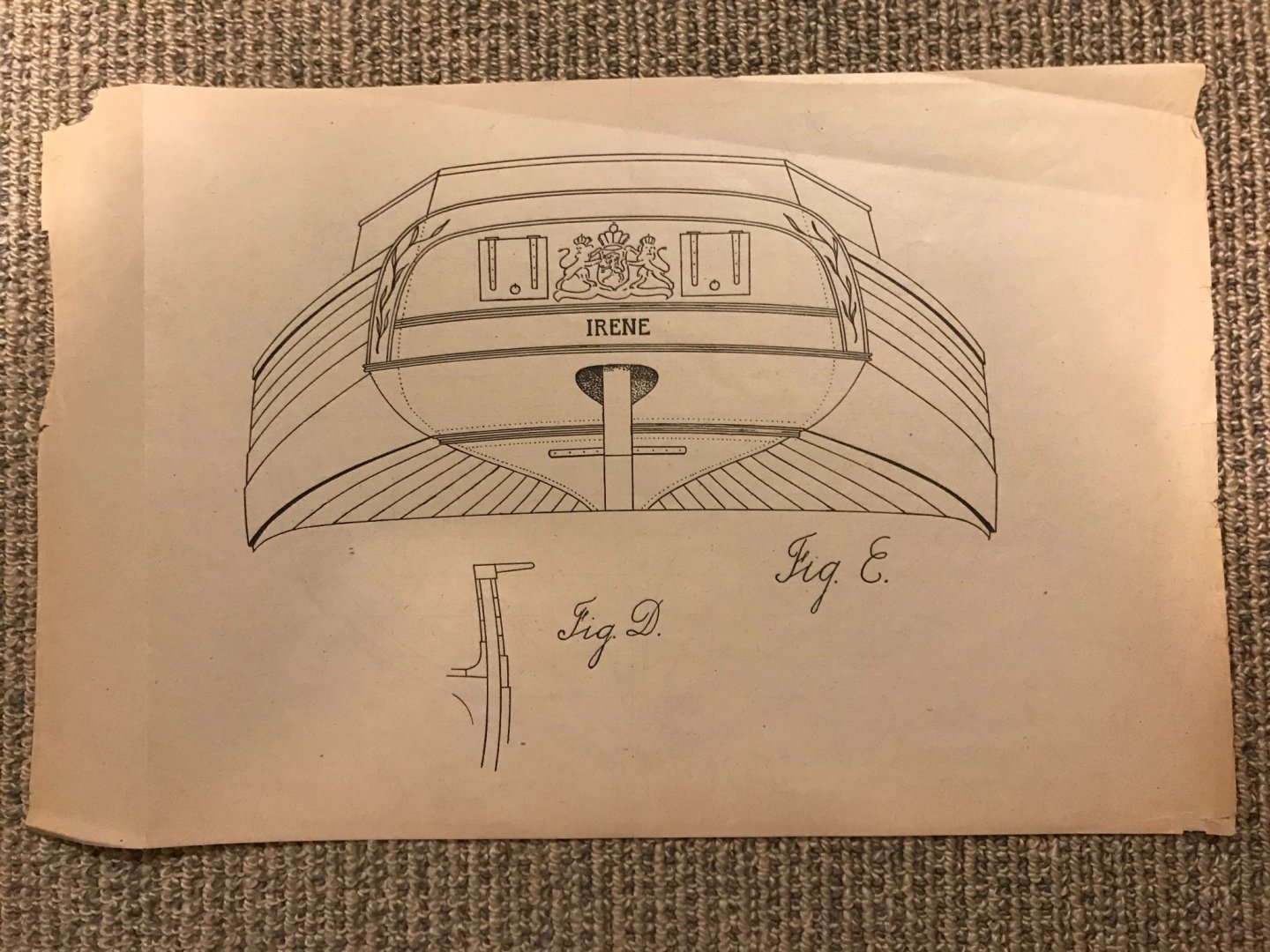
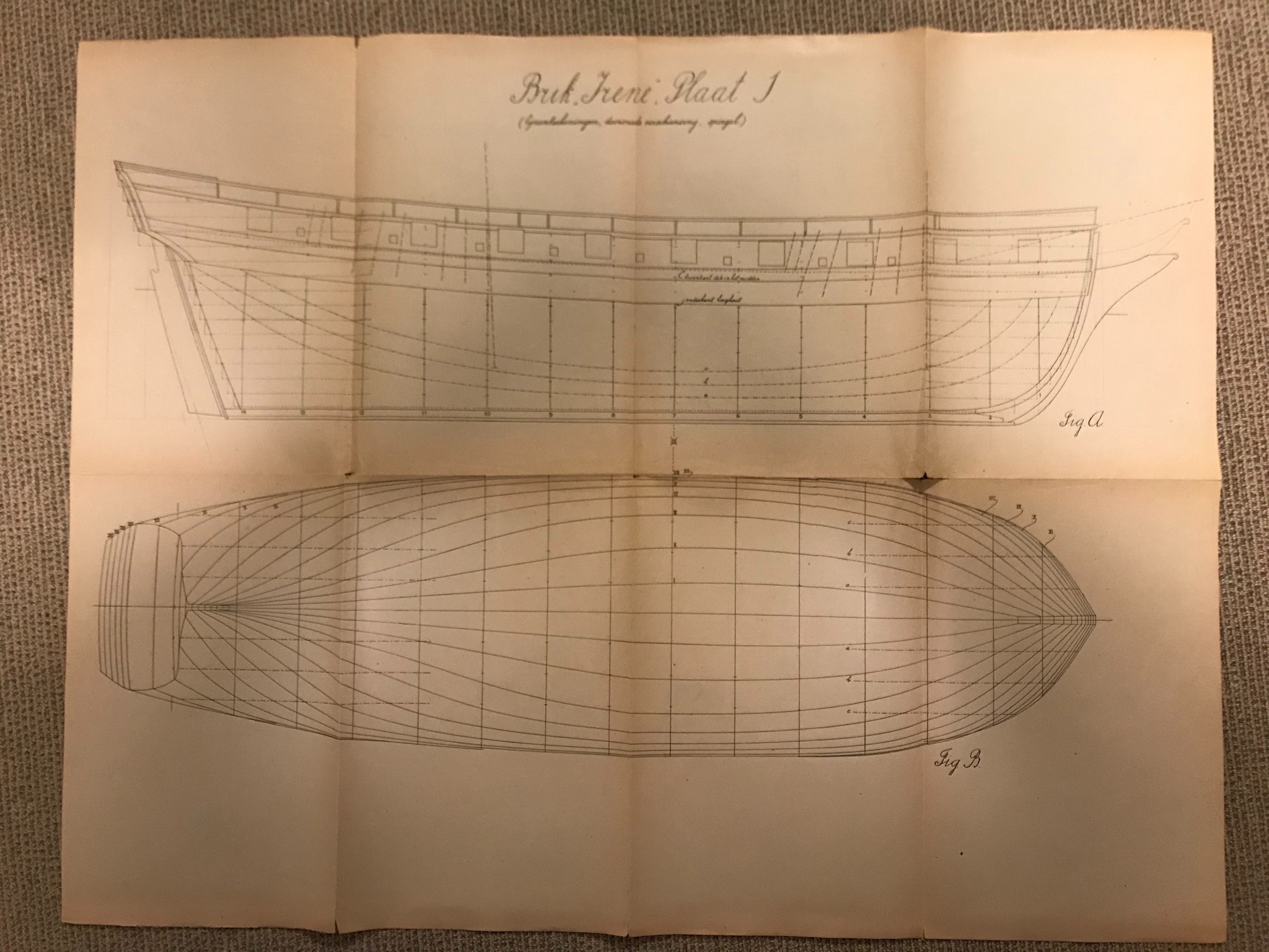
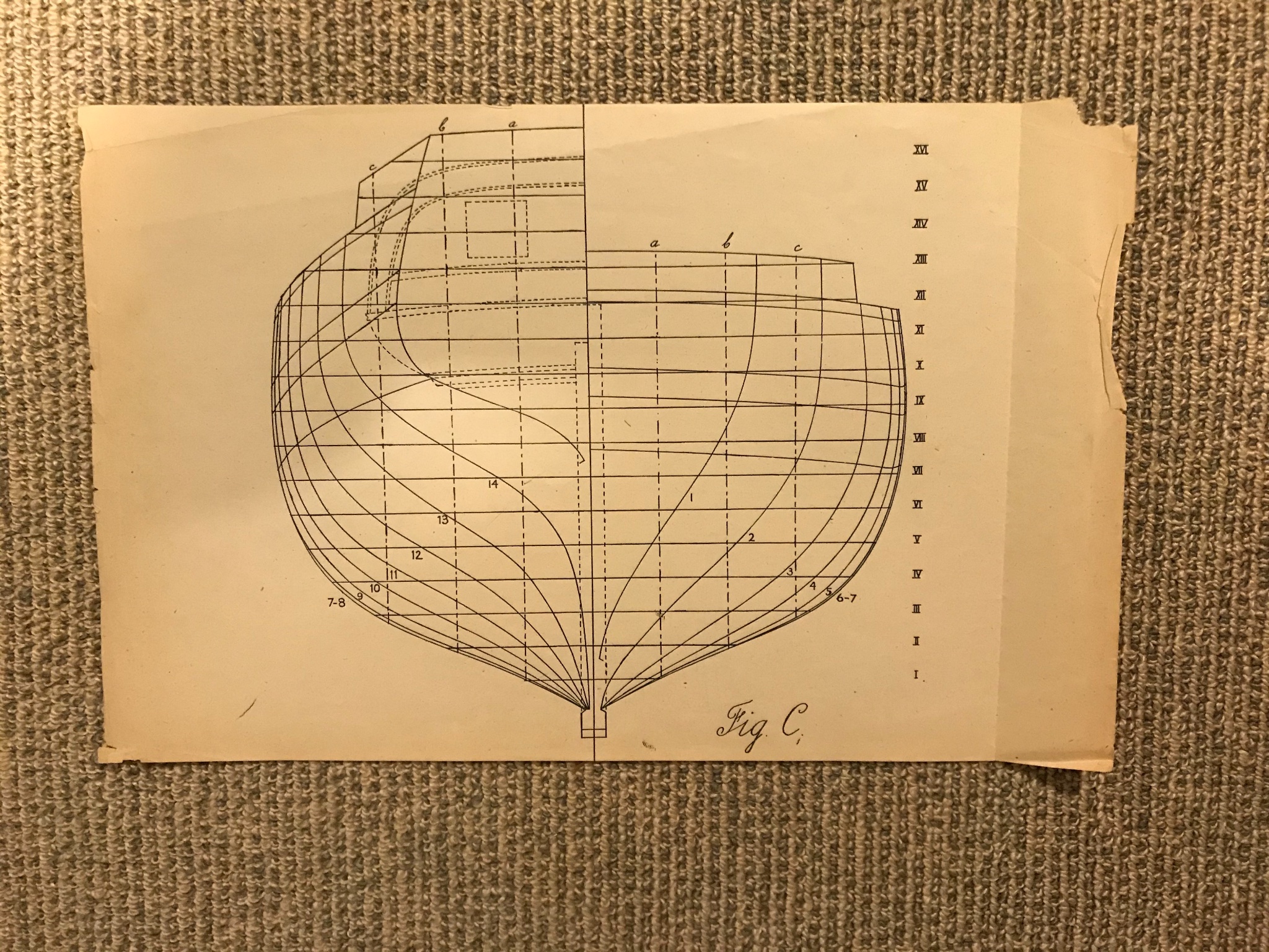
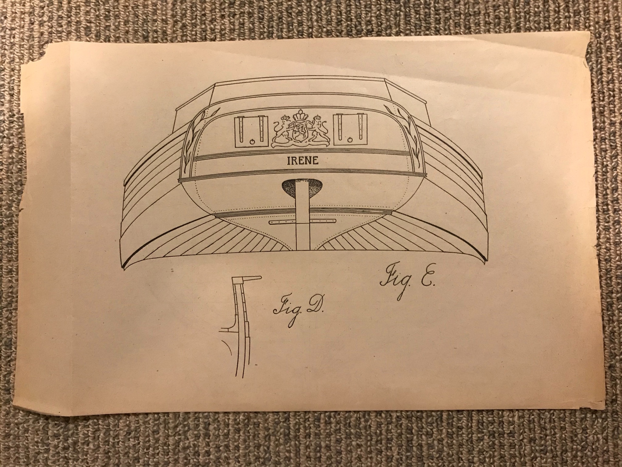
And the plan? Broadly inspired by the Petrejus' drawing in his incomparable Modelling the Irene (as an aside, if, like me, you are new to modelling, this book has such a wealth of beautiful line drawings, that it doesn't matter what you are trying to build, from wherry, to four-decker, there is so much to be learnt). Anyway, his plan...
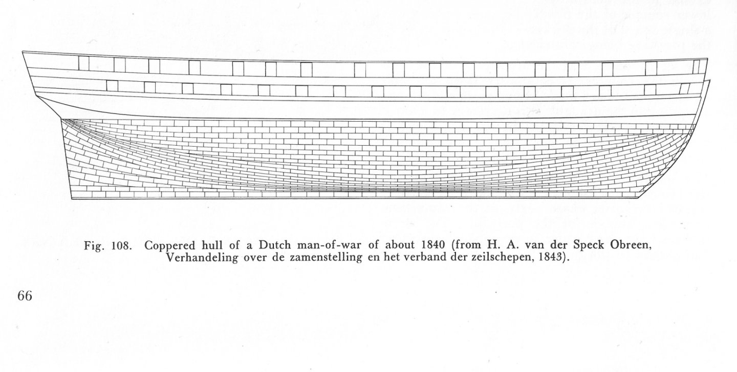
From the keel up he shows the copper sheets laid following the natural run of the hull until about the belly-line of the hold (that's my plan), a set of stealers fore and aft before another band eventually meeting a band of two laid horizontally at the water-line. Because the Snake's keel is not parallel to the water-line, I'm not convinced that a horizontal band is sensible, or indeed that steelers for the converging lines are needed.
This is where I am up to. And I think I have decided to carry-on just following the natural line of the hull, meaning that the line of tiles will "droop" below the water-line batten. But I might go and have a look at others' work.

-
-
Hi Jim, I just stumbled on these, and will concur with everyone else - you have an exceptional talent. The thing that most impresses me is the way you catch perspective and line, on objects that have such subtle, graceful shapes ie ships, waves and clouds. And then skimming through again, your use of a splash of colour.
Your paintings of the Arctic convoys bring back memories of my youth - not in the 40s, but the 70s - where they were frequently referenced, and featured in an Alistair MacLean novel (HMS Ulysses, I think). But for all that water-colour and your talent lend themselves to grey ships, grey sea and white wave tops, it is your paintings of sailing ships moored, or near the coast, that have brought me most joy. So let me give you every encouragement.
We know of the great ships of the 18th and 19th centuries as being the largest and most complex machines of their time, but that might lead us to think that they were manufactured in the very methodical ways in which - post Henry Ford - we manufacture most things today. Early in the your posts here, you showed a small painting of a ship under construction at Bucklers Hard, which correctly shows that ship-building was often closer to cottage industry than industrial production. I recently read Peter Moore's Endeavour, whose descriptions of 18th century Whitby (then Britains most productive ship yard), describes ships on props stuck up creeks, rather than the crisp dockyards of Portsmouth. As it happens I'm drawn to both Whitby and Bucklers Hard - I live in Yorkshire, but have family near Bucklers Hard, and am currently building a model of HMS Snake which (I'm tempted to say who!) was built there. So if either of those locations attracts you, please feel encouraged.
Best wishes, and, well, thanks for sharing
Mike
- Edwardkenway, Canute, lmagna and 1 other
-
 4
4
-
A little light relief:
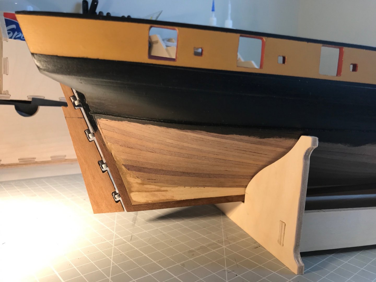
Stern Facia Knees. Quite the easiest installation to date. Angles easy to sand, dab or two of CA, and it's done.

Side Steps and Fenders. Keeping the steps aligned was a challenge, but not really a great one. The Fenders I made entirely from 4x2 walnut strip, rejecting the pair (not six?!) provided in 2 mm ply. Took the radical decision that in my work-a-day ship the 1st Lieutenant would not be paying for yellow ochre paint on parts to be rubbed against quays, boats and other surfaces, or stamped upon by tarry feet. So all are work-a-day black. I'm pleased to have them visible.
Fitted the rudder. A modest challenge since the white-metal castings varied from fair to poor, but most importantly varied. The length of the pins on the pintles needed to be trimmed, the spikes on the gudgeons were elliptical, and the holes in the gudgeons needed drilling out. Squared-up the cutouts on the ruder first, and then glued the pintles in, snug in the top corners of the cutouts. Clamped the rudder in place and then marked a level on the sternpost giving the bottom of each pintle, so the top of each gudgeon. Fixed the top gudgeon: drilled for the locating pin 1.5 mm lower than the marked level. Glued the gudgeon. Checked for alignment. All good, repeated for 2nd, 3rd and 4th. Naturally everything was fine until the last one - as I hurried to get done by lunch. Hole too hight, cutut too short, locating pin snapped. Had some lunch, then carefully remedied.
But now onto some serious stuff. Here's a glint of copper:
- Bossman, Beef Wellington, Sjors and 2 others
-
5
-
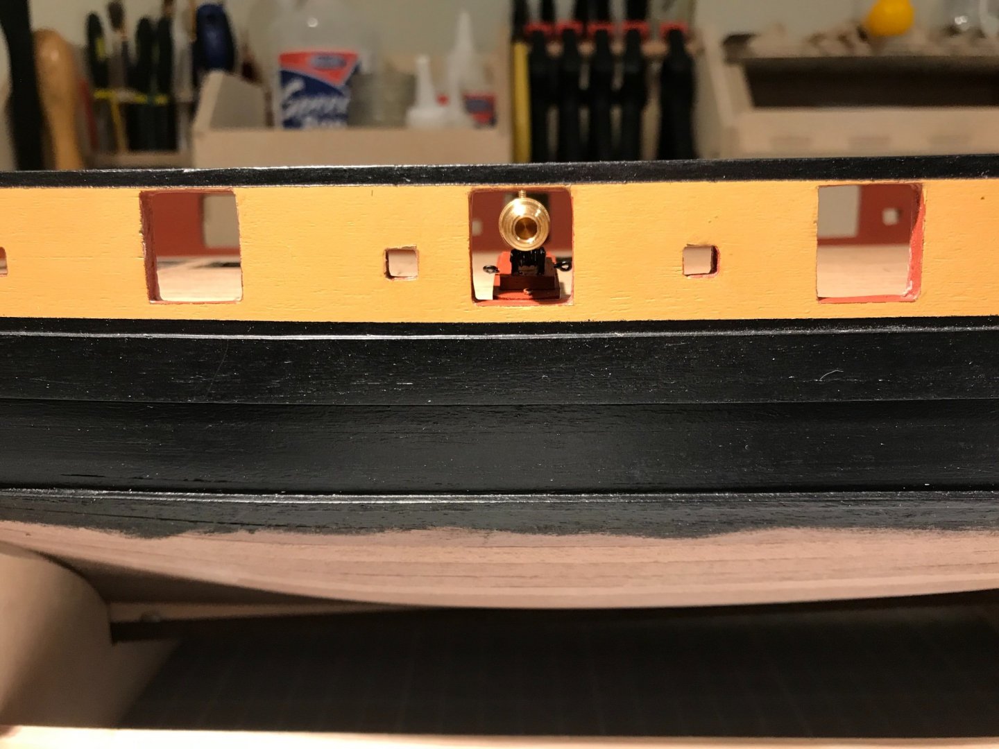
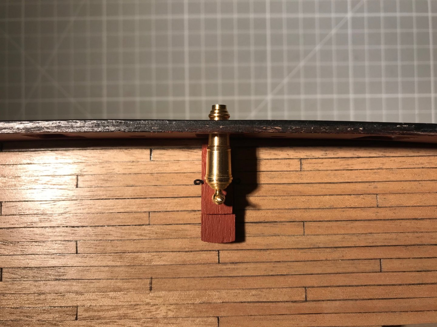
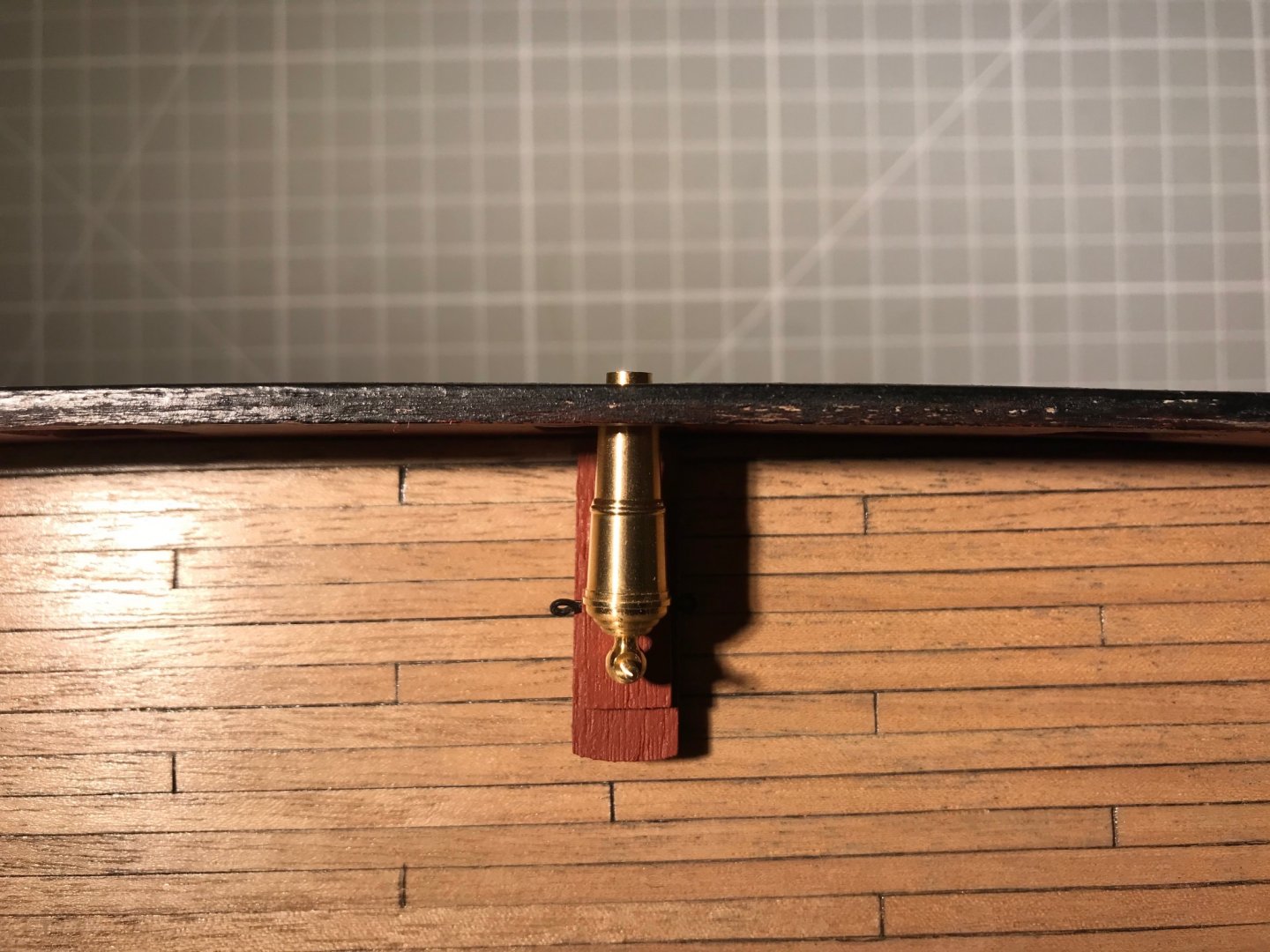
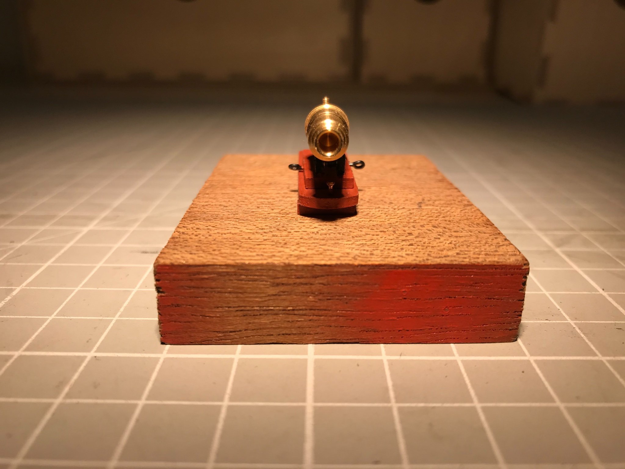
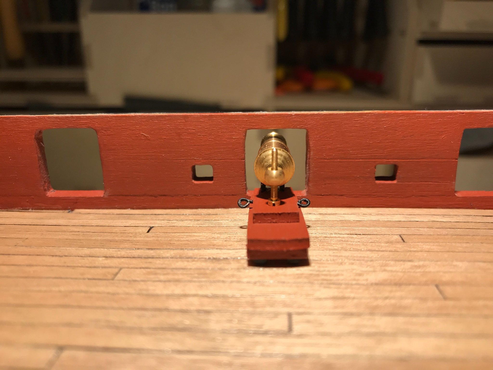
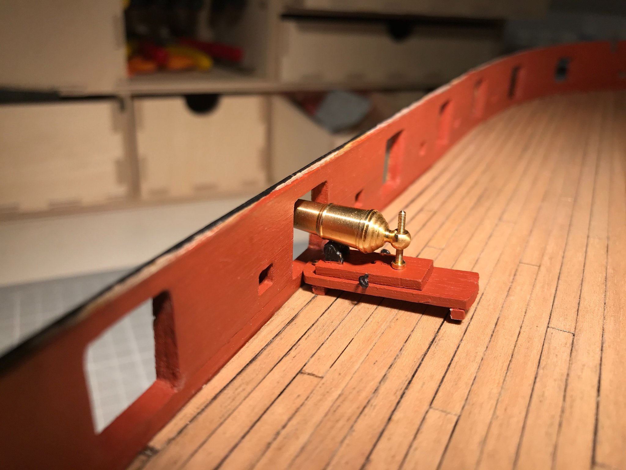
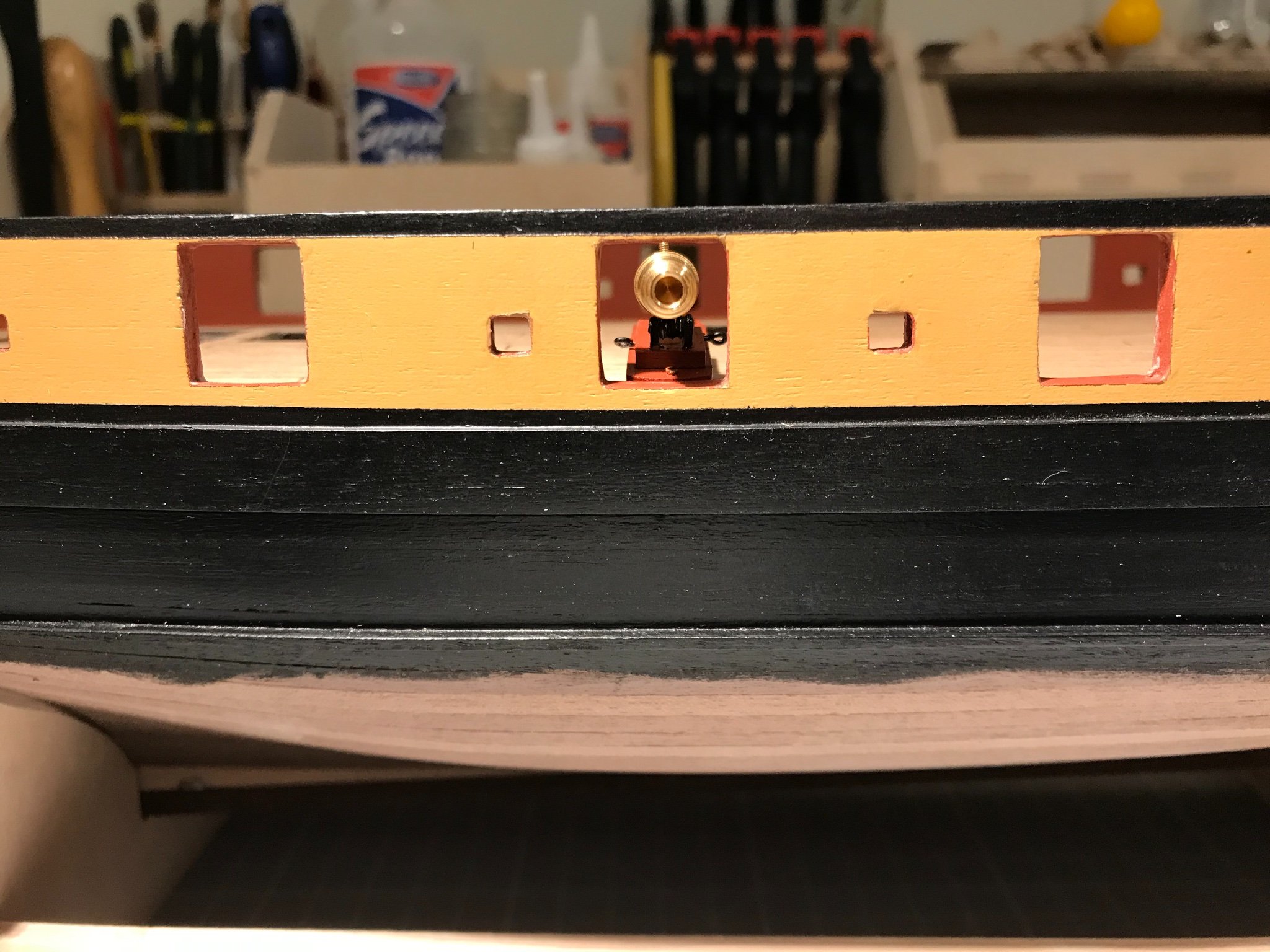
So, to assemble a carronade and offer it up to a gun port. All reasonably straightforward, apart from trimming the photo-etched (PE) parts. I painted all of those black (I might chemically blacken them in the "production" run - and I've not treated the barrel at all - it will be blackened, assuming I can follow the instruction on this Forum)., and while I was careful to pass a 1 mm drill bit through the components designed to act as the pivot - and so sit on a 1mm axle - I also needed to counter-sink them slightly to slide them on. Assembled it and offered it up to the port. As every single perspn who has ever built this model discovers the carronade sits much too high.
Now, there is historical precedent for this set of circumstances:
.jpg.89a759aed8ea2643a228c7d5ec40742a.jpg)
It seems that Scorpion had her carronades set too high - the bed on Scorpion sits above the port sill, and below on Cruizer. You can see, also, that in this case both ships carry their carronades inboard, with a pivot set in the deck. And so, like everyone else I set my carronade on a block, though I did add a pin for verisimilitude.

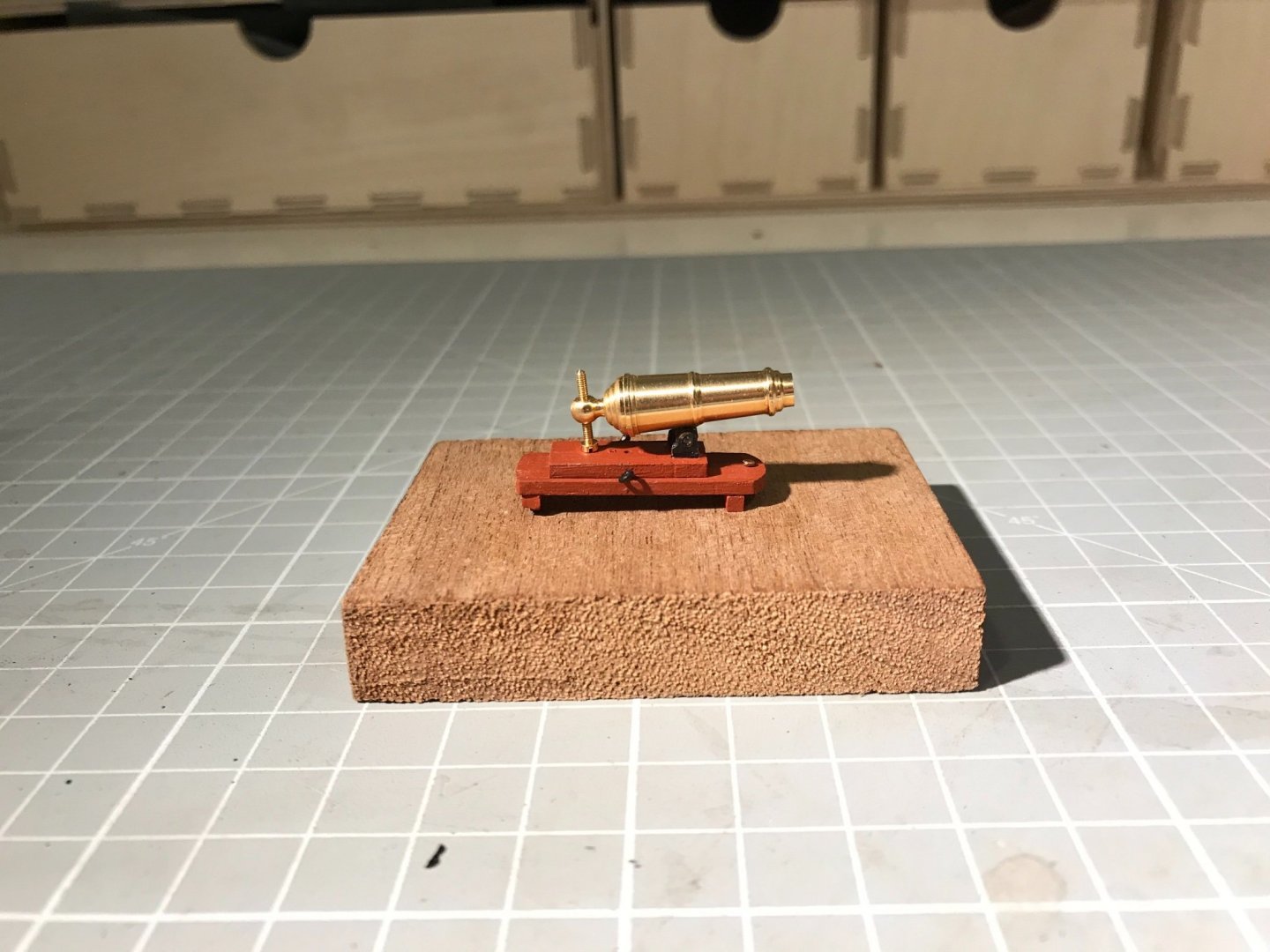


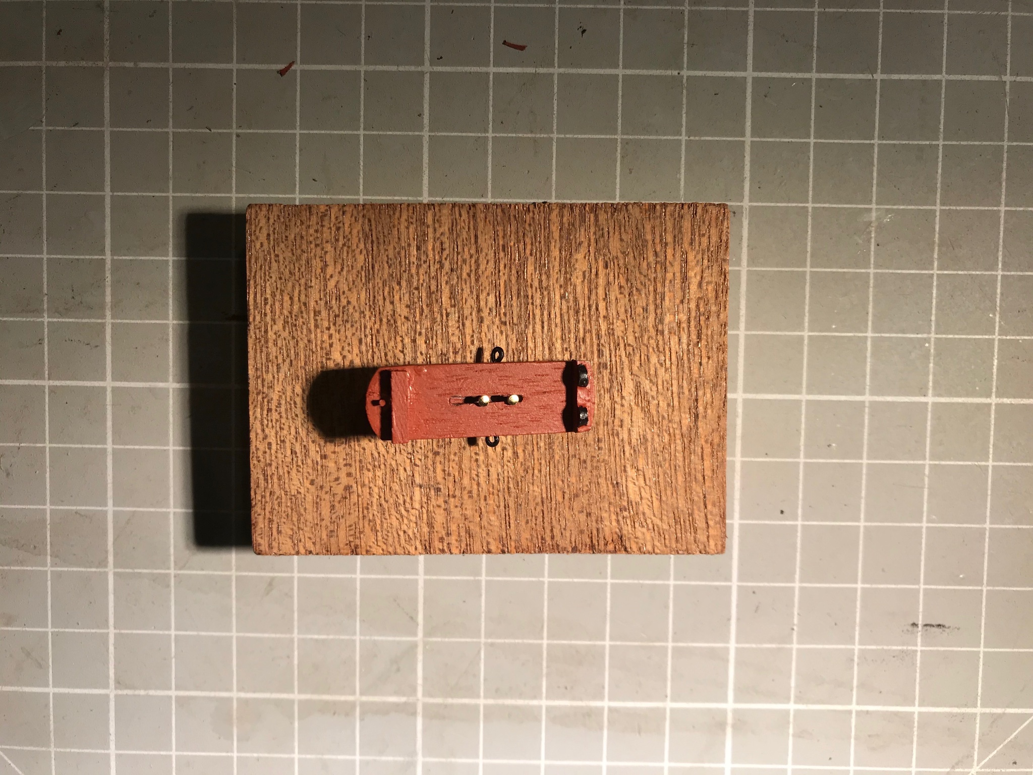
I also, for experimental reasons attached the slide with a pair of pins allowing it to slide. You can see the underside in the first photograph below, and then in the two overhead shots see the result with the gun run out and run in.
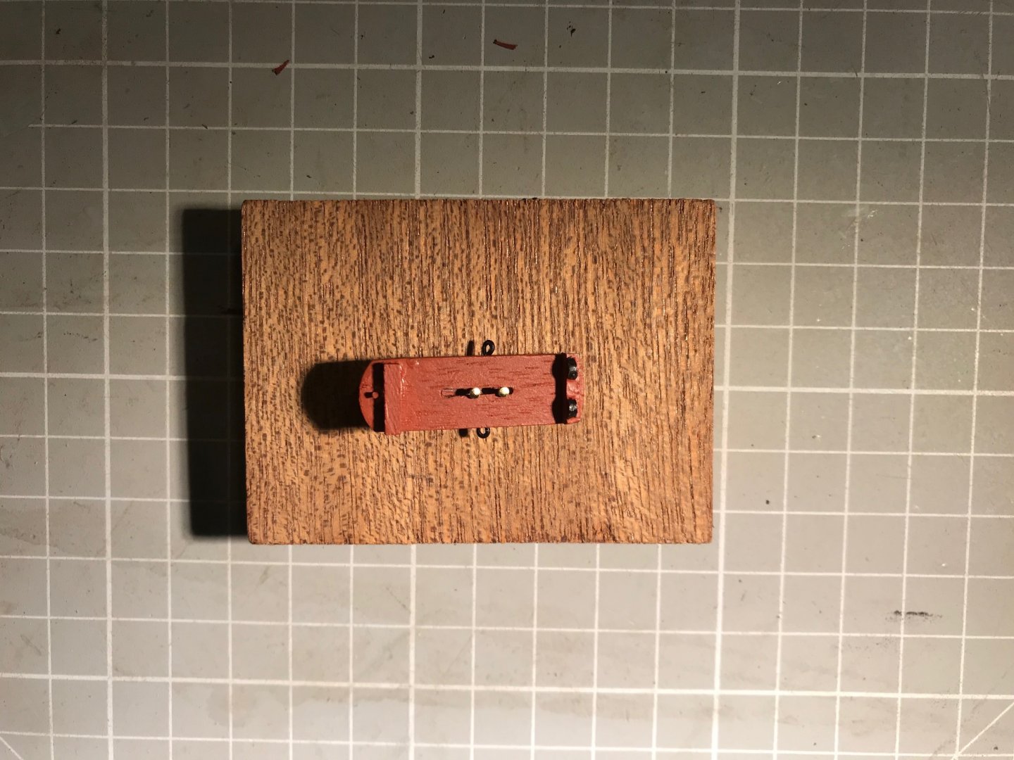
The pins have to be separated to make the slide move parallel in the bed, which means the range of movement is not great. I expect when I come to install the guns I will pin them - with one pin visible as a pivot and the other attaching slide to the bed, and then passing into the deck.
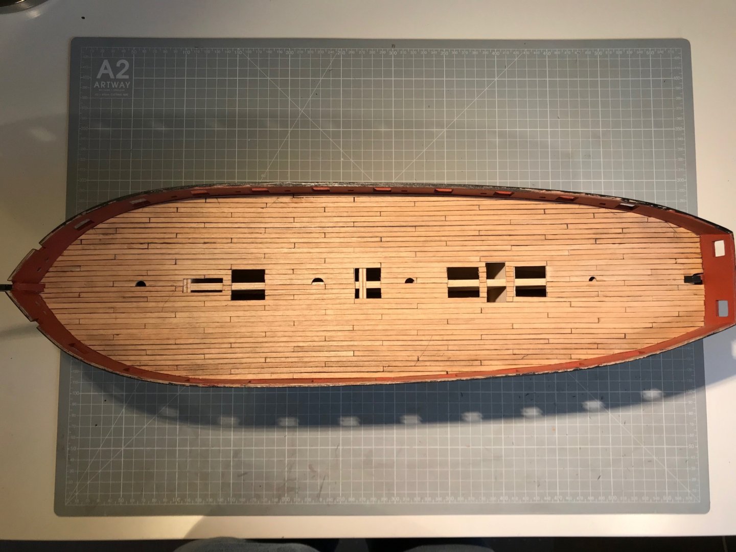
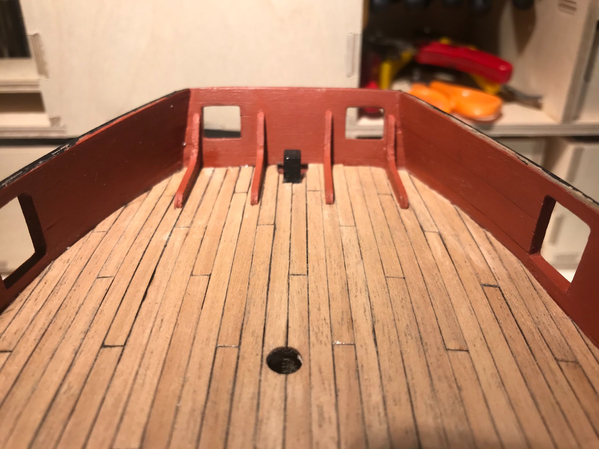
On a final point, the deck planking looks fin in these overhead shorts. Don't think I will do the port sills - the Cruiser model from the NMM does not show them. Not sure what I will do next - certainly not the fore and aft platforms, or the bulwark capping rail as suggested in the book of words. So I'll check to see what others have done. Hope it's not the copper, as I'd like a week or two of variety after the deck planking.
- Beef Wellington, BenD, chris watton and 1 other
-
4
-
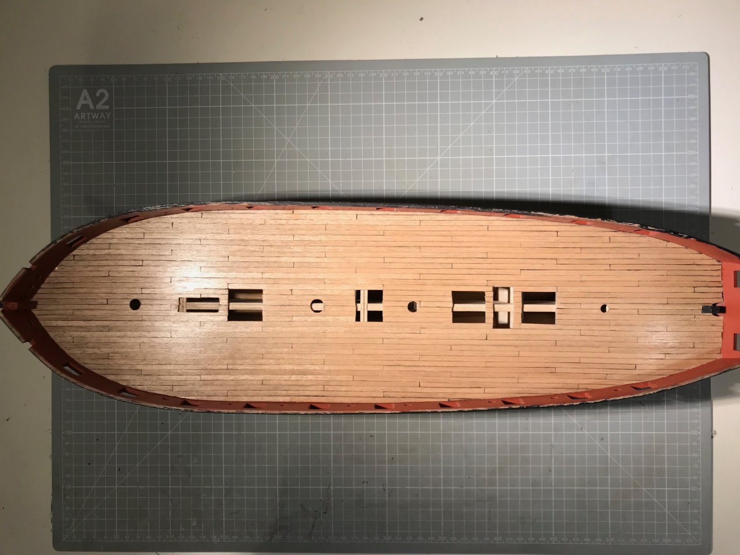
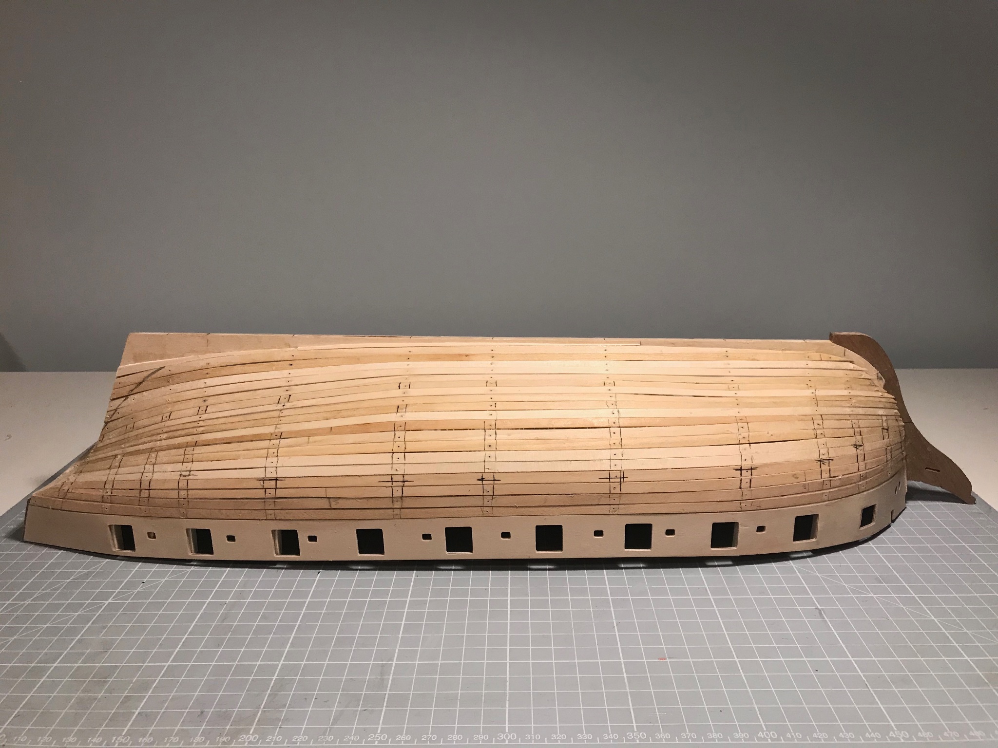
Deck is fully planked. Have you noticed that the go-to explanation for difficulties in model-ship building is quality of strip wood? Well, let me tell you about the Tanganyika supplied with the kit. The good points are that I like the colour and the grain very much. That's it! It's a bit shaggy, but a little sanding fixes that. The real issue is that quite a lot of it is seriously warped (in the plane of the deck), but worst of all it is different widths, and I think I had one strip that turned out to be a different thickness.
Keen readers might remember that I marked-out the deck beams following the NMM plans and aligning plausibly with the hatches, masts etc. That gave me planks of roughly 12 cm in length that all needed to be laid parallel and snug against each other. Doing that with warped strips of random width was not a lot of fun. There is also scarcely enough timber supplied so there was no choice but to mix and match different strips. The result, before sanding is this:
At this point I half-imagined I would either rip it up, or plank over it. You can see seams (and gaps) or random thickness and a lot of smudged pencil.
Let me explain: the approach I took was to bevel each strip so the top-side was slightly narrower than the deck-side, and then blacken the chamfered edges with a a very soft 6B pencil. I would then present the strip to the marked-up deck, and mark where to cut the strip. This I did in a miter-box with a razor saw. I then chamfered and blackened the ends of each plank. I used a thin line of thick CA glue (Deluxe Materials Roket Max), which gave about 5s for fiddling.
Problems: I bevelled with a sanding block while holding the strips in a pair of smooth pliers, but the strips are very floppy so getting a constant angle doesn't seem to have happened (but Tanganyika is not suitable for planing), the graphite from the pencil goes everywhere, but the really tough bit is getting the planks parallel and snug when they are warped and and of random thickness (I'm complaining too much now, but it was very frustrating).
Anyway, I sanded and varnished.
And while I'm not delighted, once the deck is fitted out, I'm guessing the caulking lines won't be so obviously varied in thickness, and I really do like the colour - nothing flashy on this very workaday ship.
If I were doing this again (I wouldn't, I'd buy one of @chris watton's new creations with etched decks) I would pay much more attention to the width of the strips, and experiment in advance (and so have plenty of timber to start with). I still think bevelling and soft pencil should work, but I would use some kind of clamp to hold them while bevelling, and probably not cut individual planks, since it turns out that with a chisel-edge scalpel you can cut a little v to simulate a butt join. I also wouldn't cut our the hatches, or interrupt the run of the planks for them.
Next up "the lower quadrant sills", though I had better check that the fancy turned-brass carronades mount properly (spoiler alert - they don't)
- Beef Wellington and BenD
-
2
-
Truly exceptional Jason. The quality of the final model, and your well-documented journey of learning and discovery, are inspirations to anyone, like me, following in your footsteps. And while I have already learnt a lot on technical matters, I think the biggest point is your patience, and obvious enjoyment of small, individual pieces of progress. I have no real expectation of replicating either the technical proficiency or the patience, but I know I'm already doing a better job for trying.
A final point: this won't be a final point! I do hope you are still active on the forum so I can ask many questions in coming months and years. Perhaps you might like to fully rig your Jason - that will keep you active on the site.
So, many congratulations - for finishing a project started in pre-history, and doing it in such style.
Mike
- Martin W and Beef Wellington
-
2
-
On 1/20/2021 at 6:58 PM, Wahka_est said:
Impossible to have workplace that clean!

Keep up the good work!
There are reasons for that - first the room is less than 9 m2 in area and second, my working from home desk is immeditely behind me when I’m working on the Snake. So any mess is visible to work mates. But thanks for noticing!
-
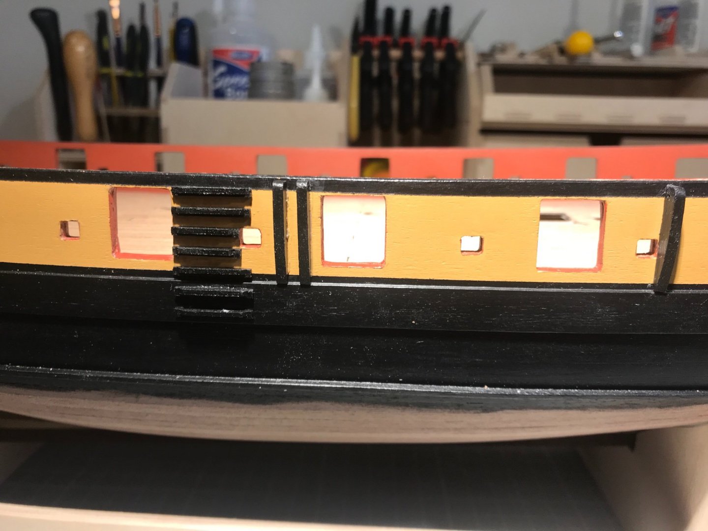
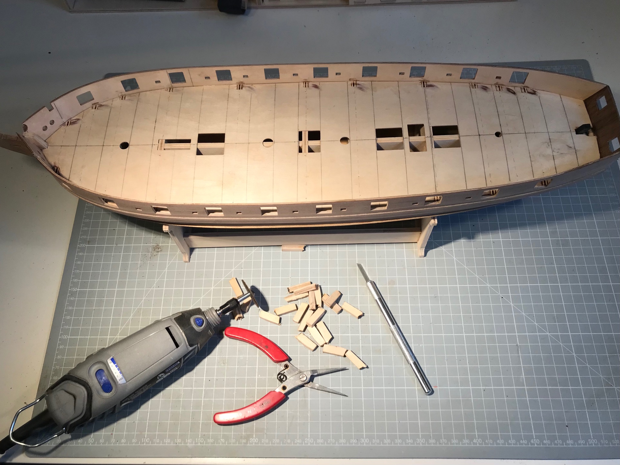
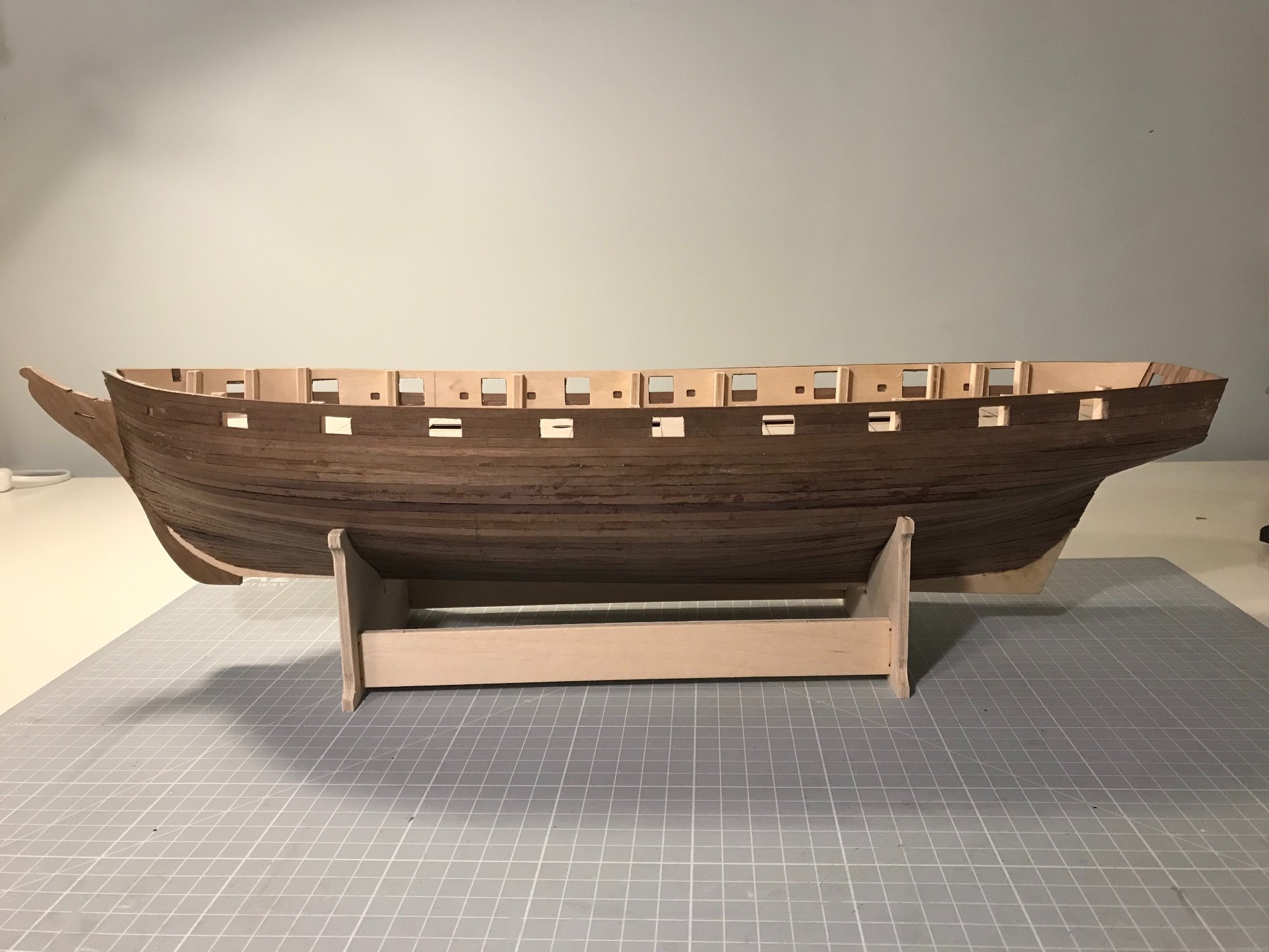
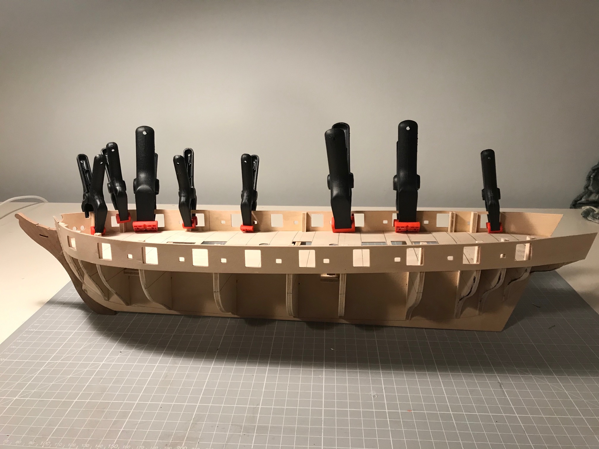
A few steps forward, a few back, and then some more forward.
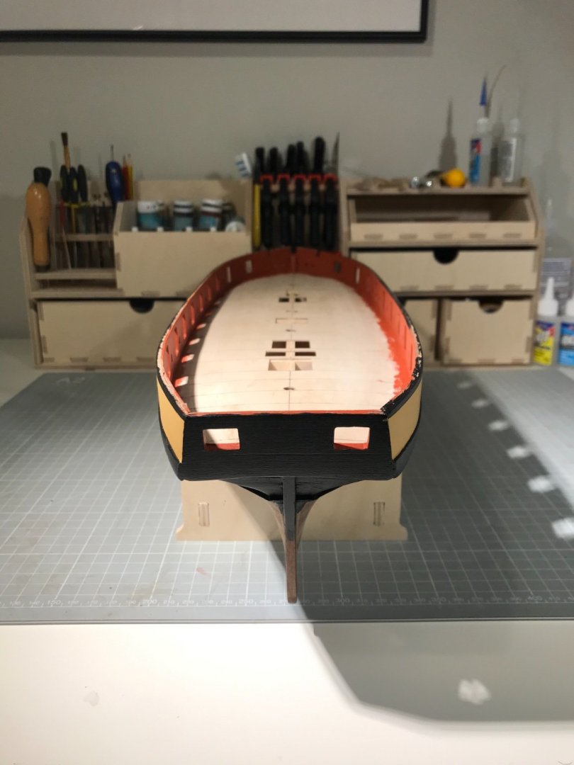
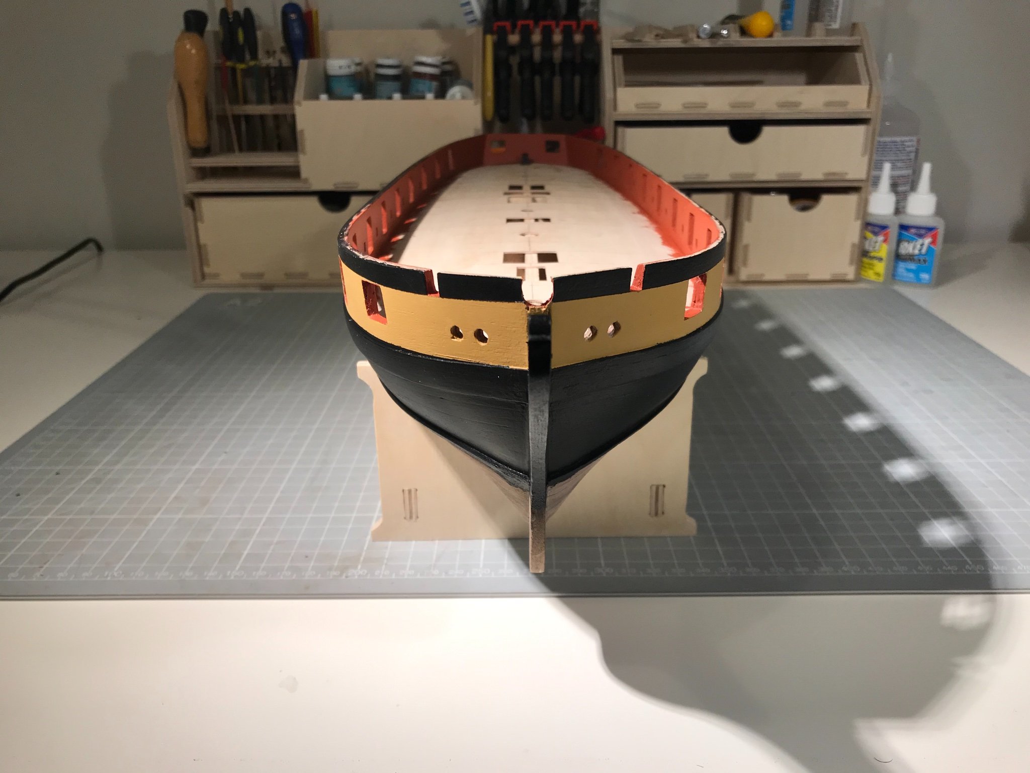
Finished the planking inside and out. Cut out the gun and sweep ports.

The eagle-eyed might spot that the waterline batten is gone. I had placed it using the supplied drawing, matching the position at the cut-water. The more I looked at it, the more convinced I was that it was too high. Checking agains the rudder it really was apparent at the stern. So off it came.
I also realised that I hadn't quite got the line of the port main wale right at the stern (not sure how). Anyway, with much trepidation I trimmed off a lower portion and spliced in a wedge-shaped piece at the top. To my great relief it worked fine. Lessons: pay more attention, and don't be afraid to remedy a mistake.
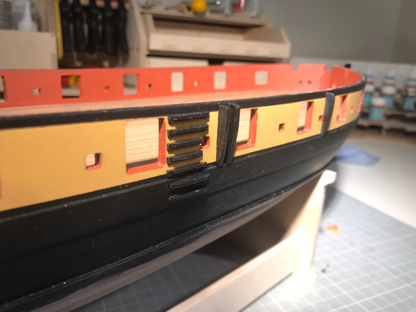
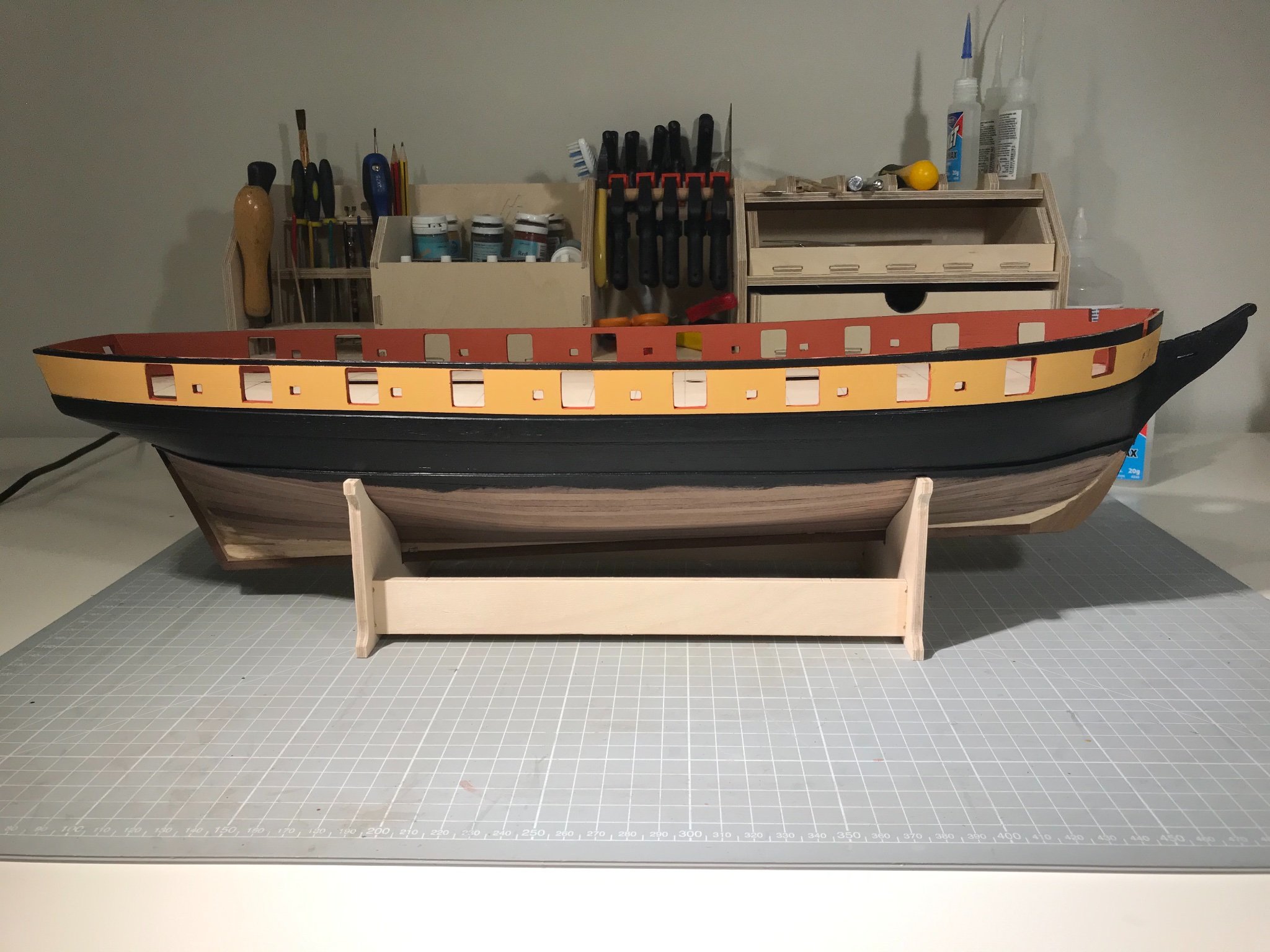
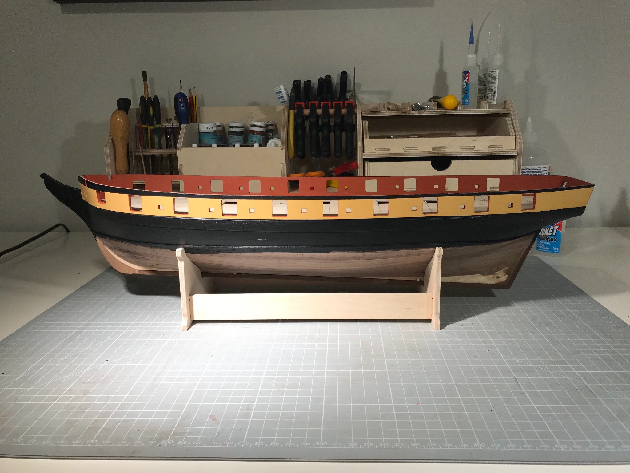
Here she is with the outboard bulwarks painted yellow ochre, and then masked up for the red and black to follow.
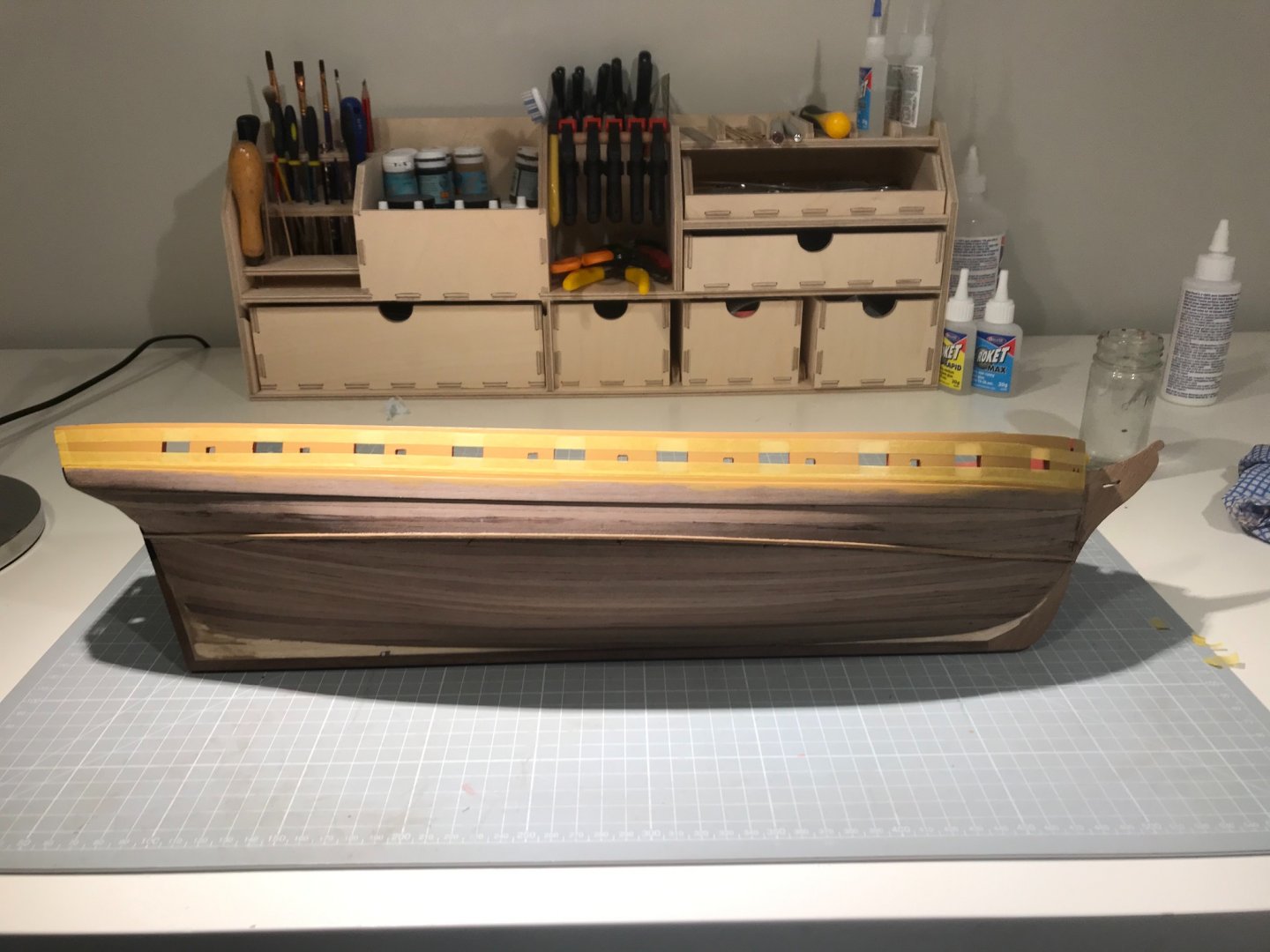
And here she is all freshly painted.


Now on with the deck planking!
- Jobbie, CiscoH, Beef Wellington and 2 others
-
5
-
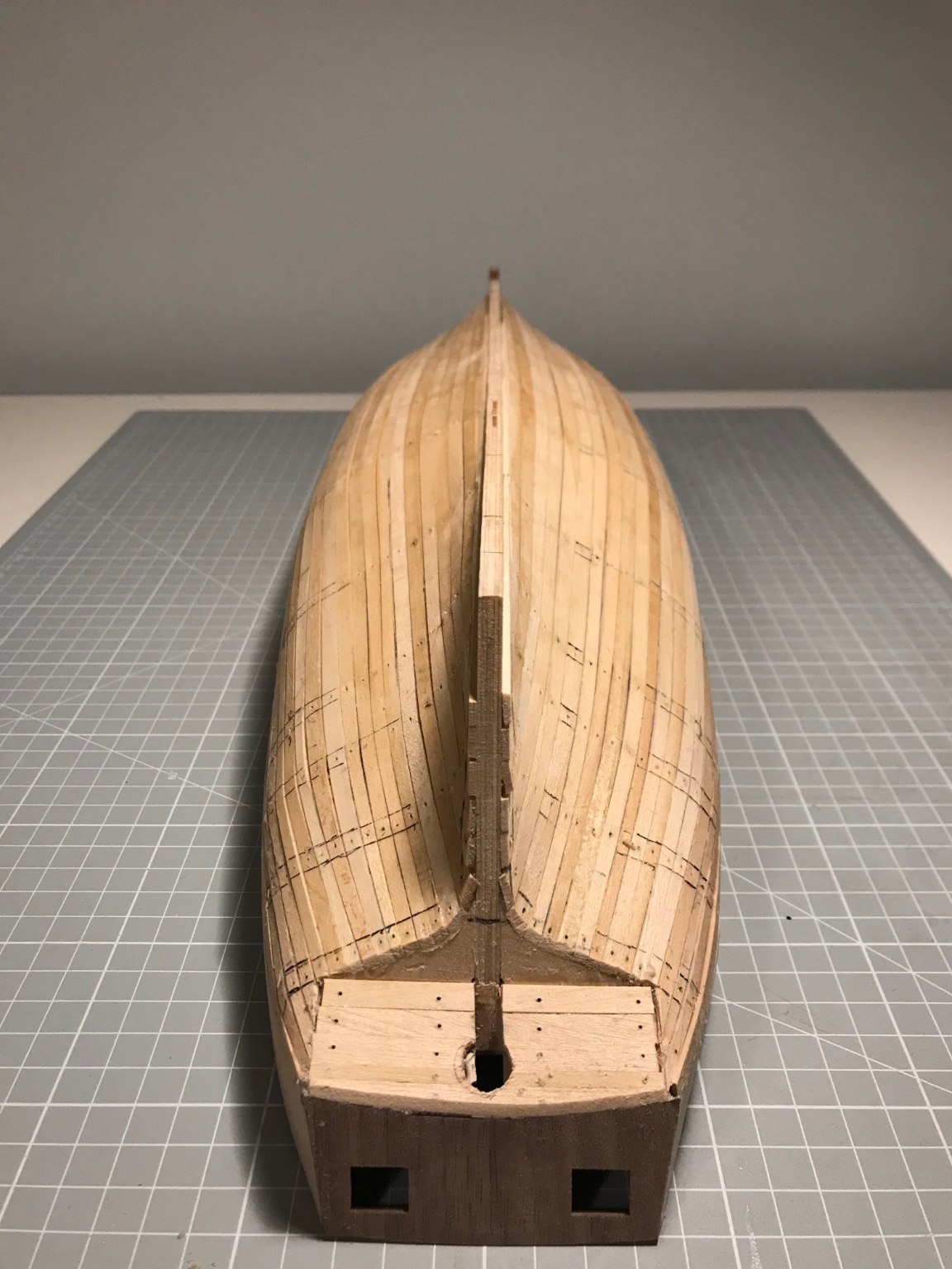
Holidays, 0ºC, occasional snow. Excellent for progress.
Main wale, and water-line batten fitted. Hull sanded.

Bulkhead extensions cut through and plucked out (images of self as Stephen Maturin dealing with rotten teeth)

Bulwark inner planking largely done.
- Beef Wellington, Jobbie, jwvolz and 2 others
-
5
-
Breath-taking, as ever, Jason. I need to install the catheads in the nearish future and was wondering whether to drill them out. I see you have gone beyond that, but apart from the end of a pin proturding I cannot see what you have done. Is there a sheave in there?
-
On 11/30/2020 at 12:47 PM, jwvolz said:
Glad you found a nice copy Mike. It's a great resource on this build, and for the period in general.
Did yours come with the plans? That's the one thing I don't have.
Well, I knew there were some plans slipped under the dust jacket, but I only got round to checking them today - what glory!

- p.hoek, jwvolz and Beef Wellington
-
3
-
-
Hi Liam. I’m building a Snake at the moment, a couple of hundred miles north, and about 2 months ahead of you. You can see my build log here:
I give some links to some builds more advanced in time and knowledge than me. They are well worth browsing if you haven’t already. I’m having a great time, and learning a lot.
Have fun. Mike
-
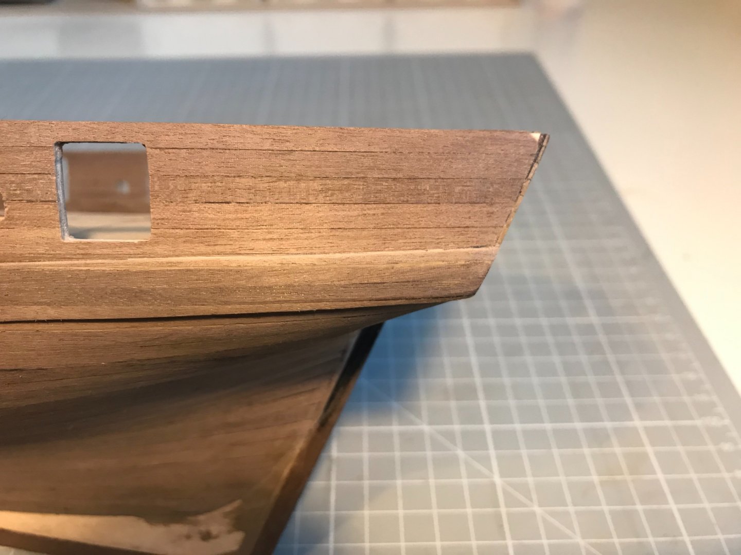
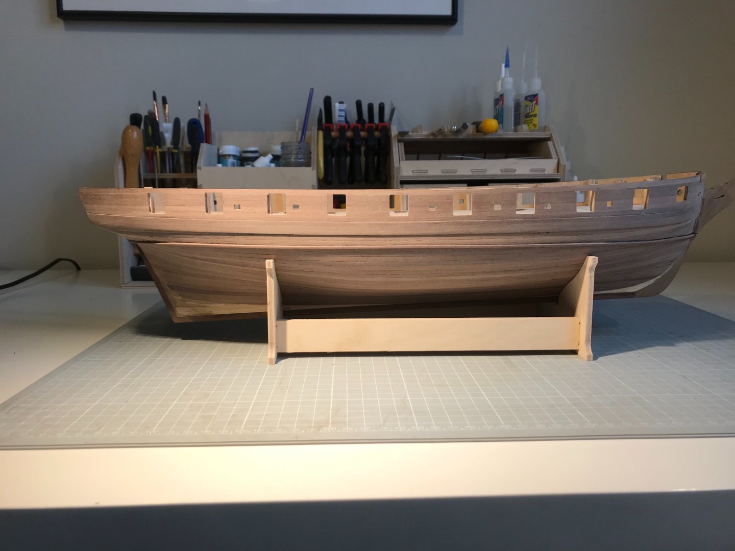
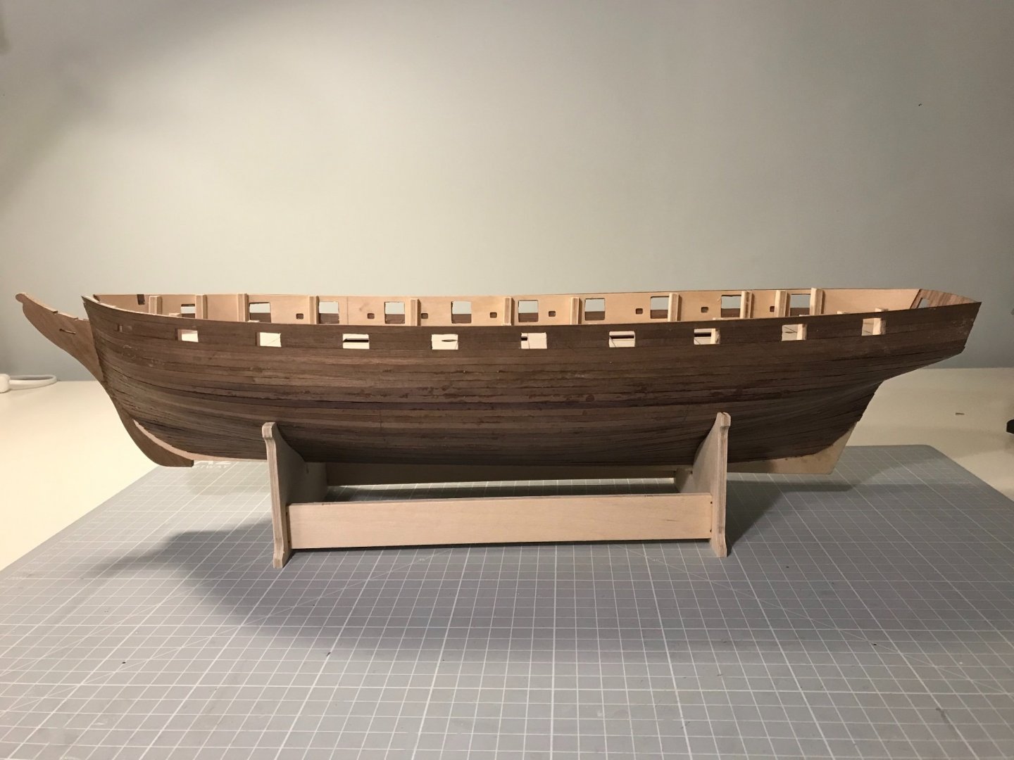
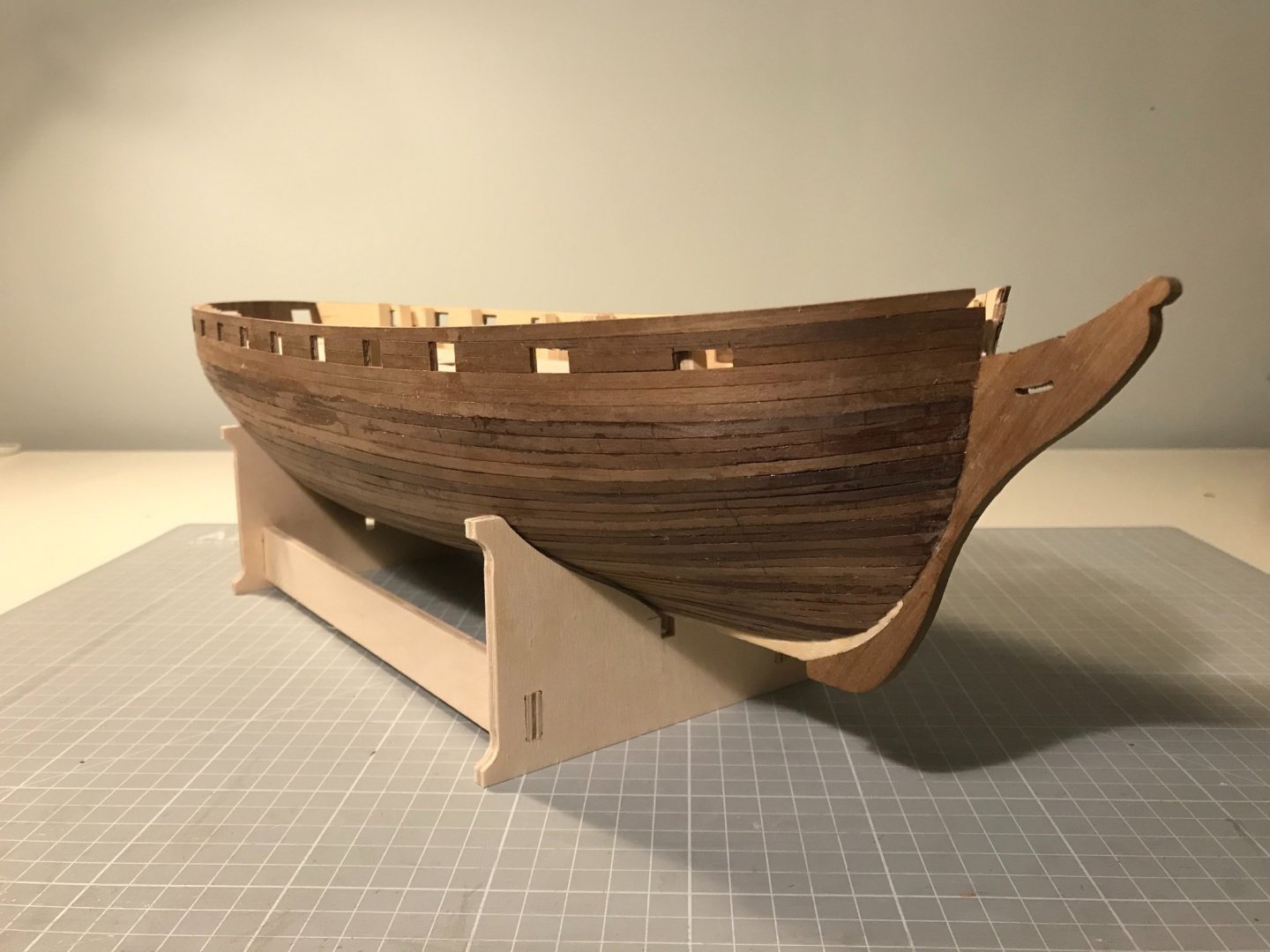
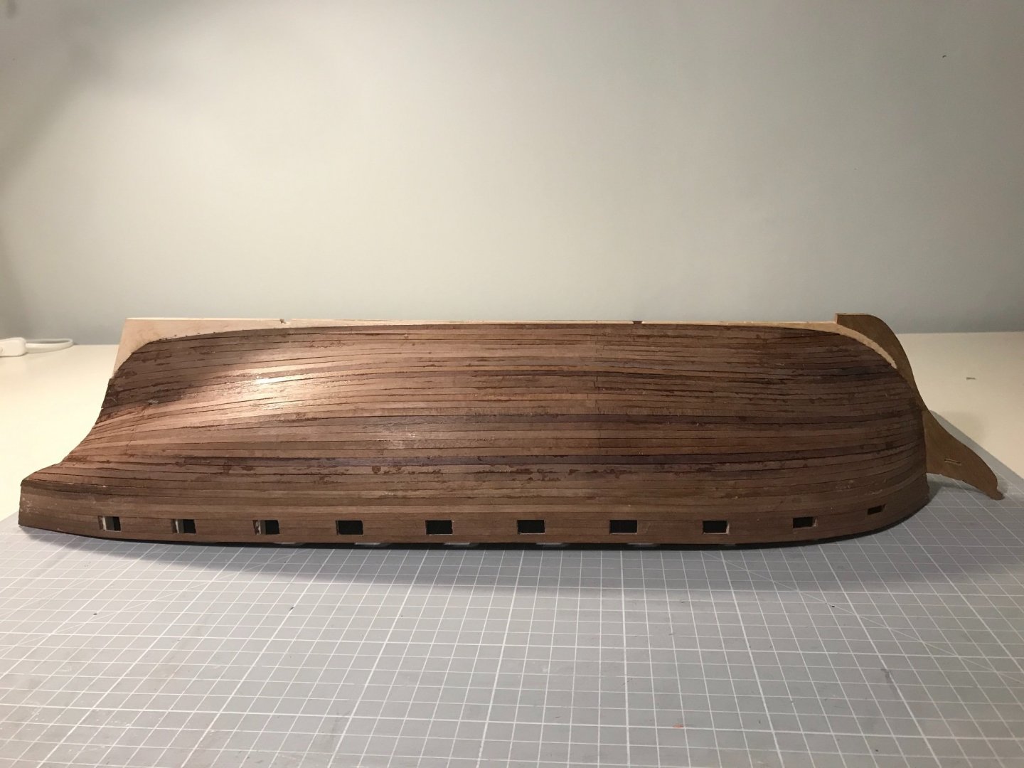
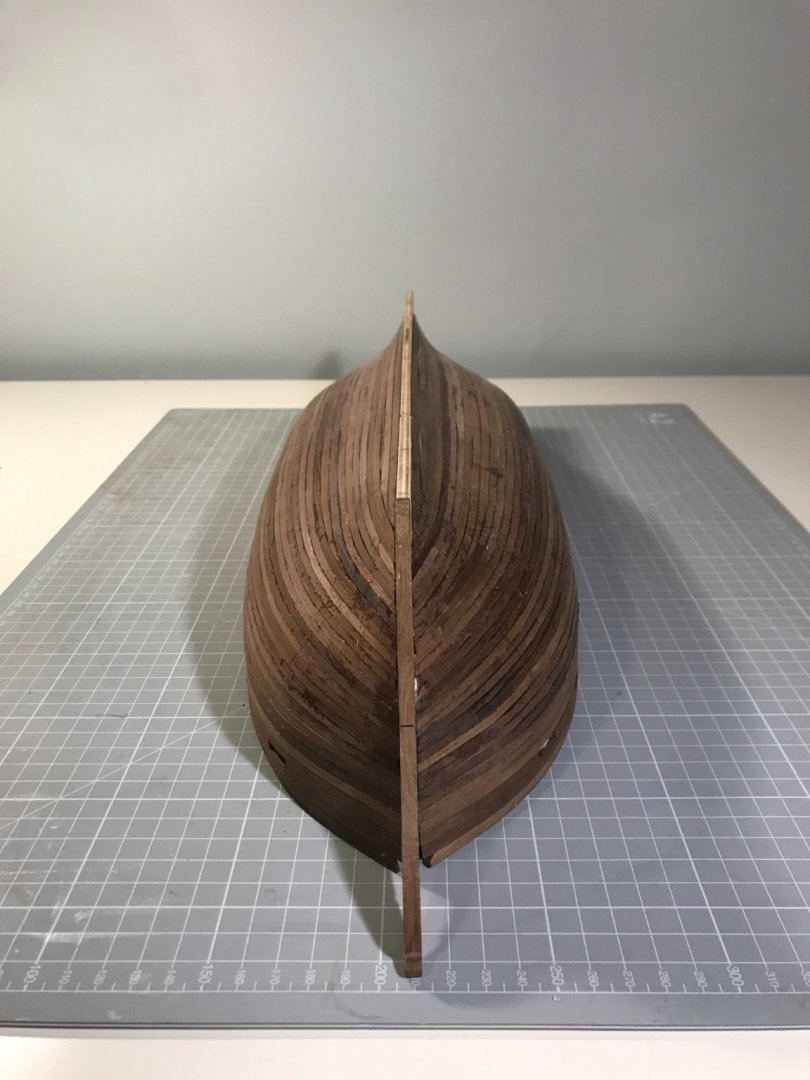
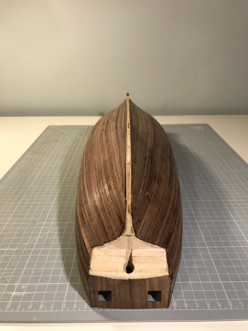
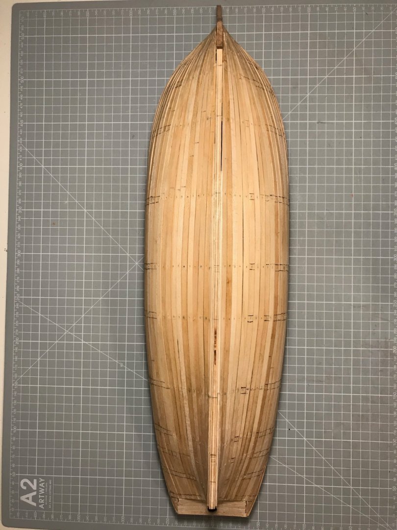
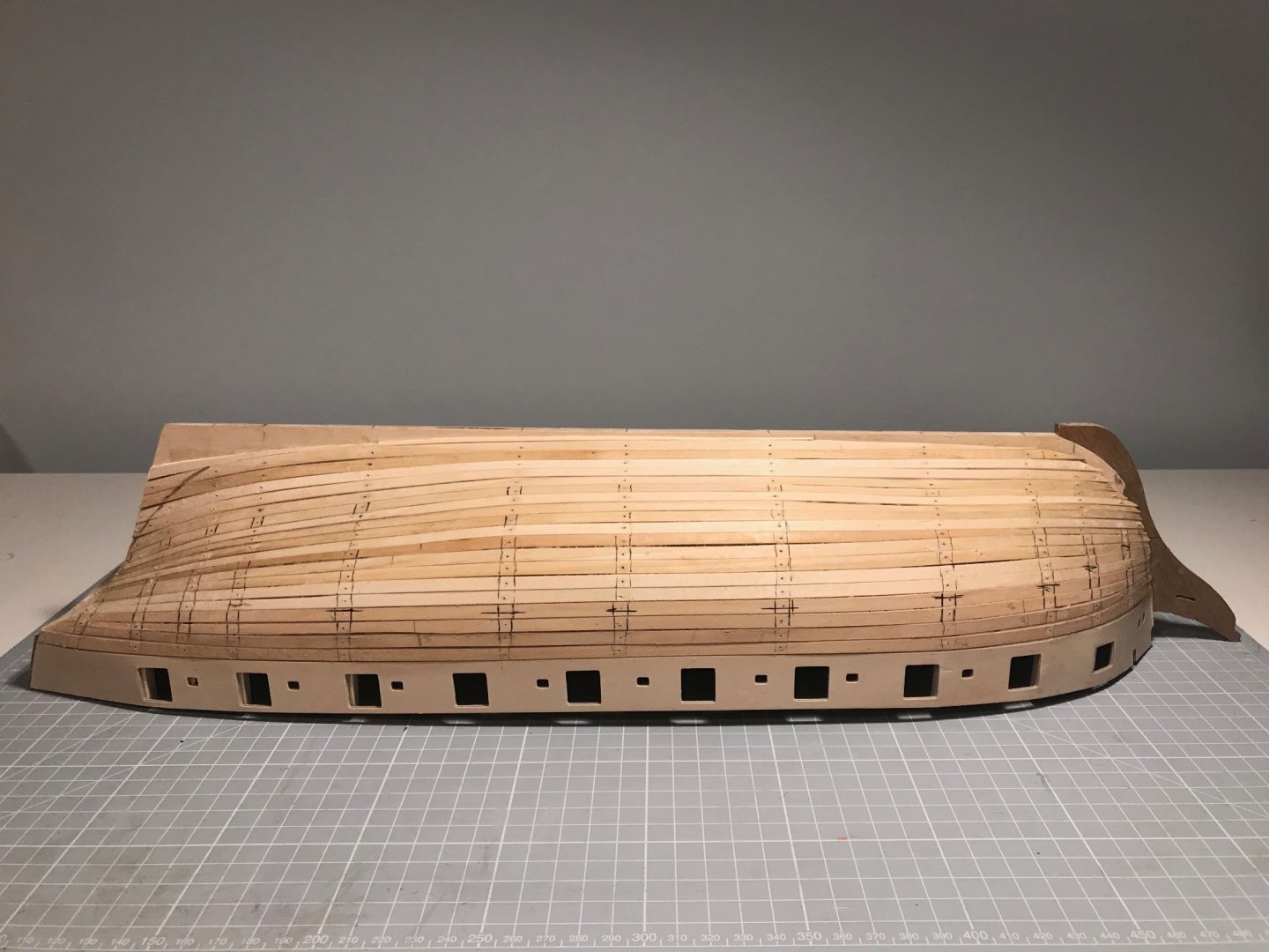
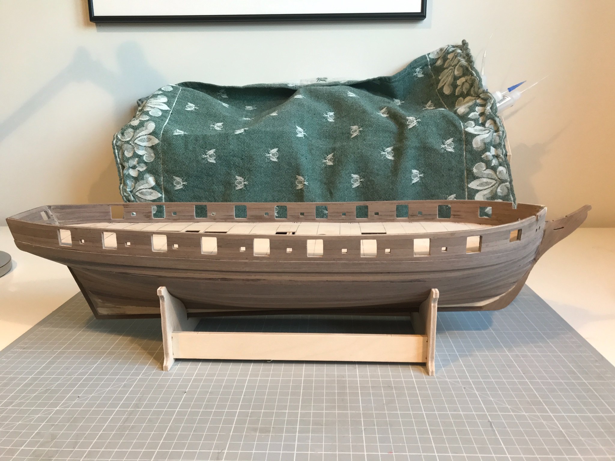
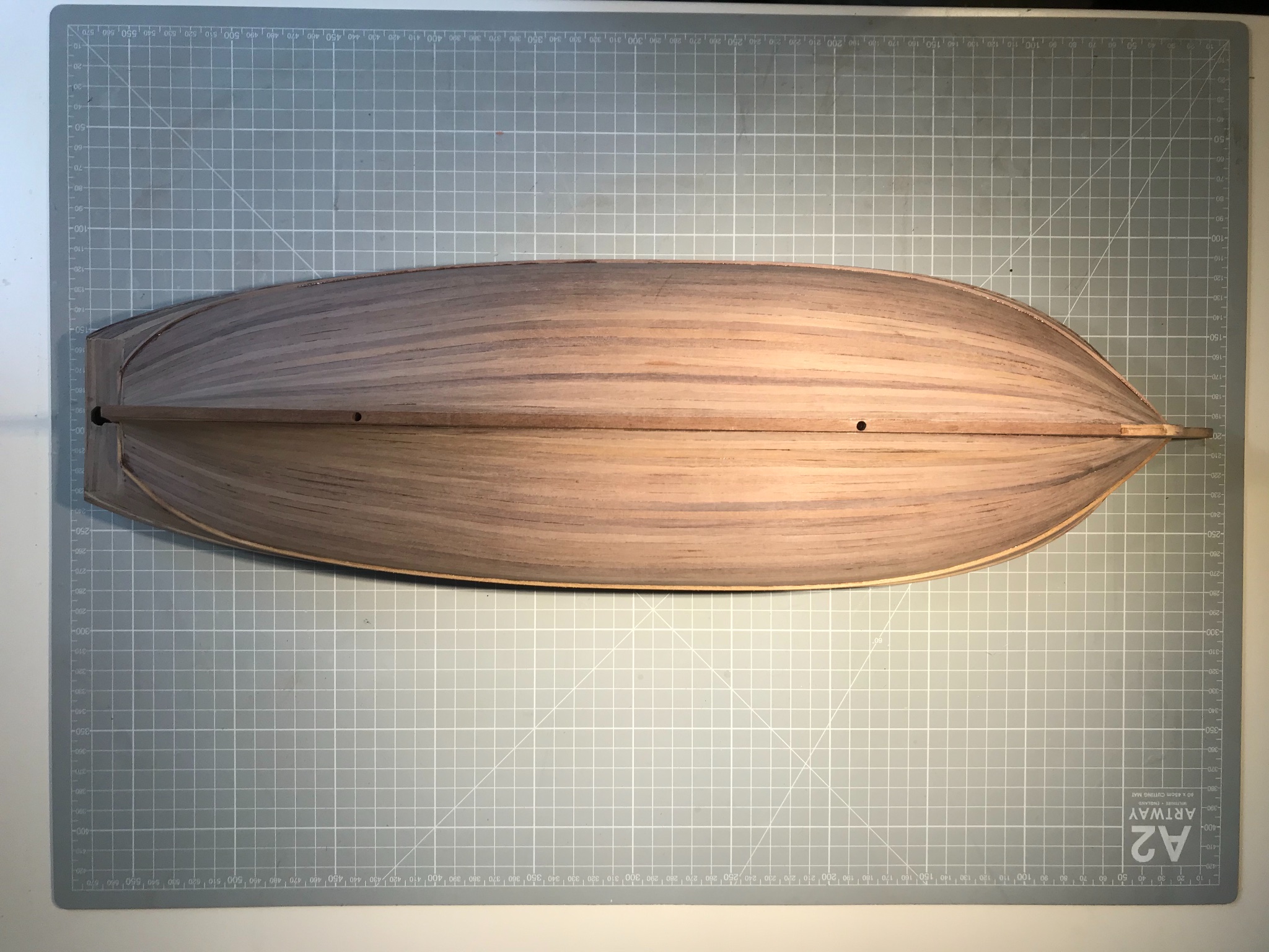
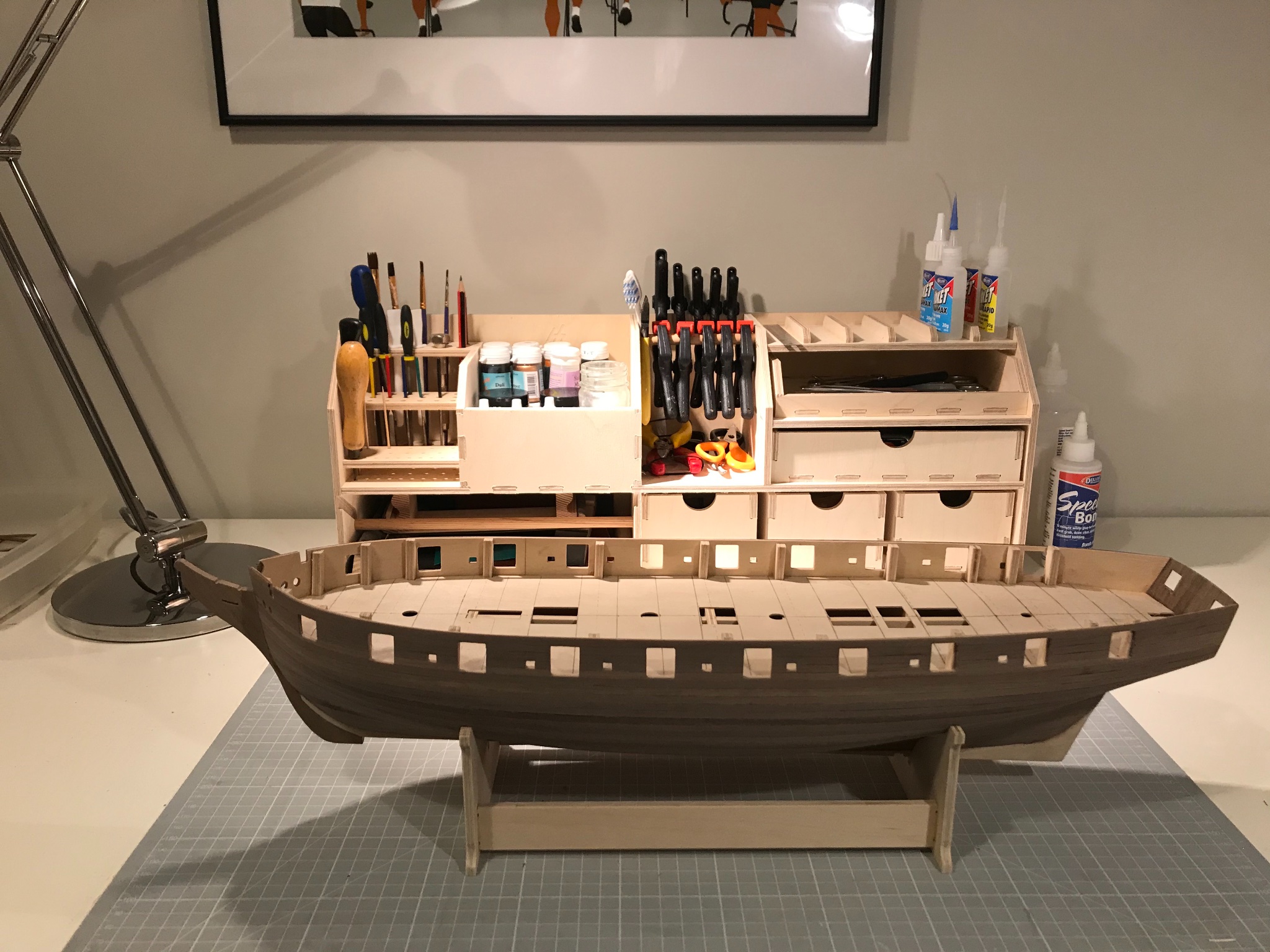
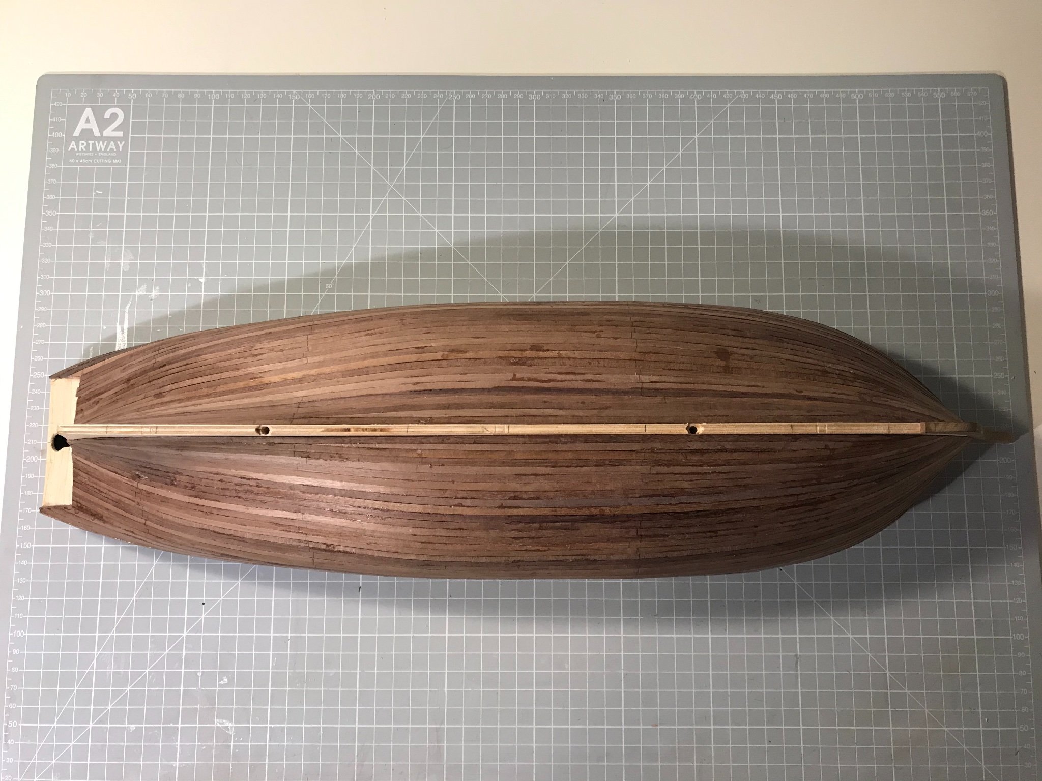
So, been planking. This shows the results with no sanding yet. I spiled with some care down to the waterline, and set a sheer line using a thin thread of masking tape. I had planned to stop there and just slap them on, but thought this a good opportunity to improve my skills so carried on. I really should have put in another line at around the belly of the hold - but, well, I'm going to copper them, so thought I'd just use the one plank geometry and as a consequence the line of the planks is not quite as graceful as I would like . I inserted a couple of stealers, and I think it came out neat enough.
I didn't plank the stern first, as I want to add the stern post and the keel after I have sanded - though I think it would look better to have the side planks ( there must be a technical term for those) overlapping the stern planks. The Cruizer brig model in the NMM (photographs above) has a neat solution, but I'm not sure that I could execute it accurately enough. We'll see.
I do regret not cutting a rabbet at the prow (or should I say stem?) since gluing the planks there was challenging - sanded, filled and painted or coppered probably means it does not matter. I am pleased I did not cut a rabbet along the line of the keel or seek to plank the deadwood on the false keel as once sanded I think the lines will be smooth and pleasing to the eye.
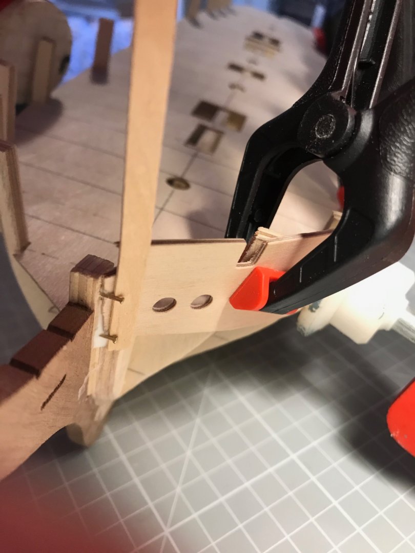
The two holes showing on the false keel and the hex cutout s around them are for a pair of M3.5 machine screws that will attach a pair of brass columns once the hull and deck are done. A pair of hex nuts will sit in the holes and be held captive between the keel and the false keel. It was fun getting the spacing on the holes right (genuinely; and if you didn't enjoy that kind of fiddling around, model ship building would be a challenge) to give the keel the correct dip, and drilling the holes at the correct angle, was similar fun. The only unknown is by how much the thickness of the second planking has changed the overall "elevation" of the keel on the columns since the planks are at different angles at the two hole. I won't know the answer until I've sanded.
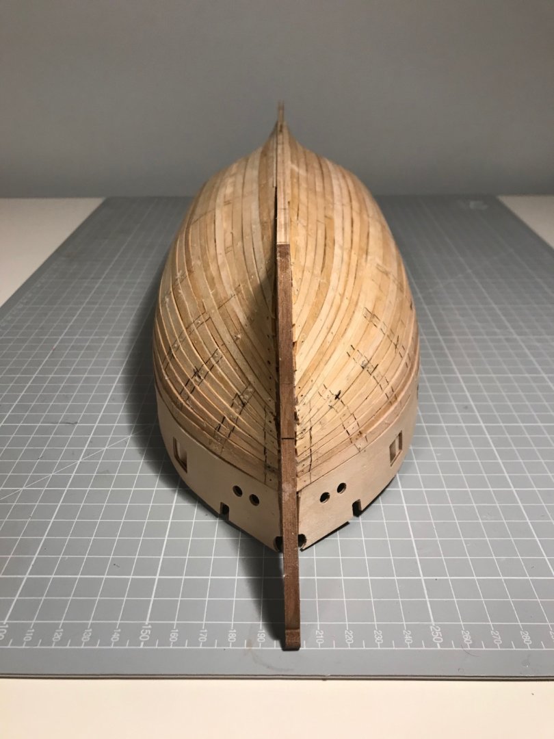
I think the sequence from here is cut out the gun and sweep ports (possibly cutting our a couple of frames where they get in the way) . Sand the planking completed so far. Fix the keel and sternpost. Plank the stern. Sand some more.

- chris watton, Liam, CiscoH and 3 others
-
6
-
Quite remarkable rigging and photography, Jason.
-
On 11/19/2020 at 3:31 AM, jwvolz said:
Nice work so far Mike. Having built a Cruizer, I can agree it does take some work, and the instructions are rather light, but luckily the plans are pretty good. I modified a ton of things on mine to try to get more historically correct.
If you can find a copy the book Modelling the Brig of War "Irene" by E.W. Petrejus was an invaluable resource to me during the build.
Joe, I suspect your advice to track down Petrejus's book could be the best piece of advice I get in this whole build! Copies are few and far between in the UK- expensive and usually missing the large plans. There was one on ebay - at half the price of most suppliers. So I bought it half expecting it to be any or all of: in Dutch, falling apart and missing pages and plans. It arrived yesterday in close to pristine condition, all pages and plans intact. And, to my relief, in English. Not only is it entertainingly written and illustrated, it is a fount of detail. I am now much more relaxed about doing the rigging - though that is some time away at the moment.
-
6 hours ago, jim_smits said:
Hi
The mounting posts are these:
I used one of these and another shorter one. Both at Cornwall Model Boats.
Hope that helps.
Thanks. Sadly, I think AL have gone bust, certainly no-one seems to stock their stuff at the moment. I think I can adapt what I’ve got, or alternatively I’ll get some time on a lathe at work and make my own, and then either learn how to use a modern milling machine or ask a friendly tech to mill a slot in the top
-
19 hours ago, jwvolz said:
Nice work so far Mike. Having built a Cruizer, I can agree it does take some work, and the instructions are rather light, but luckily the plans are pretty good. I modified a ton of things on mine to try to get more historically correct.
If you can find a copy the book Modelling the Brig of War "Irene" by E.W. Petrejus was an invaluable resource to me during the build.
Thanks Joe. Your Sophie looks a treat. I tell myself not to obsess about correctness - after all there were so many of this class, there is no correct. And really correct is 64 times bigger. However, every time I see something that wouldn’t work in a model it winds me up. I will be searching for “Irene” straight after hitting return!
-
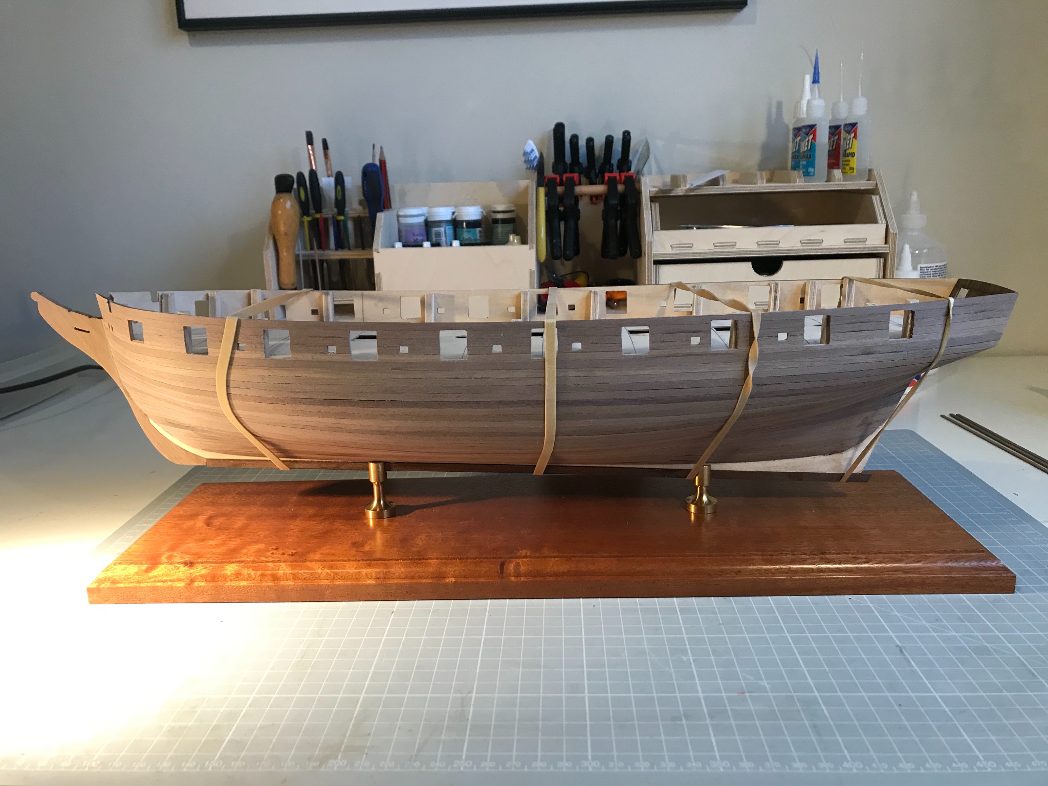
I'm happy with the planking. Could have done better in a few places, but sanding and a fairly modest mount of filler should fix that. Decided to plank the stern counter as the simplest way of closing up with the hull planking. It also means I can repair a flaw in the curvature of the counter. Apart from trimming the planks at the stern to get at the counter, and the counter itself, I've not sanded anything yet. I have not fully planked the false keel as an alternative to rebating the planks. I'll see how that goes. I soaked the planks and was surprised to see how much they swelled, and then shrank on drying.
Thinking that I might pin the second planking (Horror!) as it will all be painted or be beneath the copper - would welcome views on that.

- Beef Wellington, BenD and p.hoek
-
3
-
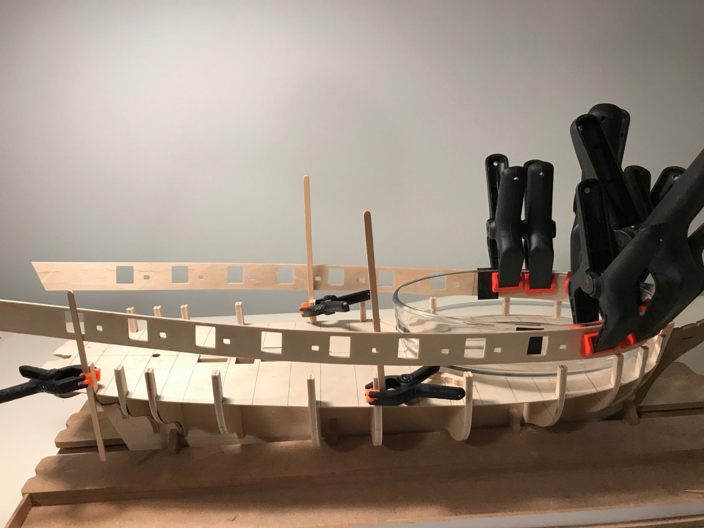
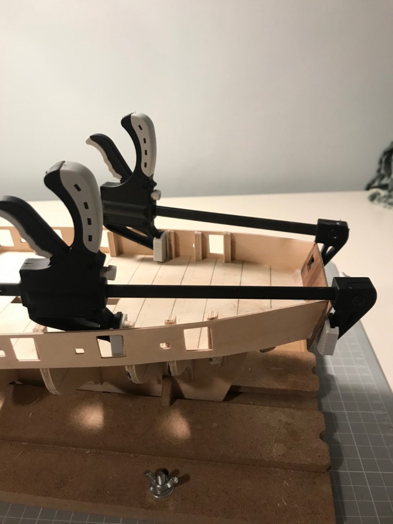
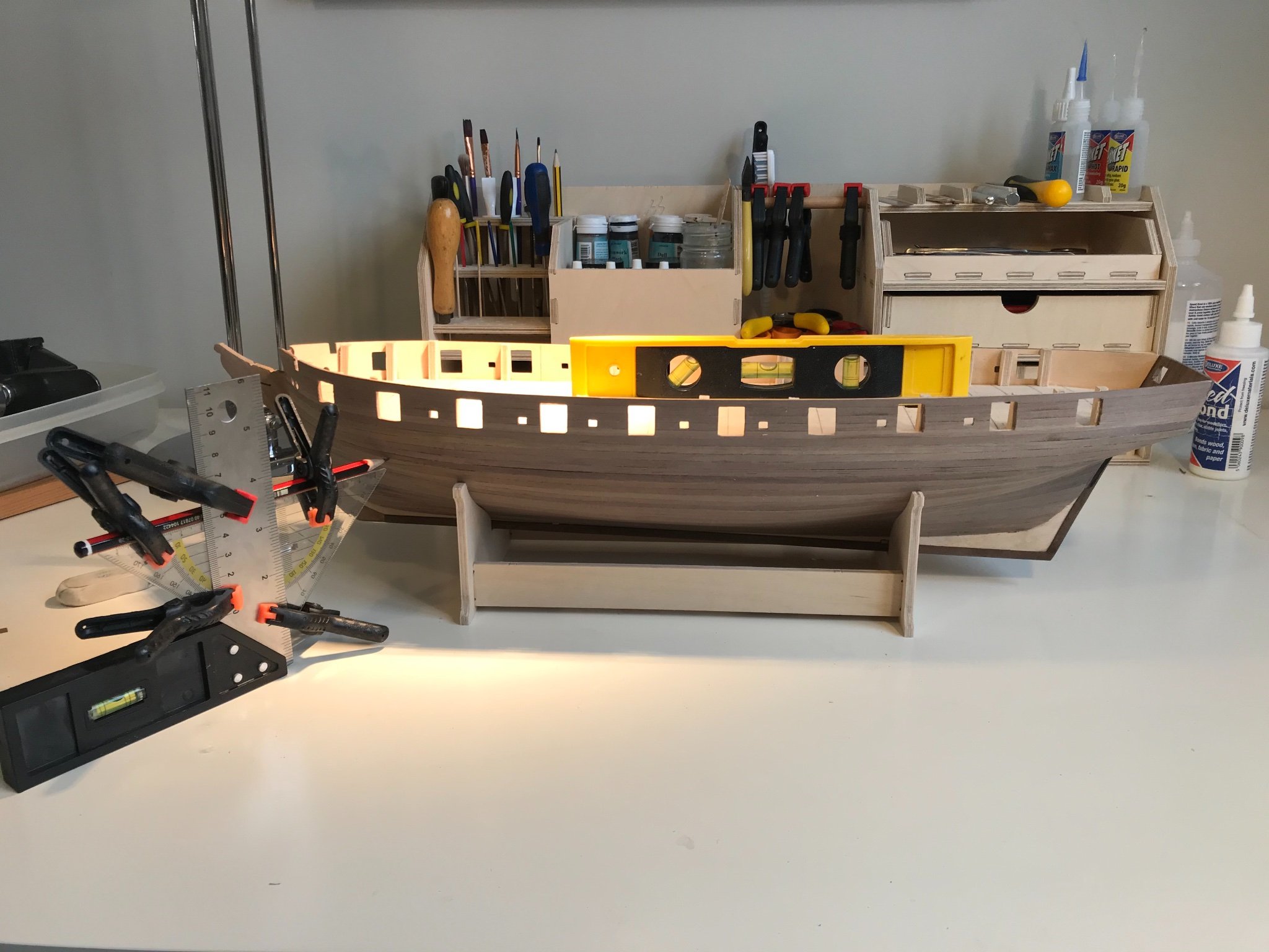
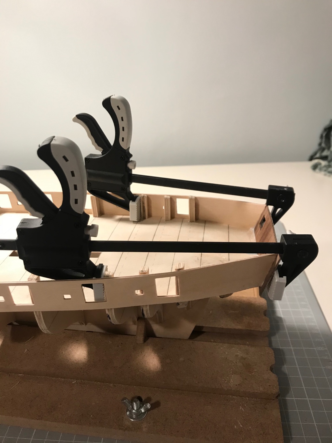
Fair bit of progress in the last few weeks. Bulwarks fitted and first planking done. I soaked the bulwarks for a couple of hours and then formed the round a conveniently shaped bowl. Clamped and glued them without too much difficulty. Was obsessively concerned with making sure the ply of the bulwarks extended down to the deck ply so that it could bond to it, since at this stage it's hard to believe that once the bulkhead extensions are snapped off that there would be much attaching the bulwarks. For this reason I didn't pin them since the tumble-home curvature would have pulled them away from the deck (I worried). Actually once it's glued on it feels very solid, and once the first planking is done, it's hard to see why I was worried. If I did it again, I'd pin to allow easier positioning.

-
On 11/16/2020 at 5:39 PM, jim_smits said:
Hello there!
I haven’t been on in quite some time! You’ve picked a great model as a novice. Snake was my first build started.
You are correct that I haven’t yet finished but don’t let it worry you, life simply got in the way. I moved to a new house and didn’t have a work area set aside and then my son was born a little over two years ago so finding model time has been very hard!
Any questions just ask and I’ll try to help. Noticed Beef has commented as well and he is an excellent modeller.
All the best!
Jim
Hi Jim. Just had a look at your log, and your Snake looks a beaut. And there is a nice symmetry to me starting and you slowing - our youngest has left home and now I have her room as my work area.
And since you offer, I have a question. Your Snake is mounted on a display board by brass columns. These all look remarkably similar to the Amati products that I have just bought from CMB - I plan to install a pair of captive nuts under the keel (which might have been your idea, I certainly saw in somewhere on this site). An issue with the Amati columns is that those of differing heights are also of differing diameters. Did you use Amati's and did you use the differing sizes? Do they look OK. Or did you find another source?
-
Your rigging is a sight to behold, Jason. Well the whole build is, really. Keep posting so we can watch an learn
- mort stoll and Martin W
-
2


Chris Watton and Vanguard Models news and updates
in Traders, Dealers, Buying or Selling anything? - Discuss New Products and Ship Model Goodies here as well!!
Posted
Hi Chris. Hope things are going OK with you, the business and Sphinx. I had got used the breakneck progress you were making, and miss the frequent updates. I'll try to be patient (and concentrate on the build in hand).
Mike