


Mike_H
-
Posts
225 -
Joined
-
Last visited
Content Type
Profiles
Forums
Gallery
Events
Posts posted by Mike_H
-
-
Seems I've not been on here for a while. That's mainly because I retired from work a month ago, but the Admiral only retired this week. That gave me a month to get back on my bike and do some ship building, but not much appetite to sit at a computer and update this build log.
So here's the update - all five components of the masts are built, painted and installed, and all the lower deadeyes are in place. I found the deadeyes quite frustrating as the metal loops they sit in were tricky to handle - opening them out to insert the deadeye always distorted them, so closing them back up again usually messed up the little loop in which the chain sits. I closed up the channels using some epoxy putty, which not only makes things seems stronger, it hides the mangled metalwork. Anyway, I got there in the end. Making the masts was reasonably straightforward with the usual mix of patience and tolerance of imperfections.
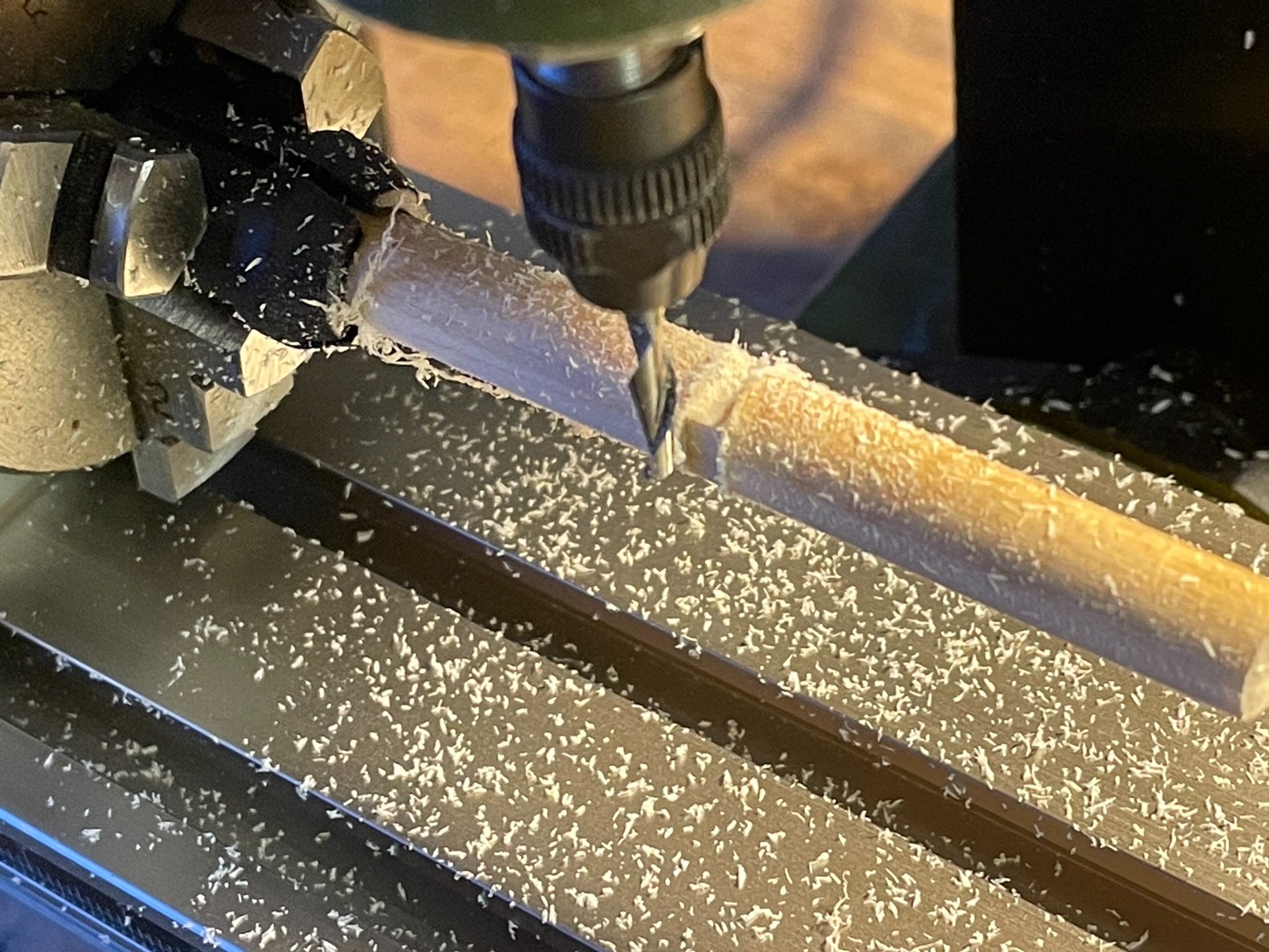
Very glad I bought the Proxxon mill and lathe. The mill makes machining the square sections of the masts very easy and I even made the heels of the upper masts octagonal. That was a little tricky with 4 mm dowel, but once I bodged up a tailstock from the lathe to use on the mill, it worked ok


Bowsprit next then perhaps some shrouds, and then the spars. Or maybe a mix of the two.
- BenD, AJohnson, GrandpaPhil and 2 others
-
 5
5
-
18 hours ago, chris watton said:
OK, all Sphinx kits are now gone until next month, of which I am working on now, laser cutting. Hats off to my wife, Chantelle, who managed to pack up 51 kits from Friday to Sunday - damn that was a lot of foam and bubble wrap!
That's excellent! It means I cannot distract myself from Snake by buying Sphinx, and must wait for a little time, during which Chris's plans for the future will doubtless grow. More importantly, it means that Chris's decision to go full time is vindicated and we can confidently expect Vanguard to go from strength to strength
- Richard44, Nipper, Dale Hallier and 9 others
-
12
-
Lovely to see such refined patient progress. Keep it up, Jason.
Mike
-
4 hours ago, chris watton said:
Next big one - Phoebe (36), Indefatigable (need I say more..) or Bristol?
Well any, or all? My heart shouts Indy - for her exploits under Pellew, for exemplifying the Royal Navy in the French and Napoleonic wars, for being the first ship of that period who’s name I knew (courtesy of CS Forester, when I was 12), but most of all for her muscular proportions and looks. My head says - where the hell would you put it, she’s huge? Heart wins this one. But heart also loves the detail of Sphinx, and Chris seemed to have doubts about doing that level of detail on a larger ship. But perhaps, seeing how Sphinxes have flown our the virtual pre-order door, doubts have also flown.
-
All that remains is to add the iron bands:
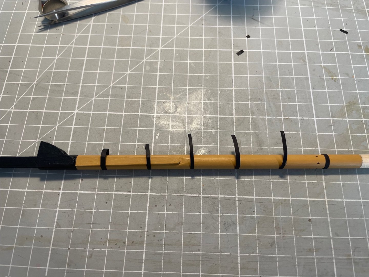
reasonably straightforward using a method I saw elsewhere on this site - perhaps @James H - 2mm wide lengths of cartridge paper cut out. Tacked in place at 25 mm intervals on the after centreline of the mast using CA, wrapped around, trimmed to length, coated lightly with PVA, pressed on and held for 2 min. Scarcely a worry. Top tacked with PVA, seemed to sit square and parallel to the waterline (much shaping of the bibbs required at an earlier stage)
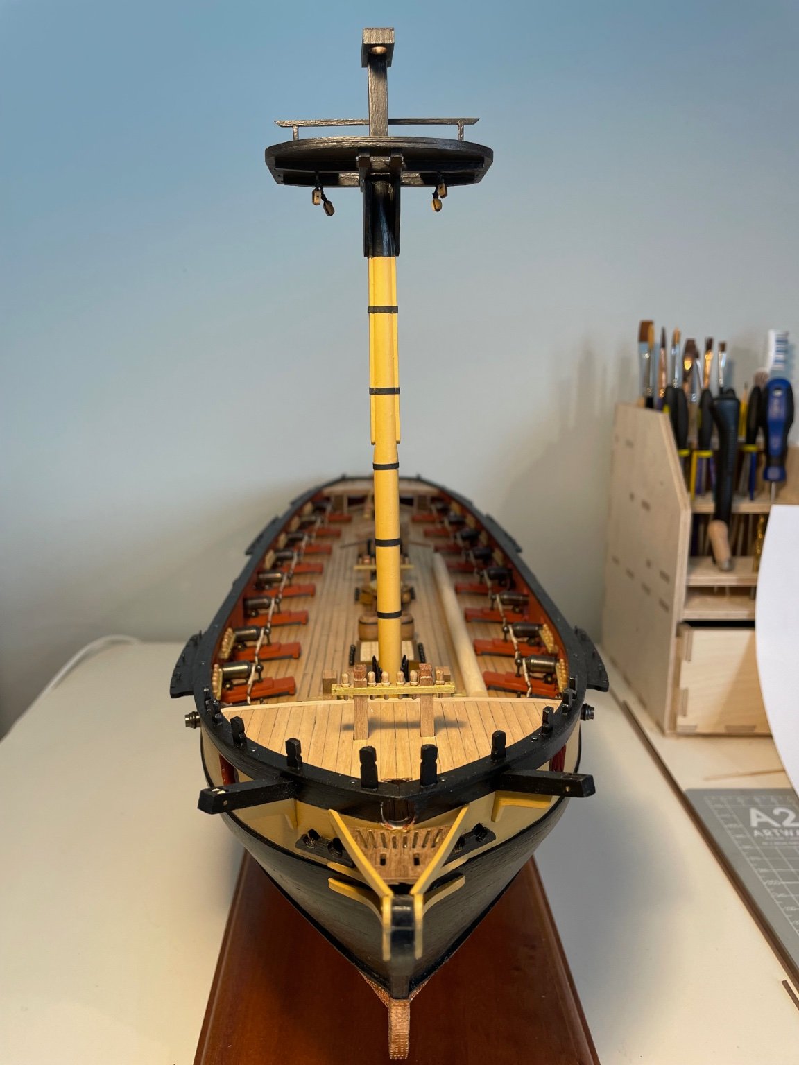
Foremast swayed up!
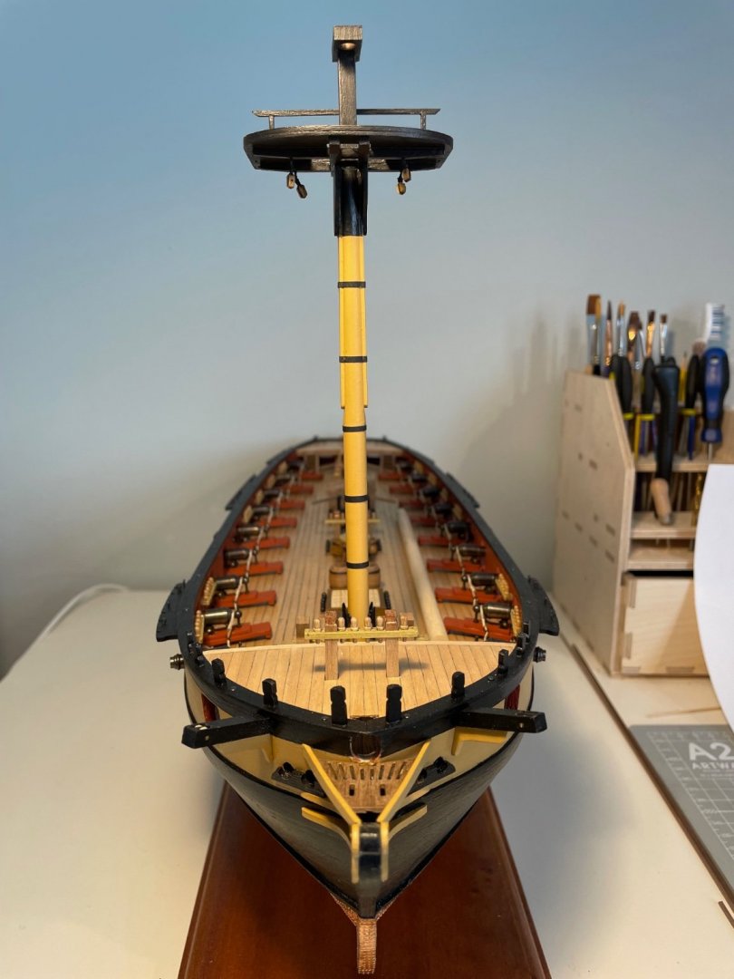
You can tell, I insist, that the mast has been tapered to take the cheeks
And herre that the top sits on the bibbs

You can even get vertigo

Back when I have done another one or two.
- Beef Wellington, BenD, AJohnson and 1 other
-
4
-
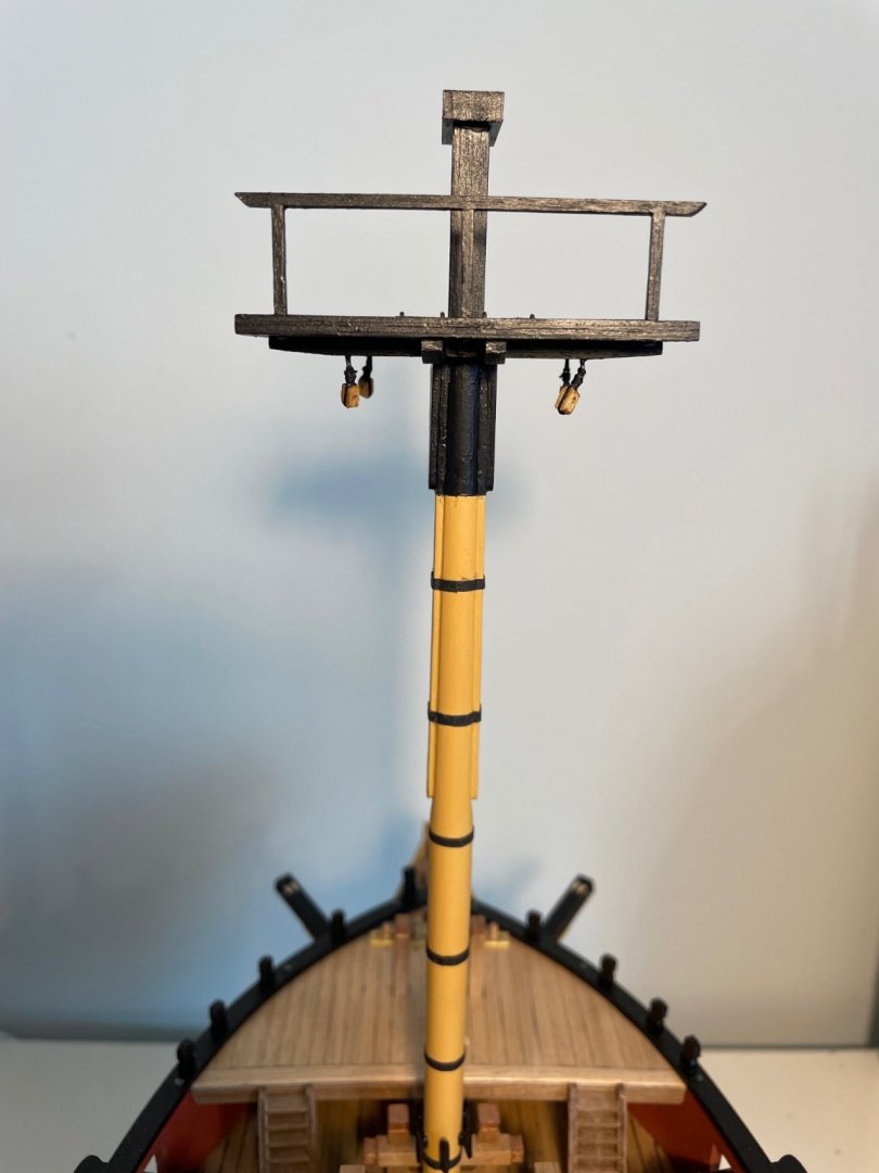
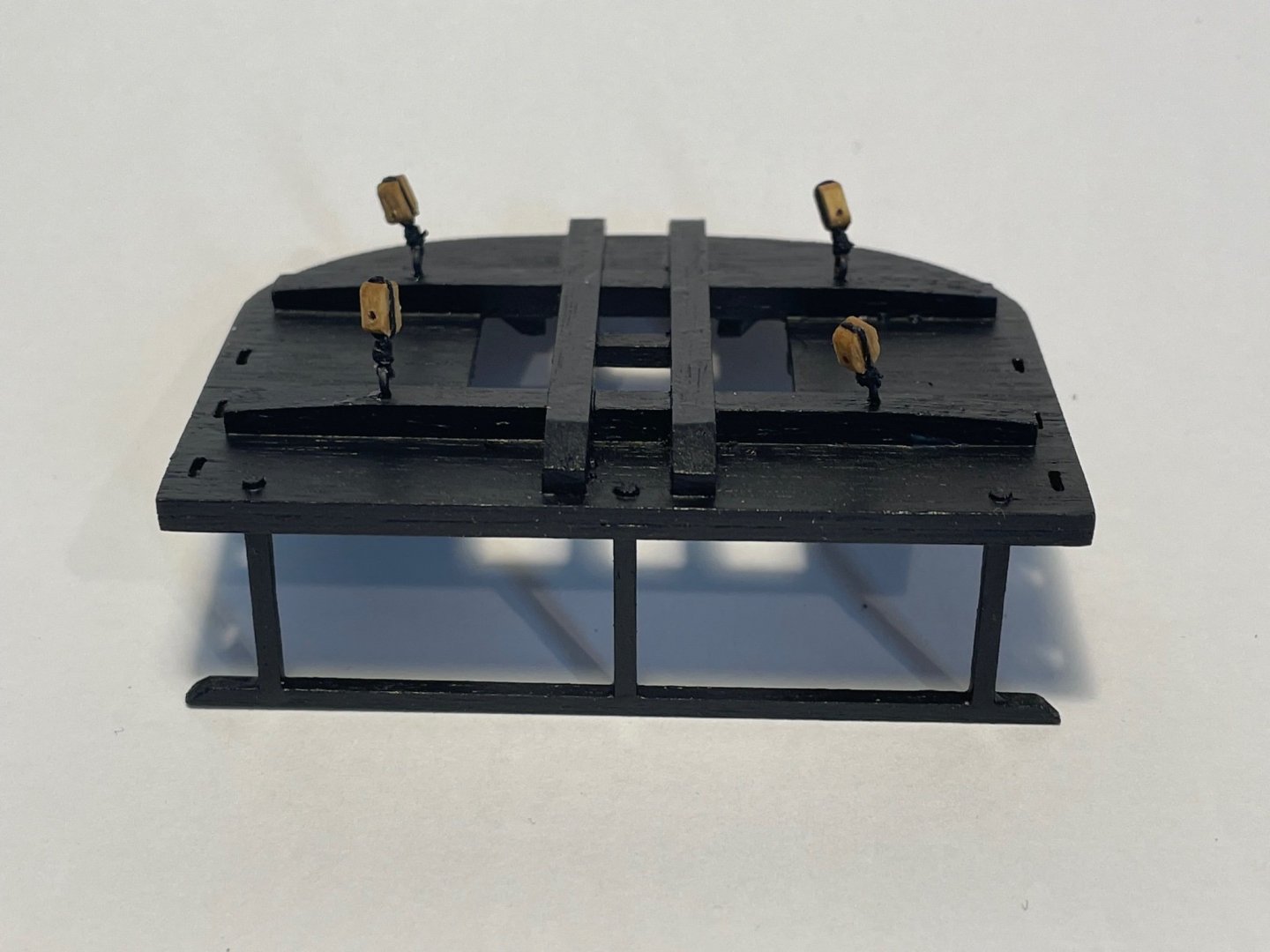
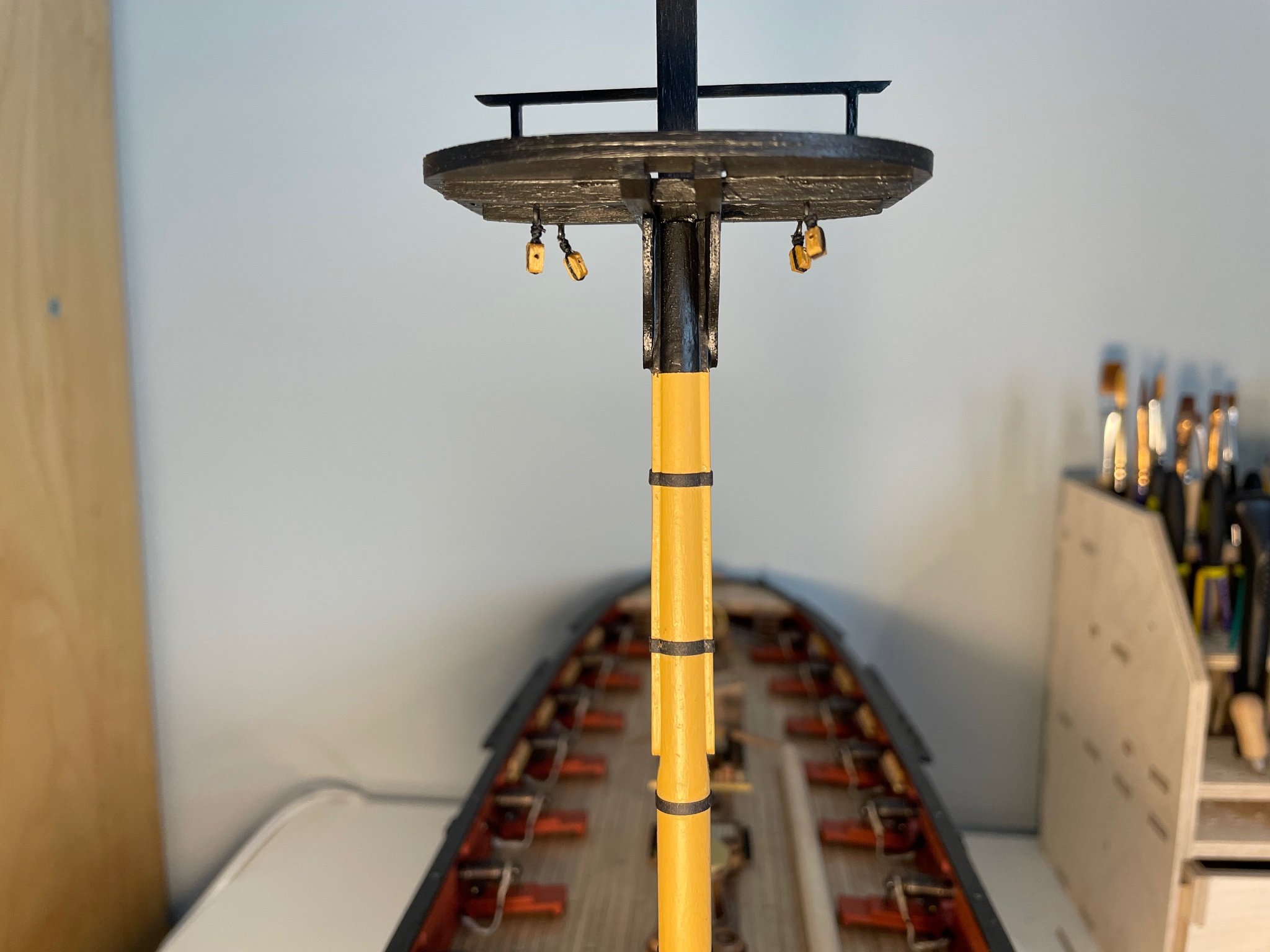
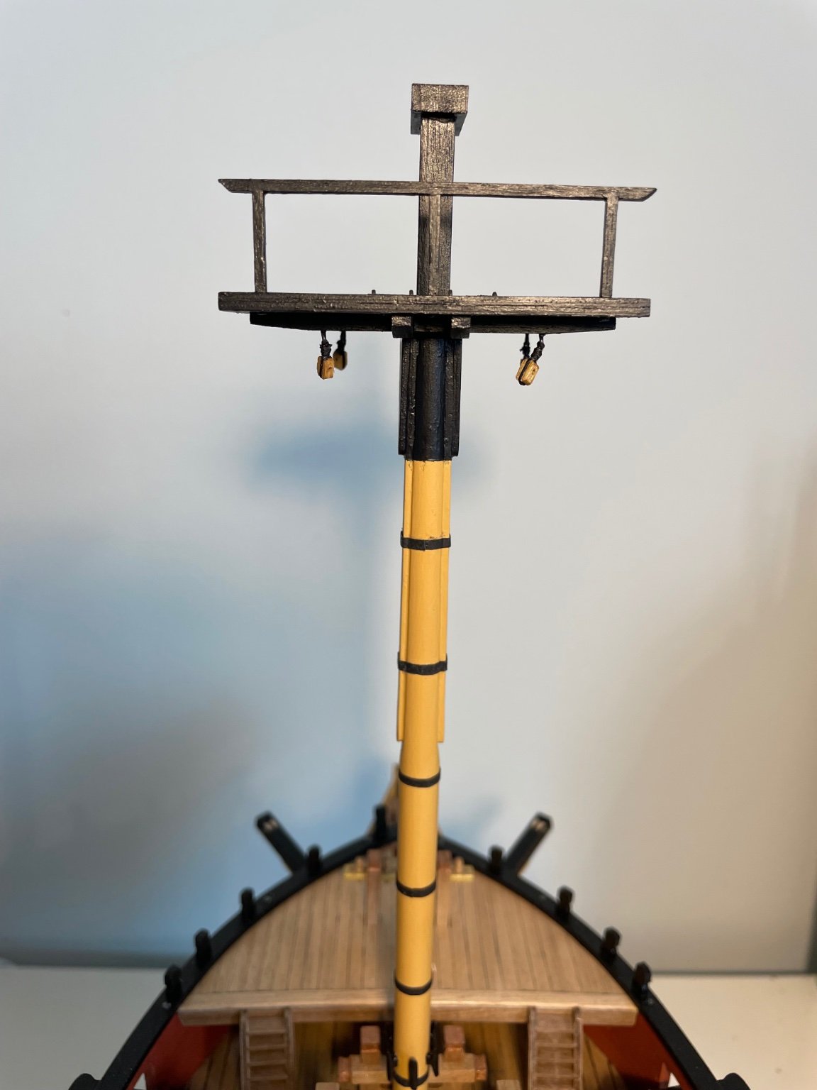
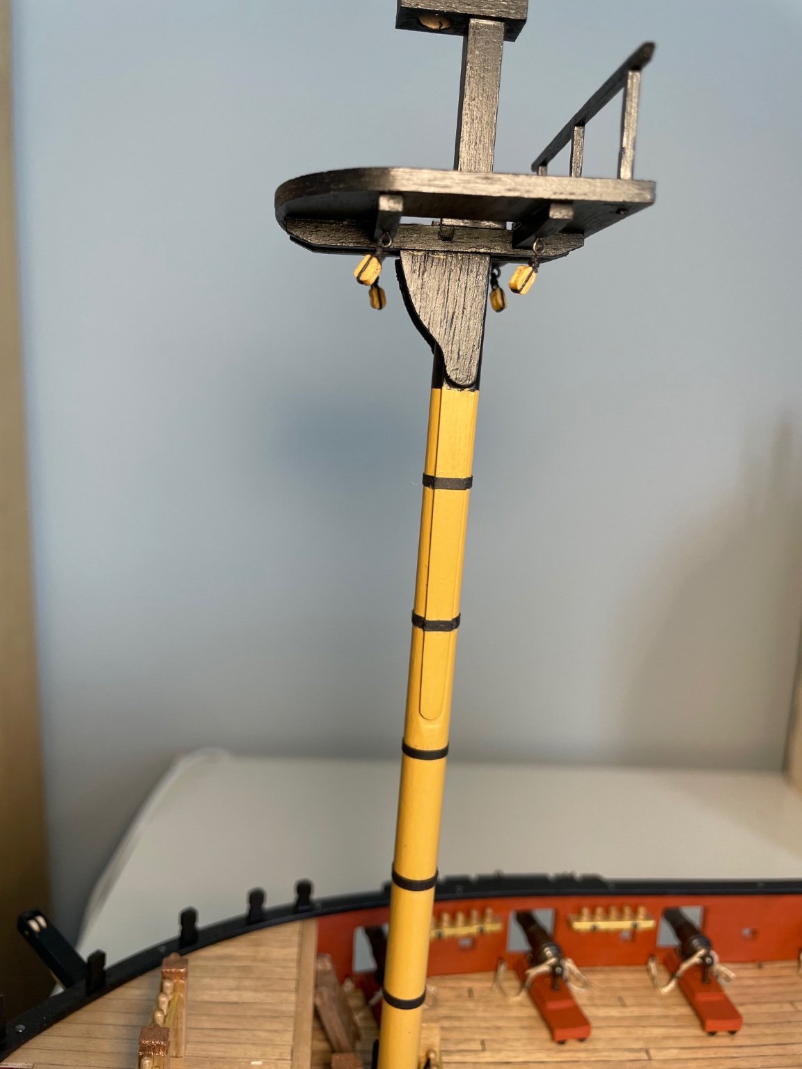
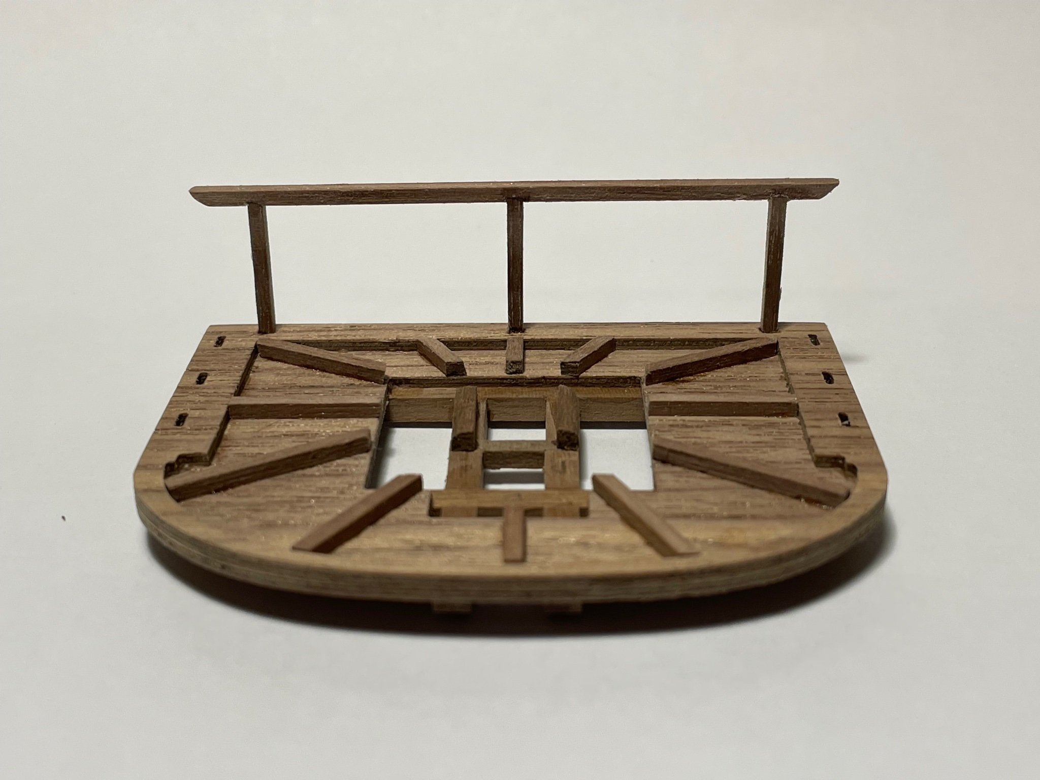
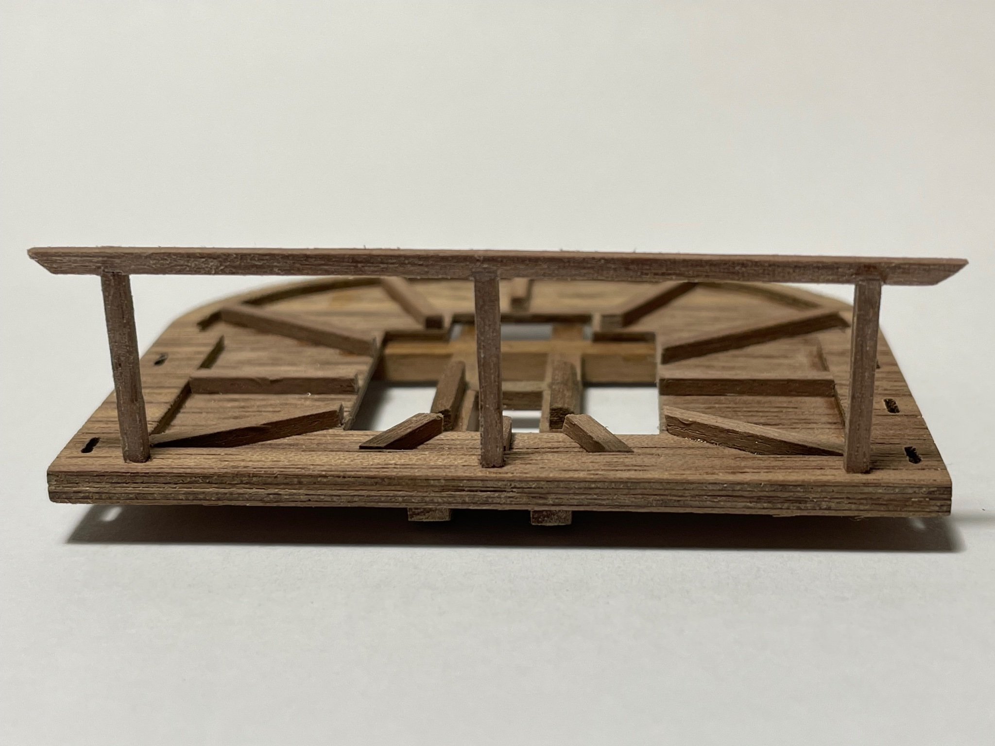
Fore Top
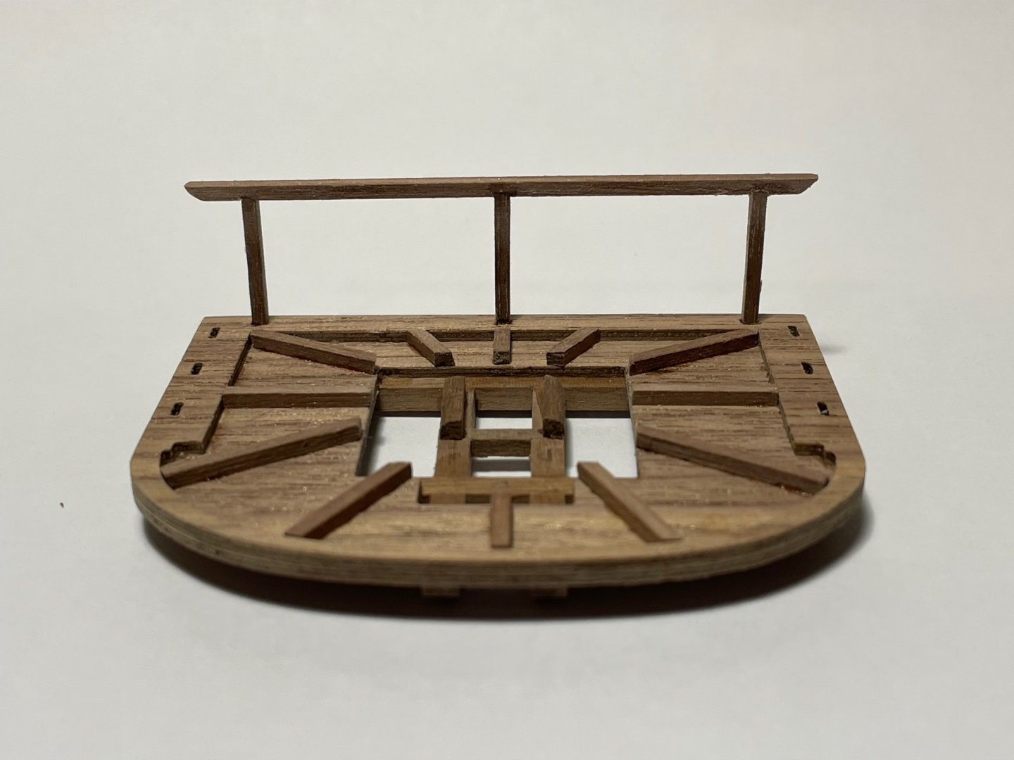
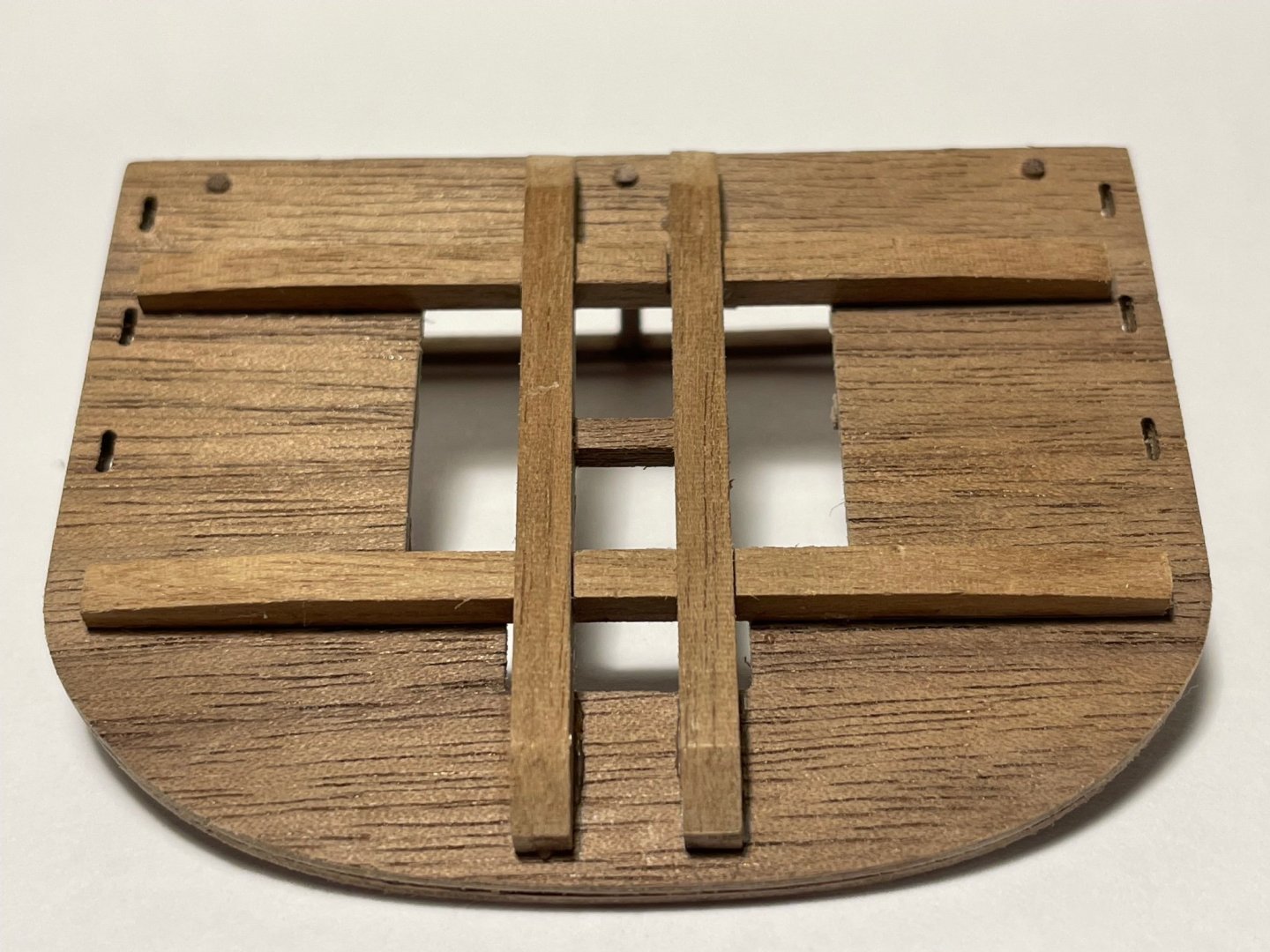
Quite a lot of fun to build, but surprisingly labour intensive. The Trestle- and Cross-trees should slot together but the slots need to be machined out.
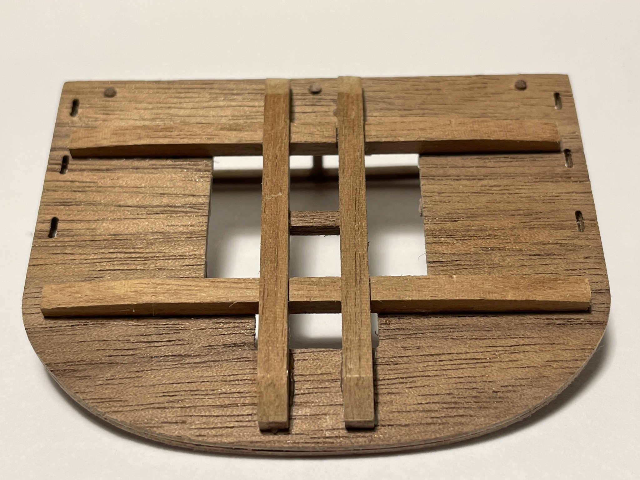
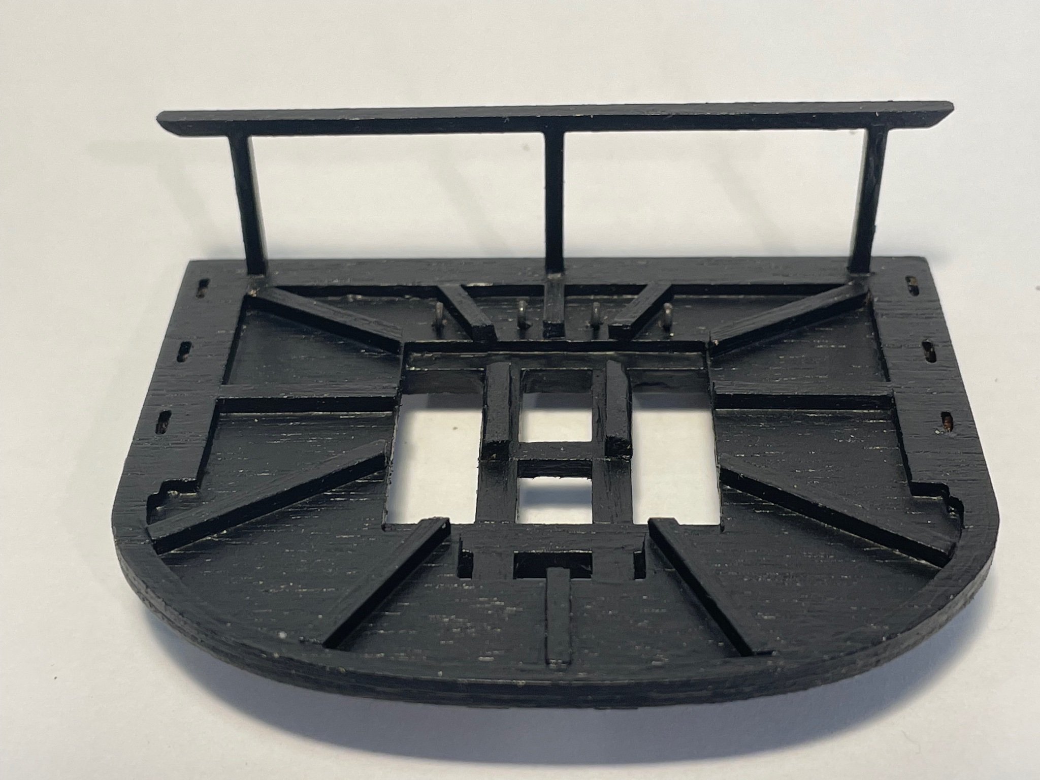
Two pieces of original thought required. I laid out the battens at 30º intervals radially around the centre of the mast - I'm not sure what the real-life arrangement was. To erect the rail along the after-edge I cut the supports 3 mm over-length, and then turned the bottom 3 mm to a 1.5 mm diamter, having drilled 1.5 mm holes along the after-edge of the top (you can see the circular supports on the underside). The supports then slotted-in as round pegs into a round hole. The rail itself I then marked up and milled 0.3 mm deep slots to take the tops of the supports. In the photographs you can just see the rebates to take the supports. Once glued it seemed remarkably strong

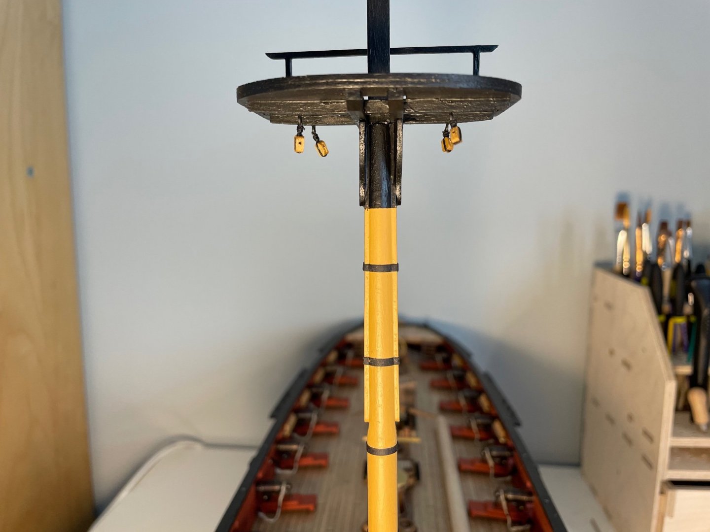
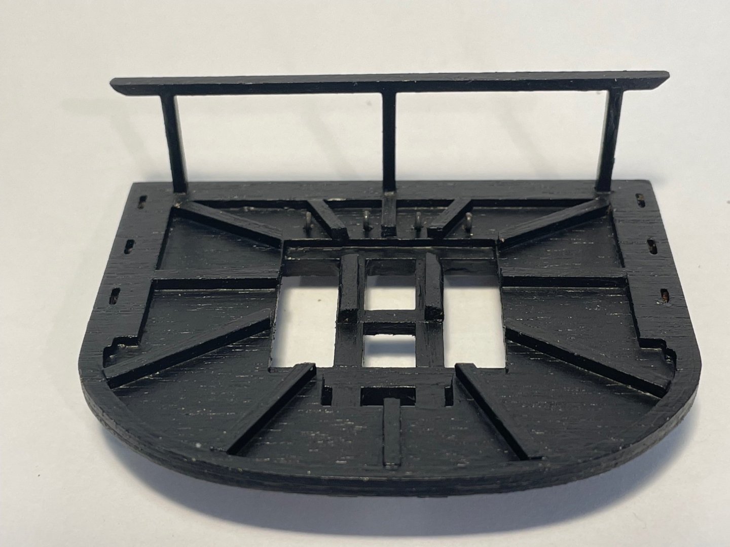
And here it is painted and with the ringbolts and blocks installed.
- BenD and GrandpaPhil
-
2
-
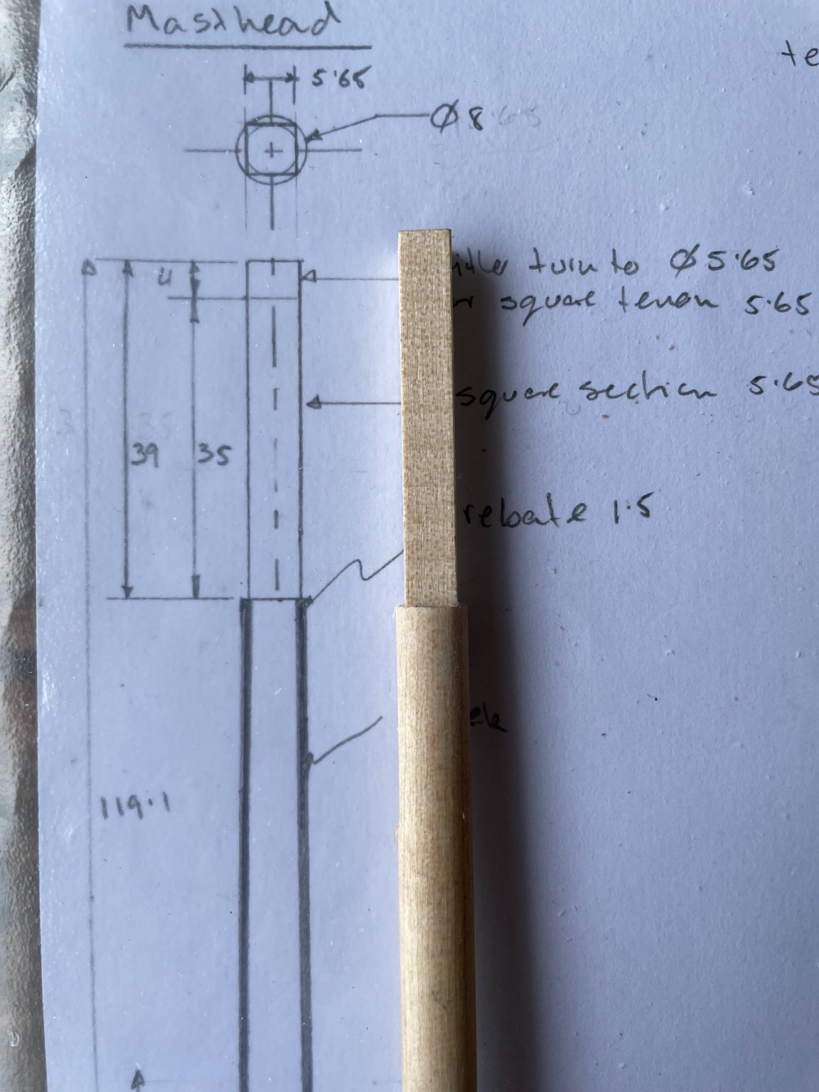
The sun has been out so I've been indulging one of my other obsessions - riding a bike around the Peak District. I've also combined my engineering obsession with model ship building and bought a Proxxon MF 70 mill so I don't have to battle with filing flats, among other things. I decide to really go engineer and draw up what I needed to do:
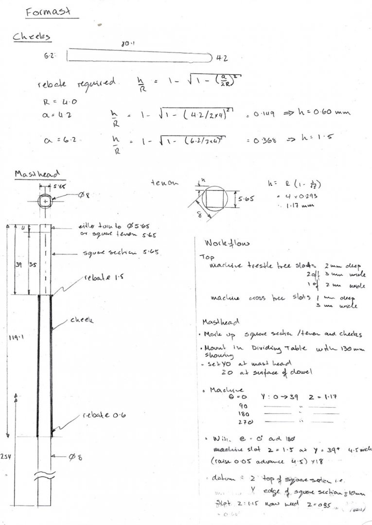
According to Petrejus, the cheeks are closer together at the top of the mast, so the amount of material to be removed, or rebated, increases the higher you go. That means that the shape of the "flat" to which the cheeks are attached is not rectangular, and so, of course, nor are the cheeks. Those provided with he tkit vary from 4.2 to 6.2 mm. Using the equation at the top of the sheet, to make a flat of width a, machine down a depth h (where R is the radius of the material). that means that at the top of the cheek, the rebate is 1.5 mm and at the bottom 0.6 mm.
But before that the square tenon at the top must be machined, by reabating 1.17 mm
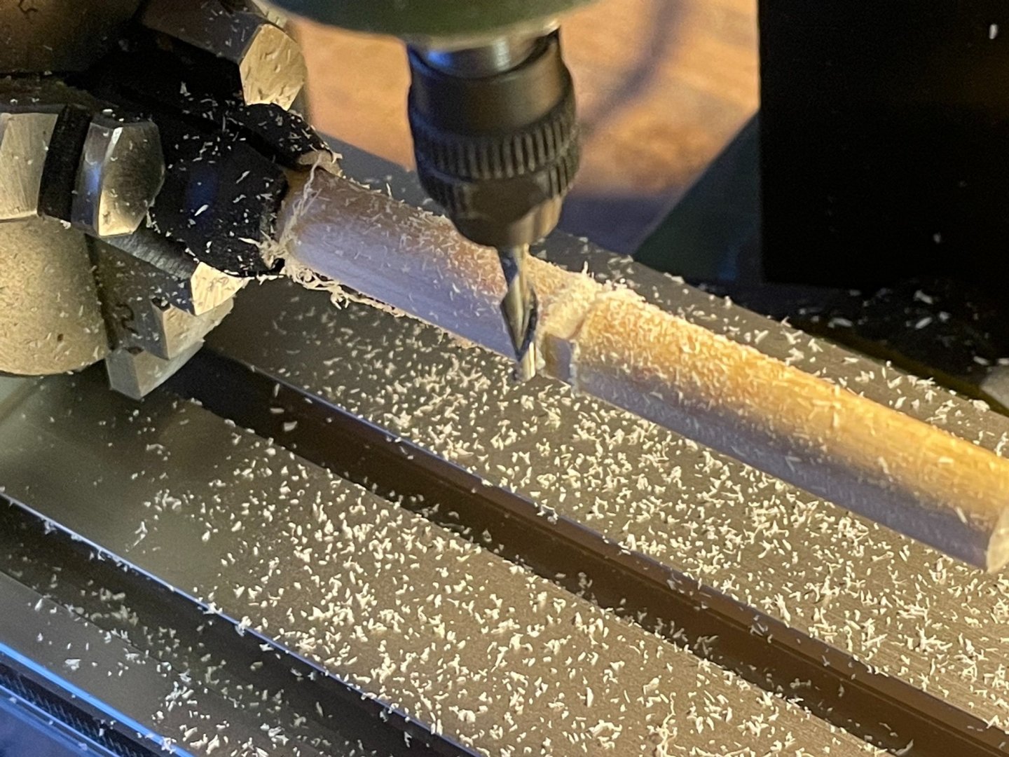
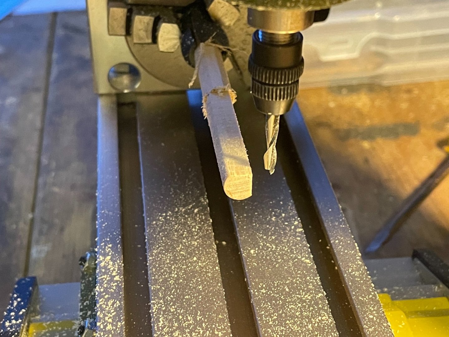

Machining the cheek flats was a challenge for the first use of the machine, but here's the rough finish
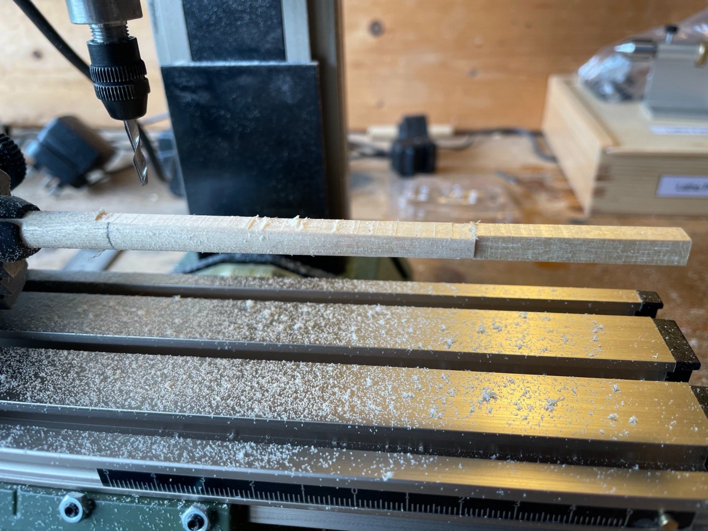
Once sanded it looks just fine. A bit of cartridge-paper work to do, and then I can show the finished product.
- GrandpaPhil, AJohnson, DaveBaxt and 2 others
-
5
-
Lovely to behold, James. As Chris says, you really are doing the magnificent kit justice. (Aright, he didn't say magnificent, I did!)
- Bettina, KentM, chris watton and 1 other
-
4
-
Very nice, Ben. I particularly like the ironwork on the companionway and you obviously have something grand planned for the rigging of the guns. To say nothing of the rigging thread. Is it possible, do you think to make parcelled rigging for sale? If so, there would be quite a market even at astronomical prices. Just a thought.
-
21 hours ago, Beef Wellington said:
Hopefully this photo makes the jig operation clearer
Ah... it does. Delightfully, it's the inverse of your jig for shaping your hatch-comings on Snake.
I'm currently sitting in a Zoom meeting, which gives me enough time to go full-engineer on planning out my next stage of my Snake, so if it goes to plan, I'll post calculations, sketches, workflow and final result. Fingers crossed.
I must say that your advice philosophy of "thinking ahead and not sweating the small stuff 🙂", is just what I strive for. The paradox is that thinking ahead is all about sweating the apparently small stuff!
- egkb and Beef Wellington
-
2
-
11 hours ago, Beef Wellington said:
@Mike - very much enjoying watching your Snake come together
That's kind of you. By coincidence I have just spent an hour reading through pages 12-15 of your Snake log to see how you dealt with masts and bowsprit - particularly in connection with shaping. Very enlightening. Think I'm about to explore the wold of serving
On the design of your planking jig, two things occurred to me: are you an engineer by any chance? (I am, and am in awe) The spreadsheets and jig-making say yes. But delaying to now to get a digital calliper says no (I expect I'll buy another as I need one in the shipyard (spare bedroom) and the spar factory (garage - think UK, 8 ft wide, no possibility of a car in there).
And then the second point, how does the jig work for guiding the sanding? Asking our of interest because I cannot imagine having the craft skills for this (and besides I could spend more money and attach CNC control to my Proxxon mill)
-
Crisp as ever, and celebrating each little gain. Together these make an object lesson. Only just remembered to follow this, so now look forward to more canapé-sized bites of (near) perfection.
-
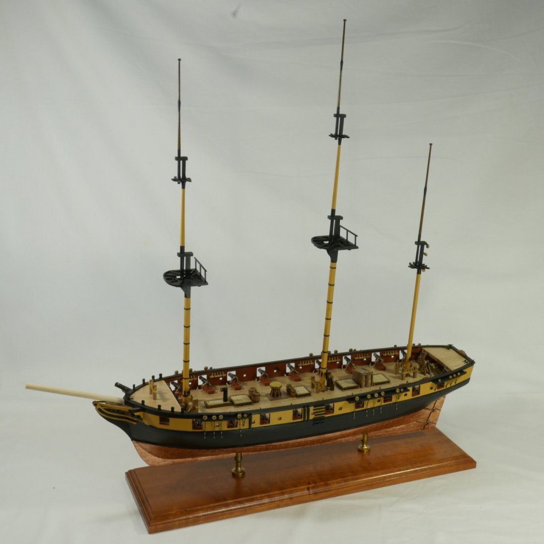
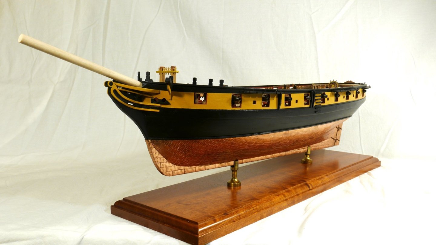
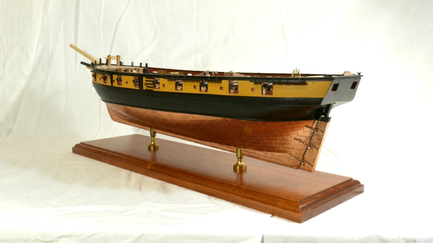
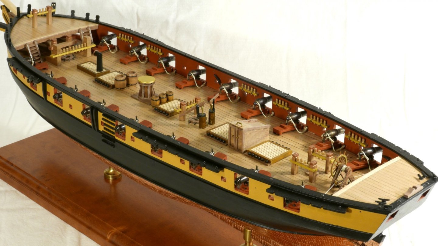
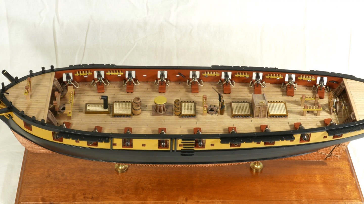
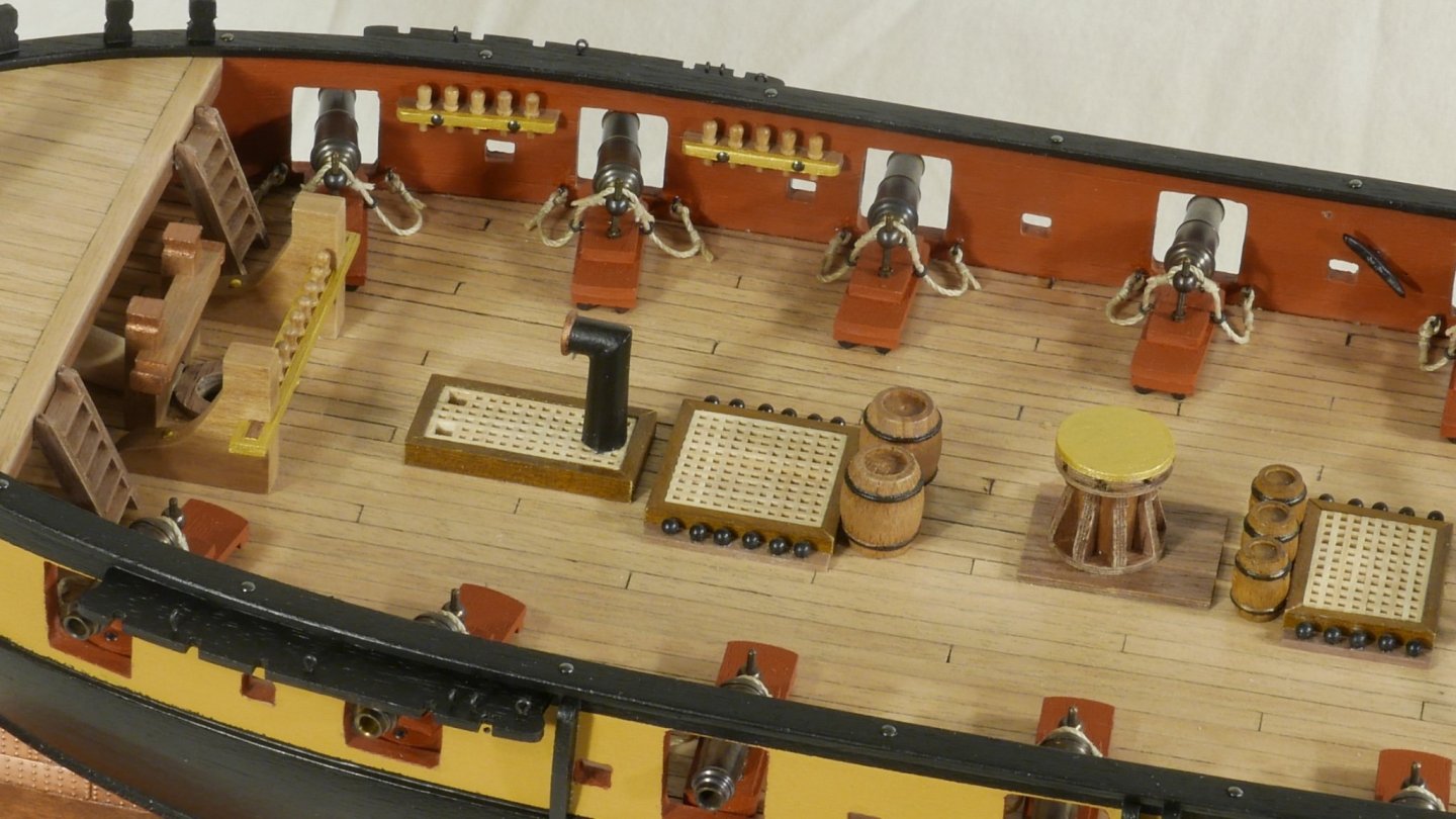
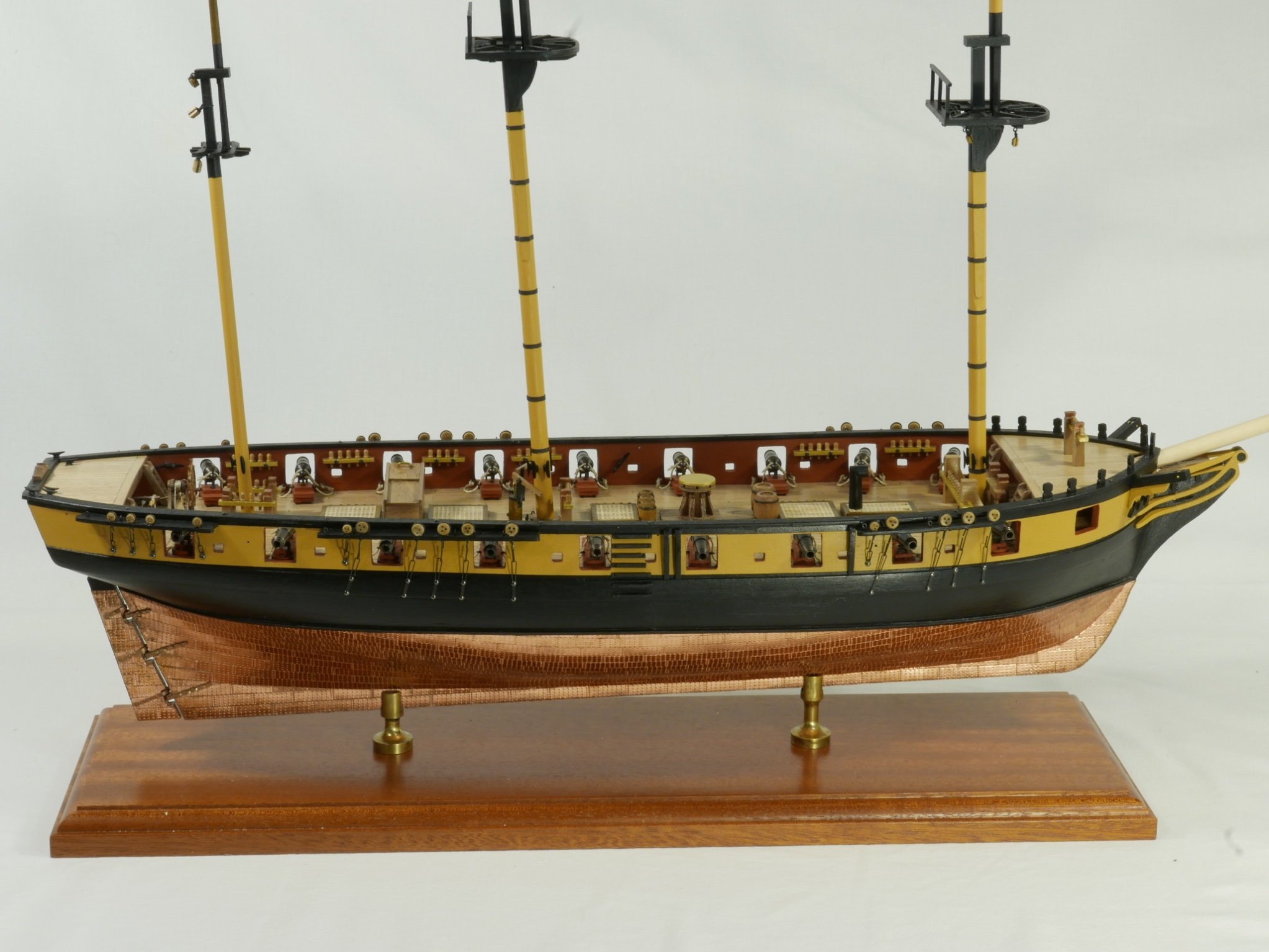
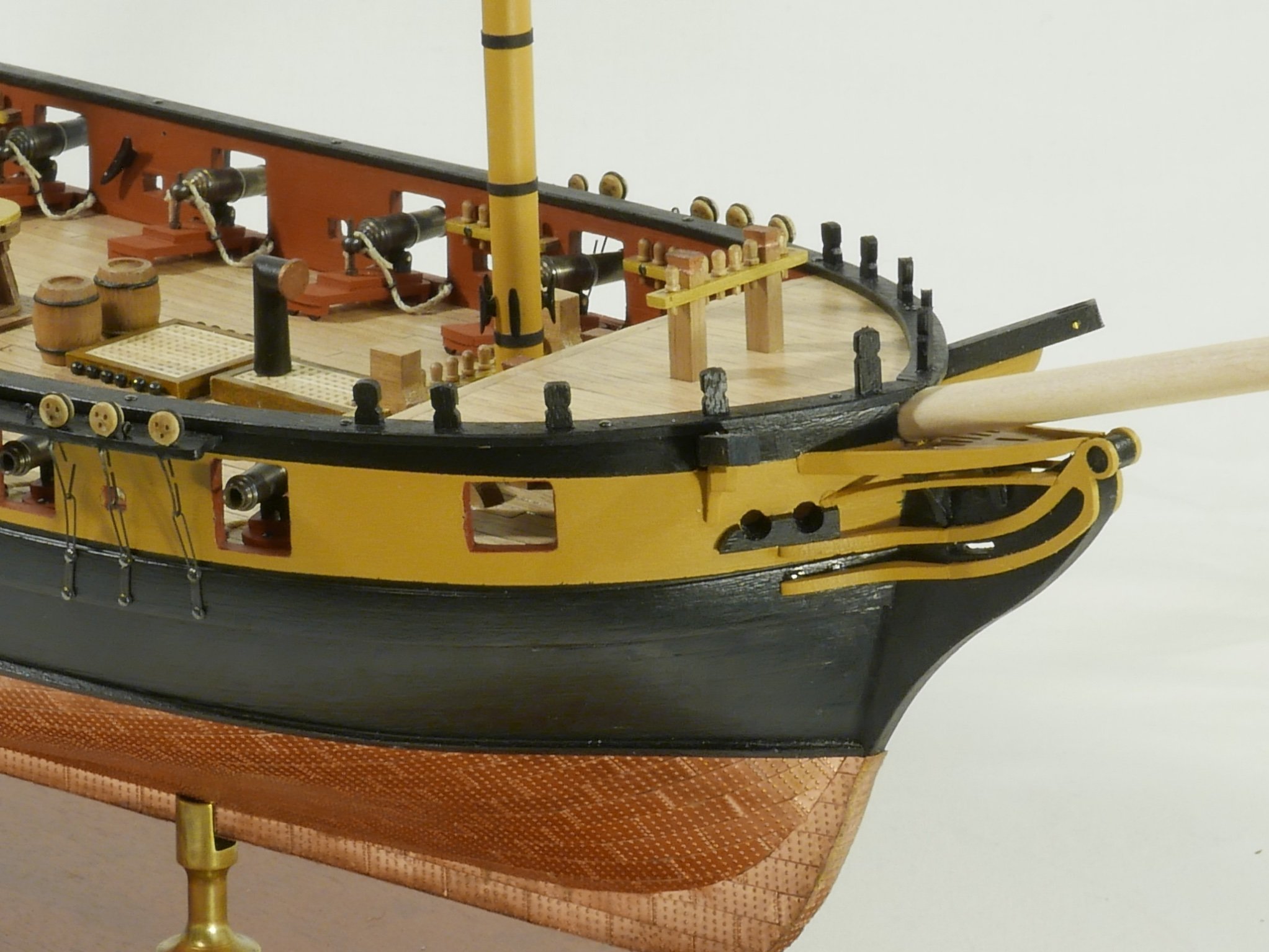
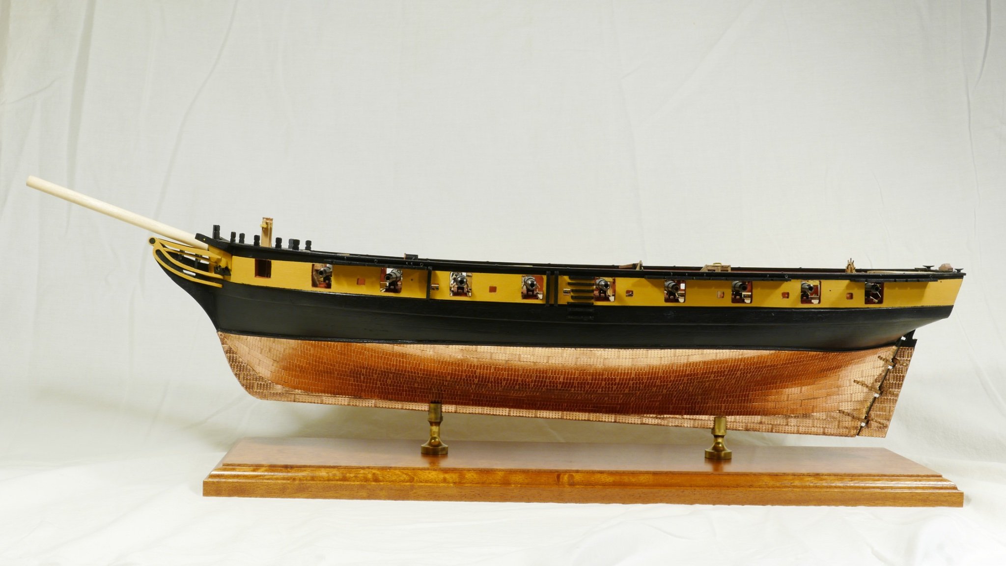
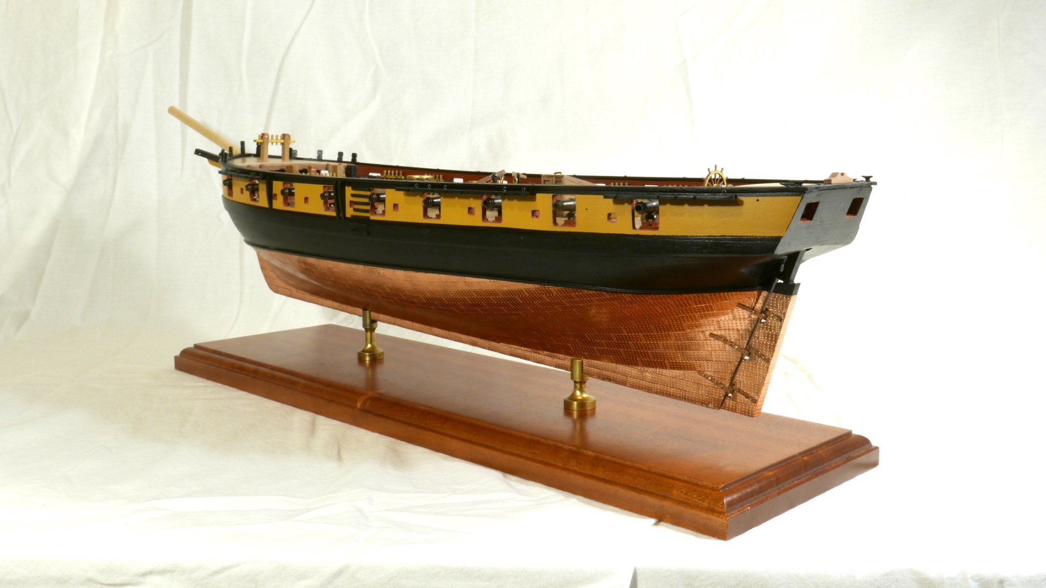
Well, the hull is pretty-well done. The chains and dead-eyes will wait until I have the masts marked up, so I get the lines for the shrouds right, and the boomkins look a bit delicate, so they will wait as well. All was fairly straightforward, just required time and patience. The supplied gunwale rail for the stern had a noticeable curve, which I did not manage to crate wen planking so I machined my own using my new Proxxon toy. To celebrate this milestone I got the proper camera out and rigged some lights. Here are a few pics for posterity (with a dummy bowsprit).


- GrandpaPhil, BenD, Dfell and 2 others
-
5
-
I meant to add, I'm happy for you that your health allows you to work up to retirement. My retirement is now 5 weeks away, and I see some ship building on the horizon...
-
Hi,
Masts! I'm getting close to completing the hull, so should be with you fairly soon.
I bought the DB 250 lathe, and the MF70 milling machine. Made a few sample pieces and they went well. I bought the dividing plate for the mill which makes machining hexagonal and square sections very precise and enjoyable. Will be machining out the slots in the bulwark rail in the next day or two so that will be the mill's first real job.
Mike
-
-
3 hours ago, James H said:
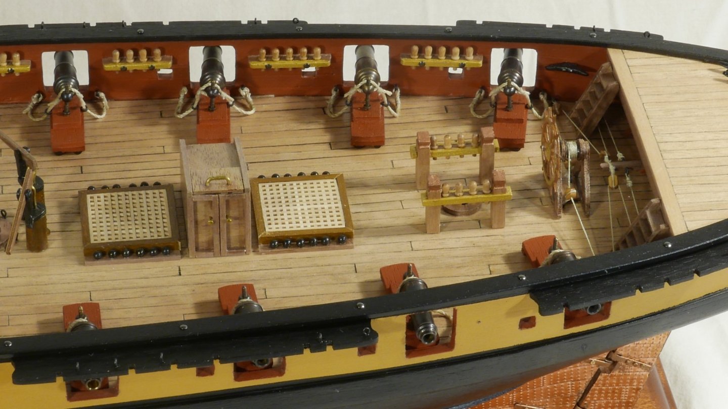
Remember those cannon port lids? Here they are, finally installed.
And very, very nice they look, too. Will you be documenting the rigging, as well James?
Having just spent a day at Portsmouth Historic Dockyard, can I say that this model would look entirely at home in the museum there. Exceptional work by Chris and James.
- Oboship, Old Collingwood, mtaylor and 2 others
-
5
-
-
Well Glenn, I think there is a point about a model design being time-efficient for the modeller. I can see no basis on which I could find enjoyment in cutting out gun ports through splintering stripwood that I had spent hours - days - getting just-so. Nor is there a lot of fun to be had in working out the extent to which the instructions has the assembly sequence wrong, or the drawings being nominal or indicative rather than instructive. And I don’t think that view differs much from what @ERS Rich was saying. It’s not so much about time saving as about be able to use time where it is most necessary. For all that, I still want to build a kit, not assemble it. And my word I want to build this one!
- mtaylor, ERS Rich, chris watton and 1 other
-
4
-
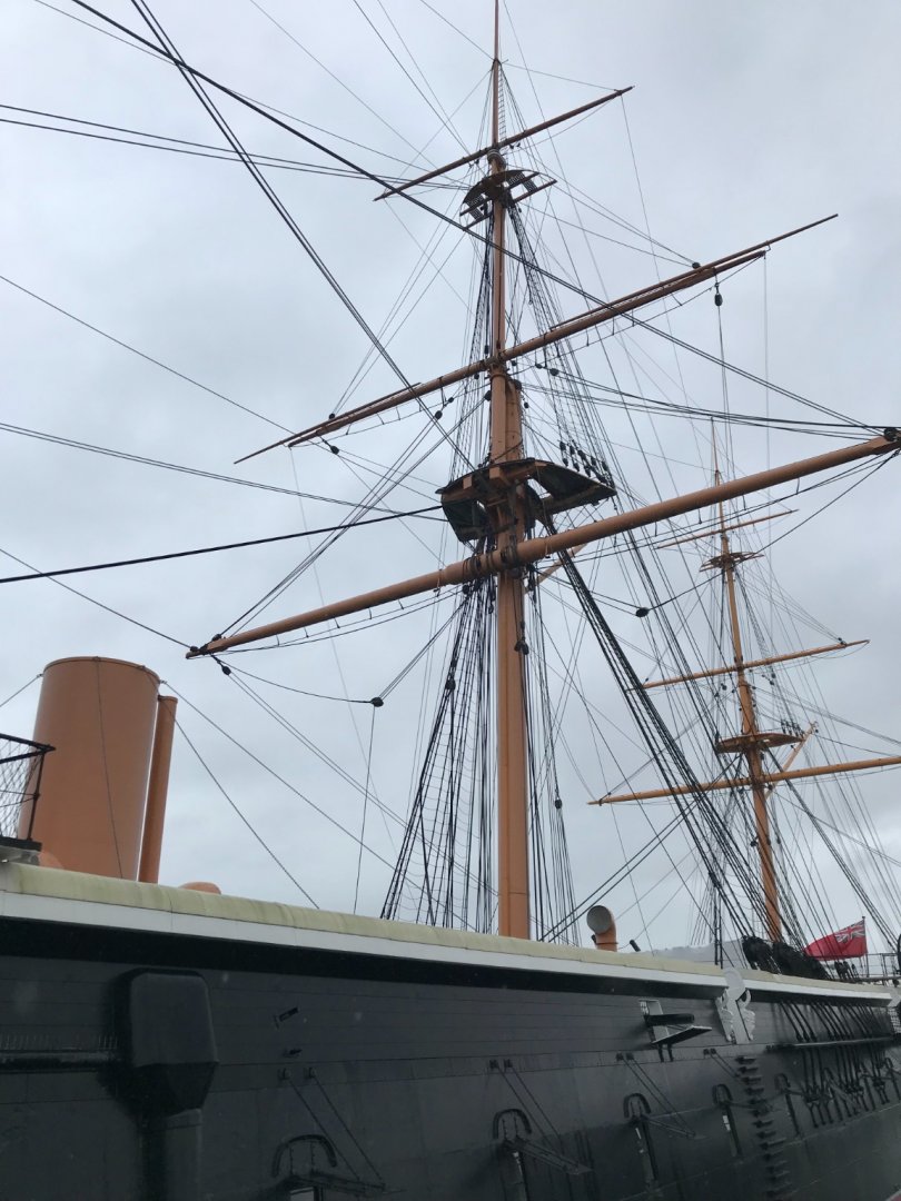
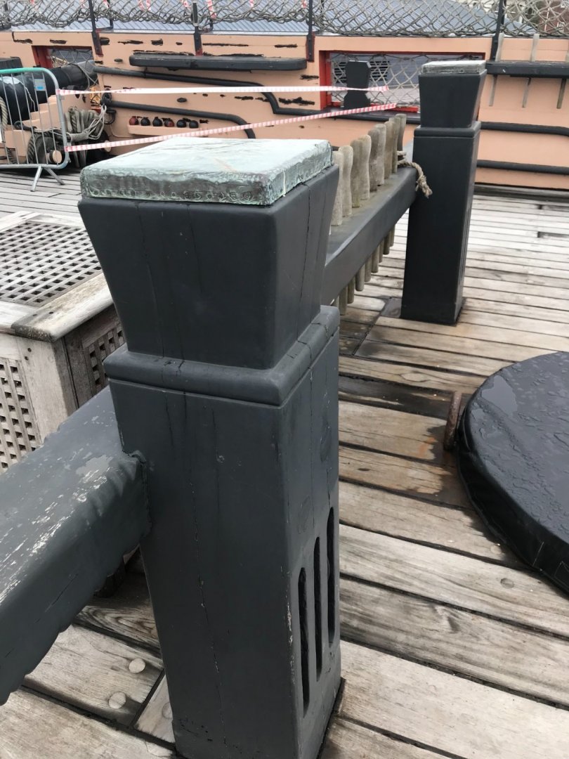
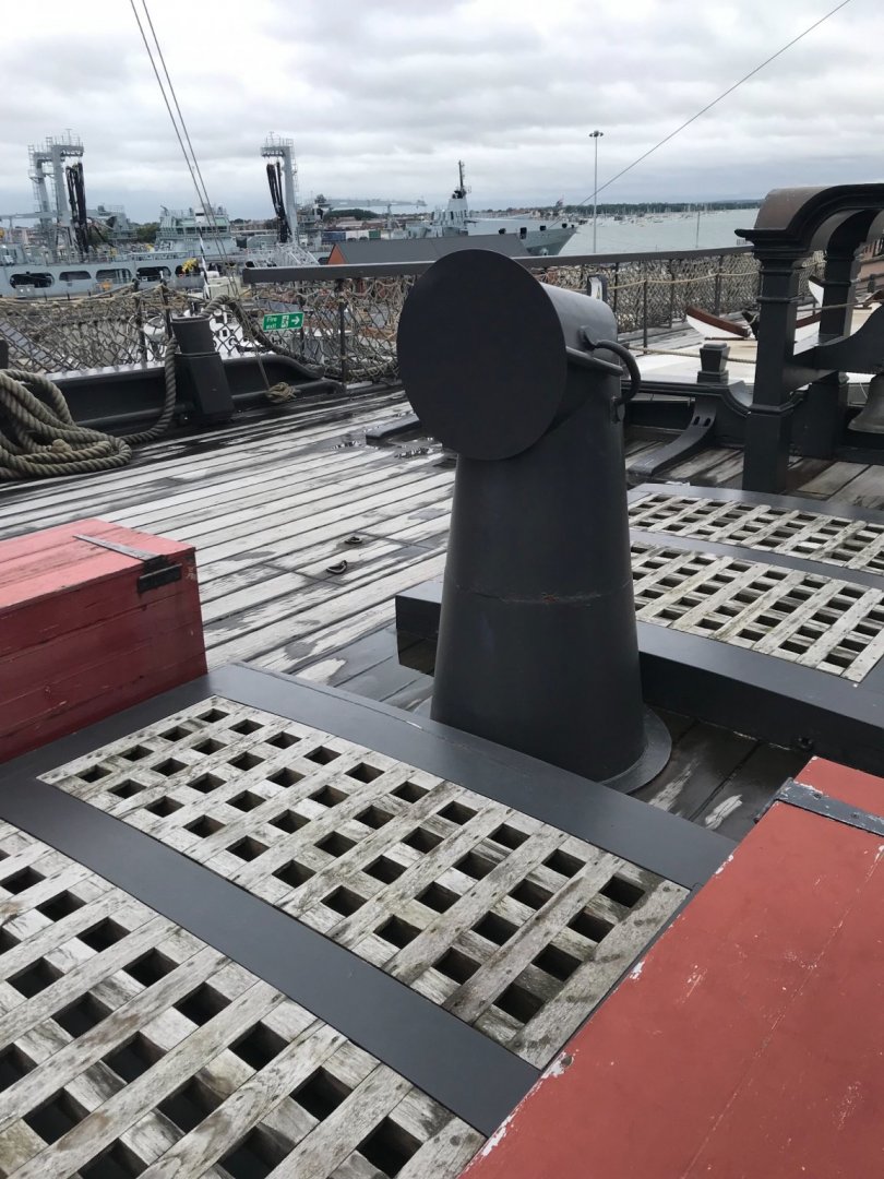
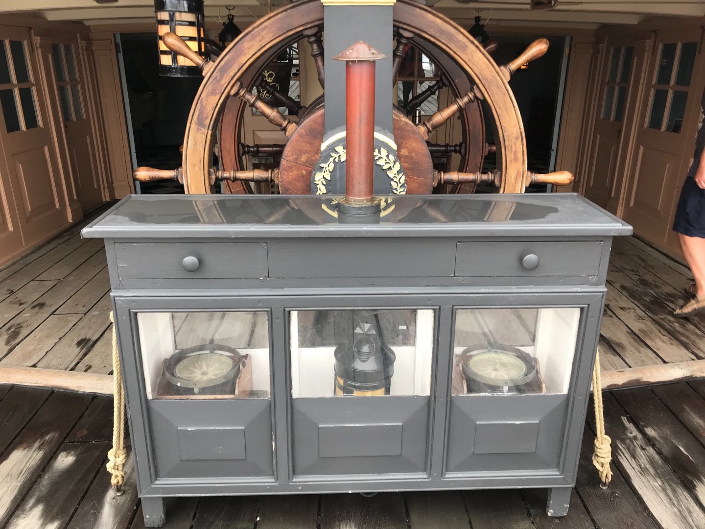
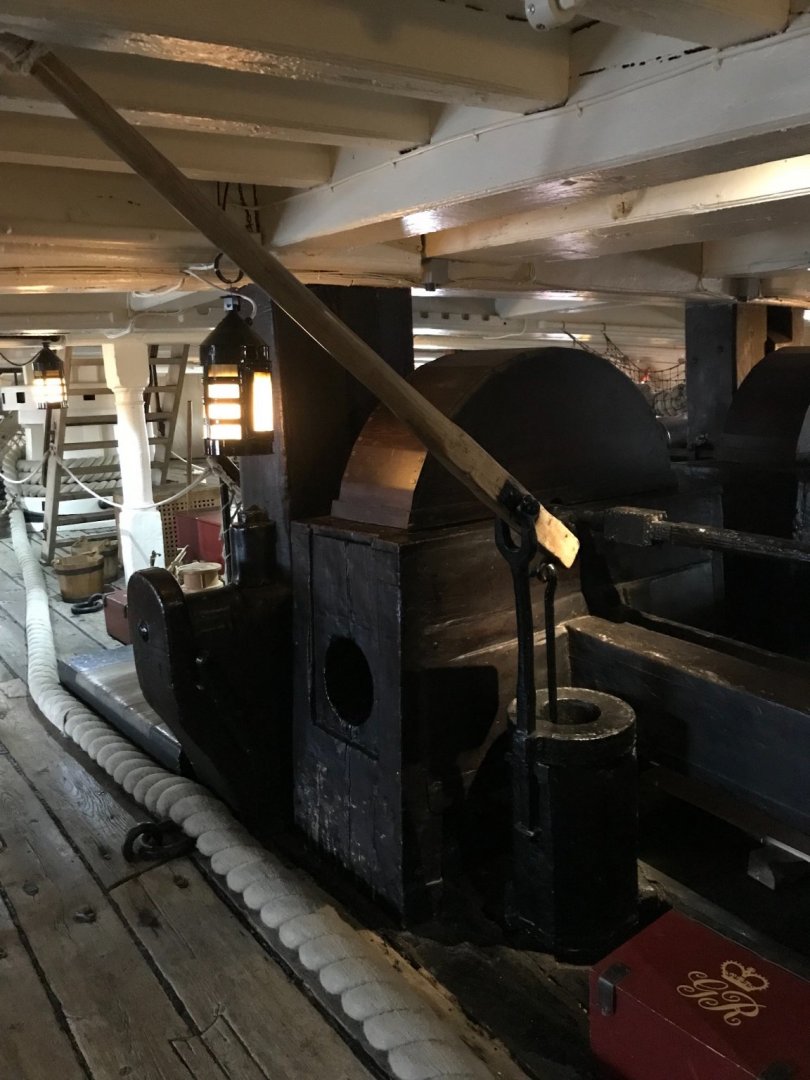
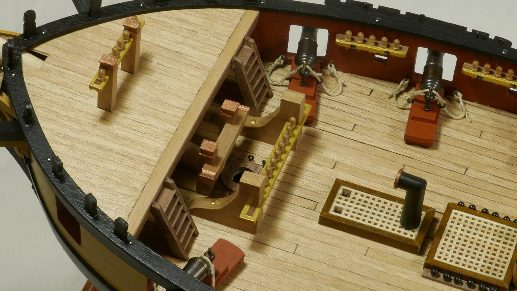
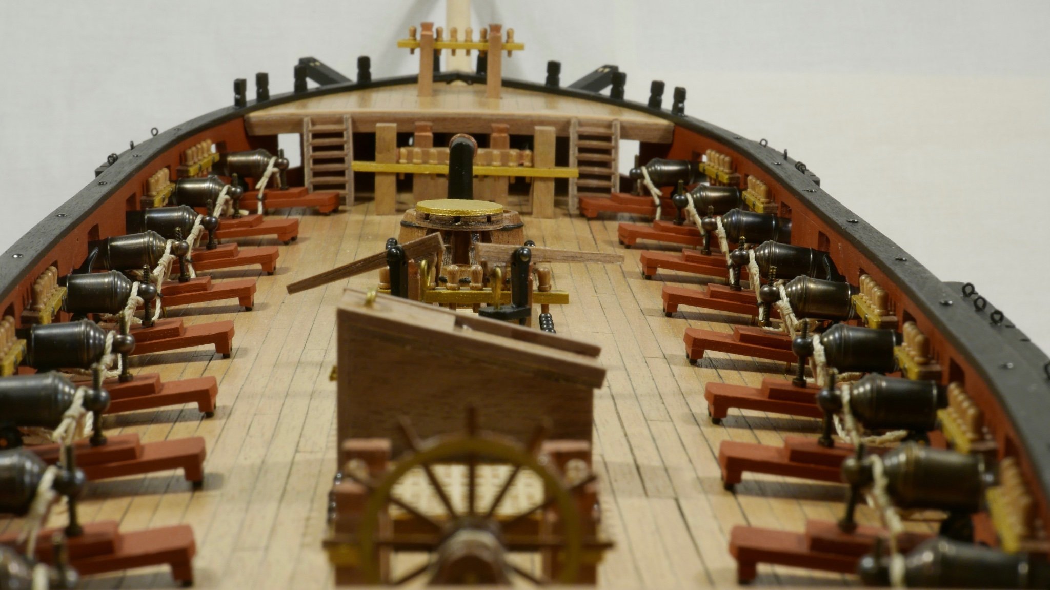
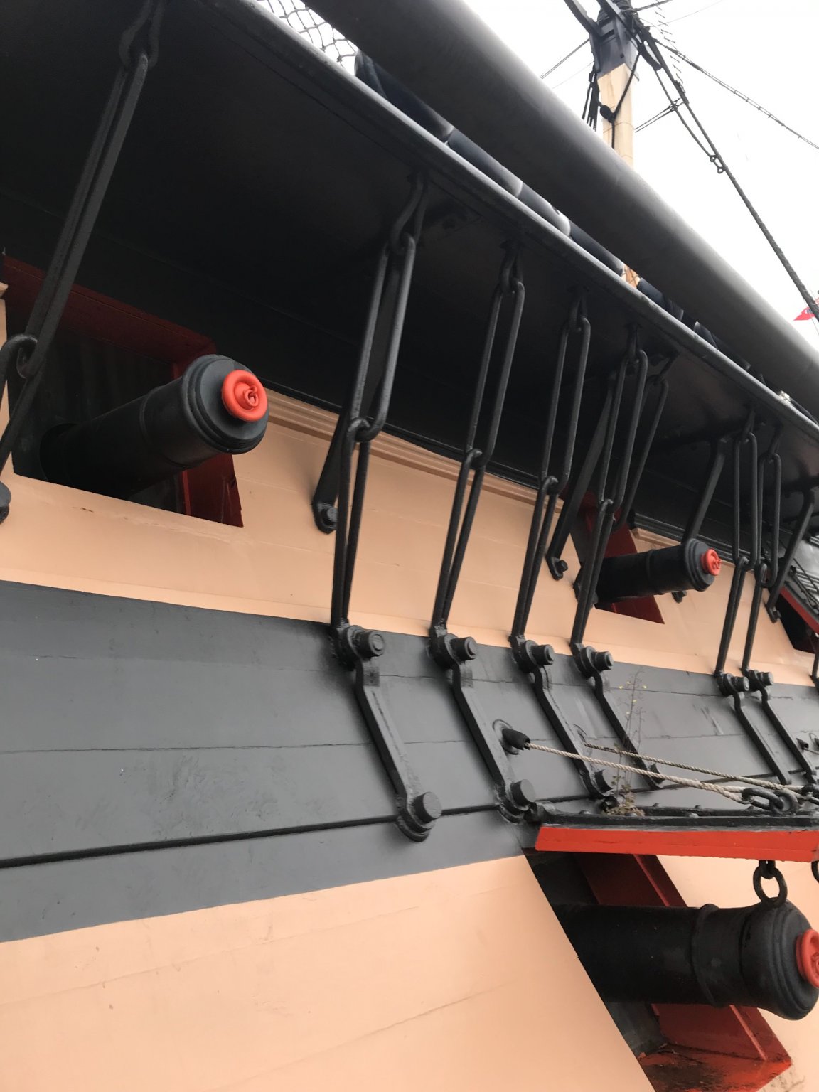
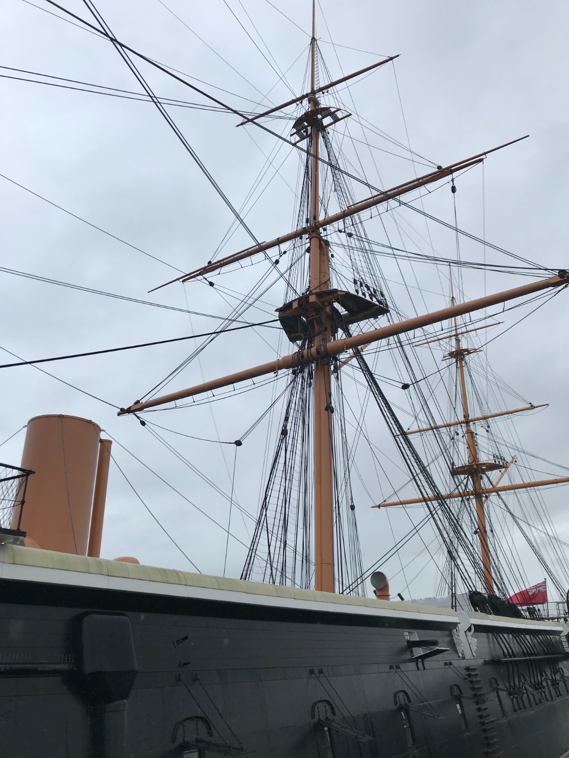
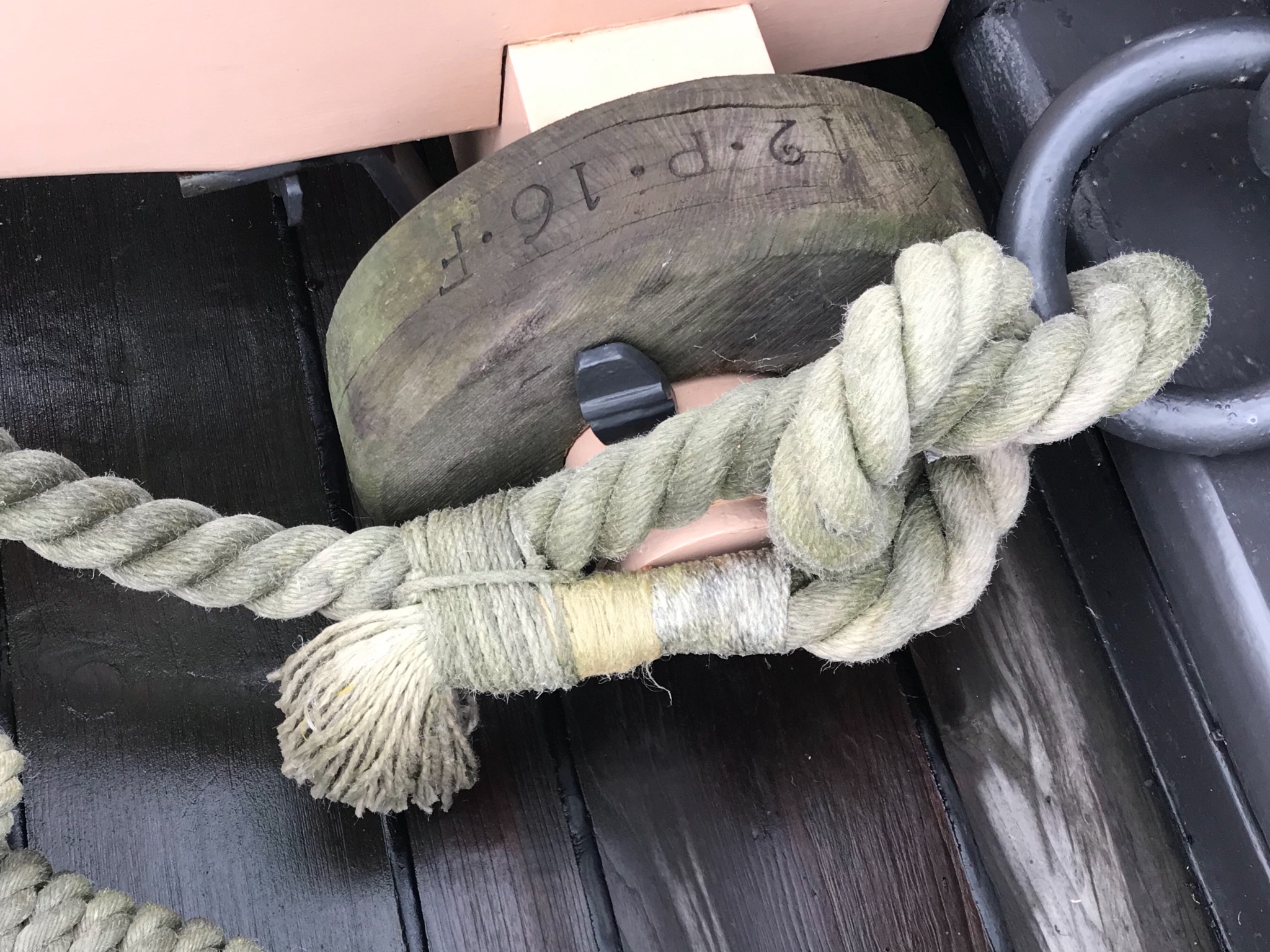
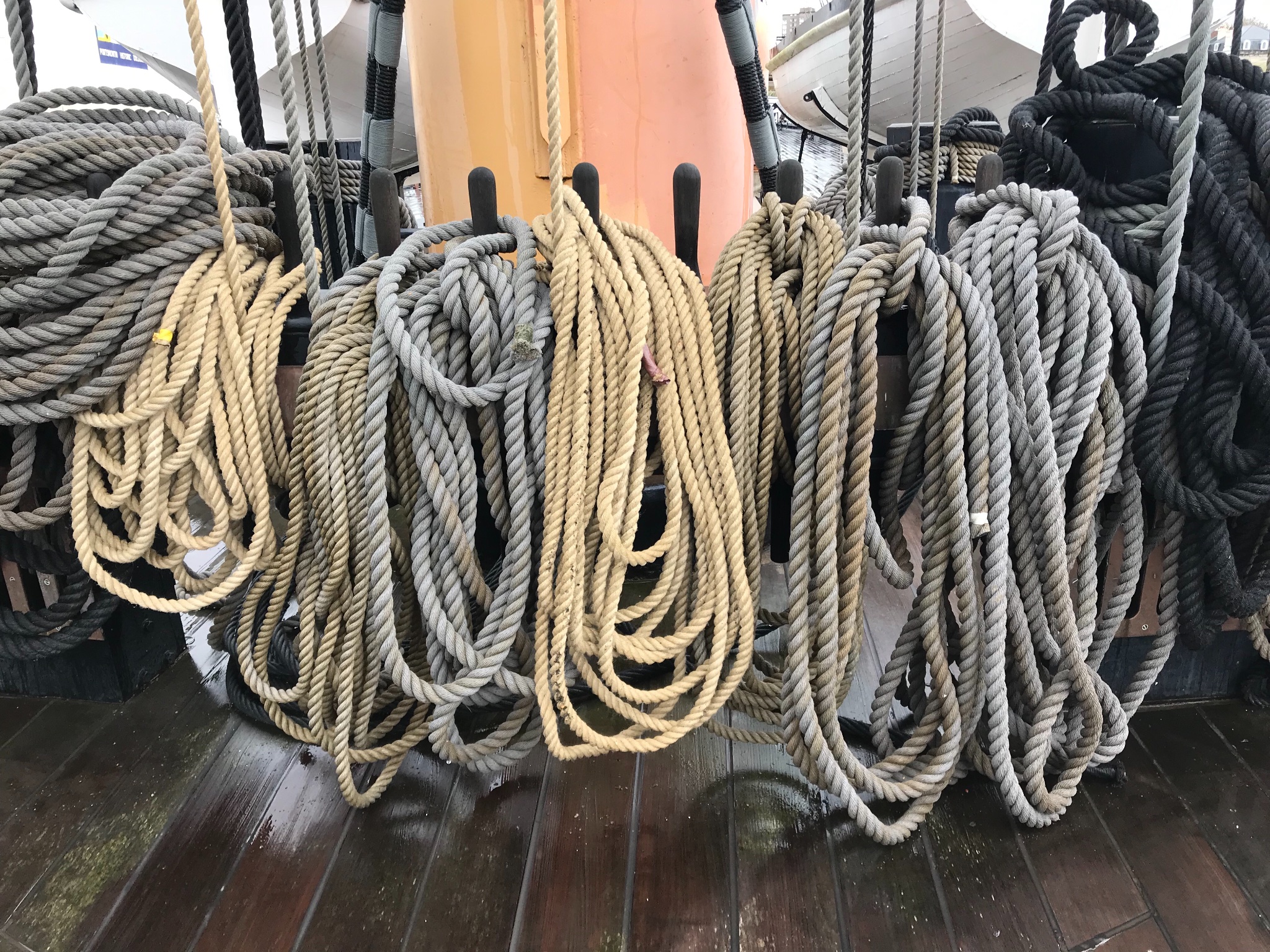
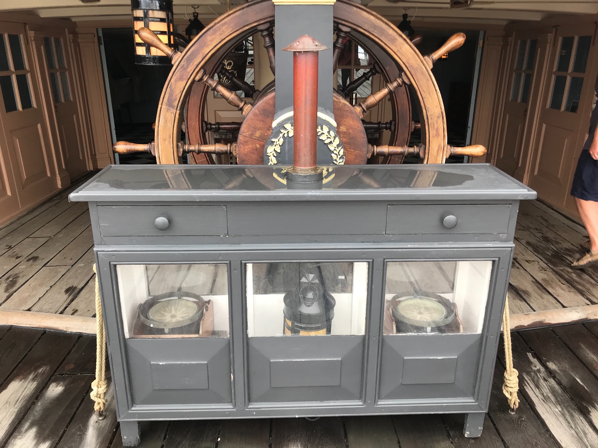
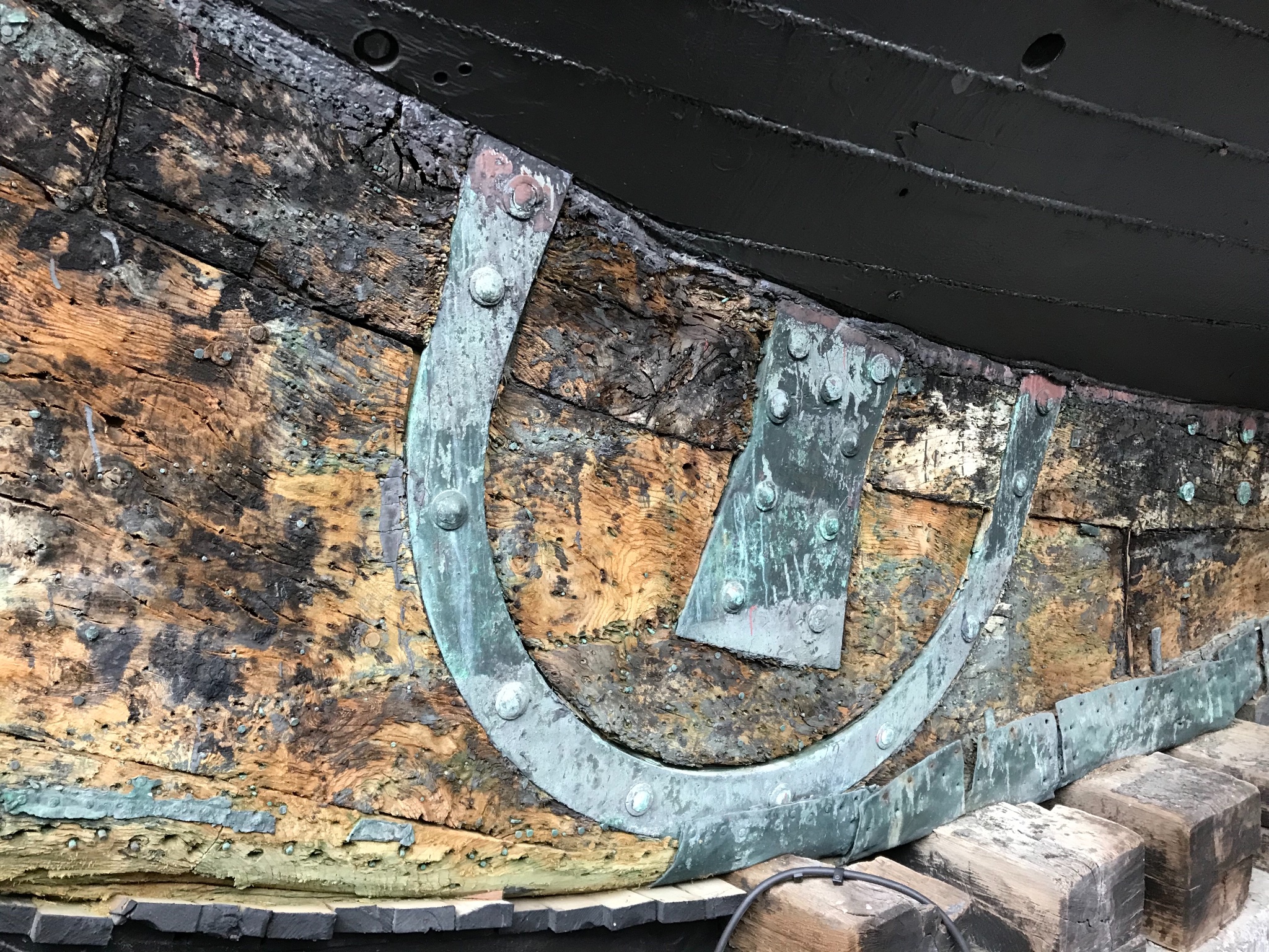
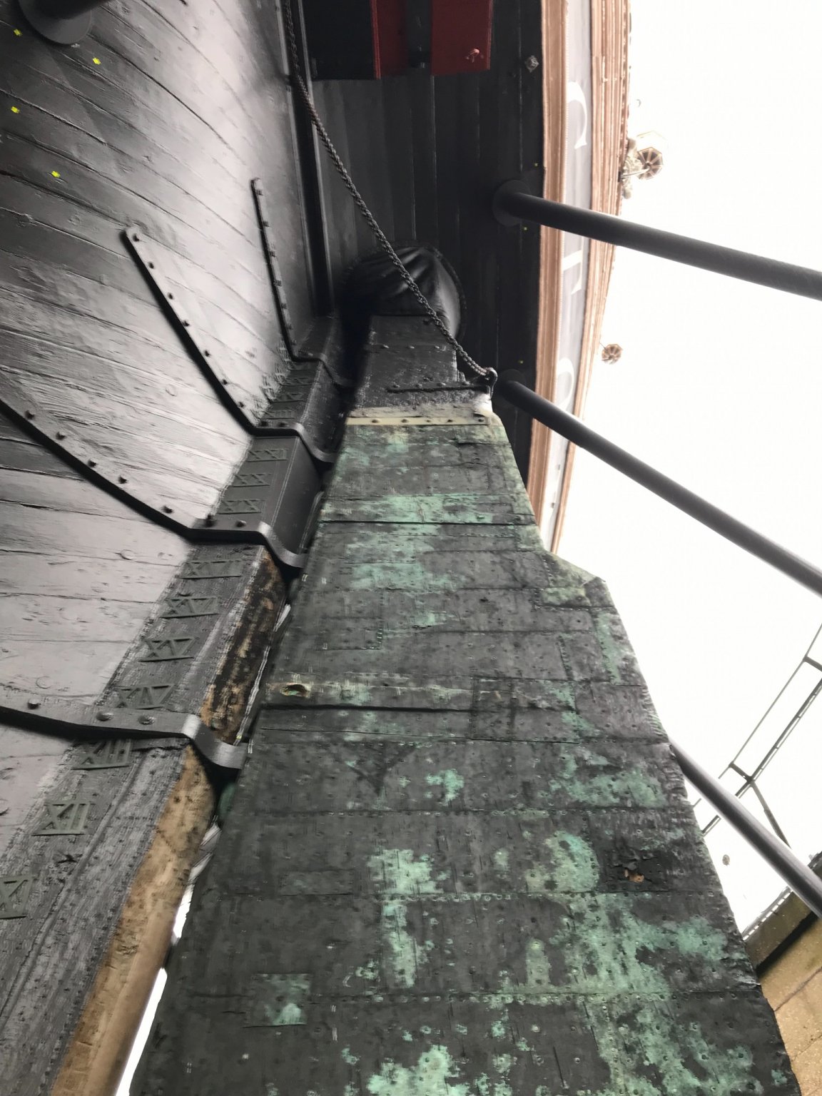
Just spent a very happy day at Portsmouth Historic Dockyard - torrential rain, but that just meant staying below deck, and in clear spells going “upstairs” or into the museum. Spent my time looking at details with a view to informing modelling. Some of relevance to Snake, others for the future. These are from Warrior and Victory, with one from the museum.
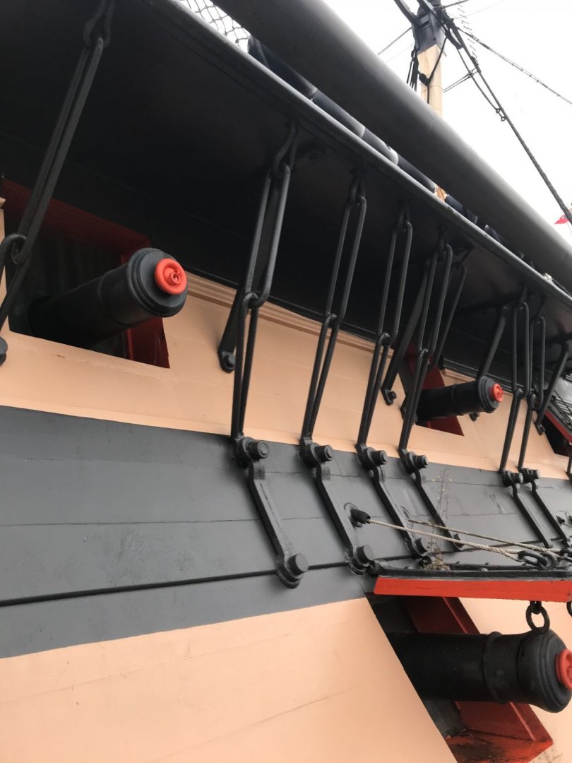
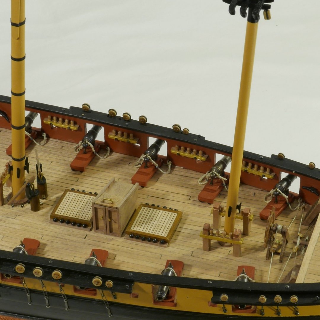
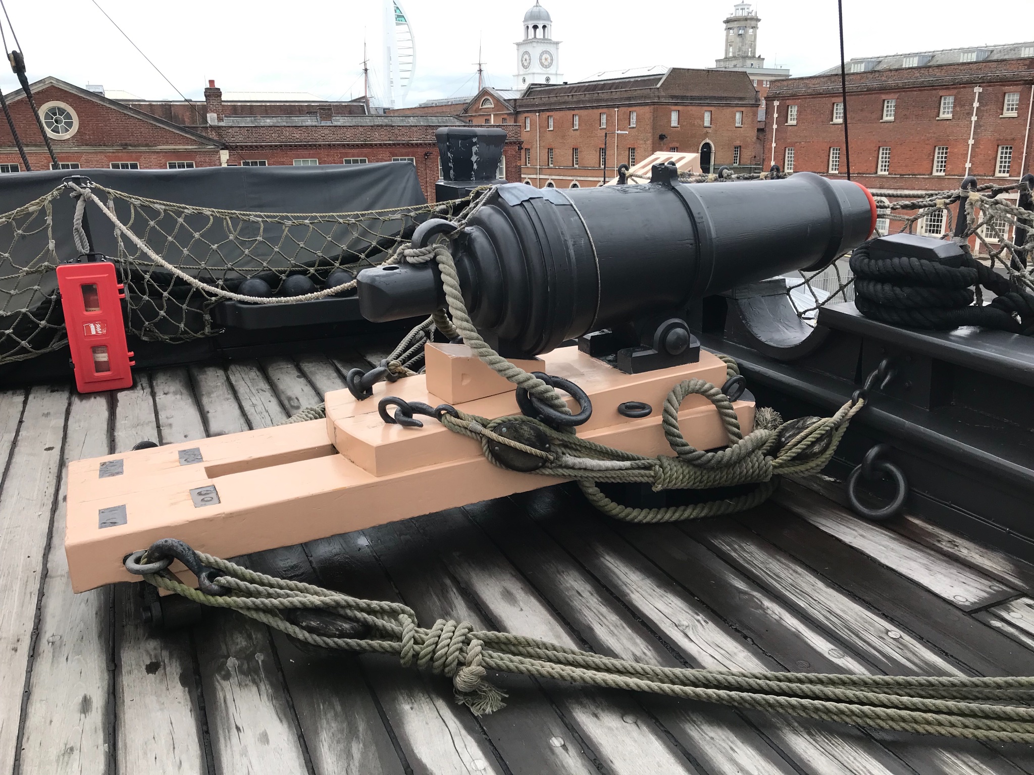
When I rigged the breechings, I followed the books on how to secure them to ring bolts. Didn’t really believe that a single knot with a little seizing would be strong enough, but seems that is what is used:
Here’s some more carronade rigging - though the breechings seem a little loose

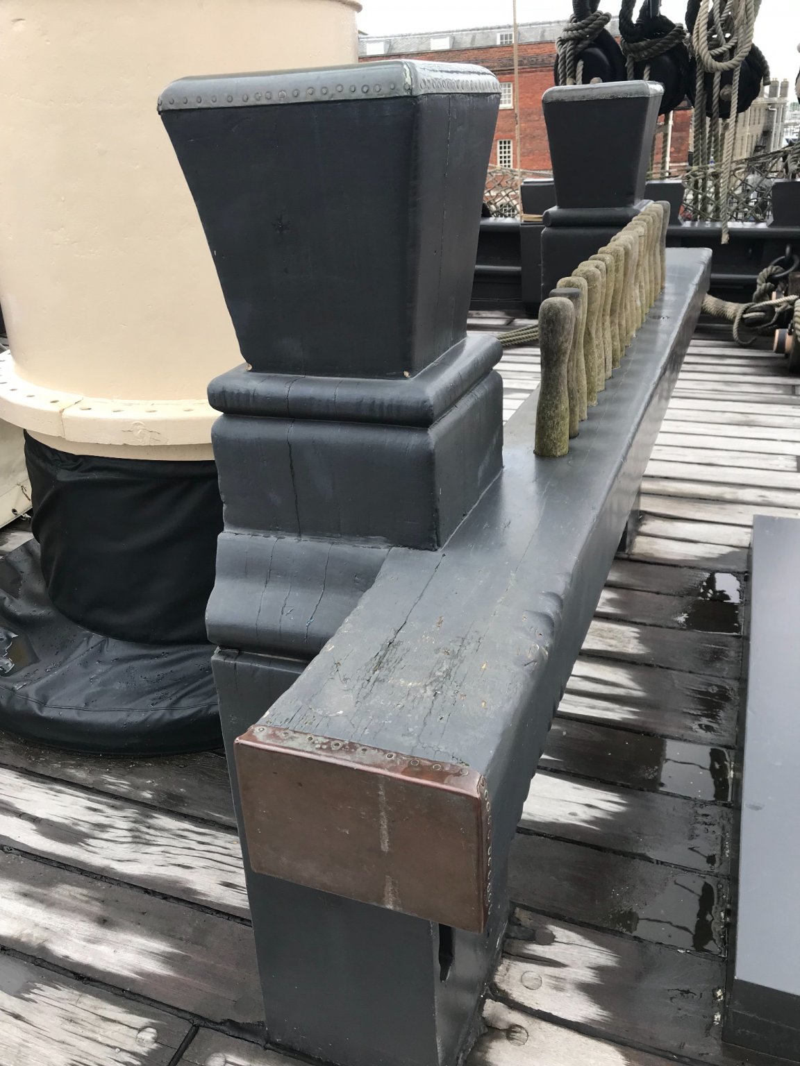
Petrejus says that the bits had copper caps and ends…


I rigged a galley flue just like this:
I want a binnacle, just like this, but can’t fit it in
But I can have an elm tree pump like this
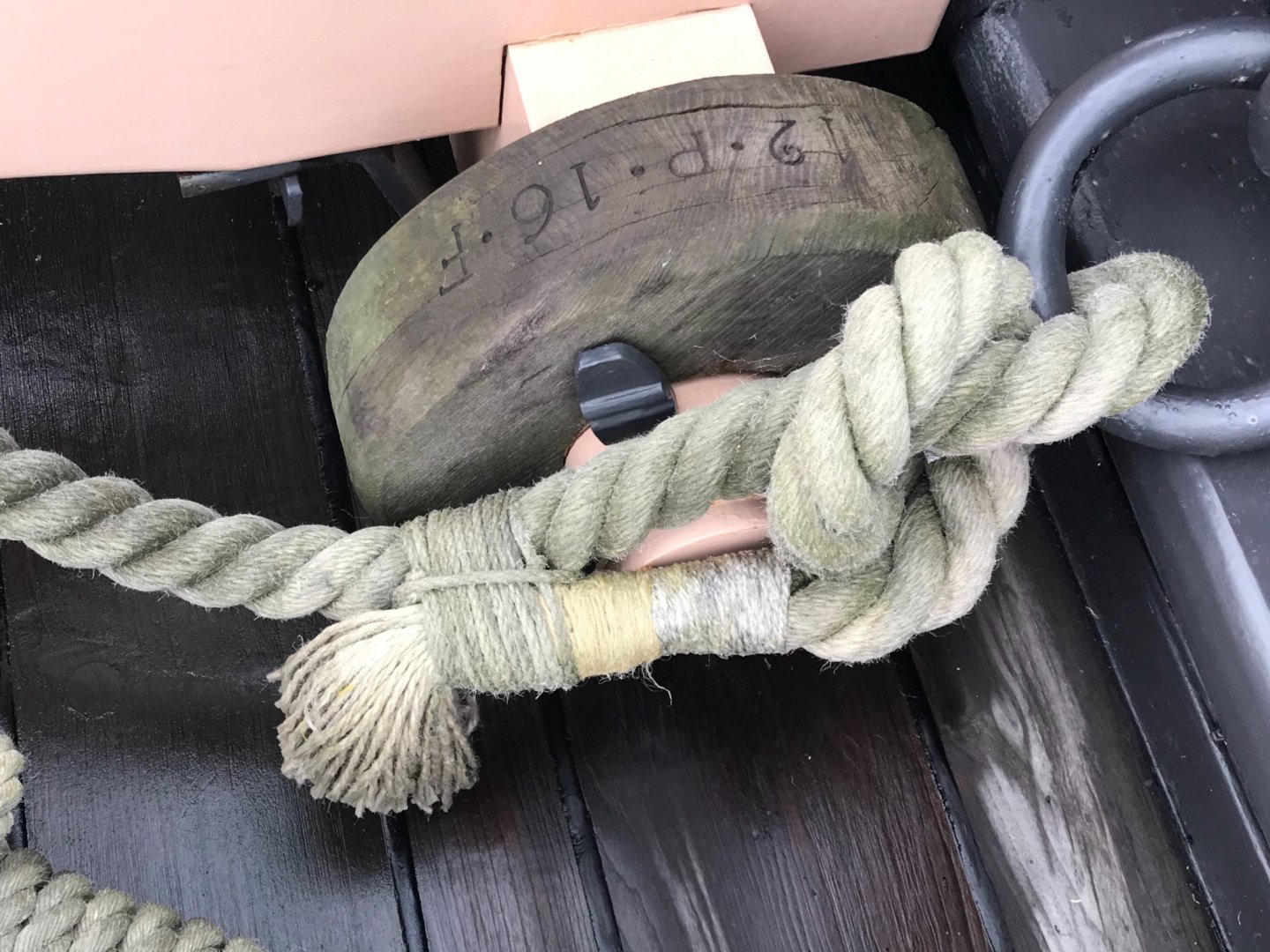
The new ( to me, anyway) access to the dry dock means you can see things up close. I had wondered what the horseshoe is for, now I know:

But gudgeons and pintles - entirely familiar

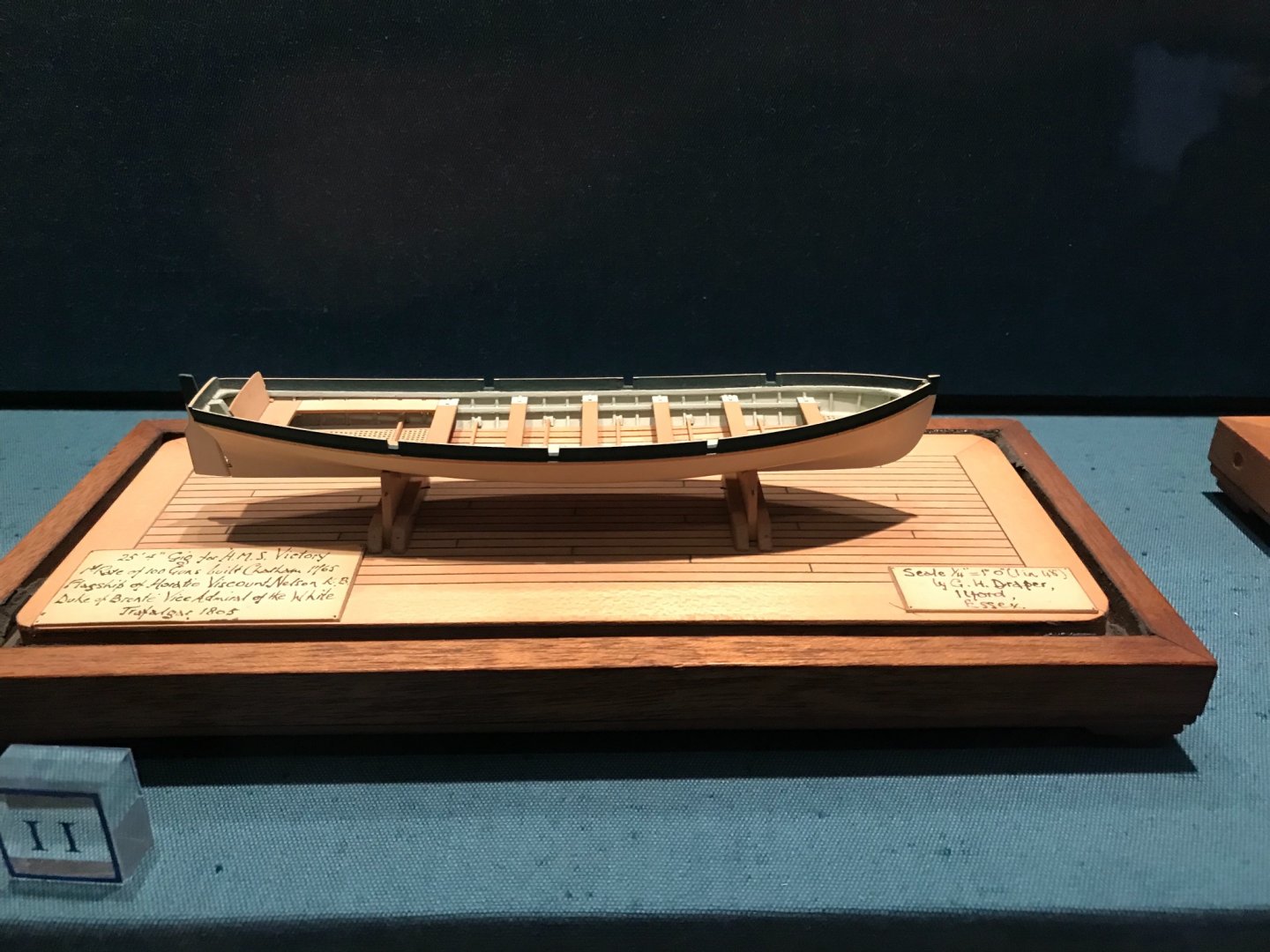
Have occasionala thought of rigging some boats for Snake. Beautiful set of models in the museum. Here’s one
- Beef Wellington, CiscoH, AJohnson and 2 others
-
5
-
-
-
-
22 hours ago, chris watton said:
Jim hasn't added the three gun port lids per side (last three gun ports have them) yet, but they are included (pre cut, of course)
Aha - and he has shown a photograph with an entirely sensible explanation. But why did/does she have only 3 (more) per side?
Mike
- KentM and Old Collingwood
-
2


HMS Snake by Mike_H - FINISHED - Caldercraft - 1:64
in - Kit build logs for subjects built from 1751 - 1800
Posted · Edited by Mike_H
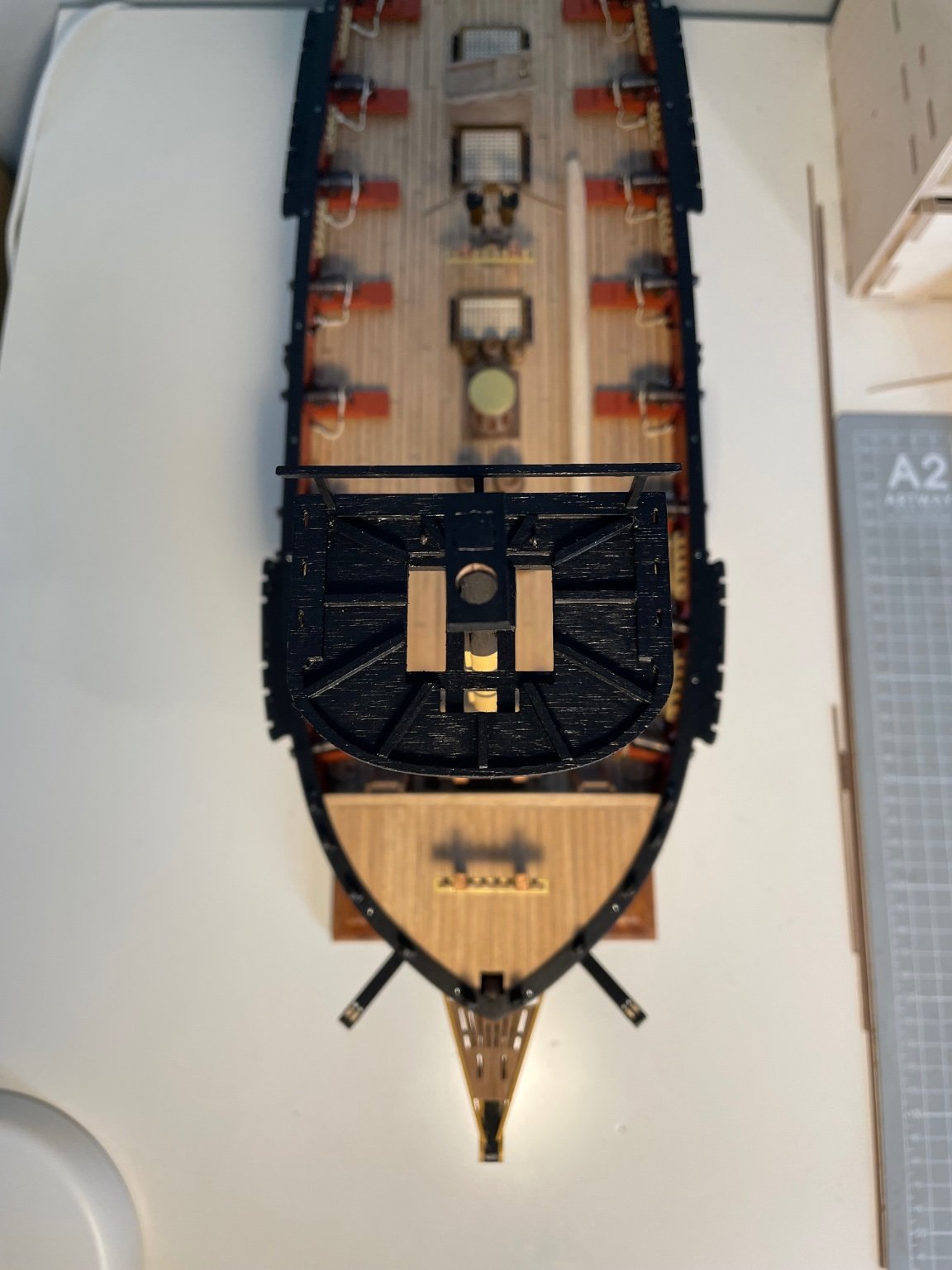
Bowsprit and Jib Boom
The bowsprit was remarkably fiddly, but gave lots of learning so I'm reasonably pleased.
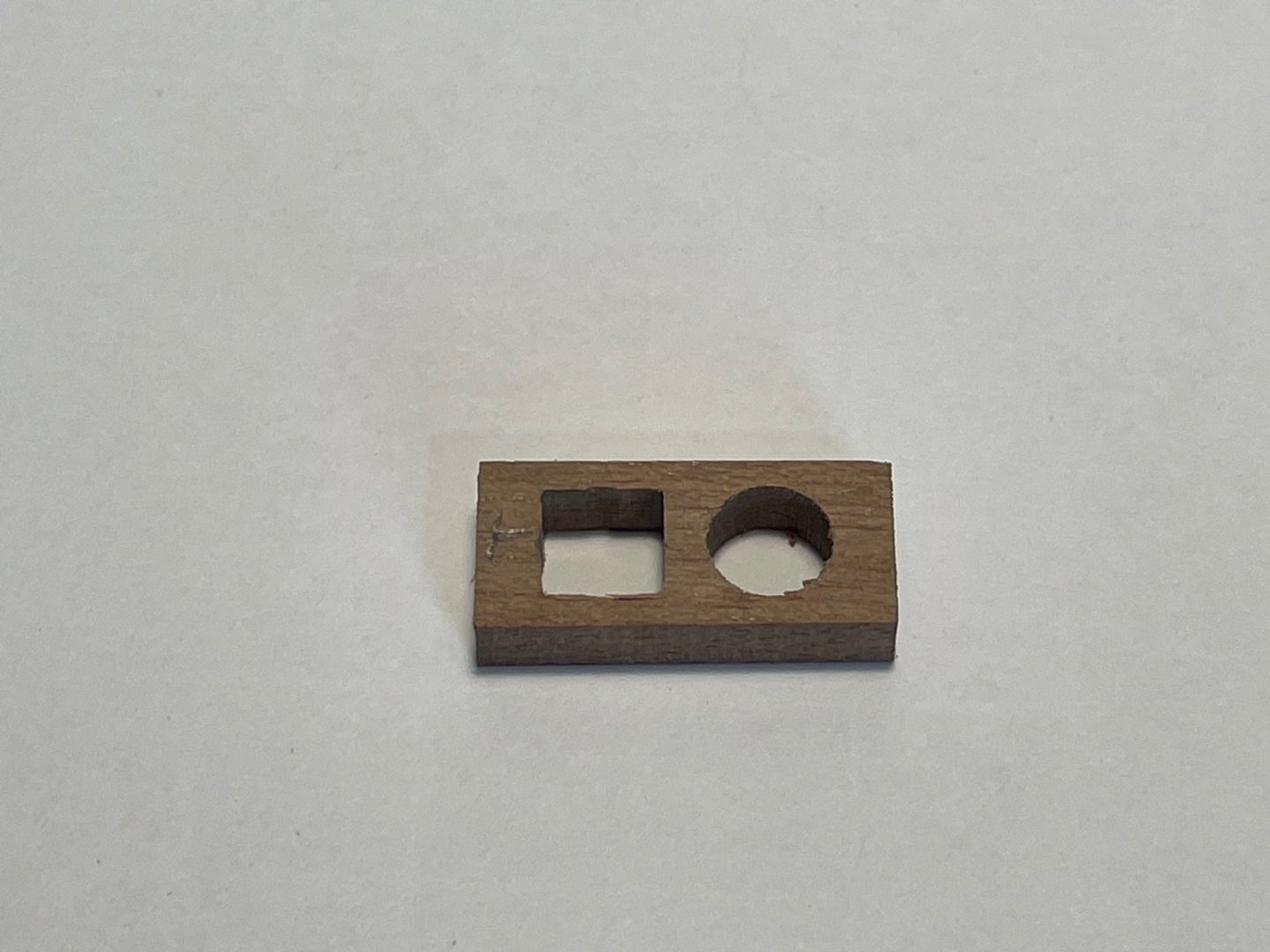
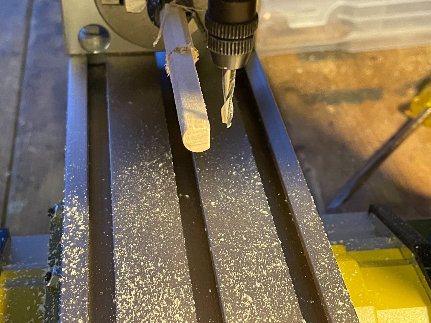
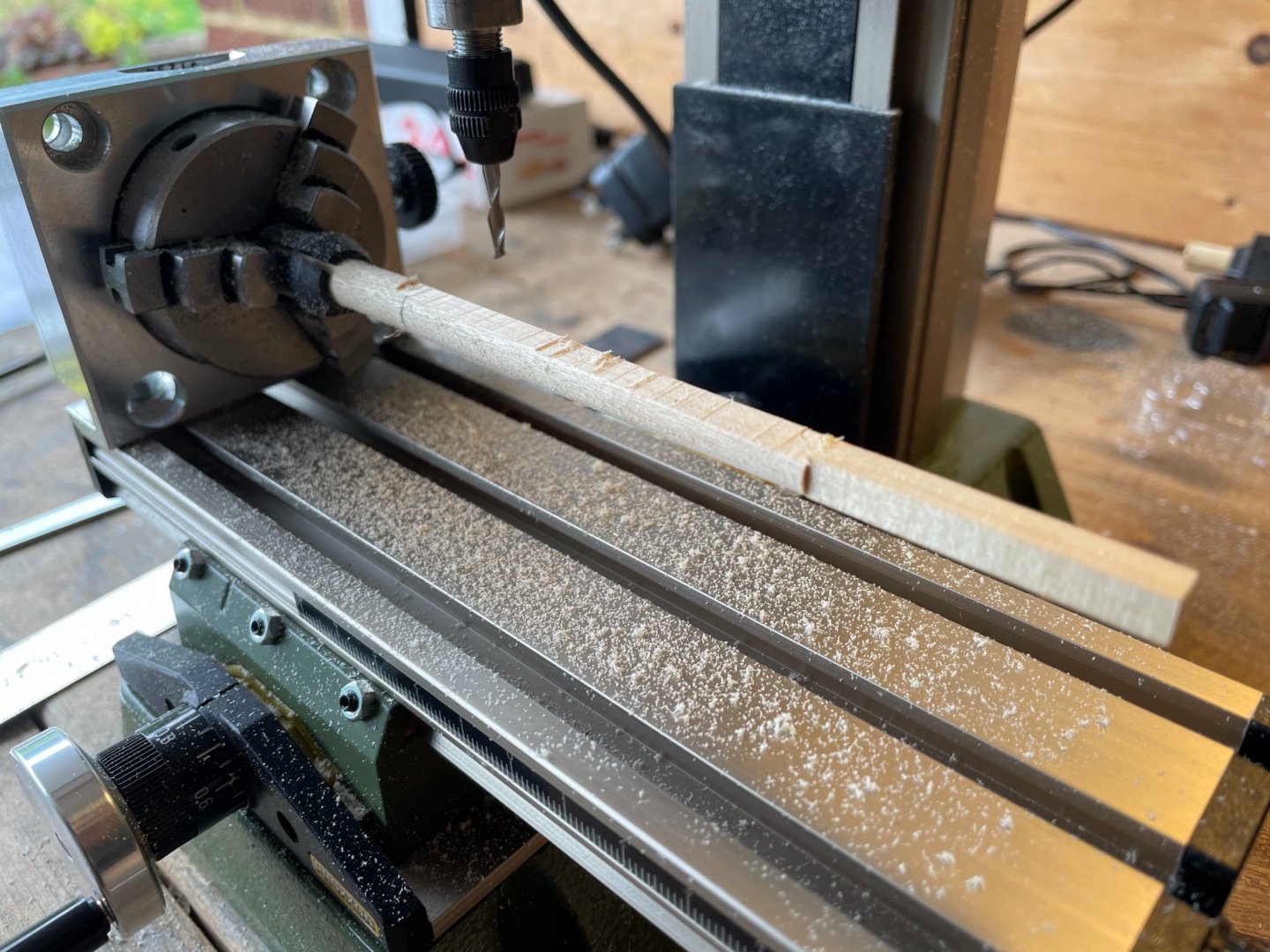
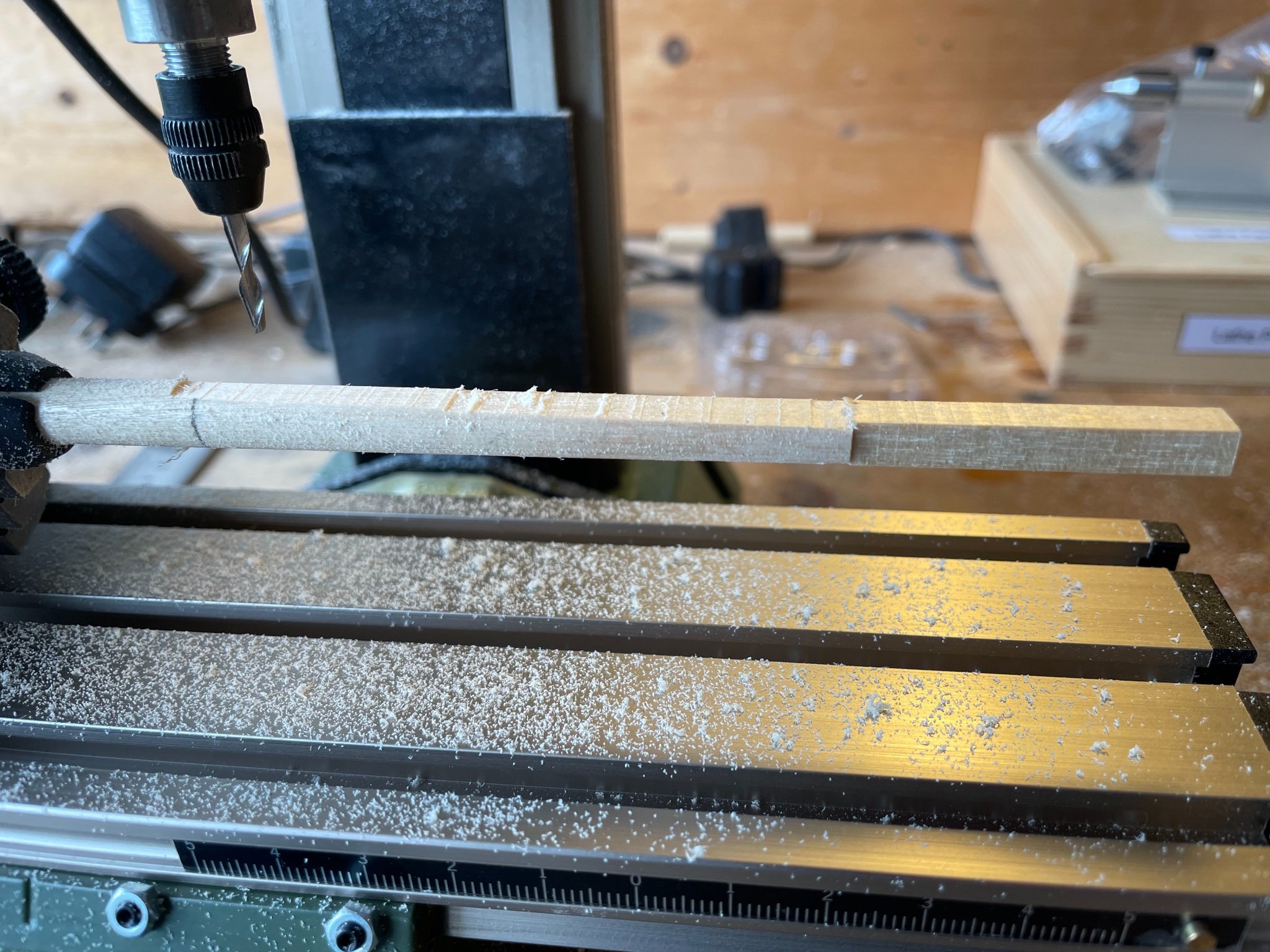
The bowsprit requires 13 cleats and a bee to be placed reasonably carefully. This I did by machining shallow slots using my Proxxon mill. I took the photos below after I had fitted the cleats, but the slot for the bee is visible. The square tenon to take the cap can also be seen. Machining that was relatively straightforward though the undercut on the top surface was a tittle tricky
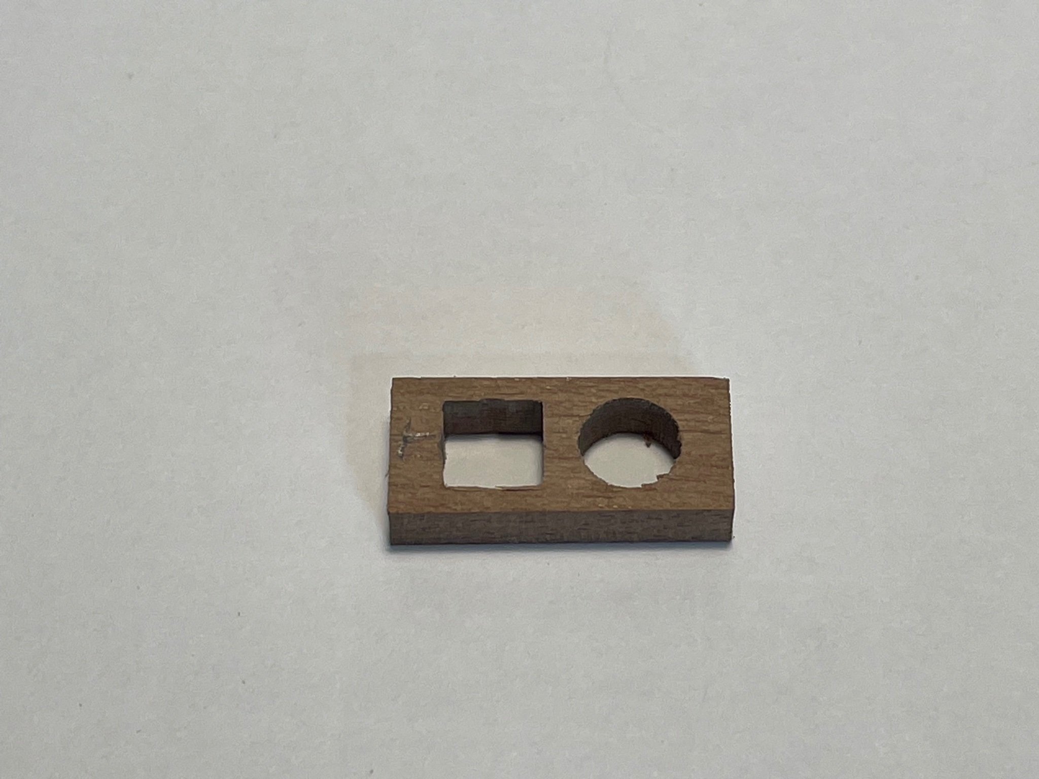
Far more tricky was the cap itself. As has been remarked before, the kit-provided part with two circular holes bored perpendicular to the surface is virtually useless. In the picture below, on the LHS you can see what happens when you machine a square slot for the tenon - it is not possible to fit the square slot around the circular hole (I did the geometry - but I'll spare you that). On the RHS is the cap I scratch built. Easy to machine, hard to design, so here's my sketch of the cross-section - crucial to that was determining the angle of the bowsprit (19º above horizontal), and the width of the jib boom seating bracket (2 mm).
Here it is assembled (with interim gammoning around the boom)
Bumkins added
Painted and rigged - with Petrejus's "hour glass" gammoning.